

Page 1
Unified Office Gateway
UMG-2000 / UMG-2200
User's Manual
Page 2

Copyright
Copyright (C) 2010 PLANET Technology Corp. All rights reserved.
The products and programs described in this User’s Manual are licensed products of PLANET
Technology, This User’s Manual contains proprietary information protected by copyright, and this
User’s Manual and all accompanying hardware, software, and documentation are copyrighted.
No part of this User’s Manual may be copied, photocopied, reproduced, translated, or reduced to
any electronic medium or machine-readable form by any means by electronic or mechanical.
Including photocopying, recording, or information storage and retrieval systems, for any purpose
other than the purchaser's personal use, and without the prior express written permission of
PLANET Technology.
Disclaimer
PLANET Technology does not warrant that the hardware will work properly in all environments and
applications, and makes no warranty and representation, either implied or expressed, with respect
to the quality, performance, merchantability, or fitness for a particular purpose.
PLANET has made every effort to ensure that this User’s Manual is accurate; PLANET disclaims
liability for any inaccuracies or omissions that may have occurred.
Information in this User’s Manual is subject to change without notice and does not represent a
commitment on the part of PLANET. PLANET assumes no responsibility for any inaccuracies that
may be contained in this User’s Manual. PLANET makes no commitment to update or keep current
the information in this User’s Manual, and reserves the right to make improvements to this User’s
Manual and/or to the products described in this User’s Manual, at any time without notice.
If you find information in this manual that is incorrect, misleading, or incomplete, we would
appreciate your comments and suggestions.
FCC Warning
This equipment has been tested and found to comply with the limits for a Class A digital device,
pursuant to Part 15 of the FCC Rules. These limits are designed to provide reasonable protection
against harmful interference when the equipment is operated in a commercial environment. This
equipment generates, uses, and can radiate radio frequency energy and, if not installed and used in
accordance with the Instruction manual, may cause harmful interference to radio communications.
Operation of this equipment in a residential area is likely to cause harmful interference in which
case the user will be required to correct the interference at his own expense.
FCC Caution
To assure continued compliance (example-use only shielded interface cables when connecting to
computer or peripheral devices). Any changes or modifications not expressly approved by the party
responsible for compliance could void the user’s authority to operate the equipment.
This device complies with Part 15 of the FCC Rules. Operation is subject to the Following two
conditions: (1) This device may not cause harmful interference, and (2) this Device must accept any
interference received, including interference that may cause undesired operation.
CE mark Warning
The is a class A device, In a domestic environment, this product may cause radio interference, in
which case the user may be required to take adequate measures.
Energy Saving Note of the Device
This power required device does not support Stand by mode operation.
For energy saving, please remove the DC-plug or push the hardware Power Switch to OFF position
to disconnect the device from the power circuit.
Without remove the DC-plug or switch off the device, the device will still consuming power from the
power circuit. In the view of Saving the Energy and reduce the unnecessary power consuming, it is
strongly suggested to switch off or remove the DC-plug for the device if this device is not intended to
be active.
2
Page 3

Trademarks
The PLANET logo is a trademark of PLANET Technology. This documentation may refer to
numerous hardware and software products by their trade names. In most, if not all cases, these
designations are claimed as trademarks or registered trademarks by their respective companies.
WEEE Warning
To avoid the potential effects on the environment and human health as a result of
the presence of hazardous substances in electrical and electronic equipment, end
users of electrical and electronic equipment should understand the meaning of the
crossed-out wheeled bin symbol. Do not dispose of WEEE as unsorted municipal
waste and have to collect such WEEE separately.
Safety
This equipment is designed with the utmost care for the safety of those who install and use it.
However, special attention must be paid to the dangers of electric shock and static electricity when
working with electrical equipment. All guidelines of this and of the computer manufacture must
therefore be allowed at all times to ensure the safe use of the equipment.
Revision
User’s Manual for PLANET Unified Office Gateway
Model: UMG-2000 / UMG-2200
Rev: 1.0 (May. 2010)
Part No.: EM-UMG2000_2200_v1.0
3
Page 4

Table of Contents
1. Introduction................................................................................................................7
1.1 Product Features.................................................................................................8
1.2 Package Contents.............................................................................................10
1.3 Application.........................................................................................................11
1.4 Outlook ..............................................................................................................13
1.4.1 Front Panel ...............................................................................................13
1.4.2 Rear Panel ................................................................................................14
1.5 Technical Specifications...................................................................................15
2. Installation................................................................................................................17
2.1 Hardware Installaion .........................................................................................17
2.1.1 Unpack the UMG-2000 / UMG-2200.........................................................17
2.1.2 Choosing a Setup Location.......................................................................17
2.1.3 Preparing for Setup
2.1.4 Precautions
2.1.5 Installation Consideration..........................................................................18
2.1.6 The Desktop Brackets Installation.............................................................19
2.1.7 The Rack Mount Installation......................................................................19
2.1.8 The Hard Disk Inst
2.2 Physical Connection
2.2.1 WAN Connection.......................................................................................22
2.2.2 LAN Port Connection ................................................................................22
2.2.3 PSTN FXO Port Connection .....................................................................23
2.3 Quick Setup Wizard ..........................................................................................24
2.3.1 First Time Login ........................................................................................24
2.3.2 Welcom to Quick Start...............................................................................25
3. Web Management - Home .......................................................................................33
3.1 Overview ............................................................................................................33
3.2 Spanning Tree Protocol ....................................................................................35
3.3 Alert Log ............................................................................................................35
4. Web Management - User
4.1 User Overvie
4.2 Deleting a User Account...................................................................................37
4.3 Updating the User Setting
4.4 Creating a User Account
4.5 Departments and Group
4.6 Deleting a Group
5. Web Management - Network ...................................................................................41
5.1 Overview ............................................................................................................41
5.2 Internet...............................................................................................................43
5.3 Local Network....................................................................................................43
5.4 Service ...............................................................................................................44
5.5 The VPN Log......................................................................................................44
6. Web Management - Wireless...................................................................................45
6.1 Overview ............................................................................................................46
6.2 Wireless Setting
6.3 Wireless Client
6.4 Blocking the Connected Wireless Client ........................................................48
6.5 Wireless MAC Block List ..................................................................................49
7. Web Management - Storage....................................................................................50
7.1 Storage Overview
7.2 View a Volume by SMB .....................................................................................53
...............................................................................................18
w ...................................................................................................36
...............................................................................................40
................................................................................................47
s ................................................................................................48
..............................................................................................52
...................................................................................18
allation .........................................................................21
.........................................................................................22
.........................................................................................36
................................................................................37
..................................................................................38
s .................................................................................39
4
Page 5

7.3 Updating a Volume ............................................................................................53
7.4 Deleting a Volume .............................................................................................54
7.5 Creating a Storage Volume...............................................................................55
7.6 Storage Setting..................................................................................................57
7.7 Storage Bakcup and Restore ...........................................................................58
7.8 The Storage Log................................................................................................60
8. Web Management - PBX..........................................................................................61
8.1 IP PBX Overview ...............................................................................................62
8.2 IP PBX Feature Setting .....................................................................................63
8.3 IP PBX Conference............................................................................................64
8.4 IP PBX Call Rules..............................................................................................65
8.5 IP PBX Channel Setting ....................................................................................66
8.6 IP PBX Call Reference ......................................................................................67
8.7 IP PBX Call Log
9. Web Management - Email
.................................................................................................69
........................................................................................70
9.1 Email Overview..................................................................................................71
9.2 Email Basic Setting...........................................................................................72
9.3 Email Blacklist...................................................................................................74
9.4 Email Alias
9.5 Email For
.........................................................................................................75
ward ...................................................................................................76
9.6 Email Log...........................................................................................................77
10. Web Management - FTP ........................................................................................78
10.1 FTP Overview ..................................................................................................78
10.2 FTP Setting ......................................................................................................78
10.3 FTP Account ....................................................................................................79
10.4 FTP Log............................................................................................................80
11. Web Management - Security .................................................................................81
11.1 Security Overview ...........................................................................................82
11.2 Security Setting...............................................................................................84
11.3 Content Filter ...................................................................................................85
11.4 Access Control ................................................................................................86
11.5 Port Forwarding...............................................................................................87
11.6 Security Log ....................................................................................................88
12. Web Management -
12.1 System Overvie
System...................................................................................89
w ............................................................................................90
12.2 System Setting ................................................................................................91
12.3 System Event Log ...........................................................................................92
13. Web Management - Branch-to-Branch.................................................................94
13.1 Branch-to-Branch Setup.................................................................................94
13.2 Secruity Channel
13.3 Remote Calls
.............................................................................................94
...................................................................................................95
13.4 Remote Data Synchronization .......................................................................95
13.5 Shared Services ..............................................................................................96
13.6 Global user Profile ..........................................................................................96
13.7 Centralized Configuration management .......................................................96
13.8 Branch-to-Branch Overview...........................................................................97
13.9 Delete a Branch.............................................................................................100
13.10 Branch-to-Branch Setting ..........................................................................100
13.11 Branch Users
13.12 Branch-to-Branch Log
...............................................................................................101
................................................................................102
14. Web Management - Maintenance........................................................................103
14.1 System ...........................................................................................................104
5
Page 6

14.2 System Update ..............................................................................................105
14.3 Diagnose........................................................................................................105
14.4 Remote Service .............................................................................................106
15. Personal Account Web Administration ..............................................................107
15.1 User Login .....................................................................................................108
15.2 User Home Page............................................................................................109
15.3 Access to Administrator ...............................................................................110
15.4 Personal Setting............................................................................................ 111
15.5 Contract List.................................................................................................. 112
15.6 Personal Call Records ..................................................................................112
15.7 Call Reference ............................................................................................... 113
15.8 Logout............................................................................................................113
Appendix A - Fast Recovery .....................................................................................114
Welcome to Fast Recovery
Fast Recovery
.......................................................................................................115
..................................................................................114
Appendix B - Hard Disk Hot Plug .............................................................................116
Before Unplug .......................................................................................................116
Unplug Disk ...........................................................................................................116
Insert a New Disk (Ho
Appendix C - Remote Access
t-Plug) ................................................................................117
...................................................................................118
6
Page 7

1. Introduction
The PLANET UMG-2000 / UMG-2200 is a new model in PLANET Unified Office Gateway
series to provide total IT solution for the small and medium business (SMB). It integrates
commonly used office appliance features and provides Internet Access, IP PBX, Fax /
E-mail server, data storage and print server services in one device. With built-in 24-Port
Fast Ethernet plus 2-Port Gigabit Ethernet Switch, Wireless Access Point, and 4 / 8-Port
FXO, the UMG-2000 / UMG-2200 allows you to connect to various Internet and telephone
carriers.
Via the 4 / 8-Port FXO interface, the UMG-2000 / UMG-2200 provides a feature-rich IP PBX
system that supports seamless communications between existing PSTN calls, analog, IP
phones and SIP-based endpoints. Branch-to-Branch secured network and call features
bring your remote offices together. The UMG-2000 / UMG-2200 facilitates sharing files
safely between multiple office locations through secure channels. For VoIP functions, the
users can call any extension from any remote location without paying local or long distance
charge. Smart Wizard automatically adjusts your configuration and guides you through
initial setup. The administrator can easily manage user accounts with privilege and access
control.
In the storage feature, the storage volumes can be created for individual users and groups
within the corporate. The UMG-2000 / UMG-2200 is also as the Web and E-mail servers
that are able to be set up with one mouse click. It provides schedule automated snapshot
and backup tasks to prevent data loss. Besides the above functions, the extensive features
include DMZ support, VoIP call control and Call Detail Record (CDR), configuration backup
and restore, secure remote management capabilities and many more.
7
Page 8

1.1 Product Features
IP PBX / VoIP Service
¾ SIP 2.0 (RFC3261)
¾ PSTN Support
¾ Call-Parking, Echo Cancellation
¾ FXO Disconnection Tone Detection
¾ QoS Support
¾ Music on Hold and Upload Music Files for MoH
¾ Telephone Conference, 3-Way Calling
¾ Voicemail to E-mail
¾ Forwards to Voicemail on No-Answer
¾ Supports Call Hold, Call Waiting
¾ Blacklist of Number Patterns
¾ Call Privilege Control, Call Log
¾ 450 Minutes Recording Time
¾ Unconditional, Unavailable, Busy Call Forward
¾ Fax Server Support
¾ Multiple SIP Trunk Support
¾ Upload Sound Files for IVR
E-mail Service
¾ Supports POP3, SMTP, IMAP
¾ Secured Socket Layer (SSL)
¾ Junk Mail Filtering
¾ E-mail Storage Quota
¾ E-mail Alias Group Assignment
¾ Mail Attachment Size Restriction
¾ User E-mail Storage Quota
¾ E-mail Log Record Management
¾ Anti-Virus and Anti-Spam
¾ Auto Backup, Auto Reply
¾ E-mail White and Black list Based on Domain
¾ Name, User Name, and E-mail Address
¾ Supports Web Mail
¾ Supports Mail Service via DDNS
Internet Security Service
¾ Static IP, PPPoE, DHCP, PPTP, L2TP
¾ Web Content Filter by Domain and Keyword
¾ Access Control List (ACL)
¾ URL / IM / P2P Blocking
¾ Firewall / NAT
¾ IPSec / PPTP / L2TP Pass-through
¾ DoS Attack Protection (TCP SYN Flood, UDP Flood, ICMP Flood, Ping of Death)
¾ UPnP and DMZ
¾ Site-to-Site SSL VPN
¾ PPTP VPN Remote Access
¾ RIP / Static Route
¾ IP-MAC Binding
8
Page 9

Network Storage Service
¾ RAID 0, 5, 10, and JBOD
¾ Up to 4TB Hot-swap Disk Array
¾ Supports User Network Storage Quota
¾ Compatible Windows 2000 / XP / Vista, Mac, Linux
¾ Scheduled Auto Backup, Auto Snapshot
¾ Support User / Group Privilege ACL
System Management
¾ Single Point of Management
¾ System Logging with E-mail Alert
¾ Fast Recovery with Remote Service
¾ Environment Monitoring
¾ Dynamic Domain Name Services (DDNS)
¾ Multiple Domain Name Support
¾ Multiple Hostname Support
WiFi Service
¾ 1 x 802.11b/g/n Wireless Access Point
¾ 3 x RP-SMA Detachable Antenna
¾ Security: WEP / WPA / WPA2
¾ SSID
¾ Wireless 802.1x Authentication
24+2G Switch Service
¾ IEEE 802.1d Spanning Tree
¾ IGMP Snooping
9
Page 10
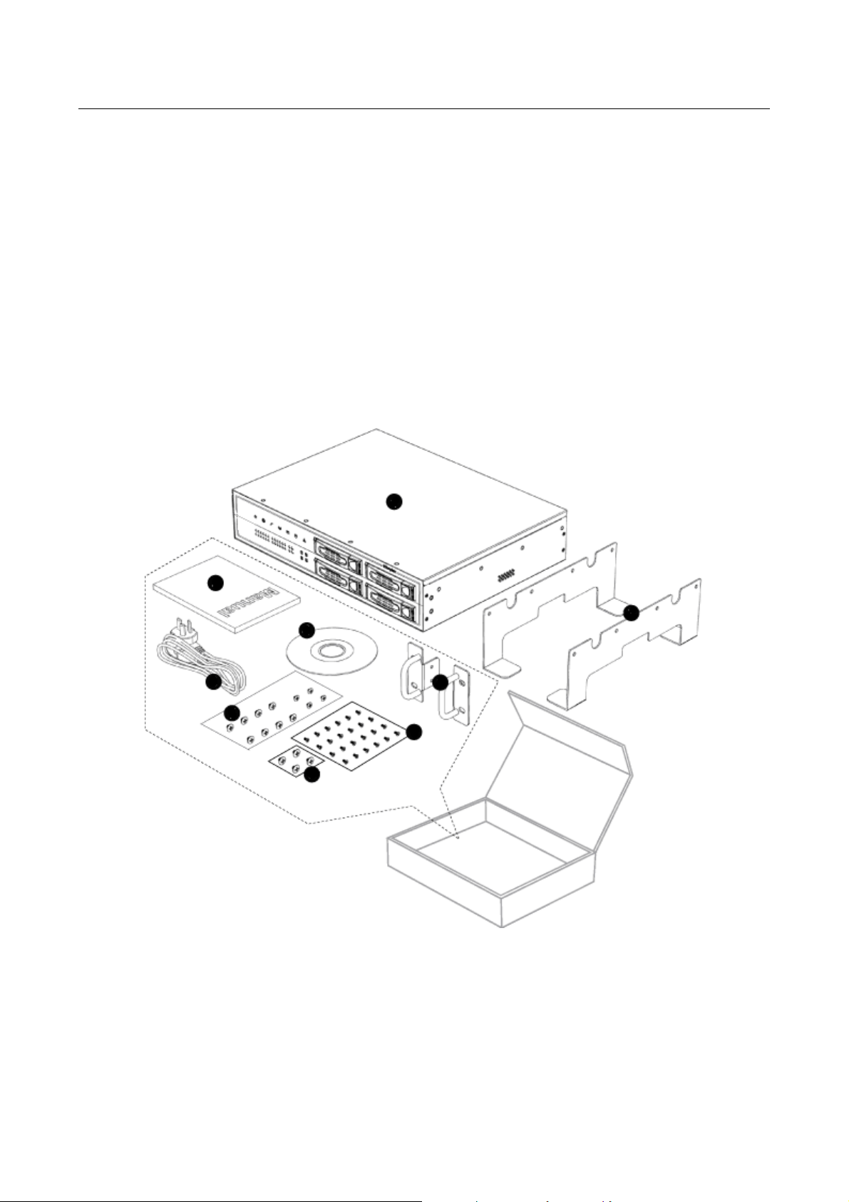
1.2 Package Contents
UMG-2000 / UMG-2200 Unit x 1
AC Power Cord x 1
CD x 1
Quick Installation Guide x 1
Ear Brackets x 2
Desk Brackets x 2
Brackets Fixing Screws x 12
Plug Screws x 4
Disk Carrier Screws x 25
If any of above items are damaged or missing, please contact your dealer immediately.
10
Page 11
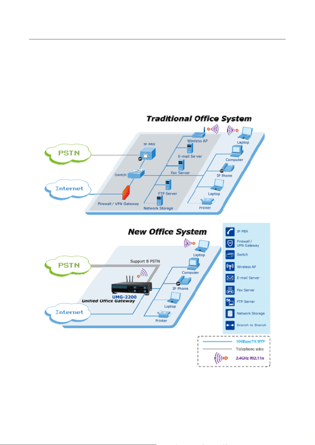
1.3 Application
Highly Integrated IT Services
Providing IP PBX / VoIP, Internet Security, E-mail / FAX Server, Switch, Wireless AP, and
Network Storage service, the UMG-2000 / UMG-2200 features single point of management
to improve IT service ability.
The UMG-2000 / UMG-2200 benefits the SMBs lower cost of ownership, quick and easy
deployment, low noise, space saving and energy conservation for better business
environment.
11
Page 12
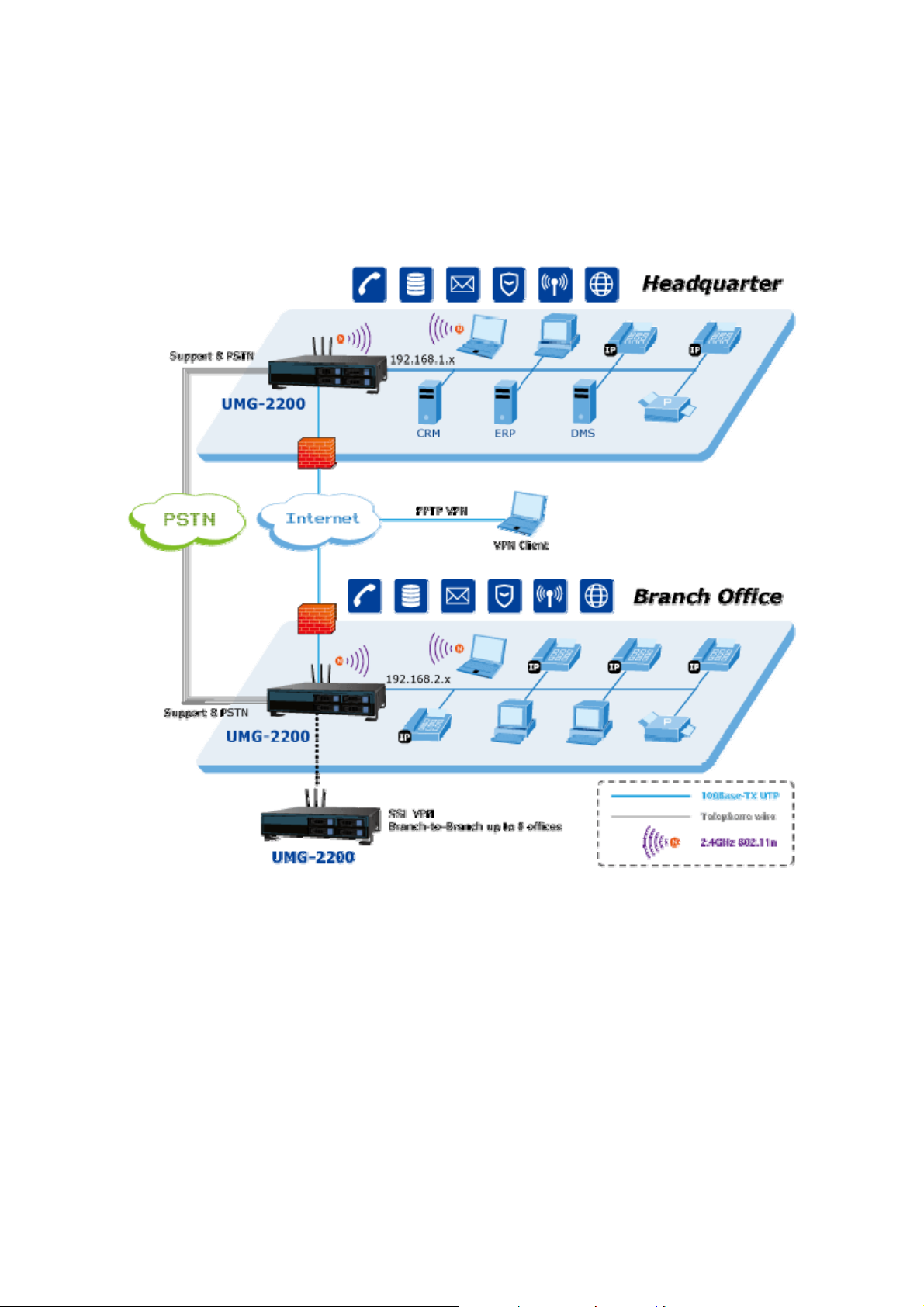
Office Voice and Data Communication
The exchange of business data and voice with high security and superior performance is in
great demand. A secure channel based on SSL VPN is built for data synchronization. A
private voice switching system helps to avoid local or long distance charges by exchanging
voice via a secure Internet tunnel. Additionally, web based remote management makes it
possible to manage all IT resources in your branches without leaving your own office. The
UMG-2000 / UMG-2200 supports Branch-to-Branch up to 8 offices.
12
Page 13
1.4 Outlook
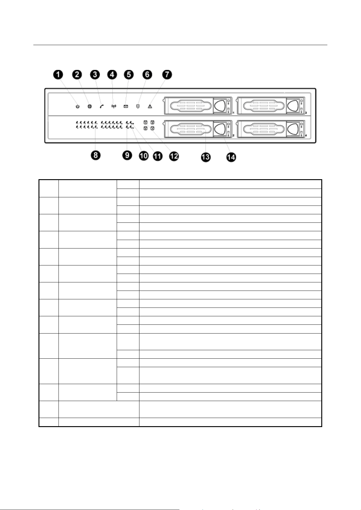
1.4.1 Front Panel
1 PWR LED
2 Internet LED
3 PBX LED
4 WLAN LED
5 E-mail LED
6 Firewall LED
7 Alert LED
8 1~24 LED
9 25~26 LED
10 FTX LED
11 BTB LED
12
Storage 1~4
LED
13 Disk Carrier Handler
14 Disk Carrier switch Press the button to pop out the SATA carrier
On Power On
Off Power Off
On Connect to Internet
Off Disconnect to Internet
On PBX function turn on
Off PBX function turn off
On Wireless function turn on
Off Wireless function turn off
On E-mail function turn on
Off E-mail function turn off
On Firewall/Security function turn on
Off Firewall/Security function turn off
On Don’t insert or pull put hard disk
Off Normal status
On Connect to 1~24 10/100Mbps LAN ports
Off Disconnect to 1~24 10/100Mbps LAN ports
On Connect to 25~26 10/100/1000Mbps LAN ports
Off Disconnect to 25~26 10/100/1000Mbps LAN ports
On
Fault redundant unit is connected and activated (future
feature)
Off Fault redundant unit is not available (future feature)
On Branch to Branch SSL VPN secure link is established
Off
Branch to Branch SSL VPN secure link is not enabled
or disconnected
On Read/Write data in the hard disk
Off Don’t Read/Write data in the hard disk
Push the handler to lock the carrier. Unlock and pull
the hander to get the carrier out
13
Page 14
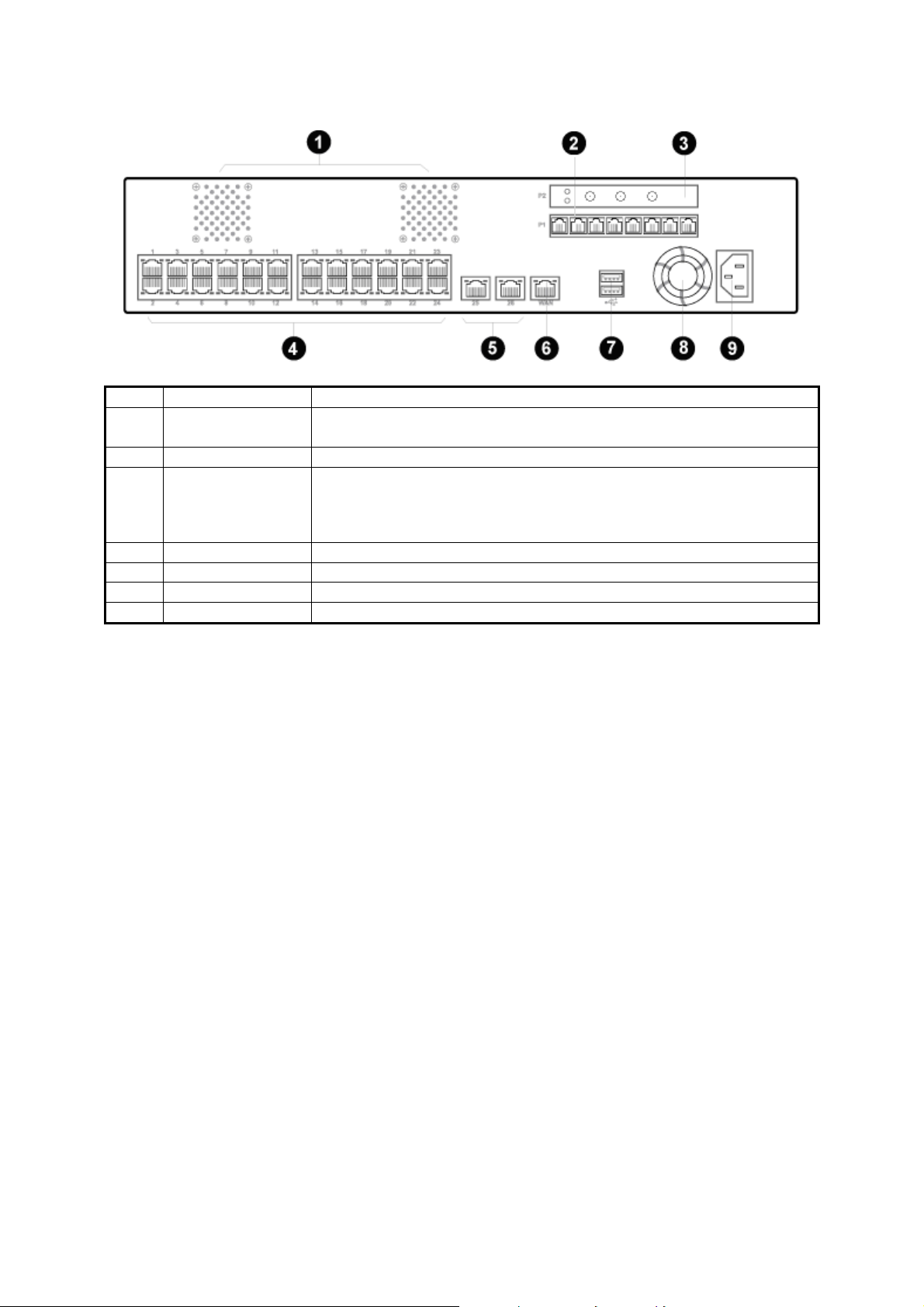
1.4.2 Rear Panel
1 Cooling Fans System cooling fans on rear panel
2 Voice (P1)
3 Wireless (P2) 1 x 802.11b/g/n Wireless Access Point, 3 x Antenna Detachable
4, 5 LAN
6 WAN
7 USB
8 Cooling Fan
9 AC PWR
UMG-2000 : 4 x RJ-11 (4 x FXO)
UMG-2200 : 8 x RJ-11 (8 x FXO)
1~24 ports: 24 x RJ-45 (10/100Base-TX, Auto-Negotiation, Auto
MDI/MDI-X)
25~26 ports: 2 x RJ-45 (10/100/1000Base-T, Auto-Negotiation,
Auto MDI/MDI-X)
1 x RJ-45 (10/100Base-TX, Auto-Negotiation, Auto MDI/MDI-X)
2 x USB2.0 (future feature)
Power supply cooling fan
100~127V AC 6.3A, 200~240V AC 3.0A, 50/60 Hz, 200 Watts
14
Page 15

1.5 Technical Specifications
Hardware Specification
Case 2U high Rack or Desk
WAN 1 x RJ-45 (10/100Base-TX,
LAN
SATA support 4-Port SATA Controller (SATA I, SATA II Hard Disk)
Hard Disk Hot-Swappable SATA Disk (4 x 80GB/160GB/250GB/500GB/1TB)
Voice
Wireless 1 x 802.11b/g/n Wireless Access Point, 3 x RP-SMA Detachable Antenna
USB 2 x USB2.0 (future feature)
LED Indicators
Software Specification
VoIP
IP PBX
2 x RJ-45 (10/100/1000Base-T, Auto-Negotiation, Auto MDI/MDI-X)
24 x RJ-45 (10/100Base-TX, Auto-Negotiation, Auto MDI/MDI-X)
UMG-2000: 4 x RJ-11 (4 x FXO)
UMG-2200: 8 x RJ-11 (8 x FXO)
1 x PWR LED
1 x Internet LED
1 x PBX LED
1 x WLAN LED
1 x E-mail LED
1 x Firewall LED
1 x Alert LED
4 x Storage LEDs
1 x BTB LED
1 x FTX LED
26 x LAN LEDs
SIP protocol
- SIP 2.0 (RFC3261,RFC2833)
Registration
- Factory Default: 50 nodes, Max. 250 nodes
Calls
- Max. 50 concurrent calls
Voice Compression Code Technology
- G.711, G.726, G.723.1 (5.3, 6.3kbps), G.729A (8kbps), GSM
Echo Cancellation
- G.165/G.168
Gain Control
- In/Out +/-6db
Voice Processing
- Voice Activated Detection
- DTMF Detection/Generation
- G.165/G.168 Echo Cancellation (ECN)
- Comfort Noise Generation (CNG)
- Gain Control
- Support call hold, call waiting, 3-way call conference with feature phones
- Built-in in-line call transfer
- Unconditional, unavailable, busy call forward, custom time of no answer
- Per-calling-number forward and rejection
- Group-based call pick-up
- Call-parking
- Inter-PBX SIP trunking
- Multi-room meet-me conference
- Auto-attendant
- Voice mail system
- Call privilege grouping
Auto-Negotiation, Auto MDI/MDI-X
)
15
Page 16

Voicemail
E-mail
Network Storage
Security
Other Protocol /
Function
Management
- FXO interface for PSTN Inbound/outbound
- FXO disconnection tone detection
- Caller ID detection
- In-band/RFC2833/SIP-INFO DTMF translation
- Music on hold (MoH), user upload MoH
- Direct line Outbound
- User upload IVR
- User PIN
- 450 minutes for personal record
- E-mail notification
- Personal reception on unavailability
- Reply call or new call in voicemail menu
Protocol
- POP3,IMAP,SMTP, Web mail
Support accounts
- 250 users
Email Security
- Secured Socket Layer (SSL)
Anti-Virus
- ClamAV
Anti-Spam
Junk mail block
Mailbox size Limit
- 200M/500M/1G/2G/No Limit
Attachment
- 2M/5M/10M/20M/50M/No Limit
Block List
- Share/User/Domain security modes
Email Backup
- Auto-Backup
RAID
- RAID 0, RAID 0/1, RAID 5, JBOD
Date Sharing
- Windows Network Sharing, NFSv3
Network Security
- DoS attack Prevention
VPN Max. connection
- 100 PPTP VPN tunnels
- 8 Site-to-Site SSL VPN tunnels
VPN pass-through
- IPSec, PPTP, L2TP pass-through
Internet Security
- Domain/Keyword Content Filter, Access Control
- IP-MAC Binding
Protocol
- TCP/IP, NAT, DHCP, HTTP, DNS, NTP, HTTPS, CIFS/SMB, NFSv3
LAN
- IEEE 802.1d Spanning Tree
Internet Access
- Static IP, PPPoE, DHCP, PPTP, L2TP
DMZ, UPnP, QoS, DDNS
Multiple host name
- Web based GUI management
- Firmware upgradeable via local
16
Page 17

2. Installation
The followings are instructions for setting up the UMG-2000 / UMG-2200. Refer to the
illustration and follow the steps install your unified office gateway.
2.1 Hardware Installaion
2.1.1 Unpack the UMG-2000 / UMG-2200
Note:
You should inspect the box which the system was shipped in and note if it was damaged in any way
before the unpacking. If the UMG-2000 / UMG-2200 itself shows damage you should file a damage
claim with the carrier to who delivered it. Unpack the UMG-2000 / UMG-2200 as listed below.
2.1.2 Choosing a Setup Location
Decide on a suitable location for the UMG-2000 / UMG-2200 which should be situated in a
clean, dust-free, and well ventilated area. Avoid areas where heat, electrical noise and
electromagnetic fields are generated. Place the UMG-2000 / UMG-2200 near a grounded
power outlet and pay attention to the following requirements.
Leave approximately 40cm (16inche) of clearance in front of the UMG-2000 /
UMG-2200 to ensure the disk carriers can be unplugged.
Leave approximately 30cm (12 inch) of clearance in the back of the UMG-2000 /
UMG-2200 to allow for sufficient airflow and ease in servicing.
17
Page 18

2.1.3 Preparing for Setup
The UMG-2000 / UMG-2200 system was shipped with desk brackets, ear brackets, and
mounting screws, so it is possible to install the UMG-2000 / UMG-2200 into the mounted
rack or on the desk brackets. Please read following sections in its entirety before you begin
the installation and follow the steps in the order given to complete the installation process
correctly.
2.1.4 Precautions
9 Review the electrical and general safety precautions.
9 Install the heaviest server components on the bottom of the rack first, and then work up
if you want to mount the UMG-2000 / UMG-2200 to a rack.
9 Use a power supply regulating uninterruptible (UPS) to protect the server from failure.
9 Allow the hot plug SATA drives and power supply units to cool before touching them.
9 Always keep the rack's front door and all panels and components on the servers
closed when not servicing to maintain proper cooling.
2.1.5 Installation Consideration
Ambient Operating Temperature
If installed in a closed or multi-unit rack assembly, the ambient operating temperature of the
rack environment may be greater than the ambient temperature of the room. Therefore,
consideration should be given to installing the equipment in an environment compatible
with the manufacturer’s maximum rated ambient temperature.
REDUCED AIRFLOW
Consideration should be given to the amount of airflow required for safe operation maybe
not compromised for the rack mounting.
Circuit Overloading
Consideration should be given to the connection of the equipment to the power supply
circuitry and the effect that any possible overloading of circuits might have on over-current
protection and power supply wiring. Appropriate consideration of equipment nameplate
ratings should be used when addressing this concern.
Reliable Ground
A reliable ground must be maintained at all times. To ensure this, the rack itself should be
grounded. Particular attention should be given to power supply connections other than the
direct connections to the branch circuit (i.e. the use of power strips, etc.).
18
Page 19

2.1.6 The Desktop Brackets Installation
Unpack the UMG-2000 / UMG-2200.
The desk brackets have been fixed to the device before packing.
Place the system to appropriate site.
2.1.7 The Rack Mount Installation
It is strongly recommended to securely fasten the mounting rack to the floor or wall to
eliminate any possibility of tipping over the rack. This is especially important if you decide to
install several UMG-2000 / UMG-2200 chassis in the top of the rack.
A brief overview of the UMG-2000 / UMG-2200 installation is as follows:
Select an appropriate site in the rack.
Unload 4 the plug screws from each side of the server.
Mount the ear brackets to the server from the each side.
19
Page 20

Mount the server into the rack.
Lock the server to the rack by mounting the ear brackets to the rack.
20
Page 21

2.1.8 The Hard Disk Installation
The SATA subsystem supports four hot-swappable hard drives. The SATA drives are
inserted to the SATA backplane that provides power and bus termination.
Note:
1. Please install at least one 80G HDD to the No.1 disk carrier before system configurations.
2. If with single HDD, please select RAID level to JBOD.
Locate the storage subassembly.
Press the disk carrier switch to unlock the carrier.
Unplug the disk carrier by pulling the carrier handler.
Mount the disk into the carrier and load the fixing screws.
Press the disk carrier switch to insert the carrier to the disk slot.
Close the disk carrier lock/switch to lock the carrier.
21
Page 22

2.2 Physical Connection
2.2.1 WAN Connection
Locate the WAN port on the rear panel.
Connect the WAN port with the Ethernet cable.
2.2.2 LAN Port Connection
There are 26 Ethernet ports on the rear panel. The port 1 to 24 are 10/100 Mbps
Ethernet ports and the port 25 and port 26 are 10/100/1000 Ethernet ports.
It is recommended to connect the third party switches to the port 25, 26 to expand the
LAN ports.
22
Page 23

2.2.3 PSTN FXO Port Connection
Locate the voice port of the PSTN adapter on the rear panel.
The Analog PSTN port may vary from 4 / 8 FXO ports.
Connect one or more telephone cables to one of the selected FXO port.
23
Page 24

2.3 Quick Setup Wizard
2.3.1 First Time Login
Now that the network connection between your PC and UMG-2000 / UMG-2200 has been
established, you must login in order to access PLANET View.
Launch a web browser (for example: IE, Firefox etc.) and type the UMG-2000 / UMG-2200
IP address in the address bar. The default address is “http://192.168.1.1”.
If you can not see the following login page, recheck your physical LAN connection and
repeat Section 4.2 LAN Connection. To avoid web-based management abused by
unauthorized users, the login sessions will logout automatically if the session is inactive for
more than 5 minutes. Type in an authorized username and password and then click the
button ”Apply”. The default username is “admin”, and its password is “admin” all in lower
case.
24
Page 25

2.3.2 Welcom to Quick Start
After the first login, an easy and short quick start up should be completed to make the
UMG-2000 / UMG-2200 service normally. There is an alternative selection in the page
“Welcome”. One selection is for “Quick Start” and the other is for “Faster Recovery UMG to
UMG” which will be explained in the user’s manual. The quick start includes five steps
which will lead administrator to setup the UMG-2000 / UMG-2200. Check the first radio box
and then click the button “Start” to continue.
Step 1: Create the Company Profile
This page allows an administrator to build a company profile. Specify the profile and then
click the button “Next” to go to step 2.
25
Page 26
Item Description
Company Specify your company name.
Location Specify your city name.
Country Specify your country name.
Time Zone Specify the time zone.
PBX Extension
Specify the prefix of the extensions. All PBX extensions will be
prefixed with this number. (X=0~9).
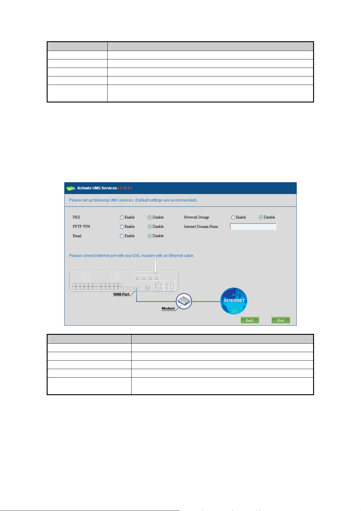
Step 2: Activating UMG-2000 / UMG-2200 services
The UMG-2000 / UMG-2200 allows the administrator to activate the service on demand. By
default, all services are inactive. The administrator can activate the service in this page by
checking the radio box of the corresponding service. The activated services will start up by
using the default configuration after the quick start. Click the button “Next” to go to step 3.
Item Description
PBX Enable or disable the IP PBX service.
PPTP VPN Enable or disable the PPTP VPN service.
Email Enable or disable the Email service.
Network Storage Enable or disable the network storage service.
Internet Domain Name
Specify a valid Internet domain for the email server if
the email service is enabled.
26
Page 27
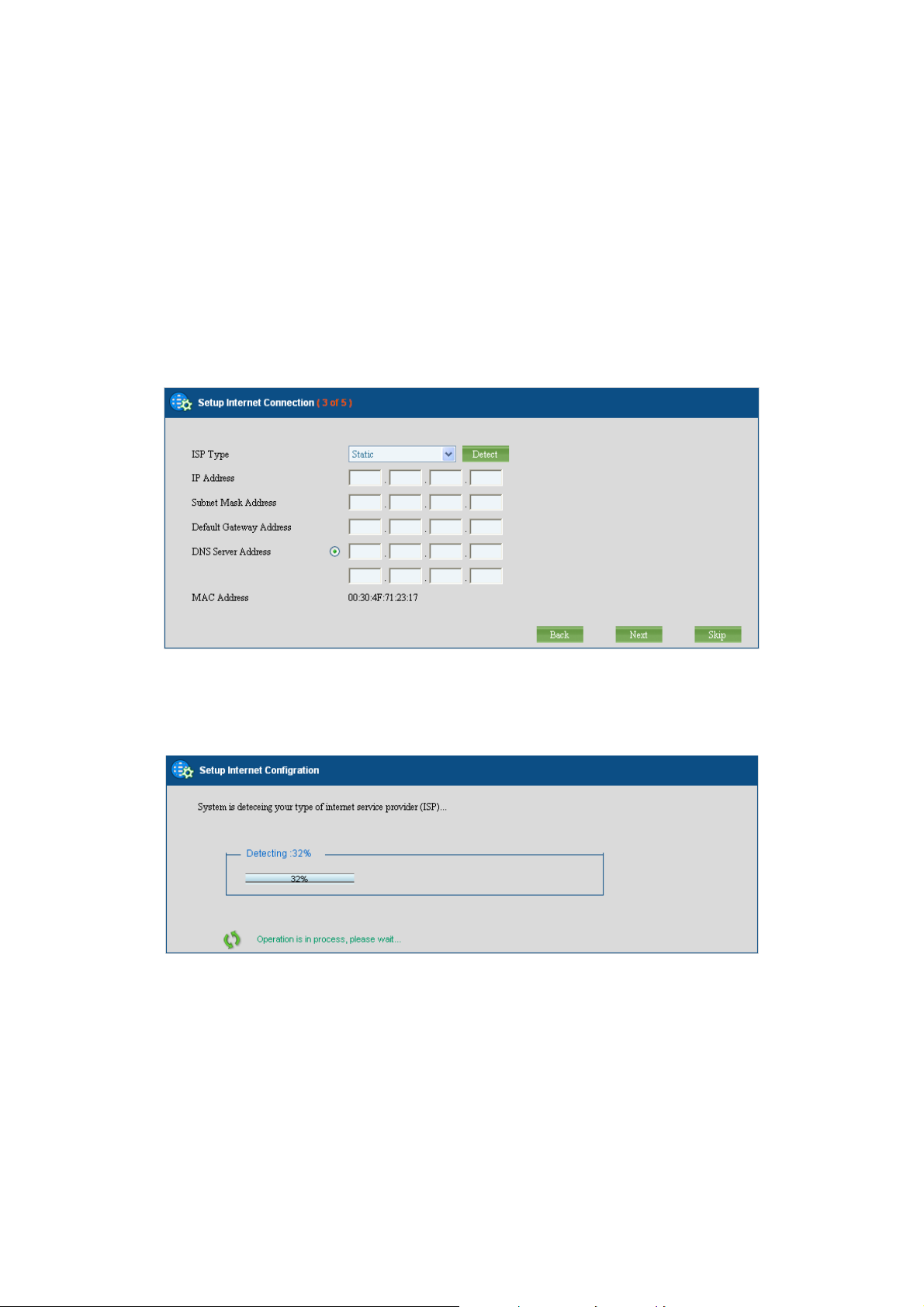
Step 3: Setting up the Internet Connection
This page allows the administrator to quickly setup the WAN connection. To setup the
Internet connection, you should be awarded of what method you are using to connect to the
Internet. All technical information should be provided by your Internet Service Provider
(ISP). The ISP type should be one of the followings: static, DHCP, PPPoE or PPTP. Select
your ISP type in the drop down menu. Specify the Internet connection configuration and
then click the button “Next” to go to step 4 or click the button “Skip” to skip this step.
AUTO DETECT ISP TYPE
By clicking the button “Detect”, you can make the UMG-2000 / UMG-2200 to recognize the
ISP type automatically.
It may take a while to detect your ISP type. Please wait.
27
Page 28

The ISP type will be detected and the result will be presented as follows. If “Network Cable
Disconnected” is detected, please recheck the physical connection and repeat the action as
shown in Section “WAN Connection”. There could be more than one ISP type recognized,
so choose the most suitable type from the list and then click the button “Next” to continue.
MANUAL SETUP INTERNET CONFIURATION: STATIC
If your ISP type is “Static”, choose it as your ISP type and setup the configuration.
Item Description
IP Address Specify the static IP address.
Subnet Mask Address Specify the subnet mask address.
Default Gateway Address Specify the IP address of the default gateway.
DNS Server Address
Specify the IP address of the primary and secondary
Domain Name System.
MAC Address Show MAC address information.
28
Page 29
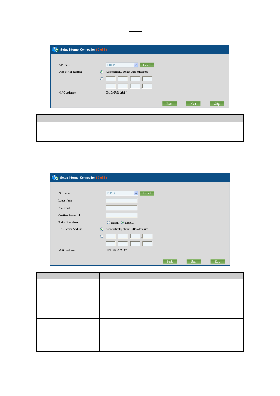
MANUAL SETUP INTERNET CONFIURATION: DHCP
If your ISP type is “DHCP”, choose it as your ISP type and setup the configuration.
Item Description
DNS Server Address
Automatically obtain the DNS address or specify the IP
address of the primary and secondary DNS server.
MAC Address Show MAC address information.
MANUAL SETUP INTERNET CONFIURATION: PPPOE
If your ISP type is “PPPoE”, choose it as your ISP type and setup the configuration.
Item Description
Login Name Specify the login username to the PPPoE server.
Password Specify the login password to the PPPoE server.
Confirm Password Retype the password.
Static IP Address Specify whether you have a static IP address.
IP address
Subnet Mask Address
DNS Server Address
Specify your static WAN IP address if you have enabled
the “Static IP Address”.
Specify the subnet mask address if you have enabled
the “Static IP Address”.
Automatically obtain the DNS address or specify the IP
address of the primary and secondary DNS server.
MAC Address Show MAC address information.
29
Page 30
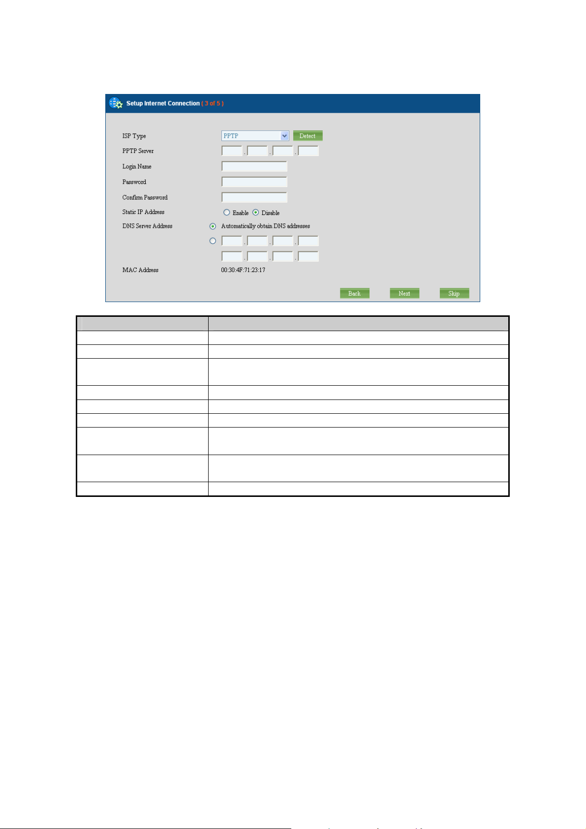
MANUAL SETUP INTERNET CONFIURATION: PPTP
If your ISP type is “PPTP”, choose it as your ISP type and setup the configuration.
Item Description
PPTP Server Specify the PPTP server IP address.
Login Name Specify the username to login to the PPTP server.
Password
Specify the corresponding password to login to the
PPTP server.
Confirm Password Retype the password.
Static IP Address Specify whether you have a static WAN IP address.
IP address Specify whether you have a static IP address.
Subnet Mask Address
DNS Server Address
Specify your static WAN IP address if you have enabled
the “Static IP Address”.
Specify the subnet mask address if you have enabled
the “Static IP Address”.
MAC Address Show MAC address information
30
Page 31
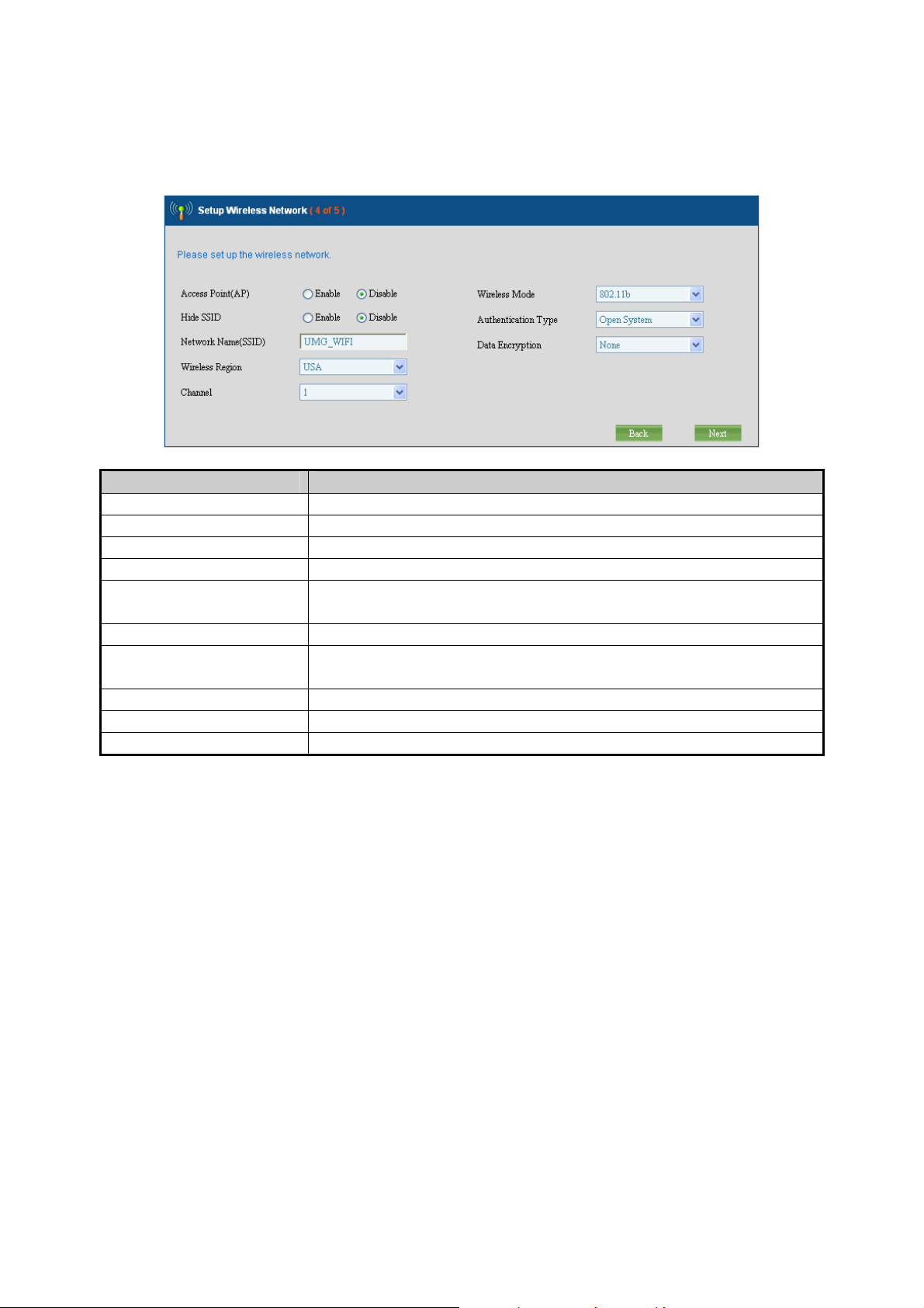
Step 4: Setting the Wireless Network
This page allows the administrator to quickly setup the wireless Access Point (AP). Specify
the wireless configuration and then click the button “Next” to go to step 5.
Item Description
Access Point (AP) Enable or disable the wireless AP service.
Hide SSID Decide whether or not to make the wireless AP SSID visible.
Network Name (SSID) Specify the preferred SSID name string.
Wireless Region Select the area of location yours.
Wireless Mode
Select the preferred wireless AP mode:
802.11b / 802.11g / 802.11n.
Channel Select the preferred wireless channel number.
Authentication Type
Specify the authentication type:
Open system / Shared Key / WPA / WPA2.
Data Encryption Select the Data Encrypt type.
Encrypt Strength Select the encrypt strength.
Security Key Specify the key for the clients to access this AP.
31
Page 32

Step 5: Creating the Network Storage
This page allows the administrator to quickly setup the storage. Specify the Redundant
Array of Independent Disks (RAID) level and then click the button “Next” to go to step 6.
Step 6: Confirmation
Please recheck your input data to ensure the accurate. Click the button “Back” to make
changes. Then confirm your data and wait for the accomplishment of the wizard. It will take
a couple of minutes. Please “do not” close the browser. The browser will show the RAID
building progress. After finishing the wizard successfully, the page of “Personal Account
Web Administration” will automatically appear.
32
Page 33

3. Web Management - Home
UMG-2000 / UMG-2200 provides a basic chassis as the hardware platform, back-end
service control software and front-end web-based GUI management tool PLANET View.
This chapter gives a general description of UMG-2000 / UMG-2200.
3.1 Overview
The “Overview” screen presents the UMG-2000 / UMG-2200 system service status
summary in one convenient location. You can quickly and efficiently view the important
details of the system status, service state, and environment condition.
HEADER
Welcome: Displays the effective user ID.
Company: Displays the company name.
Location: Displays the location.
SYSTEM STATUS
This section lists the system status of UMG-2000 / UMG-2200, including the
current system information and the software, hardware versions.
Software Version: Displays the software running version number.
Hardware Version: Displays the hardware version.
Internet domain Name: Displays the Internet Domain Name configuration.
Storage Workgroup Name: Displays the Workgroup name of the Network
Storage.
Deploy Mode: Displays the deployment mode: Standalone, Headquarter, or
Branch mode.
System Uptime: Displays the total uptime since the last reboot.
Last Reboot Time: Displays the last system reboot time.
Current Date: Displays the current date.
Temperature: Display the current system internal temperature.
CPU Usage: Displays the current CPU utilization rate.
33
Page 34

UMG SERVICE
This section lists the state and status of all the IT services.
PBX: Displays the state (enable or disable) and status (up or down) of VoIP
service.
Wireless: Display the state (enabled or disabled) and status (up or down) of WiFi
service.
Email: Displays the Email service state (enabled or disabled) and its status (up
or down).
Firewall: Displays the Firewall service state (enabled or disabled) and its status
(up or down).
Storage: Displays the storage service state (enabled or disabled) and its status
(up or down).
PPTP VPN: Displays the VPN service state (enabled or disabled) and its status
(up or down).
Alert: Displays the current system alert state, enabled or normal.
NETWORK CONNECTION
This section shows the current status of all the physical network links.
Port 1-24: Displays the physical link state of the 10/100 Mbps ports, connected
or disconnected.
Port 25: Displays the physical link state of the 10/100/1000 Mbps network port,
connected or disconnected.
Port 26: Displays the physical link state of the 10/100/1000 Mbps network port,
connected or disconnected.
WAN: Displays the physical link state of the 10/100 Mbps WAN port state,
connected or disconnected.
34
Page 35

3.2 Spanning Tree Protocol
Spanning Tree Protocol (STP) is a link management protocol that provides path
redundancy while preventing undesirable loops in the network. For an Ethernet network to
function properly, only one active path can exist between two stations. The UMG-2000 /
UMG-2200 uses STP on the switch (Port 1 to Port 26) to detect the loop link. If the loop
occurs, the information will be presented in the “Overview” page. Then, unplug the
indicated cable and check your physical Ethernet link.
3.3 Alert Log
The screen displays the UMG-2000 / UMG-2200 alert log list. If the administrator has
assigned the alert email address, the messages will be sent to the added email address.
Date: Displays the date of the alert log.
Time: Displays the time of the alert log.
ID: Displays the alert log ID.
Description: Displays the detail description of the alert Log.
35
Page 36

4. Web Management - User
The UMG-2000 / UMG-2200 provides a user based service provisioning with secured
access control based on the given privilege.
GROUP MANAGEMENT
Group management allows the administrator to organize groups and departments similar to
the organization of your company and assign different privileges to different groups. It
creates a more efficient way of managing and controlling large numbers of users.
USER MANAGEMENT
User management allows the administrator to manage the user profile. Based on the profile,
the data and services of this user can be created, updated or deleted. An user provisioning
services include email, voice, remote access VPN, and network storage.
4.1 User Overview
The administrator can get the overview of all the available users’ profile including a brief
introduction in the “Overview” page. To get more detailed information on a specific user,
click the corresponding user name. (Refer to Section - Updating the User Setting.) The
administrator can also delete or temporarily suspend the user’s access by checking the
radio box and clicking the “delete” button. (Refer to Section - Delete a User Account.)
USER LIST
This section lists all the available user information:
Username: Displays a user name.
Department: Displays the department which the specific user belongs to.
Email: Displays the email service status of the user.
PPTP VPN: Displays the PPTP VPN status of the user.
Extension: Displays the VoIP phone number of the specific user.
Call Privilege: Displays the call privilege of the specific user.
Quota: Displays the maximum quota of the specific user.
36
Page 37

4.2 Deleting a User Account
Check the radio box and click the “delete” button. You can delete or disable the specific
user account. Disabling the user account will freeze all user services without damaging the
profile and data of the user. Deleting the user account will clear the entire data and profile of
the user. If you want to freeze this account for a period of time, check the “Disable the user
account” check box and confirm. If you want to delete the user, check the “Delete all the
user’s data” check box and confirm.
Note:
Delete all user account data, the user’s email, voice, private data and profile will be deleted.
Please backup the data first.
4.3 Updating the User Setting
Click the username that you want to update in the “Overview” page, and the detailed user
profile will appear. Change the user profile and then click the “Apply” button to update the
user setting.
37
Page 38

4.4 Creating a User Account
To create a new user account, click the “User” tab in the “User” screen. This screen allows
the administrator to create a new user profile with specified service privileges.
USER ACCOUNT:
This section lists all the available settings of the user profile:
User name: Specifies a user name. All user related IT services will be created
based on this name. It cannot be changed once set.
Full Name: Specifies the user’s full name.
Password: Specifies the user’s access password. This password will be applied
to all the user related services, too.
Confirm password: Confirms and verifies the entered user password.
Account Type: Specifies either a common user or admin user privilege. The
user with the admin privilege can access the GUI management pages to manage
the UMG-2000 / UMG-2200 except the storage service.
Account Status: Indicates whether the user account is in an active or
suspended state. Active: all user subscribed IT services can be optionally
enabled. Suspended: all user subscribed IT services are disabled.
Department: Indicates a proper group or department for the user. You can create
a new group or department by clicking the “Group” tab from the “User” screen.
User ID: Specifies a unique user identifier for the user. The default value is
recommended.
38
Page 39

USER SERVICES:
This section lists all the available settings of the user services:
Email: Allows or denies user Email services.
PPTP VPN: Allows or denies a user’s VPN remote access privileges.
Private Storage: Allows or denies a user’s local storage access.
Storage Quota: Specifies the maximum user quota.
IP PBX phone privilege: Allows or denies a user’s VoIP phone access.
Disable: Denies a user’s VoIP phone access.
Local: Allows the user to dial a local external phone.
National: Allows the user to dial a national external phone.
International: Allows the user to dial an international external phone.
Extension: Specifies the VoIP phone number of the specific user which starts
with the local dial prefix. It must be specified if the IP PBX phone privilege is not
disabled and it cannot be changed once applied.
Voice Mail Password: Specifies the password that is used to access the voice
mail. It must be specified if the IP PBX service is enabled.
4.5 Departments and Groups
You may assemble your defined users into different groups based on different criteria. To
add a new group, click the “Group” tab. The “Group Settings” screen will then appear.
GROUP SETTING
This section lists all the available settings of the group:
Group ID: Specifies the group unique identifier. The default group ID is
recommended.
Group Name: Specifies a name for the group i.e. sales, marketing, or operation.
GROUP LIST
This section lists available group information:
Group ID: Displays the group ID.
Group Name: Displays the group name.
39
Page 40

4.6 Deleting a Group
Check the check box “delete” and click the “Apply” button to delete a group.
Note:
You must delete all the members within the group before you delete the group.
40
Page 41

5. Web Management - Network
The UMG-2000 / UMG-2200 network management suite provides the administrator the
ability to co figurate Internet service, Local Area Network services, FTP control services,
NTP service and network storage security services.
INERNET Configuration
The UMG-2000 / UMG-2200 provides 10/100Mbps WAN ports as the internet interface and
supports static IP, DHCP, PPTP and PPPoE as the ISP type. Internet management
provides the ability for the administrator to manage the configuration of the Internet
interface. The UMG-2000 / UMG-2200 can also works as the gateway which connects the
Internet and the LAN and determines where to direct the package of data that arrive at the
UMG-2000 / UMG-2200.
LAN Configuration
A Local Area Network (LAN) is a high-speed communications system designed to link
computers and other data processing devices to share vital computing resources, such as
printers, files etc. The UMG-2000 / UMG-2200 provides 24x4 10/100 Mbps and
2x10/100/1000 Mbps ports for LAN switching. The UMG-2000 / UMG-2200 also provides
the Spanning Tree Protocol (STP) to prevent undesirable loops in the network.
NETWORK SERVICES Configuration
The UMG-2000 / UMG-2200 provides many network services, including FTP, DNS, SAMBA,
NTP, DHCP etc. Network services management allows for the ability to manage the
configuration of these services.
5.1 Overview
The administrator can get the overview of the network settings and the status of the
network services.
41
Page 42

INTERNET SETTING:
This section lists the current settings of the Internet:
ISP Type: Displays the ISP type.
IP Address: Displays the IP address of the WAN port of UMG-2000 / UMG-2200.
Subnet Mask Address: Displays the subnet mask address.
Default Gateway Address: Displays the IP address of the default gateway.
Primary DNS Address: Displays the primary DNS address.
Secondary DNS Address: Displays the secondary DNS address.
Internet Link Speed: Displays the maximum speed of the Internet link.
LOCAL NETWORK SETTING
This section lists all the current settings of LAN:
Connected Users: Displays the number of users that have been connected to
the UMG-2000 / UMG-2200.
Local Server Address: Displays the LAN IP address of the UMG-2000 /
UMG-2200.
Subnet Mask Address: Displays the LAN subnet mask address.
DHCP Server: Displays the state of the DHCP server, enabled or disabled.
DHCP Range Start Address: Displays the start address of the DHCP IP range.
DHCP Range End Address: Displays the end address of the DHCP IP range.
Local Network Link Speed: Displays the maximum speed of the LAN link.
INTERNET SERVICES
This section lists the service state of the WAN services:
Internet Domain Name: Displays the Internet domain name.
DNS Server: Displays the state of the DNS service, enabled or disabled.
Email Server: Displays the state of the email service, enabled, or disabled.
PPTP VPN Server: Displays the state of the PPTP VPN server, enabled or
disabled.
Network Storage: Displays the state of the network storage service (SAMBA),
enabled or disabled.
LOCAL NETWORK SERVICES
This section lists the service state of the LAN services:
Domain Controller: Displays whether the UMG-2000 / UMG-2200 is the domain
controller.
Domain Work Group: Displays the Windows workgroup that UMG-2000 /
UMG-2200 belongs to.
NTP Server: Displays the state of the NTP server, enabled or disabled.
42
Page 43
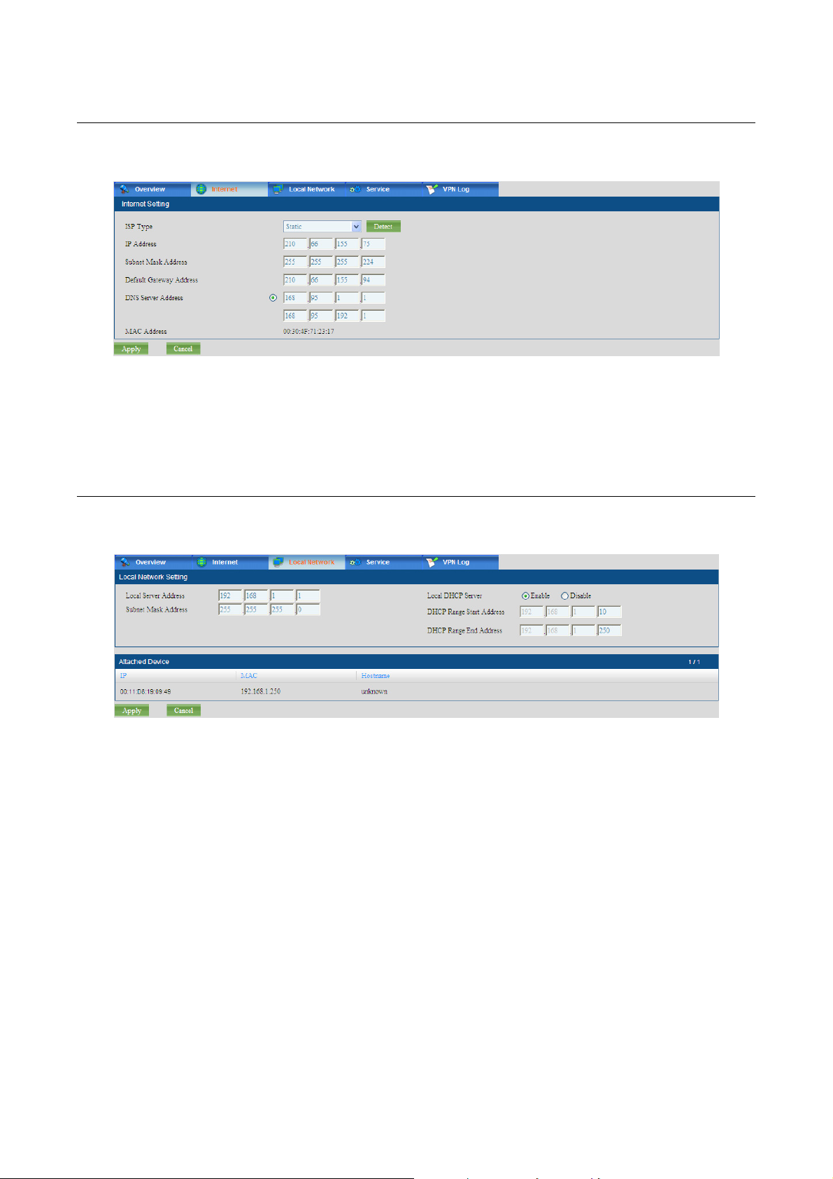
5.2 Internet
The “Internet” screen allows the administrator to change the Internet settings.
5.3 Local Network
The “Local Network” screen allows the administrator to change the Internet settings.
LOCAL NETWORK SETTING
This section lists all the available settings of the LAN:
Local Server Address: Specifies the LAN IP address of the UMG-2000 /
UMG-2200
Subnet Mask Address: Specifies the LAN subnet mask address.
DHCP Server: Specifies the state of the DHCP server, enabled or disabled.
DHCP Range Start Address: Specifies the start address of the DHCP IP range.
DHCP Range End Address: Specifies the end address of the DHCP IP range.
43
Page 44

5.4 Service
The “Service” screen allows the administrator to change the setting of the network services.
INTERNET SERVICES
This section lists all the available settings of the WAN services:
Internet Domain Name: Specifies the Internet domain name.
PPTP VPN Server: Enables or disables the PPTP VPN service.
Network Storage: Enables or disables the network storage server (SAMBA)
service.
LOCAL NETWORK SERVICES
This section lists all the available settings of the LAN services:
Domain Work Group: Specifies the UMG-2000 / UMG-2200 Windows workgroup.
NTP Server: Enables or disables the NTP service.
5.5 The VPN Log
The “VPN Log” screen allows the administrator to trace the VPN logging history. The
administrator can also search by using the login ID to find the user’s VPN history.
VPN Log
This section lists the VPN logging history:
Date: Displays the date of the log.
Time: Displays the time of the log.
Source IP: Displays the client WAN IP
Assign IP: Displays the IP address that the server has assigned to the client.
Login: Displays the effective login ID of the client.
Event: Displays the detail description of the Log.
44
Page 45

6. Web Management - Wireless
The UMG-2000 / UMG-2200 wireless suite integrates the following services: standard
access point (AP), multiple layers of wireless security and client blocking.
STANDARD WIRELESS ACCESS POINT
The UMG-2000 / UMG-2200 supports three task groups in 802.11 standard working groups:
802.11b/g/n. 802.11b supports data rates up to 11 Mbps, 802.11g supports data rates of at
least 20 Mbps and 802.11n supports up to 300Mbps / 2T3R.
ENCRYPTION and Security
A wireless client will connect and join the network if no encryption is enabled. However, the
encryption greatly enhances the security of the connection and data transmission between
the access point and the wireless client. This includes the IEEE 802.1x port-based
authentication protocol, Wireless Protected Access (WPA),Wireless Protected
Access –version 2 (WPA2,) Wireless Encryption Protocol (WEP). If WEP is chosen as the
encrypt method, each packet is composed of the 24 bits Initialization vector and 40/104 bits
encryption. Therefore, WEP encrypt length will be 64bits or 128 bits. WEP uses the RC4
stream encryption (a fresh key stream for each package). WEP, with minimal flaws, is
enough to prevent most hacking. At the same time, WEP will cause often a 20-50%
reduction of the wireless speed. WPA is an interim solution until the 802.11i comes out. It
also uses the RC4 with the key changed to TKIP. TKIP works by generating a sequence of
WEP keys based on a master key and re-keying periodically.
CLIENT BLOCKING
The wireless is the opening network system for the wireless clients and any authenticated
clients can access the Wireless LAN (WLAN). However, the wireless AP can monitor the
status of the connected clients and set access limitation to the clients. To temporarily block
client access, the administrator can add the client MAC to the clock list. The client cannot
connect to the AP unless the administrator releases the blocking.
45
Page 46
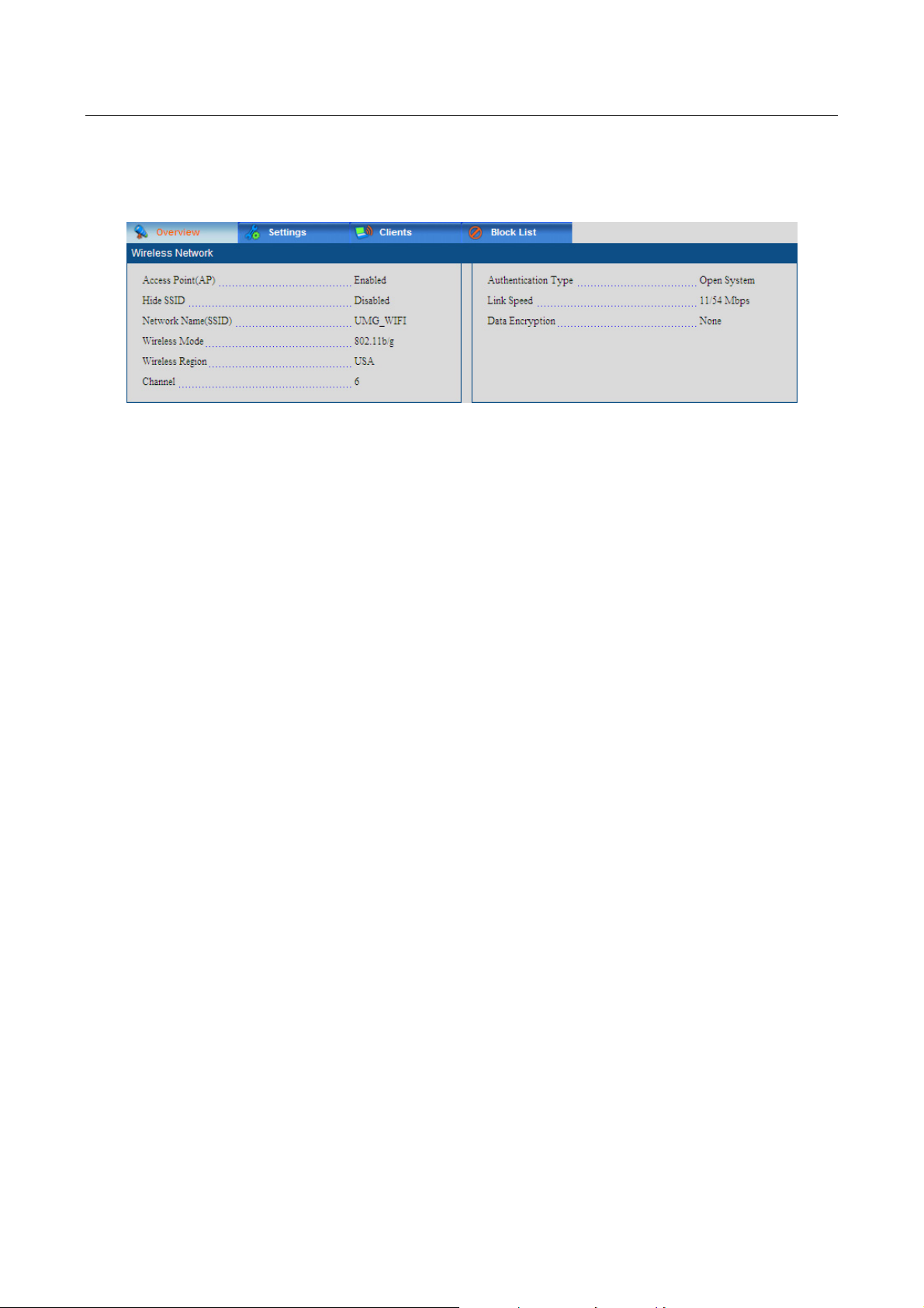
6.1 Overview
The wireless “Overview” screen presents the current wireless services status summary.
The administrator can quickly view important details of your wireless Access Point services
(AP) status.
WIRELESS NETWORK
This section lists all the current settings of the wireless Access Point (AP).
Access Point: Displays the wireless AP service state, enabled or disabled.
Hide SSID: Displays the visibility of the wireless AP SSID.
Network Name (SSID): Displays the SSID of this wireless network.
Wireless Mode: Displays the wireless AP supporting mode.
Wireless Region: Displays the region that the wireless AP belongs to.
Channel: Displays the current channel configuration mode: auto or channel
number
Authentication type: Displays the current wireless AP security access type.
Link speed: Displays the wireless AP link speed.
Data Encryption Type: Displays the type of data encryption.
Encrypt Strength: Displays the encrypt strength if WEP is the data encryption
type.
Security Key: Displays the key for the clients to access this AP if WEP is the
data encryption type.
46
Page 47
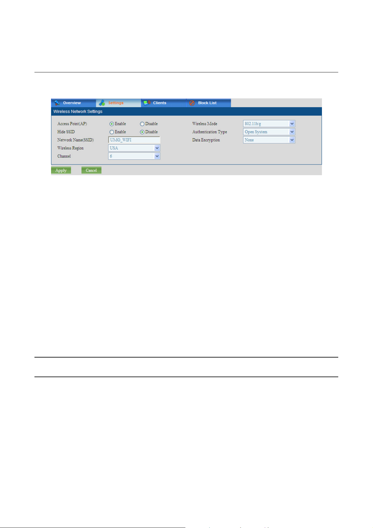
6.2 Wireless Setting
The wireless “Setting” screen enables the administrator to manage the wireless AP.
WIRELESS NETWORK
This section lists all the available settings to the wireless Access Point (AP). Service is only
accessible when enabled. SSID is visible and can be scanned only when “Hide SSID” is
disabled.
Access Point: Enables or disables the wireless AP service.
Hide SSID: Specifies whether the wireless AP SSID is visible or not.
Network Name (SSID): An SSID is the name of a wireless local area network
(WLAN). Specifies the preferred SSID name string.
Wireless Region: Specifies the region that the wireless AP belongs to. The
region will affect the channels and the working frequency of your AP.
Wireless Mode: Specifies the preferred wireless AP mode.
Channel: Specifies a preferred wireless channel number or an auto channel.
Authentication Type: Specifies the authentication type.
Data Encryption: Specifies the type of Data Encrypt.
Encrypt Strength: Specifies the encrypt strength if WEP is the data encryption
type.
Security Key: Specifies the key for the clients to access this AP if WEP is the
data encryption type.
Note:
You cannot detect the AP if “Hide SSID” is enabled.
47
Page 48

6.3 Wireless Clients
The wireless “Clients” screen shows the wireless clients current connection to the
UMG-2000 / UMG-2200 wireless Access Point (AP). Each connected wireless clients
information is listed in a tabulated form. The following are the wireless client connection
information.
WIRELESS CLIENT
This section lists the current information on the connected wireless clients.
MAC Client: Displays the MAC Address of the wireless client.
IP Address: Displays the IP Address of the wireless client.
Hostname: Displays the host name of the wireless client.
Channel: Displays the connected channel number.
Rate: Displays the data transfer rate.
6.4 Blocking the Connected Wireless Client
The administrator can block any connected wireless client by clicking the “block” button.
The selected wireless client will be blocked and access will be denied.
48
Page 49

6.5 Wireless MAC Block List
The wireless “Block List” screen displays the current block list. The administrator can
unblock any or all of the computers currently prohibited to access the shared resources
through the wireless AP.
CREATE NEW RULE
This section lists the settings to block a wireless client to access the wireless AP.
MAC Address to Block: Specifies the MAC address to block.
ACCESS BLOCK LIST
This section lists all the currently blocked wireless clients to the wireless AP.
MAC: Displays the MAC address in the block list.
ADD TO THE BLOCK LIST
The administrator can add a new MAC address to the block list by filling in the client MAC
address and clicking the “Apply” button. The client with the newly added MAC address
cannot access this AP any more.
REMOVE FROM THE BLOCK LIST
The administrator can remove a selected MAC address from the block list by checking the
corresponding checkbox and clicking the “Apply” button. The unblocked client with the MAC
address can then access the wireless AP again.
49
Page 50

7. Web Management - Storage
The UMG-2000 / UMG-2200 storage suite includes the following services: Redundant Array
of Independent Disks (RAID), Network Storage Server, backup/restore, and remote data
synchronizing.
RAID AND JBOD
The UMG-2000 / UMG-2200 supports RAID on storage devices. A RAID device is a logical
device that has physical devices underlying it. These physical devices are disk partitions.
The supported RAID levels are:
Level 0:
Provides data striping, or the spreading out of blocks of each file across
multiple disk drives but without redundancy. This improves performance but
does not deliver fault tolerance. If one drive fails then all data in the array is lost.
Level 0+1:
RAID 0+1 is a mirrored configuration of two striped sets. This is a technique in
which data is written to two duplicate disks simultaneously, providing data
redundancy.
Level 5:
Provides data striping and utilizes one disk for backup information, which
enables it to restore any other disk in the array.
On top of the RAID, the UMG-2000 / UMG-2200 supports Logical Volume Management
(LVM2) that provides a higher-level view of the disk storage on a computer system than the
traditional view of disks and partitions. This gives the system administrator much more
flexibility in allocating storage to applications and users. Storage volumes created under the
control of the LVM can be resized and relocated. The LVM also allows management of
storage volumes in user defined groups, allowing the system administrator to deal with
sensibly named volume groups.
Another choice other than RAID is the technology of “Just a Bunch Of Disks” (JBOD). The
RAID system stores the same data redundantly on multiple disks that nevertheless appear
to the operating system as a single disk. Although, JBOD also makes the disks appear to
be a single one, it accomplishes that by combining the drives into one larger logical disk.
JBOD doesn’t deliver any advantages over using separate disks independently and doesn’t
provide any of the fault tolerance or performance benefits of RAID.
NETWORK STORAGE SERVER
The UMG-2000 / UMG-2200 supports Server Message Block (SMB), also known as
Common Internet File System (CIFS) to share files on the private network which can be
used for WINDOWS, Linux/Unix and other operating systems and Network File System
(NFS) clients/servers.
50
 Loading...