

Page 1

Unied Ofce Gateway
UMG-1000 / UMG-1000W
Quick Installation Guide
Page 2

Table of Contents
1. Package Contents ........................................................................................ 3
2. Overview .................................................................................................... 4
3. Hardware Installation ................................................................................... 5
3.1 Removing the Chassis Cover .................................................................. 5
3.2 The Hard Disk Installation ..................................................................... 5
4. Physical Connection .................................................................................... 10
4.1 WAN Connection ..................................................................................10
4.2 LAN Port Connection ............................................................................10
4.3 PSTN FXO Port Connection....................................................................11
5. Quick Setup Wizard ....................................................................................12
5.1 First Time Login ...................................................................................12
5.2 Welcome to Quick Start ........................................................................12
Further information .........................................................................................20
Page 3

1. Package Contents
UMG-1000 / UMG-1000W Unit x 1 l
AC Power Cord x 1 l
CD x 1 l
Quick Installation Guide x 1 l
HDD accessories package x 1 l
RJ-45 to RS-232 Console cable x 1 l
Antennas x 2 (UMG-1000W) l
If any of above items are damaged or missing, please contact your dealer
immediately.
3
Page 4
4
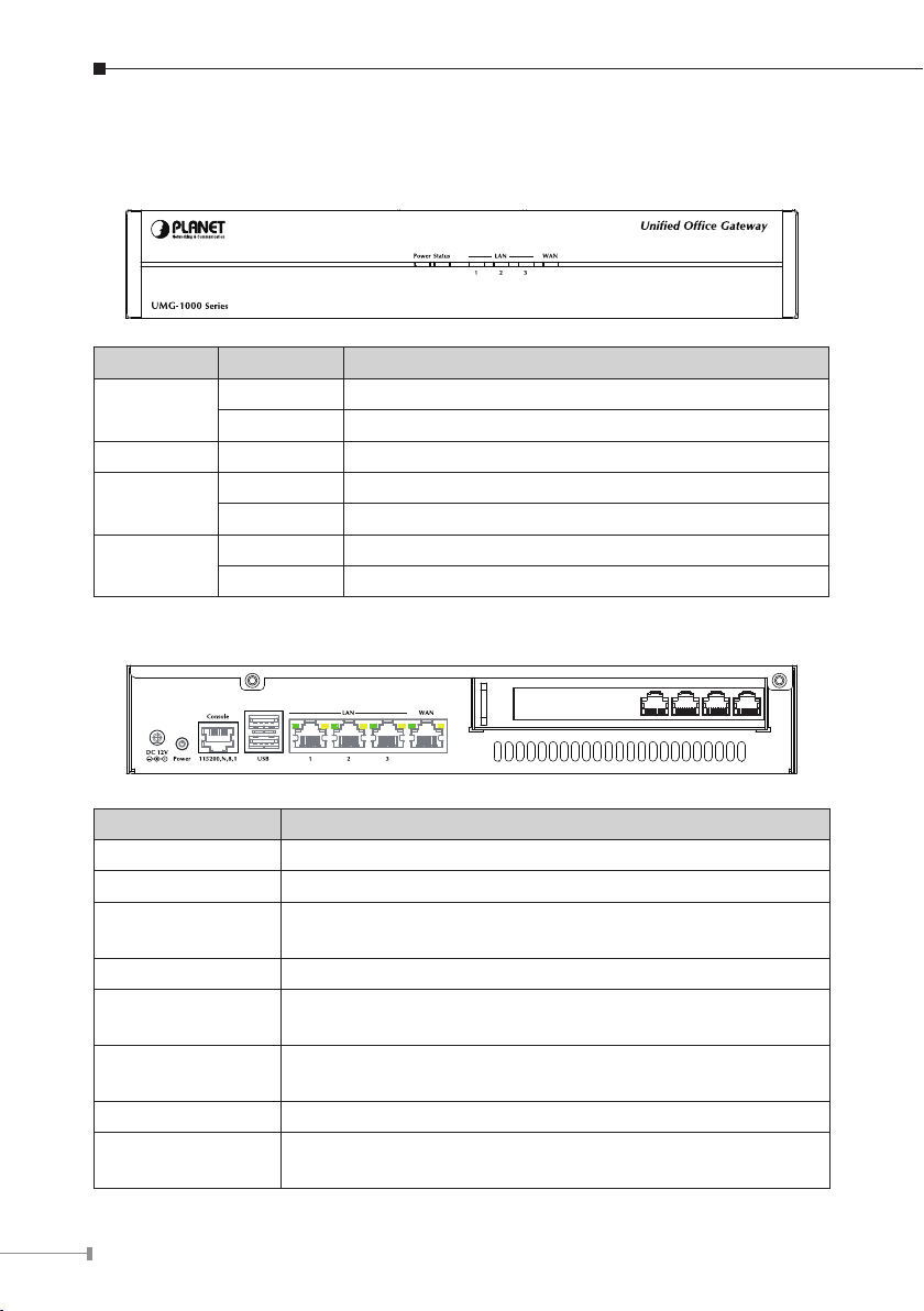
2. Overview
Front Panel
LED ON/OFF Description
Power
Status Flash System operating
WAN
LAN
Rear Panel
On Power On
Off Power Off
On Connect to WAN port
Off Disconnect to WAN port
On Connect to 1~3 LAN ports
Off Disconnect to 1~3 LAN ports
Port Description
DC 12V DC 12V, 3.75A
Power Power ON/OFF button
Console
USB 2 x USB2.0 (future feature)
LAN
WAN
Voice 4 x RJ-11 (4 x FXO)
Antenna
(For UMG-1000W)
Use RJ-45 to RS-232 console cable for engineer
maintenance (future feature)
3 x RJ-45 10/100/1000Base-T, Auto-Negotiation, Auto MDI/
MDI-X
1 x RJ-45 10/100/1000Base-T, Auto-Negotiation, Auto MDI/
MDI-X
Used to connect the external antenna for 802.11b/g/n
wireless network
Page 5
5
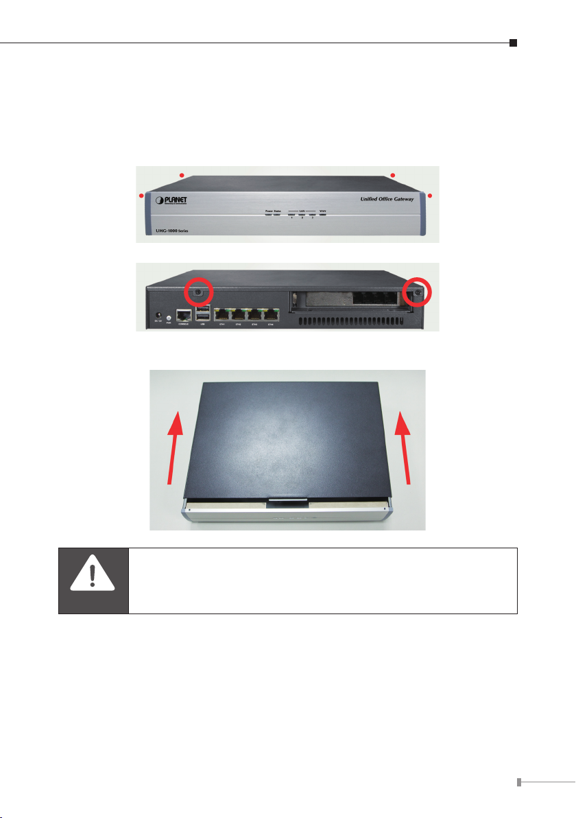
3. Hardware Installation
Caution
3.1 Removing the Chassis Cover
The screws around the cover are used to secure the cover to the chas sis. l
Remove these screws and put them in a safe place for later use.
Slide the cover backward then remove it from the chassis. l
Prior to removing the chassis cover, make sure the unit’s power is
off and disconnected from the power sources to prevent electric
shock or system damage.
3.2 The Hard Disk Installation
The 2.5” SATA HDD is necessary for system operating. Please install at least 80G
HDD before system congurations.
Remove the drive bay from the chassis. l
Page 6
6
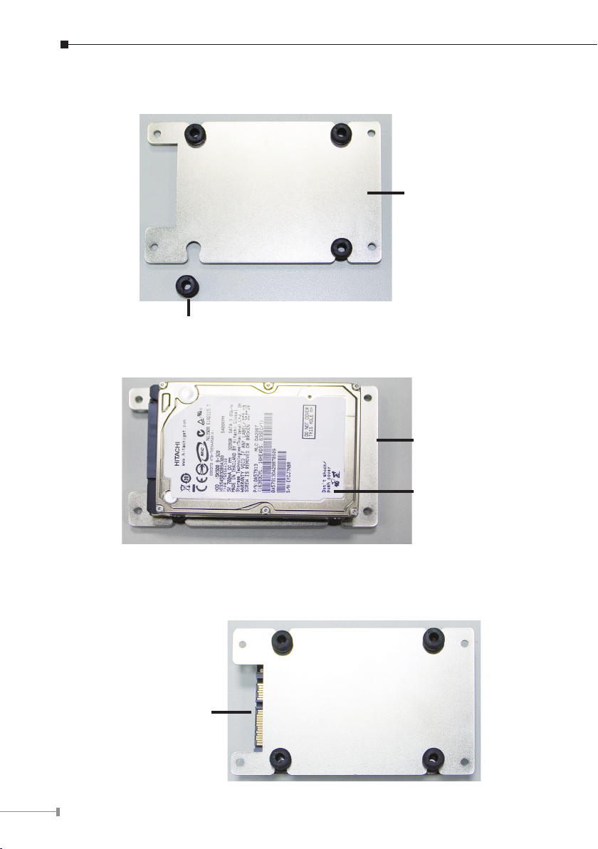
Insert the provided dampers on the sides of the drive bay. l
Drive bay
Damper
Place the SATA drive on the drive bay. l
Drive bay
SATA drive
Turn to the other side of the bay then use the provided mounting screws to l
secure the SATA drive to the drive bay.
Connector side of
the SATA drive
Page 7

7
The photo below shows the screws mounted in place. l
SATA drive located
Locate for the SATA data connector and the SATA power connector on the l
motherboard.
underneath
Mounting screw
SATA power
connector
SATA data
connector
Page 8

8
Connect the provided SATA data cable and SATA power cable to the connectors l
on the motherboard.
SATA power
cable
SATA data
cable
Locate for the mounting studs on the board. l
Mounting
stud
Page 9

9
Align the mounting holes of the drive bay with the mounting studs on the board l
then use the provided mounting screws to secure the drive bay in place.
Connect the SATA data cable and SATA power cable to the SATA drive. l
Putting the cover back to the chas sis and lock the screws. l
Page 10

10
4. Physical Connection
Internet
Internet
PC
IP Phone
IP Phone
PC
Switch
4.1 WAN Connection
Locate the WAN port on the rear panel. l
Connect the WAN port with the Ethernet cable. l
4.2 LAN Port Connection
There are 3 Ethernet ports on the rear panel. It is recommended to connect the l
third party switches to the LAN port to expand the LAN ports.
Page 11

11
4.3 PSTN FXO Port Connection
Internet
PSTN
PC
IP Phone
IP Phone
PC
Switch
Locate the voice port of the PSTN adapter on the rear panel. l
The Analog PSTN port may vary from 4 FXO ports. l
Connect one or more telephone cables to one of the selected FXO port. l
Page 12

12
5. Quick Setup Wizard
From this chapter, we will describe how to use PLANET View to congure and
control the UMG-1000 / UMG-1000W features and setup IT services conguration.
PLANET View enables you easily navigate through all IT congurations and
services.
5.1 First Time Login
Now that the network connection between your PC and UMG-1000 / UMG-1000W
has been established, you must login in order to access PLANET View.
Launch a web browser (for example: IE, Firefox etc.) and type the
UMG-1000 / UMG-1000W IP address in the address bar. The default address is
“http://192.168.1.1”.
If you can not see the following login page, recheck your physical LAN connection
and repeat Section “LAN Connection”. To avoid web-based management abused
by unauthorized users, the login sessions will logout automatically if the session is
inactive for more than 5 minutes. Type in an authorized username and password
and then click the button “Apply”. The default username is “admin”, and its
password is “admin” all in lower case.
5.2 Welcome to Quick Start
After the rst login, an easy and short quick start up should be completed to
make the UMG-1000 / UMG-1000W service normally. There is an alternative
selection in the page “Welcome”. One selection is for “Quick Start” and the
other is for “Faster Recovery UMG to UMG” which will be explained in the user’s
manual. The quick start includes ve steps which will lead administrator to setup
the UMG-1000 / UMG-1000W. Check the rst radio box and then click the button
“Start” to continue.
Page 13

13
Step 1: Create the Company Prole
This page allows an administrator to build a company prole. Specify the prole
and then click the button “Next” to go to step 2.
Item Description
Company Specify your company name.
Location Specify your city name.
Country Specify your country name.
Time Zone Specify the time zone.
PBX Extension
Specify the prex of the extensions. All PBX extensions will
be prexed with this number. (X=0~9).
Page 14

14
Step 2: Activating UMG-1000 / UMG-1000W services
The UMG-1000 / UMG-1000W allow the administrator to activate the service on
demand. By default, all services are inactive. The administrator can activate the
service in this page by checking the radio box of the corresponding service. The
activated services will start up by using the default conguration after the quick
start. Click the button “Next” to go to step 3.
Item Description
PBX Enable or disable the IP PBX service.
PPTP VPN Enable or disable the PPTP VPN service.
Email Enable or disable the Email service.
Network Storage Enable or disable the network storage service.
Internet Domain
Name
Specify a valid Internet domain for the email server if the
email service is enabled.
Step 3: Setting up the Internet Connection
This page allows the administrator to quickly setup the WAN connection. To setup
the Internet connection, you should be awarded of what method you are using
to connect to the Internet. All technical information should be provided by your
Internet Service Provider (ISP). The ISP type should be one of the followings:
static, DHCP, PPPoE or PPTP. Select your ISP type in the drop down menu. Specify
the Internet connection conguration and then click the button “Next” to go to step
4 or click the button “Skip” to skip this step.
Page 15

15
AUTO DETECT ISP TYPE
By clicking the button “Detect”, you can make the UMG-1000 / UMG-1000W to
recognize the ISP type automatically.
It may take a while to detect your ISP type. Please wait.
The ISP type will be detected and the result will be presented as follows. If
“Network Cable Disconnected” is detected, please recheck the physical connection
and repeat the action as shown in Section “WAN Connection”. There could be more
than one ISP type recognized, so choose the most suitable type from the list and
then click the button “Next” to continue.
Page 16

16
MANUAL SETUP INTERNET CONFIURATION: STATIC
If your ISP type is “Static”, choose it as your ISP type and setup the conguration.
Item Description
IP Address Specify the static IP address.
Subnet Mask Address Specify the subnet mask address.
Default Gateway Address Specify the IP address of the default gateway.
DNS Server Address
MAC Address Show MAC address information.
MANUAL SETUP INTERNET CONFIURATION: DHCP
If your ISP type is “DHCP”, choose it as your ISP type and setup the conguration.
Specify the IP address of the primary and
secondary Domain Name System.
Item Description
DNS Server
Address
MAC Address Show MAC address information.
Automatically obtain the DNS address or specify the IP
address of the primary and secondary DNS server.
Page 17

17
MANUAL SETUP INTERNET CONFIURATION: PPPOE
If your ISP type is “PPPoE”, choose it as your ISP type and setup the conguration.
Item Description
Login Name Specify the login username to the PPPoE server.
Password Specify the login password to the PPPoE server.
Conrm Password Retype the password.
Static IP Address Specify whether you have a static IP address.
IP address
Subnet Mask
Address
DNS Server
Address
MAC Address Show MAC address information.
Specify your static WAN IP address if you have enabled
the “Static IP Address”.
Specify the subnet mask address if you have enabled the
“Static IP Address”.
Automatically obtain the DNS address or specify the IP
address of the primary and secondary DNS server.
Page 18

18
MANUAL SETUP INTERNET CONFIURATION: PPTP
If your ISP type is “PPTP”, choose it as your ISP type and setup the conguration.
Item Description
PPTP Server Specify the PPTP server IP address.
Login Name Specify the username to login to the PPTP server.
Password
Conrm Password Retype the password.
Static IP Address Specify whether you have a static WAN IP address.
IP address Specify whether you have a static IP address.
Subnet Mask
Address
DNS Server
Address
MAC Address Show MAC address information
Specify the corresponding password to login to the PPTP
server.
Specify your static WAN IP address if you have enabled
the “Static IP Address”.
Specify the subnet mask address if you have enabled the
“Static IP Address”.
Page 19

19
Step 4: Creating the Network Storage
This page allows the administrator to quickly setup the storage. Because the
UMG-1000 Series just could install one hard disk, so that just the “JBOD” option
can be selected. Then click the button “Next” to go to step 5.
Step 5: Conrmation
Please recheck your input data to ensure the accurate. Click the button “Back”
to make changes. Then conrm your data and wait for the accomplishment of
the wizard. It will take a couple of minutes. Please “do not” close the browser.
The browser will show the RAID building progress. After nishing the wizard
successfully, the page of “Personal Account Web Administration” will automatically
appear.
Page 20

Further information
For further detail congurations and information can be found in the user’s manual
CD.
If you have other questions, please contact the local dealer where you purchasing
this product.
20
 Loading...