

Page 1

1
SGSW-24040 / SGSW-24040R
24-Port 10/100/1000M bps
User’s Manual of SGSW-24040 / 24240 Series
User’s Manual
Layer 2 Managed Stackable Switch
SGSW-24040P / SGSW-24040P4
24G PoE Layer2 Managed Stackable Switch
SGSW-24240 / SGSW-24240R
24-Port 100/1000 SF P Fiber
Layer2 Managed Stackable Sw itch
SGSW-24040HP
24G High PoE Layer2 Managed Stackable Switch
Page 2

User’s Manual of SGSW-24040 / 24240 Series
2
Trademarks
Copyright © PLANET Technology Corp. 2011.
Contents subject to which revision without prior notice.
PLANET is a registered trademark of PLANET Technology Corp. All other trademarks belong to their respective owners.
Disclaimer
PLANET Technology does not warrant that the hardware will work properly in all environments and applications, and makes no
warranty and representation, either implied or expressed, with respect to the quality, performance, merchantability, or fitness for
a particular purpose. PLANET has made every effort to ensure that this User's Manual is accurate; PLANET disclaims liability
for any inaccuracies or omissions that may have occurred.
Information in this User's Manual is subject to change without notice and does not represent a commitment on the part of
PLANET. PLANET assumes no responsib ility for any inaccuracies that may be contained in this User's Manual. PLANET makes
no commitment to updat e or k eep curr en t t h e in form ation in this User's Manual , an d re serv es th e r i ght to make improvements t o
this User's Manual and/or to the products described in this User's Manual, at any time without notice.
If you find information in this manual that is incorrect, misleading, or incomplete, we would appreciate your comments and
suggestions.
FCC Warning
This equipment has been tested and found to comply with the limits for a Class A digital device, pursuant to Part 15 of the FCC
Rules. These limits are designed to provide reasonable protection against harmful interference when the equipment is operated
in a commercial environment. This equipment generates, uses, and can radiate radio frequency energy and, if not installed and
used in accordance with the Instruction manual, may cause harmful interference to radio communications. Operation of this
equipment in a residential area is likely to cause harmful interference in which case the user will be required to correct the
interference at whose own expense.
CE Mark Warning
This is a Class A product. In a domestic environment, this product may cause radio interference, in which case the user may be
required to take adequate measures.
Energy Saving Note of the Device
This power required device does not support Standby mode operation.
For energy saving, please remove the power cable to disconnect the device from the power circuit.
Without removing power cable, the device will still consuming power from the power source. In the view of Saving the Energy
and reduce the unnecessary power consuming, it is strongly suggested to remove the power connection for the device if this
device is not intended to be active.
WEEE Warning
To avoid the potential effects on the environment and human health as a result of the presence of
hazardous substances in electrical and electronic equipment, end users of electrical and electronic
equipment should understand the meaning of the crossed-out wheeled bin symbol. Do not dispose of
WEEE as unsorted municipal w aste and have to colle ct such WEEE separately.
Revision
PLANET 24-Port 10/100/1000Mbps with 4 Shared SFP / 24 100/1000 SFP Slots with 8 Shared TP Managed Stackable Switch
User's Manual
FOR MODELS: SGSW-24040 / SGSW-24240 Series
REVISION: 1.6 (February.2011)
Part No: EM-SGSW-24040_24240 Series (2080-A93070-004)
Page 3

User’s Manual of SGSW-24040 / 24240 Series
3
TABLE OF CONETNTS
1. INTRODUTION .................................................................................................................... 19
1.1 Packet Contents ......................................................................................................................................... 19
1.2 Product Description ................................................................................................................................... 19
1.3 How to Use This Manual ............................................................................................................................ 22
1.4 Product Features ........................................................................................................................................ 23
1.5 Product Specificatio n ................................................................................................................................ 26
2. INSTALLATION ................................................................................................................... 34
2.1 Hardware Description ................................................................................................................................ 34
2.1.1 Switch Front Panel .............................................................................................................................................. 34
2.1.2 LED Indications ................................................................................................................................................... 36
2.1.3 Switch Rear Panel ............................................................................................................................................... 40
2.2 Install the Switch ........................................................................................................................................ 43
2.2.1 Desktop Installati on ............................................................................................................................................. 43
2.2.2 Rack Mounting ..................................................................................................................................................... 44
2.2.3 Installing the SFP transceiver .............................................................................................................................. 45
2.2.4 Connecting DC Power Supply ............................................................................................................................. 47
2.3 Stack Installation ........................................................................................................................................ 49
2.3.1 Connecting Stacking cable .................................................................................................................................. 50
2.3.2 Management Stacking ......................................................................................................................................... 50
3. SWITCH MANAGEMENT .................................................................................................... 53
3.1 Requirements .............................................................................................................................................. 53
3.2 Management Access Overview ................................................................................................................. 54
3.3 Administrati on Console ............................................................................................................................. 54
3.4 Web Management ....................................................................................................................................... 56
3.5 SNMP-Based Network Management ......................................................................................................... 57
4. WEB CONFIGURATION ...................................................................................................... 58
4.1 Main Web Page ........................................................................................................................................... 61
4.2 System ......................................................................................................................................................... 63
Page 4

User’s Manual of SGSW-24040 / 24240 Series
4
4.2.1 System Information .............................................................................................................................................. 64
4.2.2 IP Configuration ................................................................................................................................................... 65
4.2.3 IPv6 Configuration ............................................................................................................................................... 66
4.2.4 Users Configuration ............................................................................................................................................. 67
4.2.5 Users Privilege Levels ......................................................................................................................................... 70
4.2.6 NTP Configuration ............................................................................................................................................... 72
4.2.7 UPnP Configuration ............................................................................................................................................. 73
4.2.8 DHCP Relay ........................................................................................................................................................ 74
4.2.9 DHCP Relay Statistics ......................................................................................................................................... 76
4.2.10 CPU Load .......................................................................................................................................................... 78
4.2.1 1 Sy st em Log ........................................................................................................................................................ 79
4.2.12 Detailed Log ...................................................................................................................................................... 80
4.2.13 Remote Syslog .................................................................................................................................................. 81
4.2.14 SMTP Configure ................................................................................................................................................ 81
4.2.15 Web Firmware Upgrade ..................................................................................................................................... 83
4.2.16 TFTP Firmware Upgrade ................................................................................................................................... 84
4.2.17 Configuration Backup ........................................................................................................................................ 85
4.2.18 Configuration Upload ......................................................................................................................................... 87
4.2.19 Factory Default .................................................................................................................................................. 88
4.2.20 System Reboot .................................................................................................................................................. 89
4.3 Simple Network Management Protocol .................................................................................................... 90
4.3.1 SNMP Overview .................................................................................................................................................. 90
4.3.2 SNMP System Configuration ............................................................................................................................... 91
4.3.3 SNMP System Information Configuration ............................................................................................................ 92
4.3.4 SNMP Trap Configuration .................................................................................................................................... 93
4.3.5 SNMPv3 Configuration ........................................................................................................................................ 95
4.3.5.1 SNMPv3 Communities Configuration ........................................................................................................ 95
4.3.5.2 SNMPv3 Users Configuration .................................................................................................................... 95
4.3.5.3 SNMPv3 Groups Configuration ................................................................................................................. 98
4.3.5.4 SNMPv3 Views Configuration .................................................................................................................... 99
4.3.5.5 SNMPv3 Accesses Configuration ............................................................................................................ 100
4.4 Port Management ..................................................................................................................................... 102
4.4.1 Port Configuration .............................................................................................................................................. 102
4.4.2 Port Statistics Overview ..................................................................................................................................... 104
4.4.3 Port Statistics Detail ........................................................................................................................................... 105
4.4.4 SFP Module Information .................................................................................................................................... 107
4.4.5 Port Mirroring Configuration ............................................................................................................................... 108
4.5 Link Aggregation ...................................................................................................................................... 112
4.5.1 Static Aggregation Configuration ....................................................................................................................... 114
Page 5

User’s Manual of SGSW-24040 / 24240 Series
5
4.5.2 LACP Configuration ........................................................................................................................................... 116
4.5.3 LACP System Status ......................................................................................................................................... 117
4.5.4 LACP Port Status ............................................................................................................................................... 118
4.5.5 LACP Port Statistics ........................................................................................................................................... 119
4.6 VLAN .......................................................................................................................................................... 121
4.6.1 VLAN Overview ................................................................................................................................................. 121
4.6.2 IEEE 802.1Q VLAN ........................................................................................................................................... 121
4.6.3 VLAN Basic Information..................................................................................................................................... 125
4.6.4 VLAN Port Configuration ................................................................................................................................... 126
4.6.5 VLAN Membership Configuration ...................................................................................................................... 130
4.6.6 VLAN Membership Status for User Static .......................................................................................................... 131
4.6.7 VLAN Port Status for User Static ....................................................................................................................... 132
4.6.8 Port Isolation Configuration ............................................................................................................................... 134
4.6.9 Private VLAN Membership Configuration .......................................................................................................... 137
4.6.10 VLAN setting example: .................................................................................................................................... 139
4.6.10.1 Two separate 802.1Q VLAN .................................................................................................................. 139
4.6.10.2 VLAN Trunking between two 802.1Q aware switch ............................................................................... 143
4.6.10.4 Port Isolate ............................................................................................................................................ 144
4.7 Spanning Tree Protocol ........................................................................................................................... 147
4.7.1 Theory ............................................................................................................................................................... 147
4.7.2 STP Bridge Configuration .................................................................................................................................. 153
4.7.3 Bridge Status ..................................................................................................................................................... 155
4.7.4 CIST Port Configuration ..................................................................................................................................... 156
4.7.5 MSTI Priorities ................................................................................................................................................... 159
4.7.6 MSTI Configuration ............................................................................................................................................ 160
4.7.7 MSTI Ports Configuration .................................................................................................................................. 161
4.7.8 Port Status ......................................................................................................................................................... 164
4.7.9 Port Statistics ..................................................................................................................................................... 165
4.8 Multicast .................................................................................................................................................... 167
4.8.1 IGMP Snooping ................................................................................................................................................. 167
4.8.2 IGMP Snooping Configuration ........................................................................................................................... 171
4.8.3 IGMP Port Related Configuration ...................................................................................................................... 172
4.8.4 VLAN Configuration ........................................................................................................................................... 173
4.8.5 Port Group Filtering ........................................................................................................................................... 174
4.8.6 IGMP Snooping Status ...................................................................................................................................... 175
4.8.7 MVR Configuration ............................................................................................................................................ 176
4.8.8 MVR Status ........................................................................................................................................................ 178
4.9 Quality of Service ..................................................................................................................................... 180
Page 6

User’s Manual of SGSW-24040 / 24240 Series
6
4.9.1 Understand QOS ............................................................................................................................................... 180
4.9.2 QCL Configuration Wizard ................................................................................................................................. 181
4.9.2.1 Set up Policy Rules ................................................................................................................................. 182
4.9.2.2 Set up Typical Network Application Rules ............................................................................................... 183
4.9.2.3 Set up ToS Precedence Mapping ............................................................................................................ 185
4.9.2.4 Set up VLAN Tag Priority Mapping .......................................................................................................... 187
4.9.3 QoS Control List Configuration .......................................................................................................................... 188
4.9.3.1 QoS Control Entry Configuration ............................................................................................................. 189
4.9.4 Port QoS Configuration...................................................................................................................................... 190
4.9.5 Bandwidth Control ............................................................................................................................................. 192
4.9.6 Storm Control Configuration .............................................................................................................................. 194
4.9.7 QoS Statistics .................................................................................................................................................... 195
4.9.8 DSCP Remarking .............................................................................................................................................. 196
4.9.9 Voice VLAN Configuration ................................................................................................................................. 198
4.9.10 Voice VLAN OUI Table ..................................................................................................................................... 201
4.10 Access Control Lists .............................................................................................................................. 202
4.10.1 Access Control List Status ............................................................................................................................... 202
4.10.2 Access Control List Configuration .................................................................................................................... 203
4.10.3 ACE Configuration ........................................................................................................................................... 205
4.10.4 ACL Ports Configuration .................................................................................................................................. 213
4.10.5 ACL Rate Limiter Configuration ....................................................................................................................... 215
4.11 Authentication ......................................................................................................................................... 217
4.11.1 Understanding IEEE 802.1X Port-Based Authent ication .................................................................................. 218
4.1 1.2 Authenti cation Configuration ............................................................................................................................ 221
4.11.3 Network Access Server Configuration .............................................................................................................. 222
4.11.4 Network Access Overview ............................................................................................................................... 233
4.11.5 Network Access Statistics ................................................................................................................................ 234
4.11.6 Authentication Server Configuration................................................................................................................. 240
4.11.7 RADIUS Overview ........................................................................................................................................... 244
4.11.8 RADIUS Details ............................................................................................................................................... 245
4.11.9 Windows Platform RADIUS Server Configuration ............................................................................................ 251
4.11.10 802.1X Client Configuration ........................................................................................................................... 256
4.12 Security ................................................................................................................................................... 259
4.12.1 Port Limit Control ............................................................................................................................................. 259
4.12.2 Access Management ....................................................................................................................................... 263
4.12.3 Access Management Statistics ........................................................................................................................ 264
4.12.4 HTTPs ............................................................................................................................................................. 265
4.12.5 SSH ................................................................................................................................................................. 265
4.12.6 Port Security Status ......................................................................................................................................... 266
Page 7

User’s Manual of SGSW-24040 / 24240 Series
7
4.12.7 Port Security Detail .......................................................................................................................................... 269
4.12.8 DHCP Snooping .............................................................................................................................................. 270
4.12.9 DHCP Snooping Statistics ............................................................................................................................... 271
4.12.10 IP Source Guard Configuration ...................................................................................................................... 272
4.12.11 IP Source Guard Static Table ......................................................................................................................... 274
4.12.12 ARP Inspection .............................................................................................................................................. 275
4.12.13 ARP Inspection Stati c T able ........................................................................................................................... 277
4.13 Address Table ......................................................................................................................................... 279
4.13.1 MAC Address Table Configuration ................................................................................................................... 279
4.13.2 Static MAC Table Configuration ....................................................................................................................... 280
4.13.3 MAC Address Table Status .............................................................................................................................. 280
4.13.4 MAC Table Learning ........................................................................................................................................ 282
4.13.5 Dynamic AR P I ns pec tio n Table ........................................................................................................................ 283
4.13.6 Dynamic IP Source Guard Table ...................................................................................................................... 285
4.14 LLDP ........................................................................................................................................................ 287
4.14.1 Link Layer Discovery Protocol ......................................................................................................................... 287
4.14.2 LLDP Configuration ......................................................................................................................................... 287
4.14.3 LLDPMED Configuration ................................................................................................................................. 291
4.14.4 LLDP-MED Neighbor ....................................................................................................................................... 297
4.14.5 Neighbor .......................................................................................................................................................... 300
4.14.6 Port Statistics ................................................................................................................................................... 301
4.15 Network Diagnostics .............................................................................................................................. 304
4.15.1 Ping ................................................................................................................................................................. 304
4.15.2 IPv6 Ping ......................................................................................................................................................... 305
4.15.3 Remote IP Ping Test ........................................................................................................................................ 306
4.15.4 Cable Diagnostics ............................................................................................................................................ 308
4.16 Power over Ethernet (SGSW-24040P / SGSW-24040P4 / SGSW-24040HP) ...................................... 310
4.16.1 Power over Ethernet Powered Device ............................................................................................................. 310
4.16.2 Power Configuration ........................................................................................................................................ 311
4.16.3 Port Configuration ............................................................................................................................................ 314
4.16.4 PoE Status ....................................................................................................................................................... 316
4.16.5 PoE Schedule .................................................................................................................................................. 318
4.16.6 LLDP Neighbor Power Over Ethernet .............................................................................................................. 319
4.17 Stack ........................................................................................................................................................ 321
4.17.1 Stack ................................................................................................................................................................ 322
4.17.1.1 Switch IDs ........................................................................................................................................... 322
4.17.1.2 Master Election ................................................................................................................................... 323
4.17.1.3 Stack Redundancy .............................................................................................................................. 324
Page 8

User’s Manual of SGSW-24040 / 24240 Series
8
4.17.1.4 Shortest Path Forwarding ................................................................................................................... 324
4.17.2 Stack Configuration.......................................................................................................................................... 325
4.17.3 Stack Information ............................................................................................................................................. 328
4.17.4 Stack Port State Ovewview .............................................................................................................................. 329
4.17.5 Stack Example ................................................................................................................................................. 330
5. COMMAND LINE INTERFACE .......................................................................................... 334
5.1 Accessing the CLI .................................................................................................................................... 334
Logon to the Console .......................................................................................................................................... 334
Configure IP address ........................................................................................................................................... 334
5.2 Telnet Login .............................................................................................................................................. 337
6. Command Line Mode ....................................................................................................... 338
6.1 System Command .................................................................................................................................... 338
System Configuration .......................................................................................................................................... 338
System Name ...................................................................................................................................................... 339
System Contact ................................................................................................................................................... 340
System Location .................................................................................................................................................. 340
System Tim ez one ................................................................................................................................................ 341
System Prompt .................................................................................................................................................... 341
System Reboot .................................................................................................................................................... 342
System Restore Default....................................................................................................................................... 342
System Load ....................................................................................................................................................... 343
System Log ......................................................................................................................................................... 343
6.2 Stack .......................................................................................................................................................... 345
Stack Lis t ............................................................................................................................................................. 345
Stack Master Priority............................................................................................................................................ 345
Stack Master Reelect........................................................................................................................................... 346
Stack Select ......................................................................................................................................................... 346
Stack SID Swap ................................................................................................................................................... 346
Stack SID Delete ................................................................................................................................................. 347
St ack SID Assign ................................................................................................................................................. 347
6.3 IP Command .............................................................................................................................................. 349
IP Configuration ................................................................................................................................................... 349
IP DHCP .............................................................................................................................................................. 349
IP Setup ............................................................................................................................................................... 350
IP Ping ................................................................................................................................................................. 351
IP DNS ................................................................................................................................................................ 351
Page 9

User’s Manual of SGSW-24040 / 24240 Series
9
IP DNS Proxy ...................................................................................................................................................... 352
IPv6 AUTOCINFIG .............................................................................................................................................. 352
IPv6 Setup ........................................................................................................................................................... 353
IPv6 Ping ............................................................................................................................................................. 354
IP NTP Configuration ........................................................................................................................................... 354
IP NTP Mode ....................................................................................................................................................... 355
IP NTP Server Add .............................................................................................................................................. 355
IP NTP Server IPv6 Add ...................................................................................................................................... 356
IP NTP Server Delete .......................................................................................................................................... 356
6.4 Port Management Command ................................................................................................................... 358
Port Configuration ............................................................................................................................................... 358
Port Mode ............................................................................................................................................................ 358
Port Flow Control ................................................................................................................................................. 359
Port State ............................................................................................................................................................. 360
Port Maximum Frame .......................................................................................................................................... 360
Port Power ........................................................................................................................................................... 361
Port SFP .............................................................................................................................................................. 361
Port Excessive ..................................................................................................................................................... 362
Port Statistics ....................................................................................................................................................... 362
Port VeriPHY ....................................................................................................................................................... 363
6.5 MAC Address Table Command ............................................................................................................... 364
MAC Configuration .............................................................................................................................................. 364
MAC Add ............................................................................................................................................................. 365
MAC Delete ......................................................................................................................................................... 365
MAC Lookup ........................................................................................................................................................ 366
MAC Age Time .................................................................................................................................................... 366
MAC Learning ..................................................................................................................................................... 367
MAC Dump .......................................................................................................................................................... 367
MAC Statistics ..................................................................................................................................................... 368
MAC Flush ........................................................................................................................................................... 369
6.6 VLAN Configuration Command .............................................................................................................. 370
VLAN Configuration ............................................................................................................................................. 370
VLAV PVID .......................................................................................................................................................... 370
VLAN Frame T y pe ............................................................................................................................................... 371
VLAN Ingress Filter ............................................................................................................................................. 371
VLAN Mode ......................................................................................................................................................... 372
VLAN Link T y pe ................................................................................................................................................... 373
VLAN Q-in-Q Mode ............................................................................................................................................. 373
VLAN Ethernet Type ............................................................................................................................................ 374
Page 10

User’s Manual of SGSW-24040 / 24240 Series
10
VLAN Add ............................................................................................................................................................ 374
VLAN Delete ........................................................................................................................................................ 375
VLAN Lookup ...................................................................................................................................................... 375
VLAN Status ........................................................................................................................................................ 376
6.7 Private VLAN Configuration Command ................................................................................................. 378
PVLAN Configuration .......................................................................................................................................... 378
PVLAN Add ......................................................................................................................................................... 379
PVLAN Delete ..................................................................................................................................................... 379
PVLAN Lookup .................................................................................................................................................... 380
PVLAN Isolate ..................................................................................................................................................... 380
6.8 Security Command ................................................................................................................................... 382
Security Switch User Configuration ..................................................................................................................... 382
Security Switch User Add .................................................................................................................................... 382
Security Switch User Delete ................................................................................................................................ 383
Security Switch Privilege Level Configuration ..................................................................................................... 383
Security Switch Privilege Level Group ................................................................................................................. 384
Security Switch Privilege Level Current ............................................................................................................... 385
Security Switch Auth Configuration ..................................................................................................................... 385
Security Switch Auth Method ............................................................................................................................... 386
Security Switch SSH Configuration ..................................................................................................................... 387
Security Switch SSH Mode .................................................................................................................................. 387
Security Switch HTTPs Configuration ................................................................................................................. 388
Security Switch HTTPs Mode .............................................................................................................................. 388
Security Switch HTTPs Redirect ......................................................................................................................... 389
Security Switch Access Configuration ................................................................................................................. 389
Security Switch Access Mode .............................................................................................................................. 390
Security Switch Access Add ................................................................................................................................ 390
Security Switch Access IPv6 Add ........................................................................................................................ 391
Security Switch Access Delete ............................................................................................................................ 392
Security Switch Access Lookup ........................................................................................................................... 392
Security Switch Access Clear .............................................................................................................................. 392
Security Switch Access Statistics ........................................................................................................................ 393
Security Switch SNMP Configuration .................................................................................................................. 393
Security Switch SNMP Mode ............................................................................................................................... 395
Security Switch SNMP Version ............................................................................................................................ 396
Security Switch SNMP Read Community ............................................................................................................ 396
Security Switch SNMP Write Community ............................................................................................................ 397
Security Switch SNMP Trap Mode....................................................................................................................... 397
Security Switch SNMP Trap Version.................................................................................................................... 398
Page 11

User’s Manual of SGSW-24040 / 24240 Series
11
Security Switch SNMP Trap Community ............................................................................................................. 398
Security Switch SNMP Trap Destination .............................................................................................................. 399
Security Switch SNMP Trap IPv6 Destination ..................................................................................................... 399
Security Switch SNMP Trap Authentication Failure ............................................................................................. 400
Security Switch SNMP Trap Link-up .................................................................................................................... 400
Security Switch SNMP Trap Inform Mode ........................................................................................................... 401
Security Switch SNMP Trap Inform Timeout ........................................................................................................ 402
Security Switch SNMP Trap Inform Retry Times ................................................................................................. 402
Security Switch SNMP Trap Probe Security Engine ID ....................................................................................... 403
Security Switch SNMP Trap Security Engine ID .................................................................................................. 403
Security Switch SNMP Trap Security Name ........................................................................................................ 404
Security Switch SNMP Engine ID ........................................................................................................................ 404
Security Switch SNMP Community Add .............................................................................................................. 404
Security Switch SNMP Community Delete .......................................................................................................... 405
Security Switch SNMP Community Lookup ......................................................................................................... 405
Security Switch SNMP User Add ......................................................................................................................... 406
Security Switch SNMP User Delete ..................................................................................................................... 407
Security Switch SNMP User Changekey ............................................................................................................. 407
Security Switch SNMP User Lookup ................................................................................................................... 407
Security Switch SNMP Group Add....................................................................................................................... 408
Security Switch SNMP Group Delete .................................................................................................................. 409
Security Switch SNMP Group Lookup ................................................................................................................. 409
Security Switch SNMP View Add ......................................................................................................................... 410
Security Switch SNMP View Delete ..................................................................................................................... 410
Security Switch SNMP View Lookup ................................................................................................................... 410
Security Switch SNMP Access Add ..................................................................................................................... 411
Security Switch SNMP Access Delete ................................................................................................................. 412
Security Switch SNMP Access Lookup ................................................................................................................ 412
Security Network Psec Switch ............................................................................................................................. 413
Security Network Psec Port ................................................................................................................................. 414
Security Network Limit Configuration .................................................................................................................. 415
Security Network Limit Mode ............................................................................................................................... 416
Security Network Limit Aging ............................................................................................................................... 416
Security Network Limit Agetime ........................................................................................................................... 417
Security Network Limit Port ................................................................................................................................. 417
Security Network Limit Limit ................................................................................................................................ 418
Security Network Limit Action .............................................................................................................................. 419
Security Network Limit Reopen ........................................................................................................................... 419
Security Network NAS Configuration ................................................................................................................... 420
Security Network NAS Mode ............................................................................................................................... 420
Page 12

User’s Manual of SGSW-24040 / 24240 Series
12
Security Network NAS State ................................................................................................................................ 421
Security Network NAS Reauthentication ............................................................................................................. 422
Security Network NAS ReauthPeriod .................................................................................................................. 422
Security Network NAS EapolTimeout .................................................................................................................. 423
Security Network NAS Agetime ........................................................................................................................... 423
Security Network NAS Holdtime .......................................................................................................................... 424
Security Network NAS RADIUS_QoS ................................................................................................................. 424
Security Network NAS RADIUS_VLAN ............................................................................................................... 425
Security Network NAS Guest_VLAN ................................................................................................................... 425
Security Network NAS Authenticate .................................................................................................................... 426
Security Network NAS Statistics .......................................................................................................................... 427
Security Network ACL Configuration ................................................................................................................... 428
Security Network ACL Action ............................................................................................................................... 429
Security Network ACL Policy ............................................................................................................................... 430
Security Network ACL Rate ................................................................................................................................. 431
Security Network ACL Add .................................................................................................................................. 431
Security Network ACL Delete .............................................................................................................................. 433
Security Network ACL Lookup ............................................................................................................................. 433
Security Network ACL Clear ................................................................................................................................ 433
Security Network ACL Status ............................................................................................................................... 434
Security Network DHCP Relay Configuration ...................................................................................................... 434
Security Network DHCP Relay Mode .................................................................................................................. 435
Security Network DHCP Relay Server ................................................................................................................. 435
Security Network DHCP Relay Information Mode ............................................................................................... 436
Security Network DHCP Relay Information Policy ............................................................................................... 437
Security Network DHCP Relay Statistics ............................................................................................................. 437
Security Network DHCP Snooping Configuration ................................................................................................ 438
Security Network DHCP Snooping Mode ............................................................................................................ 439
Security Network DHCP Snooping Port Mode ..................................................................................................... 439
Security Network DHCP Snooping Statistics ....................................................................................................... 440
Security Network IP Source Guard Configuration ............................................................................................... 441
Security Network IP Source Guard Mode ............................................................................................................ 442
Security Network IP Source Guard Port Mode .................................................................................................... 442
Security Network IP Source Guard Limit ............................................................................................................. 443
Security Network IP Source Guard Entry ............................................................................................................ 444
Security Network IP Source Guard Status ........................................................................................................... 444
Security Network ARP Inspection Configuration .................................................................................................. 445
Security Network ARP Inspection Mode .............................................................................................................. 445
Security Network ARP Inspection Port Mode ...................................................................................................... 445
Security Network ARP Inspection Entry ............................................................................................................... 446
Page 13

User’s Manual of SGSW-24040 / 24240 Series
13
Security Network ARP Inspection Status ............................................................................................................. 447
Security AAA Configuration ................................................................................................................................. 447
Security AAA Timeout .......................................................................................................................................... 448
Security AAA Deadtime ....................................................................................................................................... 449
Security AAA RADIUS ......................................................................................................................................... 449
Security AAA ACCT_RADIUS .............................................................................................................................. 450
Security AAA T ACACS+ ...................................................................................................................................... 451
Security AAA Statistics......................................................................................................................................... 451
6.9 Spanning Tree Protocol Command ........................................................................................................ 453
STP Configuration ............................................................................................................................................... 453
STP Version ........................................................................................................................................................ 453
STP Tx Hold ........................................................................................................................................................ 454
STP MaxH ops ..................................................................................................................................................... 454
STP MaxAge ....................................................................................................................................................... 455
STP FwdDelay .................................................................................................................................................... 455
STP CName ........................................................................................................................................................ 456
STP BPDU Filter.................................................................................................................................................. 456
STP BPDU Guard................................................................................................................................................ 457
STP Recovery ..................................................................................................................................................... 457
STP Status .......................................................................................................................................................... 458
STP MSTI Priority ................................................................................................................................................ 459
STP MST I Ma p .................................................................................................................................................... 459
STP MSTI Add ..................................................................................................................................................... 460
STP Port Configuration ........................................................................................................................................ 460
STP Port Mode .................................................................................................................................................... 461
STP Port Edge .................................................................................................................................................... 461
STP Port AutoEdge ............................................................................................................................................. 462
STP Port P2P ...................................................................................................................................................... 462
STP Port RestrictedRole ..................................................................................................................................... 463
STP Port RestrictedTcn ....................................................................................................................................... 463
STP Port bpduGuard ........................................................................................................................................... 464
STP Port Statistic................................................................................................................................................. 464
STP Port Mcheck................................................................................................................................................. 465
STP MSTI Port Configuration .............................................................................................................................. 465
STP MSTI Port Cost ............................................................................................................................................ 466
STP MSTI Port Priority ........................................................................................................................................ 467
6.10 Multicast Configuration Comma n d ...................................................................................................... 468
IGMP Configuration ............................................................................................................................................. 468
IGMP Mo d e ......................................................................................................................................................... 468
Page 14

User’s Manual of SGSW-24040 / 24240 Series
14
IGMP Leave Proxy .............................................................................................................................................. 469
IGMP State .......................................................................................................................................................... 469
IGMP Querier ...................................................................................................................................................... 470
IGMP Fastleave ................................................................................................................................................... 470
IGMP Throttling ................................................................................................................................................... 471
IGMP Filtering ..................................................................................................................................................... 471
IGMP Router ....................................................................................................................................................... 472
IGMP Flooding .................................................................................................................................................... 473
IGMP Groups....................................................................................................................................................... 473
IGMP Status ........................................................................................................................................................ 473
6.11 Link Aggregation Command ................................................................................................................. 475
Aggregation Configuration ................................................................................................................................... 475
Aggregation Add .................................................................................................................................................. 475
Aggregation Delete .............................................................................................................................................. 476
Aggregation Lookup ............................................................................................................................................ 476
Aggregation Mode ............................................................................................................................................... 477
6.12 Link Aggregation Control Protocol Command .................................................................................... 478
LACP Configuration ............................................................................................................................................. 478
LACP Mode ......................................................................................................................................................... 479
LACP Key ............................................................................................................................................................ 479
LACP Role ........................................................................................................................................................... 480
LACP Status ........................................................................................................................................................ 480
LACP Statistics .................................................................................................................................................... 481
6.13 LLDP Command...................................................................................................................................... 482
LLDP Configuration ............................................................................................................................................. 482
LLDP Mode ......................................................................................................................................................... 482
LLDP Optional TLV .............................................................................................................................................. 483
LLDP Interval ....................................................................................................................................................... 484
LLDP Hold ........................................................................................................................................................... 484
LLDP Delay ......................................................................................................................................................... 485
LLDP Reinit ......................................................................................................................................................... 485
LLDP Statistics .................................................................................................................................................... 486
LLDP Info ............................................................................................................................................................ 487
LLDP CDP Aware ................................................................................................................................................ 487
6.14 LLDPMED Command ............................................................................................................................. 488
LLDPMED Configuration ..................................................................................................................................... 488
LLDPMED Civic ................................................................................................................................................... 488
LLDPMED ECS ................................................................................................................................................... 489
Page 15

User’s Manual of SGSW-24040 / 24240 Series
15
LLDPMED Policy Delete...................................................................................................................................... 490
LLDPMED Policy Add .......................................................................................................................................... 490
LLDPMED Port Policy ......................................................................................................................................... 491
LLDPMED Coordinates ....................................................................................................................................... 492
LLDPMED Datum ................................................................................................................................................ 492
LLDPMED Fast ................................................................................................................................................... 493
LLDPMED Info .................................................................................................................................................... 493
LLDPMED Debuge_med_transmit_var ............................................................................................................... 493
6.15 Power over Ethernet Command ............................................................................................................ 494
PoE Configuration ............................................................................................................................................... 494
PoE Mode ............................................................................................................................................................ 495
PoE Priority ......................................................................................................................................................... 495
PoE Mamagement Mode ..................................................................................................................................... 496
PoE Maximum Power .......................................................................................................................................... 497
PoE Allocated Power ........................................................................................................................................... 497
PoE Power Supply .............................................................................................................................................. 498
PoE Status ........................................................................................................................................................... 498
6.16 Quality of Service Command ................................................................................................................ 499
QoS Configuration ............................................................................................................................................... 499
QoS Classes ....................................................................................................................................................... 499
QoS Default ......................................................................................................................................................... 500
QoS Tag Priority .................................................................................................................................................. 500
QoS QCL Port ..................................................................................................................................................... 501
QoS QCL Add ...................................................................................................................................................... 501
QoS QCL Delete .................................................................................................................................................. 502
QoS QCL Lookup ................................................................................................................................................ 503
QoS Mode ........................................................................................................................................................... 503
QoS Weight ......................................................................................................................................................... 503
QoS Rate Limiter ................................................................................................................................................. 504
QoS Shaper ......................................................................................................................................................... 504
QoS Storm Unicast .............................................................................................................................................. 505
QoS Strom Multicast ............................................................................................................................................ 505
QoS Strom Broadcast .......................................................................................................................................... 506
QoS DSCP Remarking ........................................................................................................................................ 507
QoS DSCP Queue Mapping ................................................................................................................................ 507
6.17 Mirror Command .................................................................................................................................... 508
Mirror Configuration ............................................................................................................................................. 508
Mirror Port ........................................................................................................................................................... 508
Mirror SID ............................................................................................................................................................ 509
Page 16

User’s Manual of SGSW-24040 / 24240 Series
16
Mirror Mode ......................................................................................................................................................... 509
6.18 Configuration Command ....................................................................................................................... 511
Configuration Save .............................................................................................................................................. 511
Configuration Load .............................................................................................................................................. 511
6.19 Firmware Command ............................................................................................................................... 512
Firmware Load .................................................................................................................................................... 512
Firmware IPv6 Load ............................................................................................................................................ 512
6.20 UPnP Command ..................................................................................................................................... 513
UPnP Configuration ............................................................................................................................................. 513
UPnP Mode ......................................................................................................................................................... 513
UPnP TTL ............................................................................................................................................................ 514
UPnP Advertising Duration .................................................................................................................................. 514
6.21 MVR Command ....................................................................................................................................... 515
MVR Configuration .............................................................................................................................................. 515
MVR Group ......................................................................................................................................................... 516
MVR Status ......................................................................................................................................................... 516
MVR Mode .......................................................................................................................................................... 516
MVR Port Mode ................................................................................................................................................... 517
MVR Multicast VLAN ........................................................................................................................................... 517
MVR Port Type .................................................................................................................................................... 518
MVR Immediate Leave ........................................................................................................................................ 518
6.22 Voice VLAN Command ........................................................................................................................... 520
Voice VLAN Configuration ................................................................................................................................... 520
Voice VLAN Mode ............................................................................................................................................... 521
Voice VLAN ID ..................................................................................................................................................... 522
Voice VLAN Agetime ........................................................................................................................................... 522
Voice VLAN Traffic Class ..................................................................................................................................... 523
Voice VLAN OUI Add ........................................................................................................................................... 523
Voice VLAN OUI Delete....................................................................................................................................... 524
Voice VLAN OUI Clear ........................................................................................................................................ 524
Voice VLAN OUI Lookup ..................................................................................................................................... 525
Voice VLAN Port Mode ........................................................................................................................................ 525
Voice VLAN Security ........................................................................................................................................... 526
6.23 SMTP Command ..................................................................................................................................... 527
SMTP Configuration ............................................................................................................................................ 527
SMTP Mode ........................................................................................................................................................ 527
SMTP Server ....................................................................................................................................................... 527
Page 17

User’s Manual of SGSW-24040 / 24240 Series
17
SMTP Auth .......................................................................................................................................................... 528
SMTP Auth_user ................................................................................................................................................. 528
SMTP Auth_pas s ................................................................................................................................................. 529
SMTP Mailfrom .................................................................................................................................................... 529
SMTP Mailsubject................................................................................................................................................ 529
SMTP Mailto1 ...................................................................................................................................................... 530
SMTP Mailto2 ...................................................................................................................................................... 530
6.24 Show Command ..................................................................................................................................... 531
Show ACL Configuration ..................................................................................................................................... 531
Show Link Aggregation Configuration ................................................................................................................. 531
Show IGMP Configuration ................................................................................................................................... 531
Show IP Configuration ......................................................................................................................................... 531
Show LACP Configuration ................................................................................................................................... 532
Show LLDP Configuration ................................................................................................................................... 532
Show MAC Configuration .................................................................................................................................... 532
Show Mirror Configuration ................................................................................................................................... 532
Show PoE Configuration ..................................................................................................................................... 532
Show Port Configuration...................................................................................................................................... 533
Show Private VLAN Configuration ....................................................................................................................... 533
Show QoS Configuration ..................................................................................................................................... 533
Show SNMP Configuration .................................................................................................................................. 533
Show Stack Configuration ................................................................................................................................... 534
Show System Configuration ................................................................................................................................ 534
Show VLAN Configuration ................................................................................................................................... 534
Show STP Configuration ..................................................................................................................................... 534
7. SWITCH OPERATION ....................................................................................................... 535
7.1 Address Table ........................................................................................................................................... 535
7.2 Learning .................................................................................................................................................... 535
7.3 Forwarding & Filtering ............................................................................................................................. 535
7.4 Store-and-Forward ................................................................................................................................... 535
7.5 Auto-Negotiation ...................................................................................................................................... 536
8. POWER OVER ETHERNET OVERVIEW .......................................................................... 537
What is PoE? ................................................................................................................................................... 537
The PoE Provision Process ........................................................................................................................... 539
Page 18

User’s Manual of SGSW-24040 / 24240 Series
18
Stages of pow erin g up a PoE link ............................................................................................................................... 539
Line Detection............................................................................................................................................................. 539
Classification .............................................................................................................................................................. 540
Start-up ....................................................................................................................................................................... 540
Operation .................................................................................................................................................................... 540
Power Disconnection Scenarios ................................................................................................................................. 540
9. TROUBLE SHOOTING ...................................................................................................... 542
APPENDEX A ........................................................................................................................ 544
A.1 Switch's RJ-45 Pin Assignments ........................................................................................................... 544
A.2 10/100Mbps, 10/100Base-TX ................................................................................................................... 544
APPENDEX B : GLOSSARY ................................................................................................. 546
Page 19

User’s Manual of SGSW-24040 / 24240 Series
19
1. INTRODUTION
The PLANET Layer 2 Managed Gigabit Switch series –SGSW St a ck abl e, SGSW PoE and SGSW Fiber switch are all multiple
ports Gigabit Ethernet Switched with SFP fiber optical connective ability and robust layer 2 features; the description of these
models as below:
SGSW-24040 : 24-Port 10/100/1000Base-T with 4 Shared SFP Managed Stackable Switch
SGSW-24040R : 24-Port 10/100/1000Base-T with 4 Shared SFP Managed Stackable Switch / Redundant Power
SGSW-24040P 24-Port 10/100/1000Base-T PoE Managed Stackable Switch / 220W / IEEE 802.3af
SGSW-24040P4 24-Port 10/100/1000Base-T PoE Managed Stackable Switch / 380W / IEEE 802.3af
SGSW-24240 24-Port 100/1000Base-X with 8 Shared TP Managed Stackable Switch
SGSW-24240R 24-Port 100/1000Base-X with 8 Shared TP Managed Stackable Switch / Redundant Power
SGSW-24040HP 24-Port 10/100/1000 Base-T PoE Managed Stackable Switch / 360W / IEEE 802.3af/at
Terms of “Managed Switch” means the Switches mentioned titled in the cover page of this User’s manual, i.e. SGSW- series
Managed Switch.
1.1 Packet Contents
Open the box of the Managed Switch and carefully unpack it. The box s hould contain the following items:
Check the contents of your package for following parts:
The Managed Switch x1
User’s manual CD x1
Quick installation guide x1
19” Rack mount accessory kit x1
Power cord x1
Rubber feet X4
RS-232 DB9 male Console cable x1
CB-STX50 – 50cm stack cabl e x1
If any of these are missing or damaged, please contact your dealer immediately, if possible, retain the carton including the
original packing material, and use them against to repack the product in case there is a need to return it to us for repair.
1.2 Product Description
Cost-effective IPv6 Managed Gigabit Switch solution for SMB
Nowadays, lots of electronic products or mobile devices can browse the Internet, which means the need of IP Address
Page 20

User’s Manual of SGSW-24040 / 24240 Series
20
increases. However, the c urrent IPv4 network infrastructure is not capable enough to provide IP Address to each single
users/Clients. The situation forces the ISP to build up the IPv6 (Internet Protocol version 6) network infrastructure speedily.
To fulfill the demand, PLANET releases the IPv6 management Gigabit Ethernet Switch, SGSW- series Managed Switch. It
supports both IPv4 and IPv6 management functio ns. It can work with original network structure (IPv4) and also support the
new network structure (IPv6) in the future. With easy and friendly management interfaces and plenty of management
functions included, the SGSW- series Managed Switch is the best choice for ISP to build the IPv6 FTTx edge service and for
SMB to connect with IPv6 network.
High-Performance / Cost-effective / Telecom class Gigabit solution for Enterprise backbone and Data Center
Networking
The PLANET Managed Switch is a L2/L4 Managed Gigabit Switch. Since Gigabit network interface had become the basic
equipment and requirement of Enterprise and Network Servers, with 48Gbps switching fabric, the Managed Switch can
handle extremely large amounts of data in a secure topology linking to a backbone or high capacity servers. The powerful
QoS and Network Secur ity feat ures ma ke it to mee ts the needs of eff ective data traffic control for both Campus and E nterprise,
such VoIP, video streaming and multicast application.
High Performance
The Managed Switch provides 24 10/100/1000Mbps Gigabit Ethernet ports with 4 shared Gigabit SFP slots. It boasts a high
performance switch architecture that is capable of providing non-blocking switch fabric and wire-speed throughput as high as
48Gbps, whi ch greatly simplifies the tasks of upgrading the LAN for catering to increase bandwidth demands.
Robust Layer 2 Features
The Managed Switch can be programmed for basic switch management functions such as port speed configuration, Port
aggregation, VLAN, Spanning Tree protocol, QoS, ban dwidth control and IGMP Snooping. The Managed Switch provides
802.1Q Tagged VLAN, Q-in-Q VLAN trunning and private VLAN, the VLAN groups allowed on the Managed Switch will be
maximally up to 255. Via supporting port aggregation, the Managed Switch allows the operation of a high-speed trunk
combining multiple ports, up to eight groups of maximum to 8-ports for trunking, and it supports fail-over as well.
Excellent Traffic Control
The Managed Switch is loaded with powerful traffic management and QoS features to enhance services offered by telecoms.
The functionality i ncl ude s Q oS features such as w ire-speed Layer 4 traffic cla ss ifi ers and bandwidth lim itin g t hat ar e particular
useful for multi-tenant unit, multi business unit, Telco, or Network Service Provide applications. It also empowers the
enterprises to take full advantages of the limited network resources and guarantees the best perfor man ce at VoIP and Video
conferencing transmission.
Efficient Management
For efficient management, the series of Managed Switch is equipped with console, WEB and SNMP management interfaces.
With its built-in Web-based management, it offers an easy-to-use, platform-independent management and configuration
facility. The Managed Switch supports standard Simple Network Management Protocol (SNMP) and can be managed via any
standard-based manag eme nt sof tware. For text-based mana geme nt, it can also be accessed v ia Telnet and the console port .
Page 21

User’s Manual of SGSW-24040 / 24240 Series
21
Powerful Security
The Managed Switch offers comprehensive Access Control List (ACL) for enforcing security to the edge. Its protection
mechanisms also comprise of port-based 802.1x and MAC-based user and device authentication. The port-security is
effective in limit the numbers of clients pass through, so that network administrators can now construct highly secured
corporate networks with time and effort considerably less than before.
Flexibility and Extension solution
The 4 mini-GBIC slots are compatible with 1000Base-SX/LX and WDM SFP(Small Factor Pluggable) fiber-optic modules. The
distance can be extended from 550 meters (Mul ti-Mode fiber) up to above 10/20/30 /40/50/70/120 kilometers (Single-Mode
fiber or WDM fiber). They are well suited for using within the enterprise data centers and distributions.
Reliability Stacking Management
The SGSW Series Managed Switch provides a switch stacking function to manage up to 16 switches using a single IP
address. That helps network managers to easily configure switches via one single IP address instead of connecting and
setting each unit one by one. Through its high bandwidth tunnel and st a ck ing tec hno logy, it gives enterprise, service provider
and telcom flexible control over port density, uplinks and switch stack performance. Up to 384 Gigabit Ethernet ports can be
managed by a stacking group and you can add ports and functio nal it y as needed. The stacking technology also enables the
advantages of chassis-based switches to be integrated into SGSW Series Managed Switch, but without the expensive
up-front cost.
AC / DC Power Redundant to ensure continuous operation
The SGSW-24040R / SGSW-24240R Managed Switch equip with one 100~240V AC power supply unit and one DC -48V
power supply unit on its standard pa ck age, it prov ide s redundant power supply installation. A redundant power system is also
provided to enhance the reliability with either 100~240V AC power supply unit or DC -48V power supply unit. The continuous
power systems are specifically designed to handle the demands of high tech facilities requiring the highest power integrity
available.
Advanced Features and Centralized Power Management for Enterprise and Campus PoE Networking (PoE Model)
The PLANET SGSW-24040P series PoE Switch provides 24 10/100/1000Mbps Power-over-Ethernet (PoE, IEEE 802.3af
compliant) ports which optimize the installation and power management of network devices such as wireless access points
(AP), V oice ov er IP (VoIP) phones, and security video c amer as. The PoE ca pabi lities also h elp t o reduce deploy ment c ost s for
network devices like the wireless AP as a result of freeing from restrictions of power outlet locations. Power and data
switching are integrated into one unit and delivered over a single cable. It thus eliminates cost for additional AC wiring and
reduces installation time .
IEEE 802.3at Power over Ethernet Pre-Standard Compliant (SGSW-24040HP only)
Till today, the IEEE 802.3af Power over Ether net Standard has become popular yet the PoE dema nd st ill grows for increasing
network-powered applications. With many critical applications appears, the IEEE 802.3af PoE standard may not afford the
Page 22
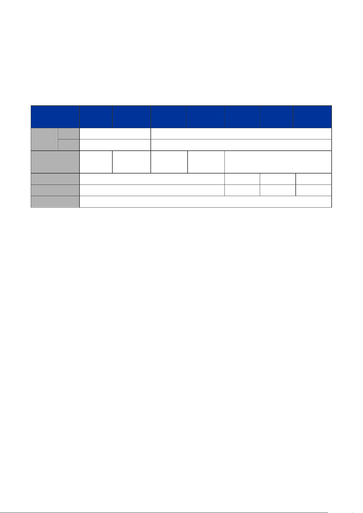
User’s Manual of SGSW-24040 / 24240 Series
22
trend of higher power demand. Hence, the IEEE 802.3at Power over Ethernet pre-standard is defined to allow delivery of
maximum up to 30 Watts input power to per PoE device. The IEEE 802.3at Power over Ethernet pre-standard is an ideal
solution to fulfill the high power requirements directly via the RJ-45 Port interface. Compliant with IEEE 802.3at, the
SGSW-24040HP possesses stronger power capability than the existing 802.3af PoE Switch.
The below table lists the major hardware difference between the series model:
Model
(SGSW Series)
Copper 8 24
Interface
Fiber 24, 100FX compatible 4, 100FX compatible
Redundant Power -
PoE Mode - af af af / at
PoE Budget - 220W 380W 360W
Stack Capability Hardware stacking, up to 16 units
24240 24240R 24040 24040R 24040P 24040P4 24040HP
-48V DC
-
(-30V~-60V)
-48V DC
-
(-30V~-60V)
1.3 How to Use This Manual
This User Manual is structured as follows:
Section 2, INSTALLATION
The section explains the functi ons of the Switch and how to physically install the Managed Swit ch.
Section 3, SWITCH MANAGEMENT
The section contains the information about the software function of the Managed Switch.
Section 4, WEB CONFIGURATION
The section explains how to manage the Managed Sw itch by Web interface.
Section 5, COMMAND LINE INTERFACE
The section describes how to use the Command Line interface (CLI).
Section 6, CLI CONFIGURATION
The section explains how to manage the Managed Switch by Command Line interface.
Section 7, SWITCH OPERATION
The chapter explains how to does the switch operation of the Managed Switch.
Section 8, POWER OVER ETHERNET OVERVIEW
The chapter introduce the I EEE 802.3af PoE st a ndar d and PoE provision of the Managed Switch.
Section 9, TROUBSHOOTING
The chapter explains how to trouble shooting of the Managed Switch.
Appendix A
The section contains cab le inf or mat ion of the Managed Switch.
Page 23

User’s Manual of SGSW-24040 / 24240 Series
23
1.4 Product Features
Physical Port
SGSW-24040 / SGSW-24040R
24-Port 10/100/1000Base-T Gigabit Ethernet RJ-45
4 100/1000Base-X SFP slots, shared with Port-21 to Port-24
RS-232 DB9 console interface for Switch basic management and setup
2 High-performance 5GbE Stacking interface
SGSW-24040P / SGSW-24040P4 / SGSW-24040HP
24-Port 10/100/1000Base-T Gigabit Ethernet RJ-45 with IEEE 802.3af PoE Injector (SGSW-240 40P / 24040P4)
24-Port 10/100/1000Base-T Gigabit Ethernet RJ-45 with IEEE 802.3af / 802.3at PoE Injector (SGSW-24040HP)
4 100/1000Base-X SFP slots, shared with Port-21 to Port-24
RS-232 DB9 console interface for Switch basic management and setup
2 High-performance 5GbE Stacking interface
SGSW-24240 / SGSW-24240R
24 100/1000Base-X mini-GBIC/SFP slots
8-Port 10/100/1000Base-T Gigabit Ethernet RJ-45, shared with Port-1 to Port-8
RS-232 DB9 console interface for Switch basic management and setup
2 High-performance 5GbE Stacking interface
Layer 2 Features
■ Prevents packet loss with back pressure (Half-Duplex) and IEEE 802.3x PAUSE frame flow control (Full-Duplex)
■ High performance of Store-and-Forward architecture, broadcast storm control and runt/CRC filtering eliminates
erroneous packets to optimize the network bandwidth
■ Storm Control supp or t:
− Broadcast / Multicast / Unknown-Unicast
■ Support VLAN
− IEEE 802.1Q Tagged VLAN
− Up to 255 VLANs groups, out of 4094 VLAN IDs
− Provider Bridging (VLAN Q-in-Q) support (IEEE 802.1ad)
− Private VLAN Edge (PVE)
− Voice VLAN
■ Support Span ning Tree Protocol
− STP, IEEE 802.1D Spanning Tree Protocol
− RSTP, IEEE 802.1w Rapid Spanning Tree Protocol
− MSTP, IEEE 802.1s Multiple Spanning Tree Protocol, spanning tree by VLAN
− BPDU Guard
■ Support Link Aggregation
Page 24

User’s Manual of SGSW-24040 / 24240 Series
24
− 802.3ad Link Aggregation Control Protocol (LACP)
− Cisco ether-channel (Static Trunk)
− Maximum 12 trunk groups, up to 16 ports per trunk group
− Up to 16Gbps bandwidth(Duplex Mode)
■ Provide Port Mirror (many-to-1)
■ Port Mirroring to monitor the incoming or outgoing traffic on a particular port
Quality of Service
■ Ingress Shaper and Egress Rate Limit per port bandwidth control
■ 4 priority queues on all switch ports
■ Traffic classification:
- IEEE 802.1p CoS
- TOS / DSCP / IP Precedence of IPv4/IPv6 packets
- IP T CP /U DP port number
- Typical network application
■ Strict priority and Weighted Round Robin (WRR) CoS policies
■ Supports QoS and In/Out bandwidth control on each port
■ Traffic-policing policies on the switch port
■ QoS Control List Wizard makes QoS creation and configuration easier and more quickly
■ DSCP remarking
Multicast
■ Supports IGMP Snooping v1, v2 and v3
■ Querier mode support
■ IGMP Snooping port filtering
■ Multicast VLAN Registration (MVR) support
Security
■ IEEE 802.1x Port-Based / MAC-Based network access authentication
■ Built-in RADIUS client to co-operate with the RADIUS servers
■ TACACS+ login users access authentication
■ RADIUS / TACACS+ users access authentication
■ IP-Based Access Control List (ACL)
■ MAC-Based Access Control List
■ Source MAC / IP address binding
■ DHCP Snooping to filter un-trusted DHCP messages
■ Dynamic ARP Inspection discards ARP packets with invalid MAC address to IP address binding
■ IP Source Guard preven t s IP spoofing attacks
■ Auto DoS rule to defend DoS attack
■ IP address access management to prevent unauthorized intruder
Page 25

25
Management
■ Switch Management Interfaces
- Console / Telnet Command Line Interface
- Web swit ch manage ment
- SNMP v1, v2c, and v3 switch management
- SSH / SSL secure access
■ Four RMON groups (history, statistics, alarms, and events)
■ IPv6 IP Address / NTP / DNS management
■ Built-in Trivial File Transfer Protocol (TFTP) client
■ BOOTP and DHCP for IP address assignment
■ Firmware upload/download via HTTP / TFTP
■ DHCP Relay
■ User Privilege levels control
■ NTP (Network Time Protocol)
■ Link Layer Discovery Protocol (LLDP) Protocol
User’s Manual of SGSW-24040 / 24240 Series
■ Cable Diagnostic technology provides the mechanism to detect and report potential cabling is sues
■ Reset button for system reboot or reset to factory default
■ PLANET Smart Discovery Utility for deploy management
■ ICMPv6
Stacking
■ Hardware stack up to 16 units and 384 ports
■ Stacki ng arch itecture supports Chain and Ring mode
■ Mirror across stack
■ Link Aggregation groups spanning multip le switches in a stack
■ Hardware learning with MAC table synchronization across stack
Redundant Power System (SGSW-24040R / 24240R)
■ 100~240V AC / 48V DC Dual power redundant
■ Active-active redundant power failure protection
■ Backup of catastrophic power failure on one supply
■ Fault tolerance and resilience.
Page 26

Power over Ethernet (SGSW-24040P / 24040P4 / 24040HP Only)
■ Complies with IEEE 802.3af Power over Ethernet End-Span PSE
■ Complies with IEEE 802.3at high-power Power over Ethernet End-Span PSE (SGSW-24040HP only)
■ Up to 24 ports for IEEE 802.3af devices powered
■ Up to 24 ports for IEEE 802.3at devices powered (SGSW-24040HP only)
■ Support PoE Power up to 15.4 watts for each PoE ports
■ Support PoE Power up to 30.8 watts for each PoE ports (SGSW-24040HP only)
■ Auto detect powered device (PD)
■ Circuit protection prevent power interference between ports
■ Remote power feeding up to 100m
■ PoE Management
■ Total PoE power budget control
■ Pert port PoE function enable/disable
■ PoE Port Power feeding priority
■ Per PoE port power limit
■ PD classification detection
1.5 Product Specification
SGSW Stackable Copper models
Product SGSW-24040 SGSW-24040R
Hardware Specificati on
Copper Ports 24 10/ 100/1000Base-T RJ-45 Auto-MDI/MDI-X ports
SFP/mini-GBIC Slots 4 SFP interfaces, shared with Port-21 to Port-24
Console Port 1 x RS-232 DB9 serial port (115200, 8, N, 1)
Stacking Ports 2 5GbE / Cross-HDMI interface
Switch Fabric 68Gbps / non-blocking
Address Table 8K entries, automatic source addres s lear n ing and age ing
Share data Buffer 1392 kilobytes
Switch Processing Scheme Store-and-Forward
Flow Control
IEEE 802.3x Pause Frame for Full-Duplex
Back pressure for Half-Duplex
Jumbo Frame 10Kbytes
Reset Button
Dimension (W x D x H)
Weight
< 5 seconds: System reboot
> 10 seconds: Factory Default
440 x 200 x 44.5 mm, 1U high
SGSW-24040: 3.0kg
Page 27
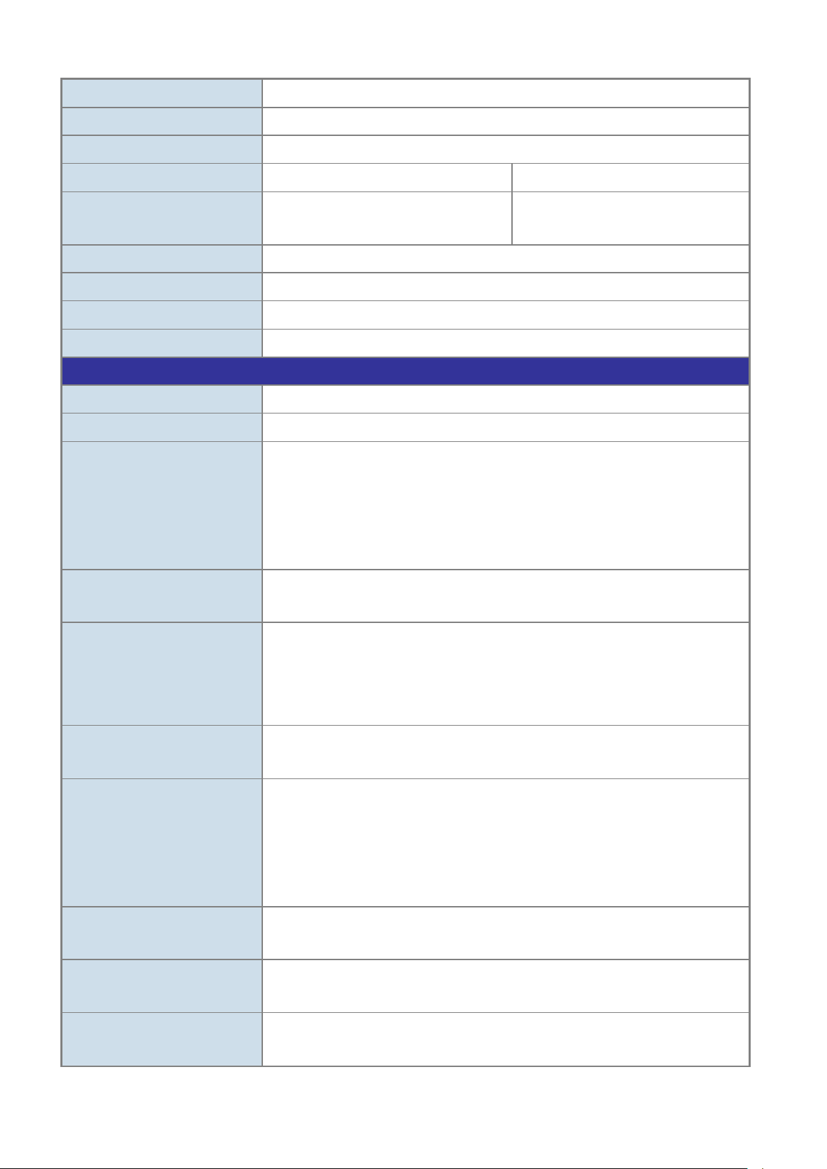
User’s Manual of SGSW-24040 / 24240 Series
27
SGSW-24040R: 3.1kg
LED Power, Link/Act and speed per Gigabit port
Power Consumption Max. 30.2 watts / 102.98 BTU
Power Requirement – AC
Power Requirement – DC
Stacking Numbers 16
Stacking Bandwidth 10Gbps Full-Duplex
Stack ID Display 7-Segment LED Display (1~9, A~F,0)
ESD Protection 6KV DC
Layer 2 Function
Basic Management Interfaces Console, Telnet, Web Browser, SNMPv1, v2c and v3
Secure Management Interfac e SSH, SSL, SNMP v3
Port disable/enable.
Auto-negotiation 10/100/1000Mbps full and half duplex mode selection.
Port configuration
Flow Control disable / enable.
Bandwidth control on each port.
Power saving mode control
AC 100~240V, 50/60Hz AC 100~240V, 50/60Hz
---
-48V DC @ 0.6A
Range: -30 ~ -60V
Port Status
VLAN
Port trunking
QoS
IGMP Snooping
Access Control List
Display each port’s speed duplex mode, link status, Flow control status.
Auto negotiation status, trunk status.
802.1Q Tagged Based VLAN ,up to 255 VLAN groups
Q-in-Q
Private VLAN
Voice VLAN
IEEE 802.3ad LACP / Static Trunk
Support 12 groups of 16-Port trunk support
Traffic classification based, Strict priority and WRR
4-level priority for switching
- Port Number
- 802.1p priority
- DS/TOS field in IP Packet
IGMP (v1/v2) Snooping, up to 255 multicast Groups
IGMP Querier mode support
IP-Based ACL / MAC-Based ACL
Up to 256 entries
SNMP MIBs
RFC-1213 MIB-II
IF-MIB
Page 28

28
RFC-1493 Bridge MIB
RFC-1643 Ethernet MIB
RFC-2863 Interface MIB
RFC-2665 Ether-Like MIB
RFC-2737 Entity MIB
RFC-2618 RADIUS Client MIB
RFC-2933 IGMP-STD-MIB
RFC3411 SNMP-Frameworks-MIB
IEEE 802.1X PAE
LLDP
MAU-MIB
Standards Conformance
Regulation Compliance FCC Part 15 Class A, CE
IEEE 802.3 10Base-T
User’s Manual of SGSW-24040 / 24240 Series
IEEE 802.3u 100Base-TX/100Base-FX
IEEE 802.3z Gigabit SX/LX
IEEE 802.3ab Gigabit 1000T
IEEE 802.3x Flow Control and Back pressure
IEEE 802.3ad Port trunk with LACP
Standards Compliance
IEEE 802.1D Spanning Tree protocol
IEEE 802.1w Rapid Spanning Tree protocol
IEEE 802.1s Multiple Spanning Tree
IEEE 802.1p Class of service
IEEE 802.1Q VLAN Tagging
IEEE 802.1x Port Authentication Network Control
IEEE 802.1ab Link Layer Discovery Protocol (LLDP)
SGSW Stackable Fiber models
Product SGSW-24240 SGSW-24240R
Hardware Specificati on
Copper Ports 8 10/ 100/1000Base-T RJ-45 Auto-MDI/MDI-X ports, shared with Port-1~Port-8
SFP/mini-GBIC Slots 24 100/1000Base-X Dual Speed SFP interfaces
Console Port 1 x RS-232 DB9 serial port (115200, 8, N, 1)
Stacking Ports 2 5GbE / Cross-HDMI interface
Switch Fabric 68Gbps / non-blocking
Address Table 8K entries, automatic source address learning and ageing
Page 29

29
Share data Buffer 1392 kilobytes
Switch Processing Scheme Store-and-Forward
User’s Manual of SGSW-24040 / 24240 Series
Flow Control
Jumbo Frame 10Kbytes
Reset Button
Dimension (W x D x H)
Weight
LED Power, Link/Act and speed per Gigabit port
Power Consumption Max. 30.2 watts / 102.98 BTU
Power Requirement – AC
Power Requirement – DC
Stacking Numbers 16
Stacking Bandwidth 10Gbps Full-Duplex
IEEE 802.3x Pause Frame for Full-Duplex
Back pressure for Half-Duplex
< 5 seconds: System reboot
> 10 seconds: Factory Default
440 x 200 x 44.5 mm, 1U high
SGSW-24040: 3.0kg
SGSW-24040R: 3.1kg
AC 100~240V, 50/60Hz AC 100~240V, 50/60Hz
---
-48V DC @ 0.6A
Range: -30 ~ -60V
Stack ID Display 7-Segment LED Display (1~9, A~F,0)
ESD Protection 6KV DC
Layer 2 Function
Basic Management Interfaces Console, Telnet, Web Browser, SNMPv1, v2c and v3
Secure Management Interfac e SSH, SSL, SNMP v3
Port disable/enable.
Auto-negotiation 10/100/1000Mbps full and half duplex mode selection.
Port configuration
Port Status
VLAN
Flow Control disable / enable.
Bandwidth control on each port.
Power saving mode control
Display each port’s speed duplex mode, link status, Flow control status.
Auto negotiation status, trunk status.
802.1Q Tagged Based VLAN ,up to 255 VLAN groups
Q-in-Q
Private VLAN
Voice VLAN
Port trunking
QoS
IEEE 802.3ad LACP / Static Trunk
Support 12 groups of 16-Port trunk support
Traffic classification based, Strict priority and WRR
4-level priority for switching
Page 30

User’s Manual of SGSW-24040 / 24240 Series
30
- Port Number
- 802.1p priority
IGMP Snooping
Access Control List
SNMP MIBs
- DS/TOS field in IP Packet
IGMP (v1/v2) Snooping, up to 255 multicast Groups
IGMP Querier mode support
IP-Based ACL / MAC-Based ACL
Up to 256 entries
RFC-1213 MIB-II
IF-MIB
RFC-1493 Bridge MIB
RFC-1643 Ethernet MIB
RFC-2863 Interface MIB
RFC-2665 Ether-Like MIB
RFC-2737 Entity MIB
RFC-2618 RADIUS Client MIB
RFC-2933 IGMP-STD-MIB
RFC3411 SNMP-Frameworks-MIB
IEEE 802.1X PAE
LLDP
MAU-MIB
Standards Conformance
Regulation Compliance FCC Part 15 Class A, CE
IEEE 802.3 10Base-T
IEEE 802.3u 100Base-TX/100Base-FX
IEEE 802.3z Gigabit SX/LX
IEEE 802.3ab Gigabit 1000T
IEEE 802.3x Flow Control and Back pressure
IEEE 802.3ad Port trunk with LACP
Standards Compliance
IEEE 802.1D Sp ann ing Tree protocol
IEEE 802.1w Rapid Spanning Tree protocol
IEEE 802.1s Multiple Spanning Tree
IEEE 802.1p Class of service
IEEE 802.1Q VLAN Tagging
IEEE 802.1x Port Authentication Network Control
IEEE 802.1ab Link Layer Discovery Protocol (LLDP)
Page 31

User’s Manual of SGSW-24040 / 24240 Series
31
SGSW Stackable PoE models
Product SGSW-24040P SGSW-24040P4 SGSW-24040HP
Hardware Specificati on
Copper Ports 24 10/ 100/1000Base-T RJ-45 Auto-MDI/MDI-X ports
SFP/mini-GBIC Slots 4 SFP interfaces, shar ed w ith Port -21 to Port-24
Console Port 1 x RS-232 DB9 serial port (115200, 8, N, 1)
Stacking Ports 2 5GbE / Cross-HDMI interface
Switch Fabric 68Gbps / non-blocking
Address Table 8K entries, automatic source address learning and ageing
Share data Buffer 1392 kilobytes
Switch Processing Scheme Store-and-Forward
Flow Control
Jumbo Frame 10Kbytes
Reset Button
Dimension (W x D x H)
Weight
LED Power, Link/Act and speed per Gigabit port
Power Consumption
Power Requirement – AC
Stacking Numbers 16
Stacking Bandwidth 10Gbps Full-Duplex
Stack ID Display 7-Segment LED Display (1~9, A~F,0)
ESD Protection 6KV DC
IEEE 802.3x Pause Frame for Full-Duplex
Back pressure for Half-Duplex
< 5 seconds: System reboot
> 10 seconds: Factory Default
440 x 300 x 44.5 mm, 1U high
4.5kg
Max. 290 watts /
989 BTU
AC 100~240V, 50/60Hz AC 100~240V, 50/60Hz AC 100~240V, 50/60Hz
Max. 430.2 watts /
1467 BTU
Max. 432 watts /
1473 BTU
Power over Ethernet
PoE Standard IEEE 802.3af PoE / PSE IEEE 802.3af/at PoE / PSE
PoE Power Supply Type End-Span
PoE Power Output
Power Pin Assignment 1/2(+), 3/6(-)
PoE Power Budget 220 Watts 380 Watts 360 Watts
Number of PD @
PoE Ability
7Watts
Per Port 48V DC.
Max. 15.4 watts
24 24 24
Per Port 52V DC.
Max. 30.8 watts
Page 32
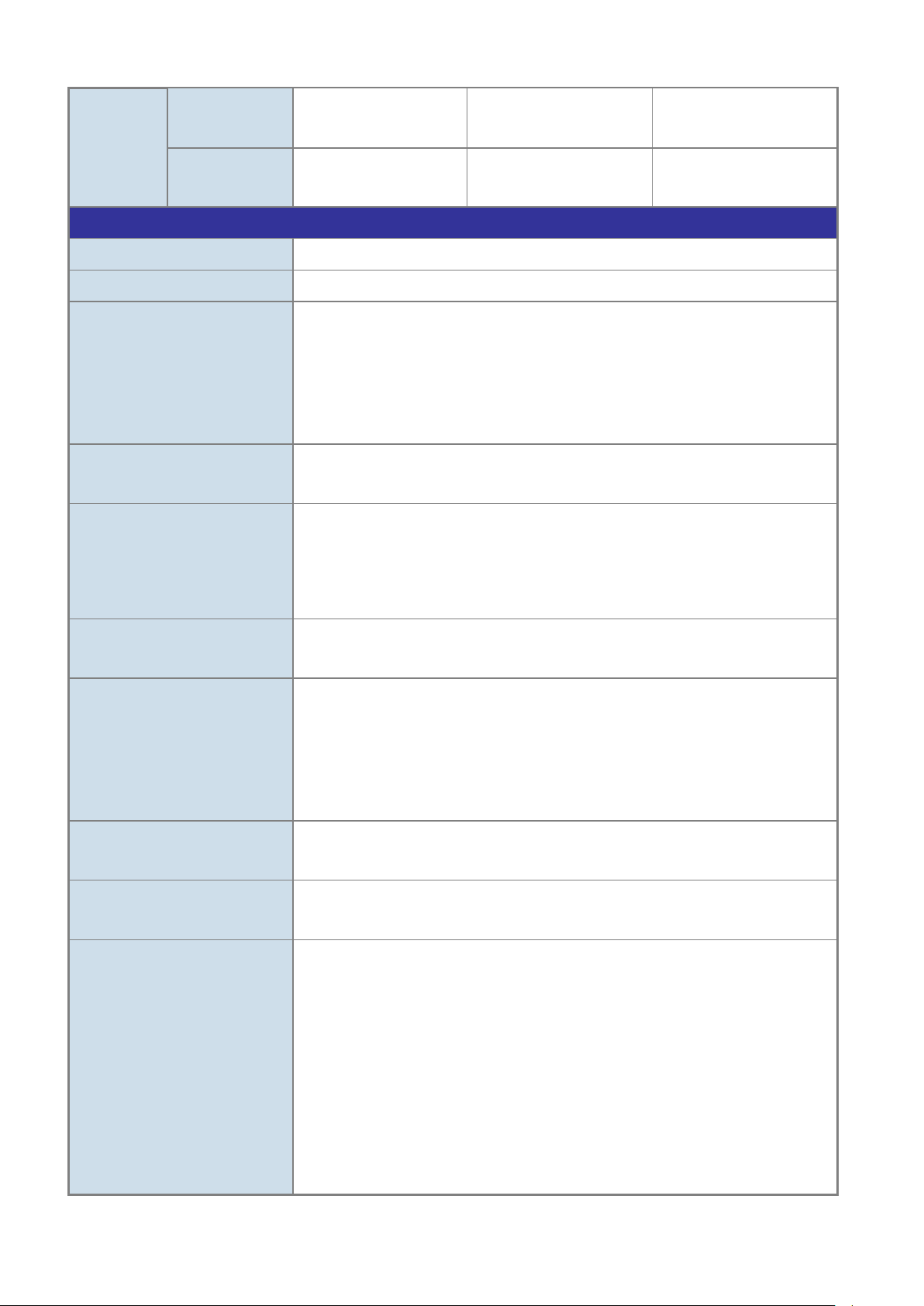
User’s Manual of SGSW-24040 / 24240 Series
32
Number of PD @
15.4Watts
Number of PD @
30.8Watts
Layer 2 Function
Basic Management Interfaces Console, Telnet, Web Browser, SNMPv1, v2c and v3
Secure Management Interfac e SSH, SSL, SNMP v3
Port configuration
Port Status
VLAN
14 24 23
- - 11
Port disable/enable.
Auto-negotiation 10/100/1000Mbps full and half duplex mode selection.
Flow Control disable / enable.
Bandwidth control on each port.
Power saving mode control
Display each port’s speed duplex mode, link status, Flow control status.
Auto negotiation status, trunk status.
802.1Q Tagged Based VLAN ,up to 255 VLAN groups
Q-in-Q
Private VLAN
Port trunking
QoS
IGMP Snooping
Access Control List
Voice VLAN
IEEE 802.3ad LACP / Static Trunk
Support 12 groups of 16-Port trunk support
Traffic classification based, Strict priority and WRR
4-level priority for switching
- Port Number
- 802.1p priority
- DS/TOS field in IP Packet
IGMP (v1/v2) Snooping, up to 255 multicast Groups
IGMP Querier mode support
IP-Based ACL / MAC-Based ACL
Up to 256 entries
RFC-1213 MIB-II
IF-MIB
RFC-1493 Bridge MIB
RFC-1643 Ethernet MIB
SNMP MIBs
RFC-2863 Interface MIB
RFC-2665 Ether-Like MIB
RFC-2737 Entity MIB
RFC-2618 RADIUS Client MIB
RFC-2933 IGMP-STD-MIB
Page 33

33
RFC3411 SNMP-Frameworks-MIB
IEEE 802.1X PAE
LLDP
MAU-MIB
Standards Conformance
Regulation Compliance FCC Part 15 Class A, CE
IEEE 802.3 10Base-T
IEEE 802.3u 100Base-TX/100Base-FX
IEEE 802.3z Gigabit SX/LX
IEEE 802.3ab Gigabit 1000T
IEEE 802.3x Flow Control and Back pressure
IEEE 802.3ad Port trunk with LACP
IEEE 802.1d Spanning tree protocol
IEEE 802.1w Rapid spanning tree protocol
User’s Manual of SGSW-24040 / 24240 Series
Standards Compliance
IEEE 802.1s Multiple spanning tree protocol
IEEE 802.1p Class of service
IEEE 802.1Q VLAN Tagging
IEEE 802.1x Port Authentication Network Control
IEEE 802.1ab LLDP
RFC 768 UDP
RFC 793 TFTP
RFC 791 IP
RFC 792 ICMP
RFC 2068 HTTP
RFC 1112 IGMP version 1
RFC 2236 IGMP version 2
IEEE 802.3af Power over Ethernet
IEEE 802.3at Power over Ethernet (Pre-Standard)
Page 34
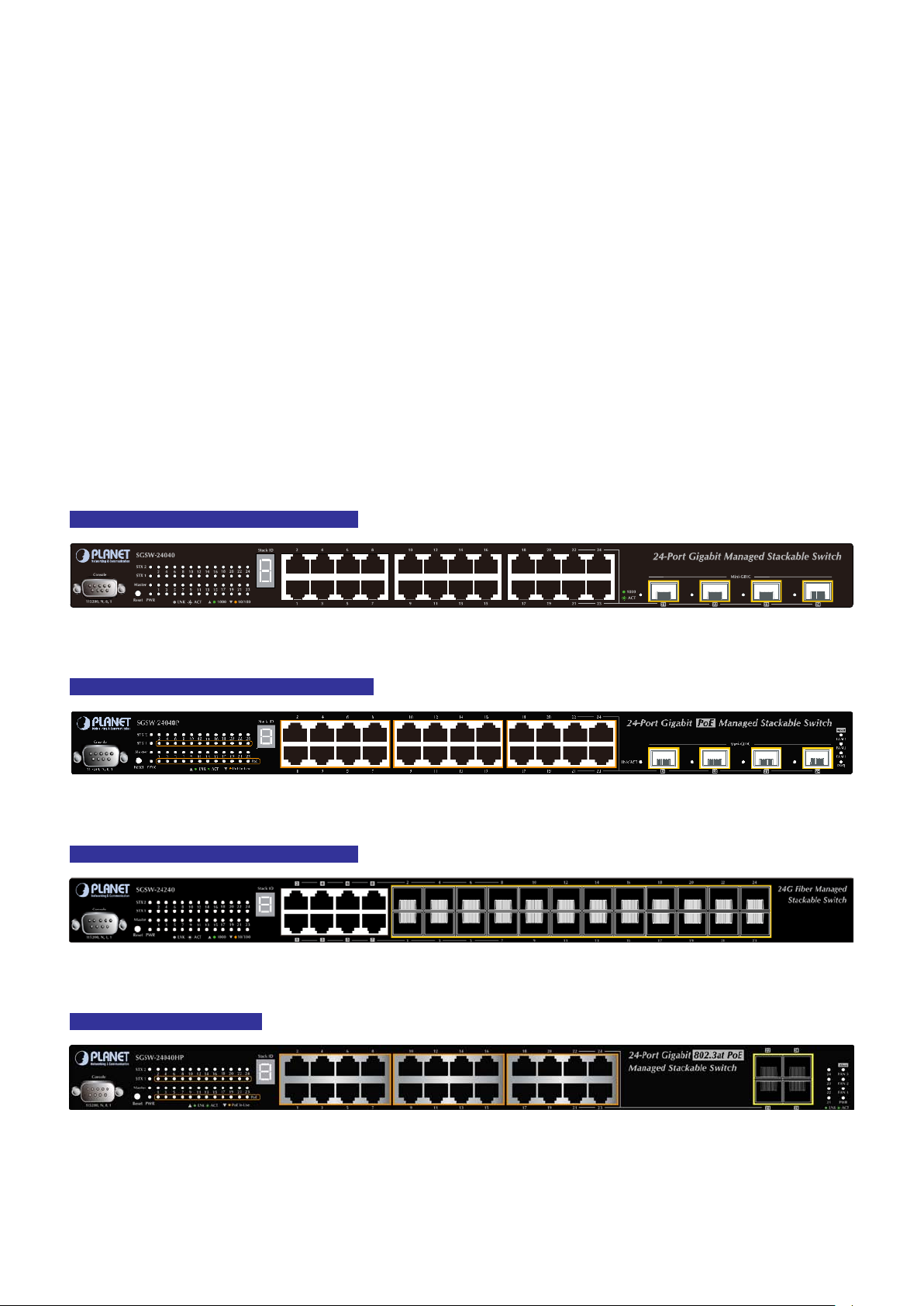
User’s Manual of SGSW-24040 / 24240 Series
34
2. INSTALLATION
This section describes the hardware features and installation of the Managed Switch on the desktop or rack mount. For easier
management and control of the Managed Switch, familiarize yourself with its display indicators, and ports. Front panel
illustrations in this chapter disp lay the unit LED indicators. Bef ore conne cting any net work d ev ice to t he M anaged Switch, please
read this chapter completely.
2.1 Hardware Description
2.1.1 Switch Front Panel
The unit front panel provides a simple interface monitoring the switch. Figure 2-1 to 2-3 show the front panel of the Managed
Switches.
SGSW-24040 / SGSW-24040R Front Panel
Figure 2-1 SGSW-24040 / SGSW-24040R front panel.
SGSW-24040P / SGSW-24040P4 Front Panel
Figure 2-2 SGSW-24040P / SGSW-24040P4 front panel.
SGSW-24240 / SGSW-24240R Front Panel
Figure 2-3 SGSW-24240 / SGSW-24240R front panel.
SGSW-24040HP Front Panel
Figure 2-4 SGSW-24040HP front panel.
Page 35

User’s Manual of SGSW-24040 / 24240 Series
35
■ Gigabit TP interface
10/100/1000Base-T Copper, RJ-45 Twist-Pair: Up to 100 meters.
■ Gigabit SFP slots
1000Base-SX/LX mini-GBIC slot, SFP (Small Factor Pluggable) transceiver module: From 550 meters (Multi-mode fiber),
up to 10/30/50/70/120 kilometers (Si ngle -mode fiber).
■ Console Port
The console port is a DB9, RS-232 male serial port co nnector. It is an interface for connecting a terminal directly. Through
the console port, it provides rich diagnostic information includes IP Address setting, factory reset, port manage me nt , link
status and system sett ing. Users can use the atta che d R S -23 2 cab le i n the p ac ka ge and connect to the console por t on th e
device. After the connection, users an run any terminal emulation program (Hyper Terminal, ProComm Plus, Telix, Winterm
and so on) to enter the startup screen of the device.
■ Reset button
At the left of front panel, the reset button is designed for reboot the Managed Switch without turn off and on the power. The
following is the summary table of Reset button functions:
Reset Button Pressed and Released Function
< 5 sec: System reboot Reboot the Managed Switch
Reset the Managed Switch to Factory Default configuration.
The Managed Switch will then reboot and load the default
settings as below:
> 5 sec: Factory Default
■ Stack ID
Each SGSW Managed Stackable Switch on a stack must have a unique “Stack ID”. There are 16 degrees (0~9, A~F) in the
rotary switch. The Stack ID is configured via Web or CLI management interface. Use the Stack ID to identify the location of
the real device.
。 Default Username: admin
。 Default Password: admin
。 Default IP address: 192.168.0.100
。 Subnet mask: 255.255.255.0
。 Default Gateway: 192.168.0.254
Stack ID is not equals to the Master Priority that configured in the manage ment inte r fac e.
■ Master LED
If master switch is fail or disconnected to the switch by stack port, the switch with least switch ID will become mast er.
Page 36

User’s Manual of SGSW-24040 / 24240 Series
36
with speed
2.1.2 LED Indications
The front panel LEDs in dic ate s instant status of port links, data activ ity and system power; help s monitor and troubl eshoot when
needed. Figure 2-4 & Figure 2-6 shows the LED indications of these Managed Switches.
SGSW-24040 / SGSW-24040R LED indication
Figure 2-4 SGSW-24040 / SGSW-24040R LED p ane l
■ System
LED Color Function
PWR Green
Master Green
STX1 Green
STX2 Green
■ 10/100/1000Base-T interfaces
LED Color Function
1000
Green
LNK/ACT
Lights to indicate that the Switch is powered on.
Blink to indicate the System is running under booting procedure.
Lights to indicate that the Switch is the Mas ter of the stack group.
Lights to indicate the stacking link through that port is successfully established.
Lights to indicate the stacking link through that port is successfully established.
Lights: To indicate the link through that port i s su cce ssfully establi shed with speed
1000Mbps
Blink: To indicate that the switch is actively sending or receiving data over that port.
Off: If L10/100 NK/ACT LED light-> indicate that the port is operating at 10Mbps or
100Mbps
If LNK/ACT LED Off -> ind ica te that the port is link down
Lights: To indicate the link through that port is successfully established
10Mbps or 100Mbps
10/100
Orange
LNK/ACT
Blink: To indicate that the switch is actively sending or receiving data over that port.
Off: If 1000 LNK/ACT LED light-> indicate that the port is operating at 1000Mbps
If 1000 LNK/ACT LED Off -> indicate that the port is link down
Page 37

User’s Manual of SGSW-24040 / 24240 Series
37
■ 1000Base-SX/LX SFP interfaces (Shared Port-21~Port-24)
LED Color Function
Lights: To indicate the link through that SFP port is successfully established with
1000
Green
LNK
Off: To indicate that the SFP port is link down
speed 1000Mbps
SGSW-24040P / SGSW-24040P4 / SGSW-24040HP LED indication
Figure 2-5 SGSW-24040P / SGSW-24040P4 LED panel
■ System
LED Color Function
PWR Green
Master Green
STX1 Green
STX2 Green
■ Alert
LED Color Function
PWR Alert Green Lights to indicate that the power supply failure
Lights to indicate that the Switch is powered on.
Blink to indicate the System is running under booting procedure.
Lights to indicate that the Switch is the Master of the stack group
Lights to indicate the stacking link through that port is successfully established.
Lights to indicate the stacking link through that port is successfully established.
FAN1 Alert Green Lights to indicate that the FAN1 failure
FAN2 Alert Green Lights to indicate that the FAN2 failure
FAN3 Alert Green Lights to indicate that the FAN3 failure
Page 38

38
■ 10/100/1000Base-T interfaces
LED Color Function
User’s Manual of SGSW-24040 / 24240 Series
Lights: To indicate the link through that port i s su cce ssfully establi shed with speed
10Mbps or 100Mbps or 1000Mbps
10/100/1000
Green
LNK/ACT
PoE In-Use Orange
■ 1000Base-SX/LX SFP interfaces (Shared Port-21~Port-24)
LED Color Function
1000
Green
LNK
Blink: To indicate that the switch is actively sending or receiving data over that port.
Off: If L10/100 NK/ACT LED light-> indicate that the port is operating at 10Mbps or
100Mbps
If LNK/ACT LED Off -> ind ica te that the port is link down
Lights: To indicate the port is providing 48VDC in-line power
Off: To indicate the connected device is not a PoE Powered Device (PD)
Lights: To indicate the link through that SFP port is successfully established with
speed 1000Mbps
Off: To indicate that the SFP port is link down
SGSW-24240 / SGSW-24240R LED indication
Figure 2-6 SGSW-24240 / SGSW-24240R LED p ane l
■ System
LED Color Function
Lights to indicate that the Switch is powered on.
PWR Green
Blink to indicate the System is running under booting procedure.
Master Green
Lights to indicate that the Switch is the Master of the stack group
Page 39
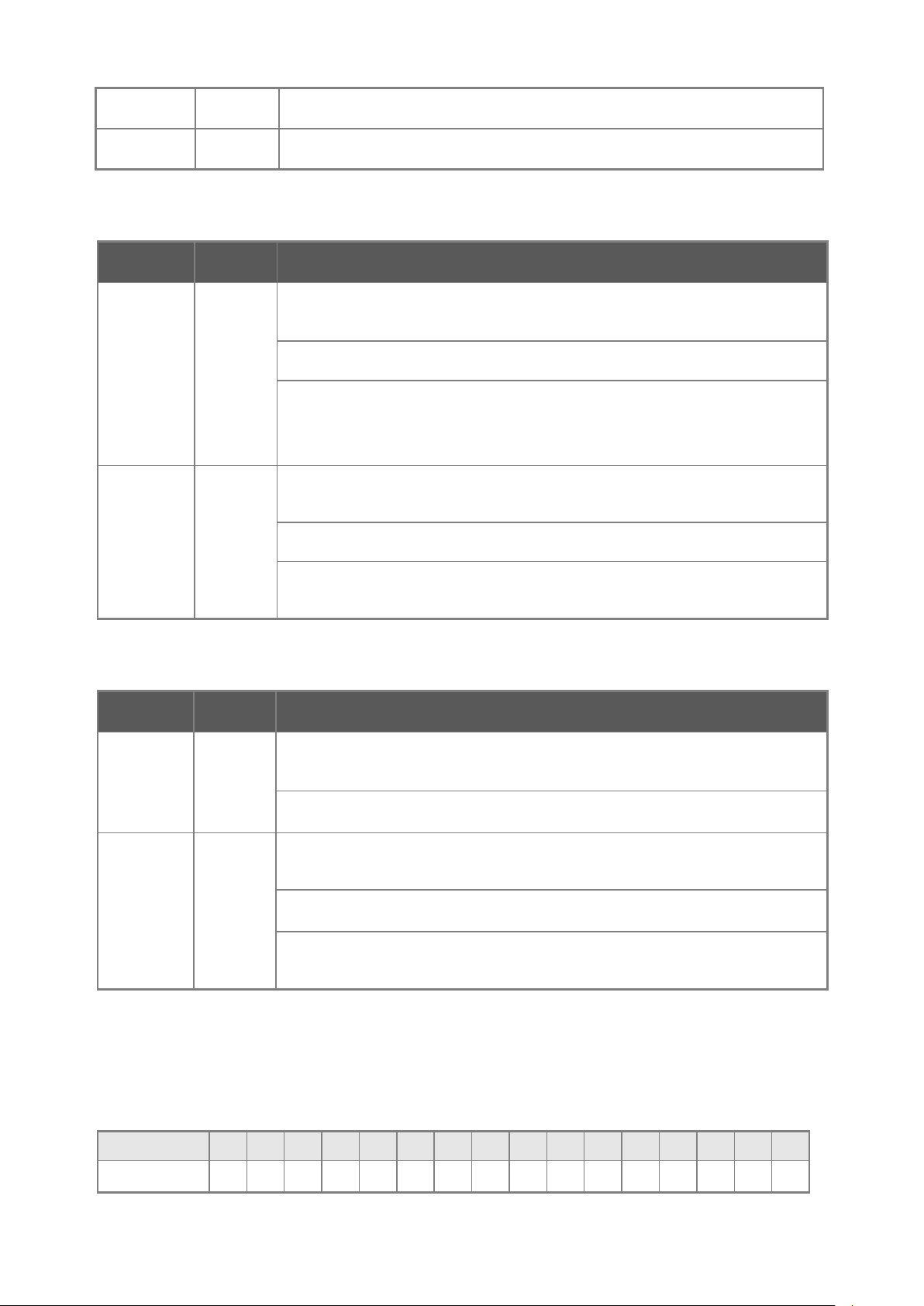
User’s Manual of SGSW-24040 / 24240 Series
39
with speed
with speed
STX1 Green
STX2 Green
■ 10/100/1000Base-T interfaces (Shared Port-1~Port-8)
LED Color Function
1000
Green
LNK/ACT
10/100
Orange
LNK/ACT
Lights to indicate the stacking link through that port is successfully established.
Lights to indicate the stacking link through that port is successfully established.
Lights: To indicate the link through that port is successfully est a bl i sh e d with speed
1000Mbps
Blink: To indicate that the switch is actively sending or receiving data over that port.
Off: If L10/100 NK/ACT LED light-> indicate that the port is operating at 10Mbps or
100Mbps
If LNK/ACT LED Off -> indicate that the port is link down
Lights: To indicate the link through that port is successfully established
10Mbps or 100Mbps
Blink: To indicate that the switch is actively sending or receiving data over that port.
Off: If 1000 LNK/ACT LED light-> indicate that the port is operating at 1000Mbps
■ 100 / 1000Base-X SFP interfaces
LED Color Function
Lights: To indicate the link through that SFP port is successfully established with
1000
Green
LNK
100
Orange
LNK/ACT
■ 7-Segment LED Display
Off: To indicate that the SFP port is link down
Lights: To indicate the link through that port is successfully established
Blink: To indicate that the switch is actively sending or receiving data over that port.
Off: If 1000 LNK/ACT LED light-> indicate that the port is operating at 1000Mbps
If 1000 LNK/ACT LED Off -> indicate that the port is link down
speed 1000Mbps
100Mbps
If 1000 LNK/ACT LED Off -> indicate that the port is link down
Stack ID (1~9, A~F, 0): To indicate the Switch ID of each SGSW Managed Switch. S w itch IDs are used to uniquely id enti f y
the Managed Switches within a stack. The Switch ID of each Managed Switch is shown on the display on the front of the
Managed Switch and is used widely in the web pages as well as in the CLI commands of the Stack group.
Stack ID 1 2 3 4 5 6 7 8 9 A. B. C. D. E. F. 0
Switch ID 1 2 3 4 5 6 7 8 9 10 11 12 13 14 15 16
Page 40
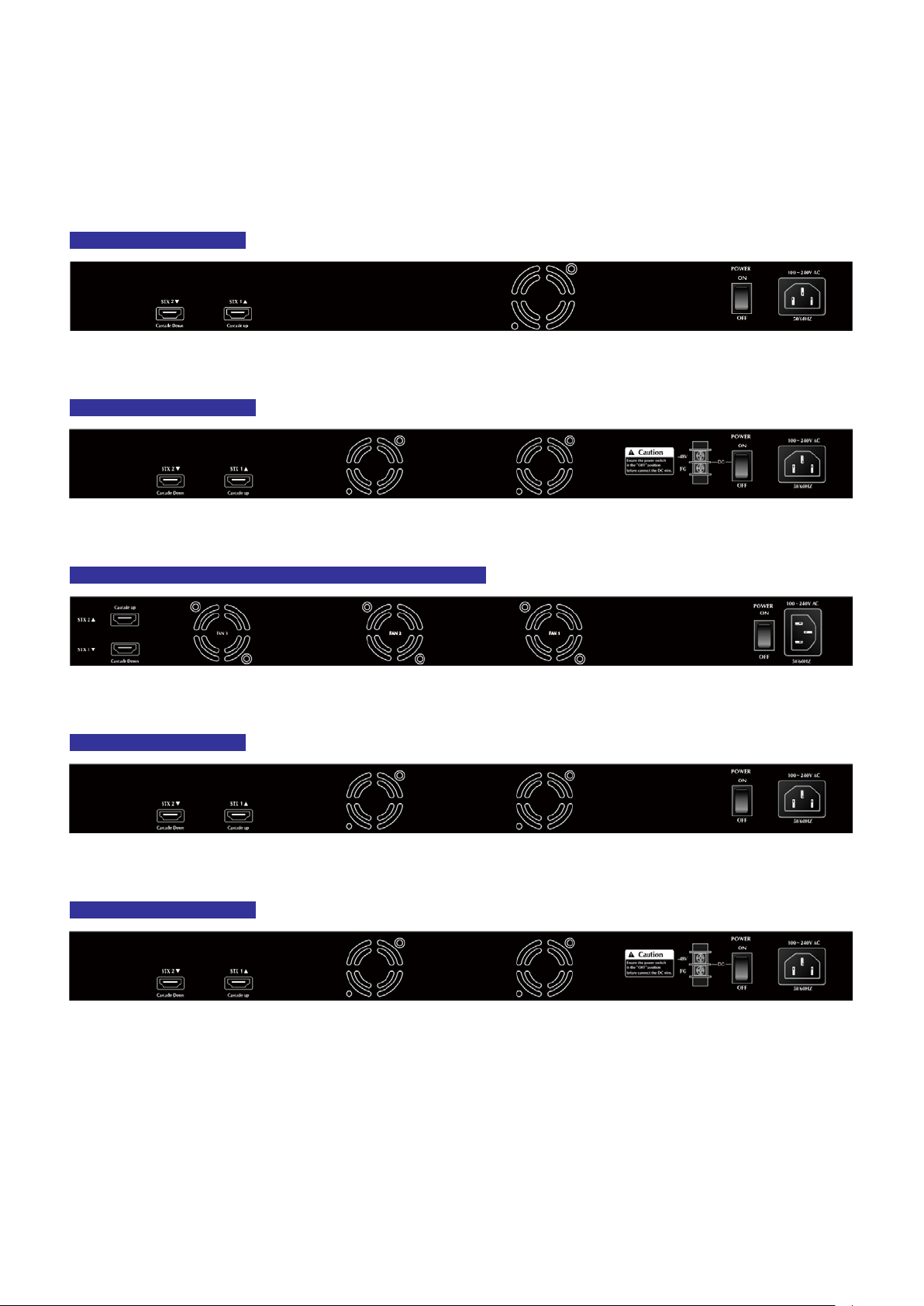
User’s Manual of SGSW-24040 / 24240 Series
40
2.1.3 Switch Rear Panel
The rear panel of the Managed Switch indicates an AC inlet power socket, which accepts input power from 100 to 240V AC,
50-60Hz. Figure 2-7 & Figure 2-11 shows the rear panel of these Managed Switches
SGSW-24040 Rear Panel
Figure 2-7 Rear panel of SGSW-24040
SGSW-24040R Rear Panel
Figure 2-8 Rear panel of SGSW-24040R
SGSW-24040P / SGSW-24040P4 / SGSW-24040HP Rear Panel
Figure 2-9 Rear panel of SGSW-24040P / SGSW-24040P4
SGSW-24240 Rear Panel
Figure 2-10 Rear panel of SGSW-24240
SGSW-24240R Rear Panel
Figure 2-11 Rear panel of SGSW-24240R
■ AC Power Receptacle
For compatibility with electric service in most areas of the world, the Managed Switch’s power supply automatically adjusts
to line power in the range 100-240VAC and 50/60 Hz.
Plug the female end of the power cord firmly into the receptalbe on the rear panel of the Managed Switch. Plug the other
end of the power cord into an electric service outlet then the power will be ready.
Page 41
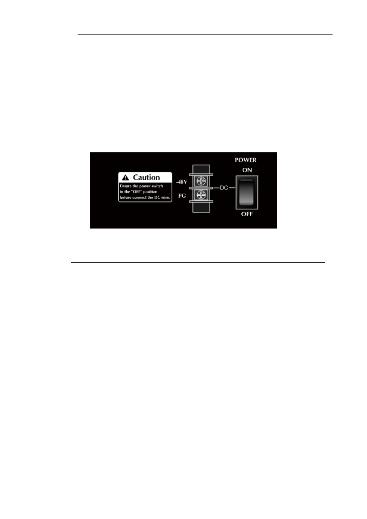
User’s Manual of SGSW-24040 / 24240 Series
41
should
witch from
e that the power
The device is a pow er-r equire d dev ic e, i t means, it will not work t ill it is powered. If your networks
active all the time, please consider using UPS (Uninterrupted Power Supply) for your device. It will
Power Notice:
■ DC Power Connector
The rear panel of the SGSW-24040R contains a power switch and a DC power connector, which accepts DC power input
voltage from -30V to -60V DC. Connect the power cable to the Managed Switch at the input terminal block. The size of the
two screws in the terminal block is M3.5.
prevent you from network data loss or network downtime.
In some area, installing a surge suppression device may also help to protect your Managed S
being damaged by unregulated surge or current to the Switch or the power adapter.
Figure 2-12 Rear Panel of SGSW-24040R
Before connect the DC p ower cable to the inpu t ter minal b lock of SGSW-24040R, ensur
Warning:
■ Stack ports
SGSW-24040 / 24040R Series
There are two High-Performance stack ports on the rear panel. One is STX1 / Cascade Down and the other is STX2 /
Cascade UP.
• When stacked, the STX1 / Cascade Down port should connect to the other switch’s STX2 / Cascade UP port and the
STX2 / Cascade UP port should connect to other switch’s STX1 / Cascade Down out.
• You can just use attached PLANET CB-STX50 or lon ger stack cable CB-STX200 connector to stack.
• The CB-STX50 and CB-STX200 are Cross-Overed HDMI cables; only attached PLANET stack cable can be used.
• Plug-and-play connection.
switch in the “OFF” position and the DC power is OFF
Page 42

User’s Manual of SGSW-24040 / 24240 Series
42
Figure 2-13 SGSW-24040 /24040R Series Stack Ports
Page 43
User’s Manual of SGSW-24040 / 24240 Series
43
Chapter 1,
45 tips. For more
2.2 Install the Switch
This section describes how to install your Managed Switch and make connections to the Managed Switch. Please read the
following topics and perfor m th e proc edur e s i n the order being presented. To install your Managed Switch on a desktop or shelf,
simply complete the following steps.
2.2.1 Desktop Installation
To install the Managed Switch on desktop or shelf, please follows these steps:
Step1: Attach the rubber feet to the recessed areas on the bottom of the Managed Switch.
Step2: Place the Managed Switch on the desktop or the shelf near an AC power source, as shown in Figure 2-14.
Figure 2-14 Place the Managed Switch on the desktop
Step3: Keep enough ventilation space between the Managed Switch and the surrounding objects.
When choosing a location, please keep in mind the environmental restrictions discussed in
Section 4, and Specification.
Step4: Connect the Managed Switch to network devices.
Connect one end of a standard network cable to the 10/100/1000 RJ-45 ports on the front of the Managed Switch
Connect the other end of the cable to the network devices such as printer servers, workstations or routers…etc.
Connection to the Managed Switch requires UTP Category 5 network cabling with RJinformation, please see the Cabling Specification in Appendix A.
Page 44

User’s Manual of SGSW-24040 / 24240 Series
44
use the screws supplied with the mounting brackets. Damage caused to the parts by
Step5: Supply power to the Managed Switch.
Connect one end of the power cable to the Managed Switch.
Connect the power plug of the power cable to a standard wall outlet.
When the Managed Switch receives power, the Power LED should remain solid Green.
2.2.2 Rack Mounting
To install the Managed Switch in a 19-inch standard rack, please follows the instructions described below.
Step1: Place the Managed Switch on a hard flat surface, with the front panel positioned towards the front side.
Step2: Attach the rack-mount bracket to each side of the Managed Switch with supplied screws attached to the package.
Figure 2-15 shows how to attach brackets to one side of the Managed Switch.
Figure 2-15 Attach brackets to the Managed Switch.
You must
using incorrect screws would invalidate the warranty.
Step3: Secure the brackets tightly.
Step4: Follow the same steps to attach the second bracket to the opposite side.
Step5: After the brackets are attached to the Managed Switch, use suitable screws to securely attach the brackets to the rack,
as shown in Figure 2-16.
Page 45

User’s Manual of SGSW-24040 / 24240 Series
45
Figure 2-16 Mounting SGSW-24040 in a Rack
Step6: Proceeds with the steps 4 and steps 5 of session 2.2.1 Desktop Installation to connect the network cabling and supply
power to the Managed Switch.
2.2.3 Installing the SFP transceiver
The sections describe how to insert an SFP transceiver into an SFP slot.
The SFP transceivers are hot-pluggable and hot-swappable. You can plug-in and out the transceiver to/from any SFP por t
without having to power down the Managed Switch. As the Figure 2-17 appears.
Figure 2-17 Plug-in the SFP transceiver
Page 46

User’s Manual of SGSW-24040 / 24240 Series
46
Switch. If you insert a SFP transceiver that is
Approved PLANET SFP Transceivers
PLANET Managed Switch support s both Single mode and Multi-mode SFP transceiver. The following list of approved PLANET
SFP transceivers is correct at the time of publication:
■ MGB-SX SFP (1000BASE-SX SFP transceiver / Multi-mode / 850nm / 220m~550m)
■ MGB-LX SFP (1000BASE-LX SFP transceiver / Single mode / 1310nm / 10km)
■ MGB-L30 SFP (1000BASE-LX SFP transceiver / Single mode / 1310nm / 30km)
■ MGB-L50 SFP (1000BASE-LX SFP transceiver / Single mode / 1310nm / 50km)
■ MGB-LA10 SFP (1000BASE-LX SFP transceiver / WDM Single mode / TX: 1310nm, RX: 1550nm/ 10km)
■ MGB-LB10 SFP (1000BASE-LX SFP transceiver / WDM Single mode / TX: 1550nm, RX: 1310nm / 10km)
It recommends using PLANET SFPs on the Managed
not supported, the Managed Switch will not recognize it.
Before connect the other Managed Switches, workst at ion or Media Converter.
1. Make sure both side of the SFP transceiver are with the same media type, for example: 1000Base-SX to 1000Base-SX,
1000Bas-LX to 1000Base-LX.
2. Check the fiber-optic cable type match the SFP transceiver model.
To connect to 1000Base-SX SFP transceiver, use the Multi-mode fiber cable- with one side must be male duplex LC
connector type.
To connect to 1000Base-LX SFP transceiver, use the Single-mode fiber cable-with one side must be male duplex LC
connector type.
Connect the fiber cable
1. Attach the duplex LC connector on the network cable into the SFP transceiver.
2. Connect the other end of the cable to a device – switches with SFP installed, fiber NIC on a workstation or a Media
Converter..
3. Check the LNK/ACT LED of the SFP slot on the front of the Managed Switch. Ensure that the SFP transceiver is oper ati ng
correctly.
4. Check the Link mode of the SFP port if the link failed. Co works with some fiber-NICs or Media Converters, set the Link
mode to “1000 Force” is needed.
Remove the transceiver module
1. Make sure there is no network activity by consult or check with the network administrator. Or through the management
interface of the switch/converter (if available) to disable the port in advance.
2. Remove the Fiber Optic Cable gently.
3. Turn the handle of the MGB module to horizontal.
4. Pull out the module gently through the handle.
Page 47

User’s Manual of SGSW-24040 / 24240 Series
47
he push bolts on the m odule. D irect p ull
Figure 2-18 Pull out the SFP transceiver
Never pull out the mo dule w ithout pu ll the han dle or t
out the module with violent could damage the module and SFP module slot of the Managed
Switch.
2.2.4 Connecting DC Power Supply – SGSW-24040R / 24240R
The SGSW-24040R supports -48VDC power input, connect the power cable to the switch at the input terminal block.
1. The size of the two screws in the terminal block is M3.5.
2. The terminals are marked “-48V”, “FG“.
3. Loosen the two screws so you can slide the DC cable beneath it. Insert the DC cable into the connector first, and screw it
down tight.
4. Connect the power cable to the DC power supply. After power up or reset, the Managed Switch performs a cold start
procedure.
Figure 2-19 -48VDC connector
Page 48

User’s Manual of SGSW-24040 / 24240 Series
48
Warning:
Before connect the DC power cable to the input terminal block of Managed Switch, ensure that the
power switch in the “OFF” position and the DC power is OFF
Page 49

User’s Manual of SGSW-24040 / 24240 Series
49
2.3 Stack Installation
SGSW-24040 / 24240 Series
The SGSW-24040 / 24240 series Managed Switch provides a switch stacking function to manage up to 16 switches using a
single IP address. And up to 384 Gigabit Ethernet ports can be managed by a stacking group and you can add ports and
functionality as needed. You can add SGSW-24040 / 24240 series switches as needed to support more netw ork clients,
knowing that your switchi ng fabric will sc ale to meet in crea si ng traffic demands.
Two types of stack topologies are supported by the SGSW-24040 / 24240 series:
Chain topology (same as a disconnected ring)
Ring topology
Please find the following picture for sample connection.
Figure 2-20 Chain Stack topology
Figure 2-21 Ring Stack topology
Page 50
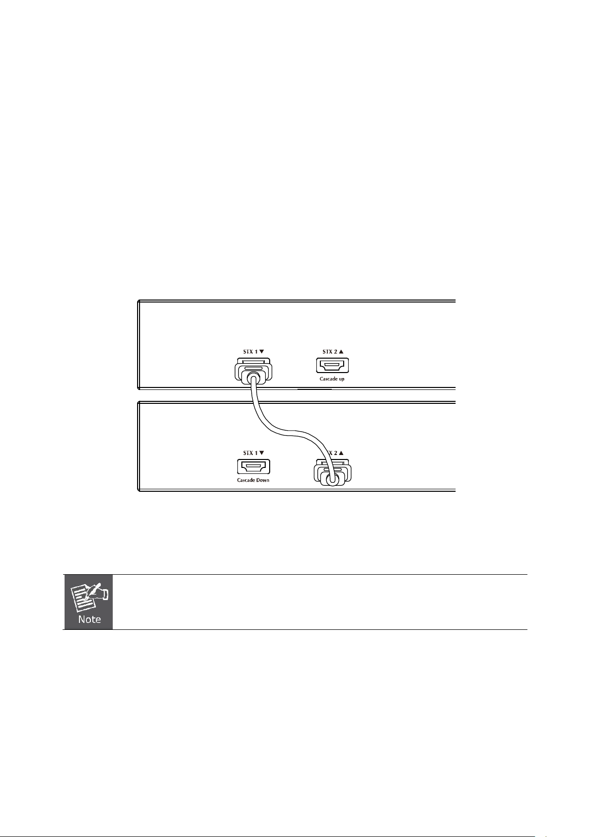
User’s Manual of SGSW-24040 / 24240 Series
50
other SGSW stackable
2.3.1 Connecting Stacking cable
Before attempting to connect stacking ports, verify that you have the required stack cables. T he following cab les are used to
connect stacked switches:
• CB-STX50: 50cm, Short stack cable –used to connect adjacent SGSW switches.
• CB-STX200: 200cm, Long / Redundant stack cable – used to connect the top and bottom SGSW switches of a stack.
There are two high-performance HDMI-like Stack ports on the rear panel for proprietary management stack. Only attached
PLANET CB-STX50 and CB-STX200 cross-overed HDMI cable can be used.
STEP-1: Plug one end of the cable in the “STX1 / Cascade Down” port and the other end to the ”STX2 / Cascade UP” port of
next device.
STEP-2: Repeat the step for every device in the stack cluster, then ending at last switch.
Figure 2-22 St a cki ng conn ect i on
STEP-3: If you wish to implement stack redundancy, use the long stack cable –CB-STX200 to connect the stack port mark ed
“STX1 / Cascade Down” on the bot t om sw it ch to t he p ort marked “STX2 / Cascade Up ” on t he to p sw it ch of the st a ck .
The stack port is for management and data packets to be transmitted between
switches, the stack ports can’t be configured with Layer 2 features via management interface.
STEP-4: Power up the stack switches.
2.3.2 Management Stacking
The stack operation of the SGSW Managed Switch supports Plug and Play Stacking connection and auto stack configur at ion.
STEP-5: Once the stack start operation, the Stack master be automatically elected without any configure. The Stack master is
Page 51

User’s Manual of SGSW-24040 / 24240 Series
51
indicated by a lit green “Master” LED on the front panel. As the Figure 2-23 appears.
Master LED
Figure 2-23 Stack Master with “Master” LED lit
Stack ID
STEP-6: When a SGSW Switch is added to the stack, a Switch ID is automatically assigned to the SGSW Switch. The
automatic SID assignment can be modified by choosing a different Switch ID on the Stack Configuration page. This
method allows Switch IDs to be assigned so that it is easier for the user to remember the ID of each switch.
STEP-7: Connect the RS-232 serial cable to the console port on the front of the stack master, then loin the SGSW Switch to
start the switch management. O r you can use the PLANET Smart Discovery Utility to displayt the IP address of the
stack and Web login the stack with this IP address. The default IP address of the SGSW Switch is 192.168.0.100.
Figure 2-24 Use PLANET Smart Discovery Utility to display the IP address of stack master
Page 52

User’s Manual of SGSW-24040 / 24240 Series
52
nly Master
1. The stack switch with least priority ID or MAC Address number will become Master. O
switch’s management interface (console, telnet, web and SNMP) is accessible.
It’s allow to build a stack of up to 16 PLANET SGSW Switches. If there is the space limitation or power issue and you wish to
stack all the switches in different racks, use long stack cables “CB-STX200” to connect two stacks.
2m stack cable CB-STX200 2m stack cable CB-STX200
Figure 2-25 Separated Stack connection
CB-STX50
Page 53

User’s Manual of SGSW-24040 / 24240 Series
53
3. SWITCH MANAGEMENT
This chapter explains the methods that you can use to configure management access to the Managed Switch. It describes the
types of management applications and the communication and management protocols that deliver data between your
management device (workstation or personal computer) and the system. It also contains information about port connection
options.
This chapter covers the following topics:
Requirements
Management Access Overview
Administration Console Access
Web Management Access
SNMP Access
Standards, Protocols, and Related Reading
3.1 Requirements
Workstations of subscribers running Windows 98/ME, NT4.0, 2000/XP, MAC OS9 or later, Linux, UNIX or other
platform compatibl e with TCP/IP protocols.
Workstation installed with Ethernet NIC (Network Interface Card)
Serial Port connect (Terminal)
• Above PC with COM Port (DB9 / RS-232) or USB-to-RS-232 converter
Ethernet Port connect
• Network cables - Use standard network (UTP) cables with RJ45 connectors.
Above Workstation installed with WEB Browser and JA VA runtime environment Plug-in
It is recommended to use Internet Explore 7.0 or above to access Managed Switch.
Page 54

User’s Manual of SGSW-24040 / 24240 Series
54
3.2 Management Access Overview
The Managed Switch gives you the flexibility to access and manage it using any or all of the following methods:
An administrati on console
Web browser interface
An external SNMP-based network management application
The administration console and Web browser interface support are embedded in the Managed Switch software and are
available for immediate use. Each of these management methods has their own advantages. Table 3-1 compares the three
management methods.
Method Advantages Disadvantages
Console
Web Browser
SNMP Agent
• No IP address or subnet needed
• Text-based
• Telnet functionality and HyperTerminal
built into Windows
95/98/NT/2000/ME/XP operating
systems
• Secure
• Ideal for configuring the switch remotely
• Compatible with all popular browsers
• Can be accessed from any location
• Most visually appealing
• Communicates with switch functions at
the MIB level
• Based on open standards
• Must be near switch or use dial-up connect ion
• Not convenient for remote users
• Modem connection may prove to be unreliable
or slow
• Security can be compromised (hackers need
only know the IP address and subnet mask)
• May encounter lag times on poor connections
• Requires SNMP manager software
• Least visually appealing of all three methods
• Some settings require calculations
• Security can be compromised (hackers need
only know the community name)
Table 3-1 Management Methods Comparison
3.3 Administration Console
The administration console is an interna l, chara cter -oriented, and command line user interface for performing system
administration such as displaying statistics or changing option settings. Using this method, you can view the administration
console from a terminal, personal computer, Apple Macintosh, or workstation connected to the switch's console (serial) port.
There are two ways to use this management method: via direct access or modem port access. The following sections describe
these methods. For more information about using the con sol e, refer to Chapter 5 Command Line Interface Console
Management.
Page 55
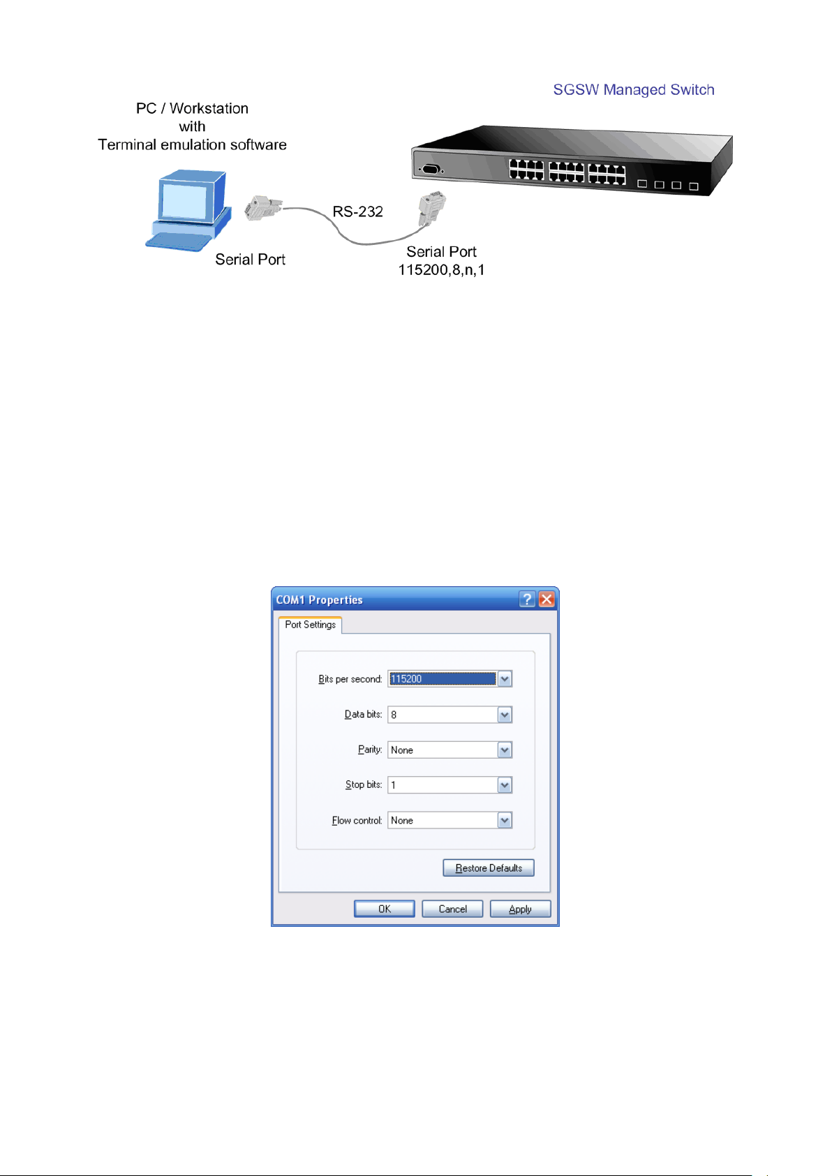
User’s Manual of SGSW-24040 / 24240 Series
55
Figure 3-1 Console management
Direct Access
Direct access to the administration console is achieved by directly connecting a terminal or a PC equipped with a
terminal-emulation program (such as HyperTerminal) to the Managed Switch console (serial) port.
When using this management method, a straight DB9 RS-232 cable is required to connect the switch to the PC. After
making this connection, configure the terminal-emulation program to use the following parameters:
The default parameters are:
115200 bps
8 data bits
No parity
1 stop bit
Figure 3-2 Terminal parameter settings
You can change these settings, if desired, after you log on. This management method is often preferred becau se you can
remain connected and monitor the system during system reboots. Also, certain error messages are sent to the serial port,
regardless of the interface through which the associated action was initiated. A Macintosh or PC attachment can use any
terminal-emulation progra m for connect ing to th e ter minal serial port . A workstation attachment under U NIX can use a n emu lator
such as TIP.
Page 56
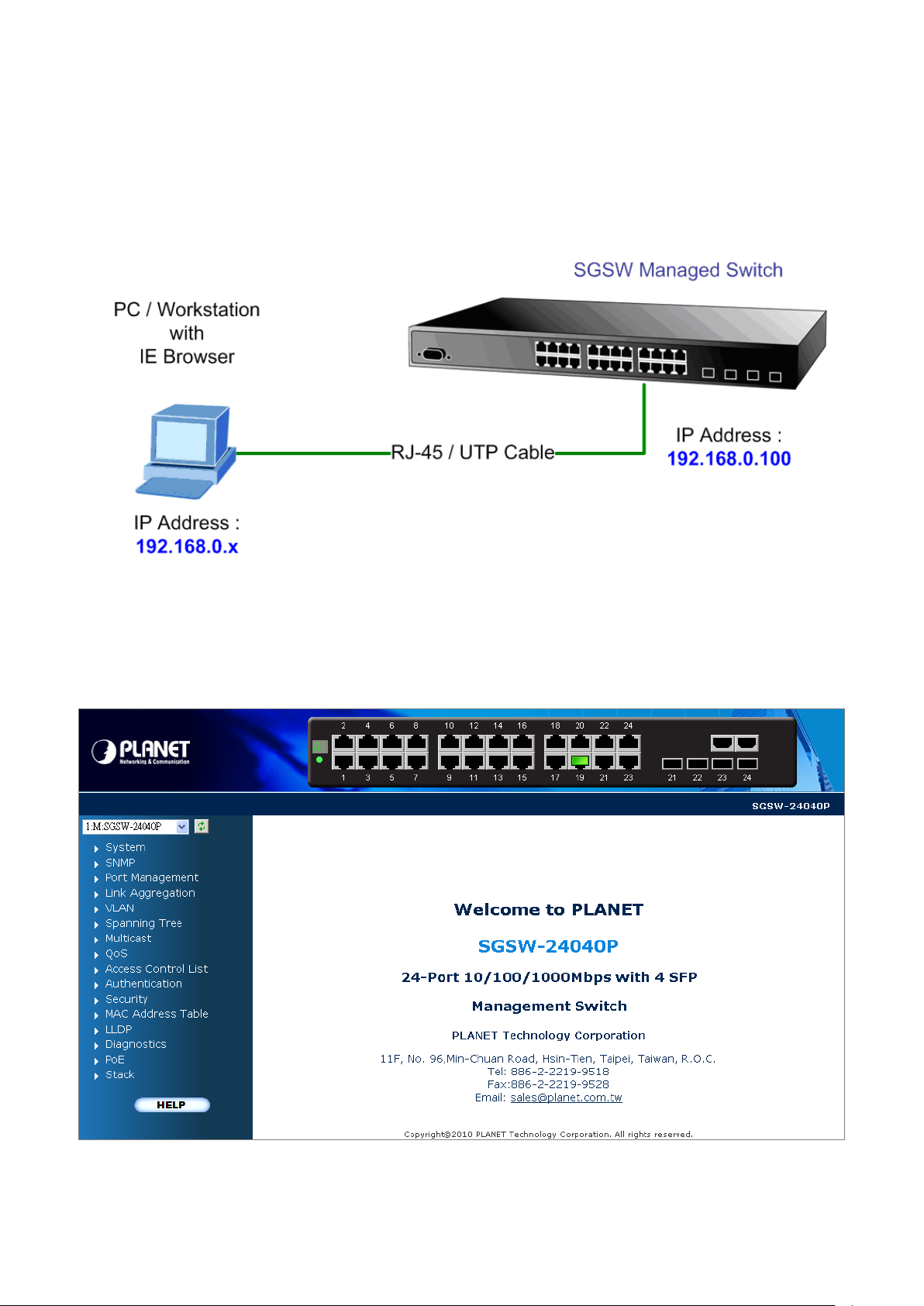
User’s Manual of SGSW-24040 / 24240 Series
56
3.4 Web Management
The Managed Switch offers management features that allow users to manage the Managed Switch from anywhere on the
network through a sta ndard brow ser such as M icros oft Intern et Ex plorer. After you set up yo ur IP addr ess for the sw itch, y ou can
access the Managed Switch's Web interface applications directly in your Web browser by entering the IP address of the
Managed Switch.
Figure 3-3 Web management
You can then use your Web browser to list and manage the Managed Switch configur ation p arameter s from one centr al locati on,
just as if you were directly connected to the Managed Switch's console port. Web Management requires either Microsoft
Internet Explorer 6.0 or later , Safari or Mozilla Firefox 1.5 or later.
Figure 3-4 Web main screen of Managed Switch
Page 57

User’s Manual of SGSW-24040 / 24240 Series
57
3.5 SNMP-Based Network Management
You can use an external SNMP-based application to configure and manage the Managed S witch, such as SNMPc Network
Manager, HP Openview Network Node Management (NNM) or What’s Up Gold. This management method requires the SNMP
agent on the switch and the SNMP Network Management Station to use the same community string. This management
method, in fact, uses two community strings: the get community string and the set community string. If the SNMP Net-work
management Station only knows the set community string, it can read and write to the MIBs. However, if it only knows the get
community string, it can only read MIBs. The default gets and sets community strings for the Managed Switch are public.
Figure 3-5 SNMP management
Page 58
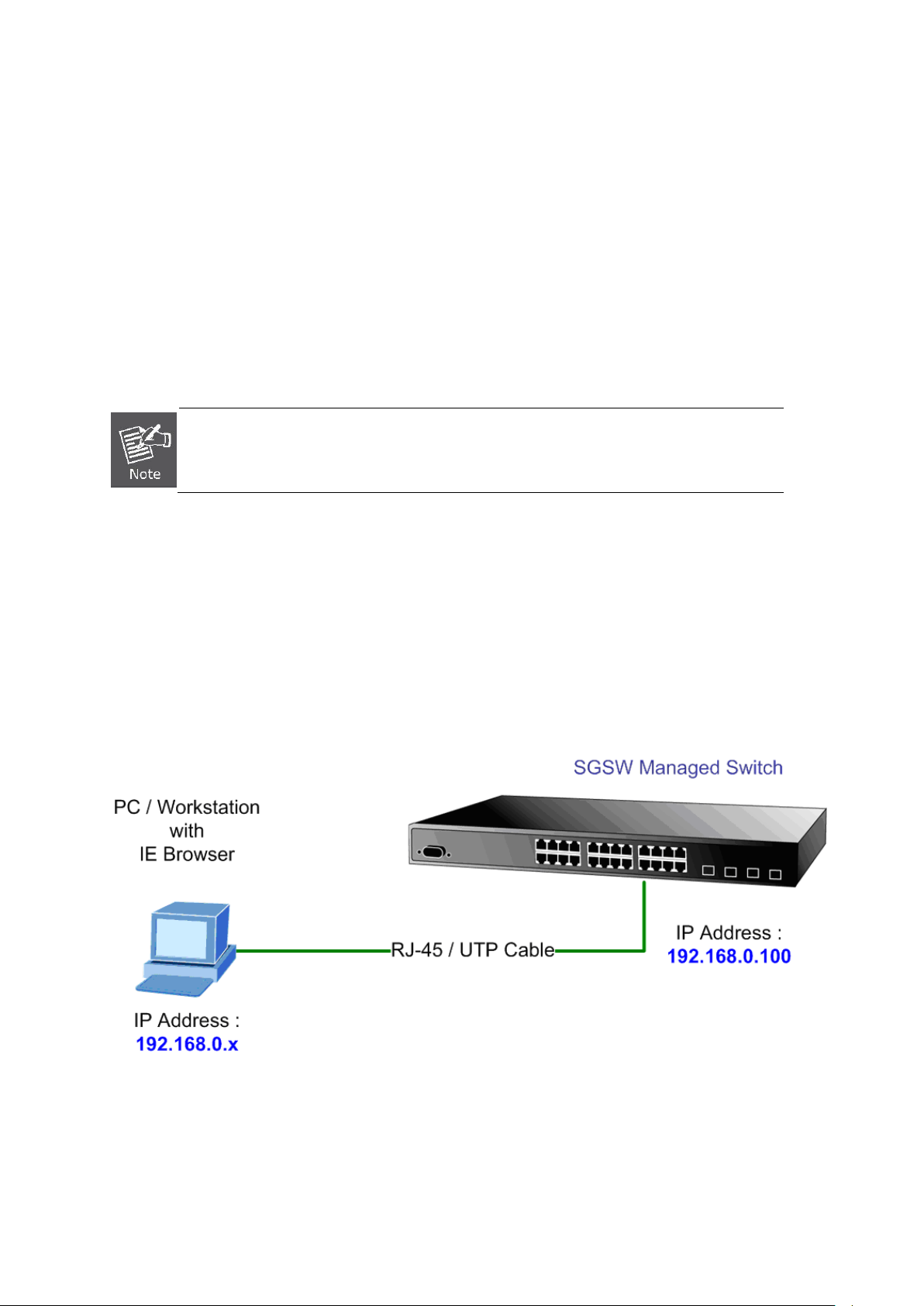
User’s Manual of SGSW-24040 / 24240 Series
58
s to
4. WEB CONFIGURATION
This section introduces the configuration and functions of the Web-Based management.
About Web-based Management
The Managed Switch offers management features that allow users to manage the Managed Switch from anywhere on the
network through a standard browser such as Microsoft Internet Explorer.
The Web-Based Management support s Internet Explorer 7.0. It is based on Java Applets with an aim to reduce network
bandwidth consumption, enhance access speed and present an easy viewing screen.
By default, IE7.0 or later version does not allow Java Applets to open sockets. The user ha
explicitly modify the browser setting to enable Java Applets to use network ports.
The Managed Switch can be configured through an Ethernet connection, make sure the manager PC must be set on same the
IP subnet address with the Managed Switch.
For example, the default IP address of the SGSW Managed Switch is 192.168.0.100, then the manager PC should be set at
192.168.0.x (where x is a number between 1 and 254, except 100), and the default subnet mask is 255.255.255.0.
If you have changed the def aul t IP address of the Managed Switch to 192.168.1.1 w ith s ubn et ma sk 255.255.255.0 via console,
then the manager PC should be set at 192.168.1.x (where x is a number between 2 and 254) to do the relative configuration on
manager PC.
Figure 4-1-1 Web Management
Page 59
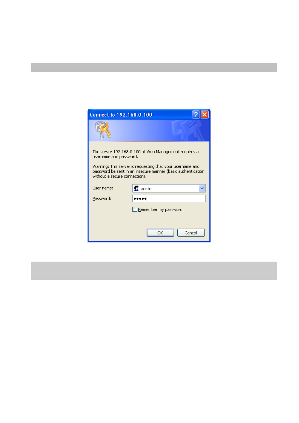
User’s Manual of SGSW-24040 / 24240 Series
59
Logging on the switch
1. Use Internet Explorer 7.0 or above Web browser. Enter the factory-default IP addr es s to ac ces s the Web inter f ace . T he
factory-default IP Address as following:
http://192.168.0.100
2. When the following login screen appears, please enter the default username "admin" with password “admin” (or the
username/password you have changed via console) to login the main screen of Managed Sw itch. T he login scr een in
Figure 4-1-2 appears.
Figure 4-1-2 Login screen
Default User name: admin
Default Password: admin
After entering the username and password, the main screen appears as Figure 4-1-3.
Page 60

User’s Manual of SGSW-24040 / 24240 Series
60
button, you need to
Figure 4-1-3 Default main page
Now, you can use the Web management interface to continue the switch management or manage the Managed Switch by Web
interface. The Switch Menu on the left of the web page let you access all the commands and statistics the Managed Switch
provides.
1. It is recommended to use Internet Explore 7.0 or above to access Managed Switch.
2. The changed IP address take effect immediately after click on the Save
use the new IP address to access the Web interface.
3. For security reason, please change and memorize the new password after this first setup.
4. Only accept command in lowercase letter under web interface.
Page 61

User’s Manual of SGSW-24040 / 24240 Series
61
4.1 Main Web Page
The SGSW Managed Switch provides a Web-based browser interface for configuri ng and m anagi ng it. This interface all ows you
to access the Managed Sw itch using t he Web browser of your choi ce. This chapter describes how to use th e Managed Switch’s
Web browser interface to configure and manage it.
Main Functions Menu
Copper Port Link Status
SFP Port Link Status
Stack Port Link Status
Main Screen
Figure 4-1-4 Main Page
Panel Display
The web agent displays an image of the Managed Switch’s ports. The Mode can be set to display different information for the
ports, i n cluding Link up or Link down. Clicking on the image of a port opens the Port Statistics page.
The port states are illustrated as follows:
Help Button
State Disabled Down Link
RJ-45 Ports
SFP Ports
Stack Ports
Main Menu
Using the onboard web agent, y ou can de fine system parameters, mana ge and control the Managed S witch, and all its ports, or
monitor network conditions. Via the Web-Management, the administrator can setup the Managed Switch by select the functions
those listed in the Main Function. The screen in Figure 4-1-5 appears.
Page 62
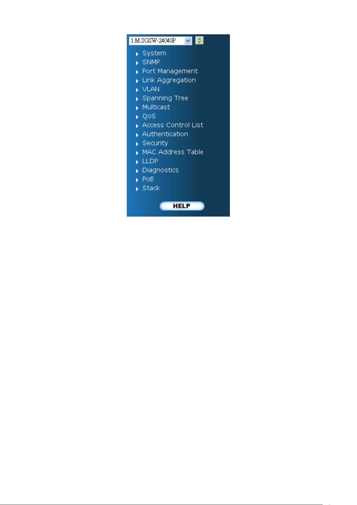
User’s Manual of SGSW-24040 / 24240 Series
62
Figure 4-1-5 SGSW Managed Switch Main Functions Menu
Page 63

User’s Manual of SGSW-24040 / 24240 Series
63
an overview of the current users. Currently the only way
s in XML format
You can load the switch configuration. The configuration f ile i s in XML format
You can restart the stack switch on this page. After restart, the stack switch
4.2 System
Use the System menu items to display and configure basic administrative details of the Managed Switch. Under System the
following topics are provided to configure and view the system information: This section has the following items:
■ System Information The switch system information is provided here.
■ IP Configuration Configure the switch-managed IP information on this page.
■ IPv6 Configuration Configure the switch-managed IPv6 information on this page.
■ Users Configuration
■ Users Privilege Levels
■ NTP Configuration Configure NTP on this page.
■ UPnP Configure UPnP on this page.
■ DHCP Relay Configure DHCP Relay on this page.
■ DHCP Relay Statistics This page provides statistics for DHCP relay.
■ CPU Load This page displays the CPU load, using a SVG graph.
■ System Log The switch system log information is provided here.
■ Detailed Log The switch system detailed log information is provided here.
■ Remote Syslog Configure remote syslog on this page.
■ SMTP Configure Configure SMTP on this page.
■ Web Firmware Upgrade This page facilitates an update of the firmware controlling the switch.
■ TFTP Firmware Upgrade Upgrade the firmware via TFTP server
■ Configuration Backup
This page provides
to login as another user on the web server is to close and reopen the
browser.
This page provides an overview of the privilege levels.
You can save the switch configuration. The c onfigur ation file i
with a hierarchy of tags.
■ Configuration Upload
■ Factory Default
■ System Reboot
with a hierarchy of tags.
You can reset the configuration of the stack switch on this page. Only the IP
configuration is retained.
will boot normally.
 Loading...