

Page 1

1
Page 2

Trademarks
Copyright © PLANET Technology Corp. 2016.
Contents are subject to revision without prior notice.
PLANET is a registered trademark of PLANET Technology Corp. All other trademarks belong to their
respective owners.
Disclaimer
PLANET Technology does not warrant that the hardware will work properly in all environments and
applications, and makes no warranty and representation, either implied or expressed, with respect to the
quality, performance, merchantability, or fitness for a particular purpose. PLANET has made every effort to
ensure that this User's Manual is accurate; PLANET disclaims liability for any inaccuracies or omissions that
may have occurred.
Information in this User's Manual is subject to change without notice and does not represent a commitment on
the part of PLANET. PLANET assumes no responsibility for any inaccuracies that may be contained in this
User's Manual. PLANET makes no commitment to update or keep current the information in this User's
Manual, and reserves the right to make improvements to this User's Manual and/or to the products described
in this User's Manual, at any time without notice.
If you find information in this manual that is incorrect, misleading, or incomplete, we would appreciate your
comments and suggestions.
FCC Warning
This equipment has been tested and found to comply with the limits for a Class A digital device, pursuant to
Part 15 of the FCC Rules. These limits are designed to provide reasonable protection against harmful
interference when the equipment is operated in a commercial environment. This equipment generates, uses,
and can radiate radio frequency energy and, if not installed and used in accordance with the Instruction
manual, may cause harmful interference to radio communications. Operation of this equipment in a residential
area is likely to cause harmful interference in which case the user will be required to correct the interference at
his own expense.
CE Mark Warning
This is a Class A product. In a domestic environment, this product may cause radio interference, in which
case the user may be required to take adequate measures.
Energy Saving Note of the Device
This power required device does not support Standby mode operation. For energy saving, please remove the
power cable to disconnect the device from the power circuit. In view of saving the energy and reducing the
unnecessary power consumption, it is strongly suggested to remove the power connection for the device if
this device is not intended to be active.
WEEE Warning
To avoid the potential effects on the environment and human health as a result of the
presence of hazardous substances in electrical and electronic equipment, end users of
electrical and electronic equipment should understand the meaning of the crossed-out
wheeled bin symbol. Do not dispose of WEEE as unsorted municipal waste and have to
collect such WEEE separately.
Revision
PLANET Layer 3 Multi-Port Full Gigabit Stackable Managed Switch User's Manual
FOR MODEL: SGS-6340-24T4S/48T4S/24P4S/20S4C4X/16XR
REVISION: 1.1 (August, 2016)
Part No: EM-SGS-6340-series
2
Page 3

Contents
CHAPTER 1 INTRODUCTION ........................................................................................ 1-1
1.1 PACKET CONTENTS ............................................................................................................................. 1-1
1.2 PRODUCT DESCRIPTION ....................................................................................................................... 1-2
1.3 PRODUCT FEATURES ........................................................................................................................... 1-6
1.4 PRODUCT SPECIFICATIONS................................................................................................................... 1-9
CHAPTER 2 INSTALLATION............................................................................................17
2.1 HARDWARE DESCRIPTION ..................................................................................................................... 17
2.1.1 Switch Front Panel ................................................................................................................... 17
2.1.2 LED Indications ........................................................................................................................ 19
2.1.3 Switch Rear Panel.................................................................................................................... 24
2.2 INSTALLING THE MANAGED SWITCH....................................................................................................... 26
2.2.1 Desktop Installation.................................................................................................................. 26
2.2.2 Rack Mounting ......................................................................................................................... 27
2.2.3 Installing the SFP/SFP+ Transceiver ....................................................................................... 28
CHAPTER 3 SWITCH MANAGEMENT .......................................................................... 3-1
3.1 MANAGEMENT OPTIONS....................................................................................................................... 3-1
3.1.1 Out-of-Band Management....................................................................................................... 3-1
3.1.2 In-band Management.............................................................................................................. 3-5
3.2 CLI INTERFACE.................................................................................................................................... 3-9
3.2.1 Configuration Modes............................................................................................................. 3-11
3.2.2 Configuration Syntax............................................................................................................. 3-13
3.2.3 Shortcut Key Support ............................................................................................................ 3-14
3.2.4 Help Function ........................................................................................................................ 3-14
3.2.5 Input Verification.................................................................................................................... 3-15
3.2.6 Fuzzy Match Support ............................................................................................................ 3-15
CHAPTER 4 BASIC SWITCH CONFIGURATION .......................................................... 4-1
4.1 BASIC CONFIGURATION........................................................................................................................ 4-1
4.2 TELNET MANAGEMENT......................................................................................................................... 4-2
4.2.1 Telnet....................................................................................................................................... 4-2
4.2.2 SSH ......................................................................................................................................... 4-4
4.3 CONFIGURING SWITCH IP ADDRESSES.................................................................................................. 4-6
4.3.1 Switch IP Addresses Configuration Task List.......................................................................... 4-6
4.4 SNMP CONFIGURATION ....................................................................................................................... 4-7
4.4.1 Introduction to SNMP .............................................................................................................. 4-7
4.4.2 Introduction to MIB .................................................................................................................. 4-9
4.4.3 Introduction to RMON ........................................................................................................... 4-10
4.4.4 SNMP Configuration ............................................................................................................. 4-10
1
Page 4

4.4.5 Typical SNMP Configuration Examples ................................................................................ 4-13
4.4.6 SNMP Troubleshooting ......................................................................................................... 4-15
4.5 SWITCH UPGRADE ............................................................................................................................. 4-15
4.5.1 Switch System Files .............................................................................................................. 4-15
4.5.2 BootROM Upgrade................................................................................................................ 4-16
4.5.3 FTP/TFTP Upgrade............................................................................................................... 4-18
CHAPTER 5 FILE SYSTEM OPERATIONS...................................................................5-28
5.1 INTRODUCTION TO FILE STORAGE DEVICES......................................................................................... 5-28
5.2 FILE SYSTEM OPERATION CONFIGURATION TASK LIST......................................................................... 5-28
5.3 TYPICAL APPLICATIONS...................................................................................................................... 5-30
5.4 TROUBLESHOOTING ........................................................................................................................... 5-30
CHAPTER 6 CLUSTER CONFIGURATION.................................................................... 6-1
6.1 INTRODUCTION TO CLUSTER NETWORK MANAGEMENT............................................................................ 6-1
6.2 CLUSTER NETWORK MANAGEMENT CONFIGURATION SEQUENCE........................................................... 6-1
6.3 EXAMPLES OF CLUSTER ADMINISTRATION ............................................................................................ 6-5
6.4 CLUSTER ADMINISTRATION TROUBLESHOOTING .................................................................................... 6-6
CHAPTER 7 PORT CONFIGURATION........................................................................... 7-7
7.1 INTRODUCTION TO PORT ...................................................................................................................... 7-7
7.2 NETWORK PORT CONFIGURATION TASK LIST ........................................................................................ 7-7
7.3 PORT CONFIGURATION EXAMPLE ....................................................................................................... 7-10
7.4 PORT TROUBLESHOOTING.................................................................................................................. 7-11
CHAPTER 8 PORT ISOLATION FUNCTION CONFIGURATION..................................8-12
8.1 INTRODUCTION TO PORT ISOLATION FUNCTION.................................................................................... 8-12
8.2 TASK SEQUENCE OF PORT ISOLATION................................................................................................. 8-12
8.3 PORT ISOLATION FUNCTION TYPICAL EXAMPLES................................................................................. 8-13
CHAPTER 9 PORT LOOPBACK DETECTION FUNCTION CONFIGURATION ...........9-14
9.1 INTRODUCTION TO PORT LOOPBACK DETECTION FUNCTION ................................................................ 9-14
9.2 PORT LOOPBACK DETECTION FUNCTION CONFIGURATION TASK LIST .................................................. 9-14
9.3 PORT LOOPBACK DETECTION FUNCTION EXAMPLE ............................................................................. 9-16
9.4 PORT LOOPBACK DETECTION TROUBLESHOOTING.............................................................................. 9-17
CHAPTER 10 ULDP FUNCTION CONFIGURATION ..................................................10-18
10.1 INTRODUCTION TO ULDP FUNCTION............................................................................................... 10-18
10.2 ULDP CONFIGURATION TASK SEQUENCE ....................................................................................... 10-19
2
Page 5

10.3 ULDP FUNCTION TYPICAL EXAMPLES............................................................................................ 10-22
10.4 ULDP TROUBLESHOOTING ............................................................................................................ 10-23
CHAPTER 11 LLDP FUNCTION OPERATION CONFIGURATION.............................11-25
11.1 INTRODUCTION TO LLDP FUNCTION ............................................................................................... 11-25
11.2 LLDP FUNCTION CONFIGURATION TASK SEQUENCE ....................................................................... 11-26
11.3 LLDP FUNCTION TYPICAL EXAMPLE............................................................................................... 11-29
11.4 LLDP FUNCTION TROUBLESHOOTING............................................................................................. 11-30
CHAPTER 12 PORT CHANNEL CONFIGURATION ...................................................12-31
12.1 INTRODUCTION TO PORT CHANNEL................................................................................................. 12-31
12.2 BRIEF INTRODUCTION TO LACP..................................................................................................... 12-32
12.2.1 Static LACP Aggregation................................................................................................... 12-33
12.2.2 Dynamic LACP Aggregation.............................................................................................. 12-33
12.2.3 Port Channel Configuration Task List................................................................................ 12-34
12.3 PORT CHANNEL EXAMPLES............................................................................................................ 12-35
12.4 PORT CHANNEL TROUBLESHOOTING .............................................................................................. 12-38
CHAPTER 13 MTU CONFIGURATION ........................................................................13-39
13.1 INTRODUCTION TO MTU ................................................................................................................. 13-39
13.2 MTU CONFIGURATION TASK SEQUENCE ......................................................................................... 13-39
CHAPTER 14 EFM OAM CONFIGURATION...............................................................14-40
14.1 INTRODUCTION TO EFM OAM........................................................................................................ 14-40
14.2 EFM OAM CONFIGURATION .......................................................................................................... 14-43
14.3 EFM OAM EXAMPLE..................................................................................................................... 14-45
14.4 EFM OAM TROUBLESHOOTING ..................................................................................................... 14-46
CHAPTER 15 PORT SECURITY .................................................................................15-48
15.1 INTRODUCTION TO PORT SECURITY............................................................................................ 15-48
15.2 PORT SECURITY CONFIGURATION TASK LIST.............................................................................. 15-48
15.3 EXAMPLE OF PORT SECURITY.................................................................................................... 15-49
15.4 PORT SECURITY TROUBLESHOOTING ......................................................................................... 15-50
CHAPTER 16 DDM CONFIGURATION .......................................................................16-51
16.1 INTRODUCTION TO DDM................................................................................................................. 16-51
16.1.1 Brief Introduction to DDM.................................................................................................. 16-51
16.1.2 DDM Function ................................................................................................................... 16-52
16.2 DDM CONFIGURATION TASK LIST................................................................................................... 16-53
16.3 EXAMPLES OF DDM....................................................................................................................... 16-55
3
Page 6

16.4 DDM TROUBLESHOOTING .............................................................................................................. 16-59
CHAPTER 17 LLDP-MED ............................................................................................17-60
17.1 INTRODUCTION TO LLDP-MED ...................................................................................................... 17-60
17.2 LLDP-MED CONFIGURATION TASK SEQUENCE .............................................................................. 17-60
17.3 LLDP-MED EXAMPLE................................................................................................................... 17-62
17.4 LLDP-MED TROUBLESHOOTING ................................................................................................... 17-65
CHAPTER 18 BPDU-TUNNEL CONFIGURATION ......................................................18-65
18.1 INTRODUCTION TO BPDU-TUNNEL.................................................................................................... 18-65
18.1.1 bpdu-tunnel function.......................................................................................................... 18-66
18.1.2 Background of bpdu-tunnel............................................................................................... 18-66
18.2 BPDU-TUNNEL CONFIGURATION TASK LIST...................................................................................... 18-66
18.3 EXAMPLES OF BPDU-TUNNEL.......................................................................................................... 18-67
18.4 BPDU-TUNNEL TROUBLESHOOTING ................................................................................................. 18-68
CHAPTER 19 EEE ENERGY-SAVING CONFIGURATION ..........................................19-69
19.1 INTRODUCTION TO EEE ENERGY-SAVING ........................................................................................ 19-69
19.2 EEE ENERGY-SAVING CONFIGURATION LIST.................................................................................... 19-69
19.3 EEE ENERGY-SAVING TYPICAL EXAMPLES ..................................................................................... 19-69
CHAPTER 20 VLAN CONFIGURATION ......................................................................20-70
20.1 VLAN CONFIGURATION ................................................................................................................. 20-70
20.1.1 Introduction to VLAN......................................................................................................... 20-70
20.1.2 VLAN Configuration Task List ........................................................................................... 20-71
20.1.3 Typical VLAN Application .................................................................................................. 20-75
20.1.4 Typical Application of Hybrid Port ..................................................................................... 20-77
20.2 DOT1Q-TUNNEL CONFIGURATION ................................................................................................... 20-78
20.2.1 Introduction to Dot1q-tunnel.............................................................................................. 20-78
20.2.2 Dot1q-tunnel Configuration ............................................................................................... 20-80
20.2.3 Typical Applications of the Dot1q-tunnel ........................................................................... 20-80
20.2.4 Dot1q-tunnel Troubleshooting........................................................................................... 20-81
20.3 SELECTIVE Q-IN-Q CONFIGURATION ............................................................................................... 20-82
20.3.1 Introduction to Selective Q-in-Q........................................................................................ 20-82
20.3.2 Selective Q-in-Q Configuration ......................................................................................... 20-82
20.3.3 Typical Applications of Selective Q-in-Q ........................................................................... 20-83
20.3.4 Selective Q-in-Q Troubleshooting ..................................................................................... 20-85
20.4 VLAN TRANSLATION CONFIGURATION............................................................................................ 20-85
20.4.1 Introduction to VLAN Translation ...................................................................................... 20-85
20.4.2 VLAN Translation Configuration........................................................................................ 20-85
20.4.3 Typical Application of VLAN Translation ........................................................................... 20-87
20.4.4 VLAN Translation Troubleshooting ................................................................................... 20-88
4
Page 7

20.5 MULTI-TO-ONE VLAN TRANSLATION CONFIGURATION .................................................................... 20-88
20.5.1 Introduction to Multi-to-One VLAN Translation ................................................................. 20-88
20.5.2 Multi-to-One VLAN Translation Configuration................................................................... 20-88
20.5.3 Typical Application of Multi-to-One VLAN Translation ...................................................... 20-89
20.5.4 Multi-to-One VLAN Translation Troubleshooting .............................................................. 20-90
20.6 DYNAMIC VLAN CONFIGURATION................................................................................................... 20-90
20.6.1 Introduction to Dynamic VLAN.......................................................................................... 20-90
20.6.2 Dynamic VLAN Configuration ........................................................................................... 20-91
20.6.3 Typical Application of the Dynamic VLAN ......................................................................... 20-93
20.6.4 Dynamic VLAN Troubleshooting ....................................................................................... 20-95
20.7 GVRP CONFIGURATION ................................................................................................................. 20-95
20.7.1 Introduction to GVRP ........................................................................................................ 20-95
20.7.2 GVRP Configuration Task List........................................................................................... 20-96
20.7.3 Example of GVRP ............................................................................................................. 20-97
20.7.4 GVRP Troubleshooting ................................................................................................... 20-100
20.8 VOICE VLAN CONFIGURATION ..................................................................................................... 20-100
20.8.1 Introduction to Voice VLAN ............................................................................................. 20-100
20.8.2 Voice VLAN Configuration .............................................................................................. 20-101
20.8.3 Typical Applications of the Voice VLAN .......................................................................... 20-102
20.8.4 Voice VLAN Troubleshooting .......................................................................................... 20-103
CHAPTER 21 MAC TABLE CONFIGURATION .........................................................21-104
21.1 INTRODUCTION TO MAC TABLE .................................................................................................... 21-104
21.1.1 Obtaining MAC Table ...................................................................................................... 21-104
21.1.2 Forward or Filter.............................................................................................................. 21-105
21.2 MAC ADDRESS TABLE CONFIGURATION TASK LIST ........................................................................ 21-106
21.3 TYPICAL CONFIGURATION EXAMPLES ........................................................................................... 21-108
21.4 MAC TABLE TROUBLESHOOTING ................................................................................................. 21-109
21.5 MAC ADDRESS FUNCTION EXTENSION ......................................................................................... 21-109
21.5.1 MAC Address Binding ..................................................................................................... 21-109
21.6 MAC NOTIFICATION CONFIGURATION ............................................................................................21-111
21.6.1 Introduction to MAC Notification ......................................................................................21-111
21.6.2 MAC Notification Configuration........................................................................................21-111
21.6.3 MAC Notification Example .............................................................................................. 21-113
21.6.4 MAC Notification Troubleshooting................................................................................... 21-113
CHAPTER 22 MSTP CONFIGURATION....................................................................22-114
22.1 INTRODUCTION TO MSTP............................................................................................................. 22-114
22.2 MSTP REGION ............................................................................................................................ 22-114
22.2.1 Operations within an MSTP Region................................................................................ 22-115
22.2.2 Port Roles ....................................................................................................................... 22-116
22.2.3 MSTP Load Balance ....................................................................................................... 22-116
5
Page 8

22.3 MSTP CONFIGURATION TASK LIST ............................................................................................... 22-116
22.4 MSTP EXAMPLE.......................................................................................................................... 22-121
22.5 MSTP TROUBLESHOOTING .......................................................................................................... 22-125
CHAPTER 23 QOS CONFIGURATION......................................................................23-126
23.1 INTRODUCTION TO QOS ............................................................................................................... 23-126
23.1.1 QoS Terms ...................................................................................................................... 23-126
23.1.2 QoS Implementation ....................................................................................................... 23-127
23.1.3 Basic QoS Model ............................................................................................................ 23-128
23.2 QOS CONFIGURATION TASK LIST ................................................................................................. 23-131
23.3 QOS EXAMPLE ............................................................................................................................ 23-136
23.4 QOS TROUBLESHOOTING............................................................................................................. 23-138
CHAPTER 24 FLOW-BASED REDIRECTION...............................................................24-1
24.1 INTRODUCTION TO FLOW-BASED REDIRECTION ................................................................................. 24-1
24.2 FLOW-BASED REDIRECTION CONFIGURATION TASK SEQUENCE ......................................................... 24-1
24.3 FLOW-BASED REDIRECTION EXAMPLES ............................................................................................ 24-2
24.4 FLOW-BASED REDIRECTION TROUBLESHOOTING HELP...................................................................... 24-2
CHAPTER 25 FLEXIBLE Q-IN-Q CONFIGURATION ....................................................25-3
25.1 INTRODUCTION TO FLEXIBLE QINQ ................................................................................................... 25-3
25.1.1 Q-in-Q Technique ................................................................................................................ 25-3
25.1.2 Basic Q-in-Q........................................................................................................................ 25-3
25.1.3 Flexible Q-in-Q .................................................................................................................... 25-3
25.1.4 Flexible Q-in-Q Configuration Task List .............................................................................. 25-3
25.2 FLEXIBLE Q-IN-Q EXAMPLE ............................................................................................................. 25-5
25.3 FLEXIBLE Q-IN-Q TROUBLESHOOTING .............................................................................................. 25-7
CHAPTER 26 LAYER 3 MANAGEMENT CONFIGURATION........................................26-7
26.1 LAYER 3 MANAGEMENT INTERFACE .................................................................................................. 26-7
26.1.1 Introduction to Layer 3 Management Interface ................................................................... 26-7
26.1.2 Layer 3 Interface Configuration Task List............................................................................ 26-7
26.2 IP CONFIGURATION.......................................................................................................................... 26-8
26.2.1 Introduction to IPv4, IPv6 .................................................................................................... 26-8
26.2.2 IP Configuration ................................................................................................................ 26-10
26.2.3 IPv6 Troubleshooting ........................................................................................................ 26-12
26.3 STATIC ROUTE............................................................................................................................... 26-12
26.3.1 Introduction to Static Route............................................................................................... 26-12
26.3.2 Introduction to Default Route ............................................................................................ 26-13
26.3.3 Static Route Configuration Task List ................................................................................. 26-13
26.3.4 Static Route Configuration Examples ............................................................................... 26-14
6
Page 9

26.4 RIP............................................................................................................................................... 26-15
26.4.1 Introduction to RIP ............................................................................................................ 26-15
26.4.2 RIP Configuration Task List............................................................................................... 26-17
26.4.3 RIP Examples – Typical RIP ............................................................................................. 26-23
26.4.4 RIP Examples – RIP aggregation function........................................................................ 26-25
26.4.5 RIP Troubleshooting.......................................................................................................... 26-25
26.5 OSPF ........................................................................................................................................... 26-26
26.5.1 Introduction to OSPF......................................................................................................... 26-26
26.5.2 OSPF Configuration Task List........................................................................................... 26-29
26.5.3 OSPF Examples................................................................................................................ 26-34
26.5.4 Configuration Example of OSPF....................................................................................... 26-34
26.5.5 Configuration Examples of OSPF VPN............................................................................. 26-43
26.5.6 OSPF Troubleshooting...................................................................................................... 26-44
26.6 ARP ............................................................................................................................................. 26-45
26.6.1 Introduction to ARP........................................................................................................... 26-45
26.6.2 ARP Configuration Task List.............................................................................................. 26-45
26.6.3 ARP Troubleshooting ........................................................................................................ 26-45
CHAPTER 27 ARP SCANNING PREVENTION FUNCTION CONFIGURATION.........27-46
27.1 INTRODUCTION TO ARP SCANNING PREVENTION FUNCTION ............................................................ 27-46
27.2 ARP SCANNING PREVENTION CONFIGURATION TAS K SEQUENCE .................................................... 27-47
27.3 ARP SCANNING PREVENTION TYPICAL EXAMPLES.......................................................................... 27-49
27.4 ARP SCANNING PREVENTION TROUBLESHOOTING HELP................................................................. 27-50
CHAPTER 28 PREVENT ARP SPOOFING CONFIGURATION ..................................28-51
28.1 OVERVIEW..................................................................................................................................... 28-51
28.1.1 ARP (Address Resolution Protocol) .................................................................................. 28-51
28.1.2 ARP Spoofing .................................................................................................................... 28-51
28.1.3 How to prevent void ARP Spoofing ................................................................................... 28-51
28.2 PREVENT ARP SPOOFING CONFIGURATION..................................................................................... 28-52
28.3 PREVENT ARP SPOOFING EXAMPLE............................................................................................... 28-53
CHAPTER 29 ARP GUARD CONFIGURATION ..........................................................29-55
29.1 INTRODUCTION TO ARP GUARD ................................................................................................... 29-55
29.2 ARP GUARD CONFIGURATION TASK LIST ..................................................................................... 29-56
CHAPTER 30 GRATUITOUS ARP CONFIGURATION ................................................30-57
30.1 INTRODUCTION TO GRATUITOUS ARP ............................................................................................. 30-57
30.2 GRATUITOUS ARP CONFIGURATION TASK LIST ............................................................................... 30-57
30.3 GRATUITOUS ARP CONFIGURATION EXAMPLE ................................................................................ 30-58
30.4 GRATUITOUS ARP TROUBLESHOOTING .......................................................................................... 30-59
7
Page 10

CHAPTER 31 DHCP CONFIGURATION .....................................................................31-60
31.1 INTRODUCTION TO DHCP............................................................................................................... 31-60
31.2 DHCP SERVER CONFIGURATION .................................................................................................... 31-61
31.3 DHCP RELAY CONFIGURATION ...................................................................................................... 31-64
31.4 DHCP CONFIGURATION EXAMPLES................................................................................................ 31-65
31.5 DHCP TROUBLESHOOTING ............................................................................................................ 31-69
CHAPTER 32 DHCPV6 CONFIGURATION .................................................................32-70
32.1 INTRODUCTION TO DHCPV6........................................................................................................... 32-70
32.2 DHCPV6 SERVER CONFIGURATION................................................................................................ 32-71
32.3 DHCPV6 RELAY DELEGATION CONFIGURATION .............................................................................. 32-73
32.4 DHCPV6 PREFIX DELEGATION SERVER CONFIGURATION ................................................................ 32-73
32.5 DHCPV6 PREFIX DELEGATION CLIENT CONFIGURATION ................................................................. 32-75
32.6 DHCPV6 CONFIGURATION EXAMPLES............................................................................................ 32-76
32.7 DHCPV6 TROUBLESHOOTING ........................................................................................................ 32-78
CHAPTER 33 DHCP OPTION 82 CONFIGURATION ..................................................33-80
33.1 INTRODUCTION TO DHCP OPTION 82 ............................................................................................. 33-80
33.1.1 DHCP Option 82 Message Structure ................................................................................ 33-80
33.1.2 Option 82 Working Mechanism......................................................................................... 33-81
33.2 DHCP OPTION 82 CONFIGURATION TASK LIST ............................................................................... 33-82
33.3 DHCP OPTION 82 APPLICATION EXAMPLES ................................................................................... 33-85
33.4 DHCP OPTION 82 TROUBLESHOOTING........................................................................................... 33-87
CHAPTER 34 DHCP OPTION 60 AND OPTION 43 ....................................................34-89
34.1 INTRODUCTION TO DHCP OPTION 60 AND OPTION 43 ..................................................................... 34-89
34.2 DHCP OPTION 60 AND OPTION 43 CONFIGURATION TASK LIST ....................................................... 34-89
34.3 DHCPV6 OPTION 60 AND OPTION 43 EXAMPLE.............................................................................. 34-90
34.4 DHCP OPTION 60 AND OPTION 43 TROUBLESHOOTING .................................................................. 34-90
CHAPTER 35 DHCPV6 OPTIONS 37, 38......................................................................35-1
35.1 INTRODUCTION TO DHCPV6 OPTIONS 37, 38.................................................................................... 35-1
35.2 DHCPV6 OPTIONS 37, 38 CONFIGURATION TASK LIST...................................................................... 35-2
35.3 DHCPV6 OPTIONS 37, 38 EXAMPLES .............................................................................................. 35-8
35.3.1 DHCPv6 Snooping options 37, 38 Example ....................................................................... 35-8
35.3.2 DHCPv6 Relay option37, 38 Example.............................................................................. 35-10
35.4 DHCPV6 OPTIONS 37, 38 TROUBLESHOOTING ............................................................................... 35-11
CHAPTER 36 DHCP SNOOPING CONFIGURATION .................................................36-12
8
Page 11

36.1 INTRODUCTION TO DHCP SNOOPING.............................................................................................. 36-12
36.2 DHCP SNOOPING CONFIGURATION TASK SEQUENCE ...................................................................... 36-13
36.3 DHCP SNOOPING TYPICAL APPLICATION........................................................................................ 36-18
36.4 DHCP SNOOPING TROUBLESHOOTING HELP .................................................................................. 36-19
36.4.1 Monitor and Debug Information ........................................................................................ 36-19
36.4.2 DHCP Snooping Troubleshooting Help............................................................................. 36-19
CHAPTER 37 DHCP SNOOPING OPTION 82 CONFIGURATION..............................37-20
37.1 INTRODUCTION TO DHCP SNOOPING OPTION 82 ............................................................................ 37-20
37.1.1 DHCP Option 82 Message Structure ................................................................................ 37-20
37.1.2 DHCP Snooping Option 82 Working Mechanism ............................................................. 37-21
37.2 DHCP SNOOPING OPTION 82 CONFIGURATION TASK LIST .............................................................. 37-22
37.3 DHCP SNOOPING OPTION 82 APPLICATION EXAMPLES................................................................... 37-23
37.4 DHCP SNOOPING OPTION 82 TROUBLESHOOTING.......................................................................... 37-24
CHAPTER 38 IPV4 MULTICAST PROTOCOL ............................................................38-25
38.1 IPV4 MULTICAST PROTOCOL OVERVIEW......................................................................................... 38-25
38.1.1 Introduction to Multicast .................................................................................................... 38-25
38.1.2 Multicast Address.............................................................................................................. 38-26
38.1.3 IP Multicast Packet Transmission ..................................................................................... 38-27
38.1.4 IP Multicast Application ..................................................................................................... 38-27
38.2 DCSCM........................................................................................................................................ 38-28
38.2.1 Introduction to DCSCM ..................................................................................................... 38-28
38.2.2 DCSCM Configuration Task List........................................................................................ 38-29
38.2.3 DCSCM Configuration Examples...................................................................................... 38-32
38.2.4 DCSCM Troubleshooting .................................................................................................. 38-33
38.3 IGMP SNOOPING........................................................................................................................... 38-33
38.3.1 Introduction to IGMP Snooping......................................................................................... 38-33
38.3.2 IGMP Snooping Configuration Task List ........................................................................... 38-33
38.3.3 IGMP Snooping Examples................................................................................................ 38-36
38.3.4 IGMP Snooping Troubleshooting ...................................................................................... 38-38
CHAPTER 39 IPV6 MULTICAST PROTOCOL ............................................................39-39
39.1 MLD SNOOPING ............................................................................................................................ 39-39
39.1.1 Introduction to MLD Snooping .......................................................................................... 39-39
39.1.2 MLD Snooping Configuration Task ................................................................................... 39-39
39.1.3 MLD Snooping Examples ................................................................................................. 39-41
39.1.4 MLD Snooping Troubleshooting........................................................................................ 39-44
CHAPTER 40 MULTICAST VLAN ...............................................................................40-45
40.1 INTRODUCTIONS TO MULTICAST VLAN........................................................................................... 40-45
40.2 MULTICAST VLAN CONFIGURATION TASK LIST ............................................................................... 40-45
9
Page 12

40.3 MULTICAST VLAN EXAMPLES........................................................................................................ 40-46
CHAPTER 41 ACL CONFIGURATION ........................................................................41-49
41.1 INTRODUCTION TO ACL.................................................................................................................. 41-49
41.1.1 Access-list ......................................................................................................................... 41-49
41.1.2 Access-group .................................................................................................................... 41-49
41.1.3 Access-list Action and Global Default Action..................................................................... 41-49
41.2 ACL CONFIGURATION TASK LIST.................................................................................................... 41-50
41.3 ACL EXAMPLE .............................................................................................................................. 41-64
41.4 ACL TROUBLESHOOTING............................................................................................................... 41-69
CHAPTER 42 802.1X CONFIGURATION ....................................................................42-71
42.1 INTRODUCTION TO 802.1X .............................................................................................................. 42-71
42.1.1 The Authentication Structure of 802.1x ............................................................................. 42-71
42.1.2 The Work Mechanism of 802.1x ....................................................................................... 42-73
42.1.3 The Encapsulation of EAPOL Messages .......................................................................... 42-74
42.1.4 The Encapsulation of EAP Attributes ................................................................................ 42-75
42.1.5 The Authentication Methods of 802.1x.............................................................................. 42-77
42.1.6 The Extension and Optimization of 802.1x ....................................................................... 42-81
42.1.7 The Features of VLAN Allocation...................................................................................... 42-82
42.2 802.1X CONFIGURATION TASK LIST ................................................................................................ 42-83
42.3 802.1X APPLICATION EXAMPLE...................................................................................................... 42-87
42.3.1 Examples of Guest VLAN Applications ............................................................................. 42-87
42.3.2 Examples of IPv4 RADIUS Applications ........................................................................... 42-90
42.3.3 Examples of IPv6 RADIUS Application............................................................................. 42-91
42.4 802.1X TROUBLESHOOTING ........................................................................................................... 42-92
CHAPTER 43 THE NUMBER LIMITATION FUNCTION OF MAC AND IP IN PORT, VLAN
CONFIGURATION ........................................................................................................43-93
43.1 THE NUMBER LIMITATION FUNCTION OF MAC AND IP IN PORT, VLAN CONFIGURATION TASK SEQUENCE
............................................................................................................................................................. 43-94
43.2 THE NUMBER LIMITATION FUNCTION OF MAC AND IP IN PORT, VLAN TYPICAL EXAMPLES............... 43-97
43.3 THE NUMBER LIMITATION FUNCTION OF MAC AND IP IN PORT, VLAN TROUBLESHOOTING HELP...... 43-98
CHAPTER 44 OPERATIONAL CONFIGURATION OF AM FUNCTION ......................44-99
44.1 INTRODUCTION TO AM FUNCTION ................................................................................................... 44-99
44.2 AM FUNCTION CONFIGURATION TASK LIST ..................................................................................... 44-99
44.3 AM FUNCTION EXAMPLE.............................................................................................................. 44-101
44.4 AM FUNCTION TROUBLESHOOTING .............................................................................................. 44-102
CHAPTER 45 SECURITY FEATURE CONFIGURATION..........................................45-103
45.1 INTRODUCTION TO SECURITY FEATURE ......................................................................................... 45-103
10
Page 13

45.2 SECURITY FEATURE CONFIGURATION ........................................................................................... 45-103
45.2.1 Prevent IP Spoofing Function Configuration Task Sequence .........................................45-103
45.2.2 Prevent TCP Unauthorized Label Attack Function Configuration Task Sequence ......... 45-103
45.2.3 Anti Port Cheat Function Configuration Task Sequence................................................. 45-104
45.2.4 Prevent TCP Fragment Attack Function Configuration Task Sequence ......................... 45-104
45.2.5 Prevent ICMP Fragment Attack Function Configuration Task Sequence ....................... 45-104
45.3 SECURITY FEATURE EXAMPLE...................................................................................................... 45-105
CHAPTER 46 TACACS+ CONFIGURATION.............................................................46-106
46.1 INTRODUCTION TO TACACS+...................................................................................................... 46-106
46.2 TACACS+ CONFIGURATION TASK LIST ........................................................................................ 46-106
46.3 TACACS+ SCENARIOS TYPICAL EXAMPLES................................................................................. 46-107
46.4 TACACS+ TROUBLESHOOTING ................................................................................................... 46-108
CHAPTER 47 RADIUS CONFIGURATION................................................................47-109
47.1 INTRODUCTION TO RADIUS......................................................................................................... 47-109
47.1.1 AAA and RADIUS Introduction ........................................................................................ 47-109
47.1.2 Message Structure for RADIUS ...................................................................................... 47-109
47.2 RADIUS CONFIGURATION TASK LIST ............................................................................................47-111
47.3 RADIUS TYPICAL EXAMPLES ...................................................................................................... 47-113
47.3.1 IPv4 RADIUS Example ................................................................................................... 47-113
47.3.2 IPv6 RADIUS Example ................................................................................................... 47-114
47.4 RADIUS TROUBLESHOOTING ...................................................................................................... 47-114
CHAPTER 48 SSL CONFIGURATION.......................................................................48-116
48.1 INTRODUCTION TO SSL................................................................................................................ 48-116
48.1.1 Basic Element of SSL ..................................................................................................... 48-117
48.2 SSL CONFIGURATION TASK LIST .................................................................................................. 48-118
48.3 SSL TYPICAL EXAMPLE............................................................................................................... 48-119
48.4 SSL TROUBLESHOOTING ............................................................................................................. 48-119
CHAPTER 49 IPV6 SECURITY RA CONFIGURATION.............................................49-121
49.1 INTRODUCTION TO IPV6 SECURITY RA.......................................................................................... 49-121
49.2 IPV6 SECURITY RA CONFIGURATION TASK SEQUENCE.................................................................. 49-121
49.3 IPV6 SECURITY RA TYPICAL EXAMPLES....................................................................................... 49-122
49.4 IPV6 SECURITY RA TROUBLESHOOTING HELP .............................................................................. 49-123
CHAPTER 50 MAB CONFIGURATION .....................................................................50-124
50.1 INTRODUCTION TO MAB............................................................................................................... 50-124
50.2 MAB CONFIGURATION TASK LIST................................................................................................. 50-124
11
Page 14

50.3 MAB EXAMPLE ........................................................................................................................... 50-126
50.4 MAB TROUBLESHOOTING ............................................................................................................ 50-128
CHAPTER 51 PPPOE INTERMEDIATE AGENT CONFIGURATION ........................51-129
51.1 INTRODUCTION TO PPPOE INTERMEDIATE AGENT ......................................................................... 51-129
51.1.1 Brief Introduction to PPPoE ............................................................................................ 51-129
51.1.2 Introduction to PPPoE IA ................................................................................................ 51-129
51.2 PPPOE INTERMEDIATE AGENT CONFIGURATION TASK LIST ........................................................... 51-134
51.3 PPPOE INTERMEDIATE AGENT TYPICAL APPLICATION................................................................... 51-135
51.4 PPPOE INTERMEDIATE AGENT TROUBLESHOOTING ...................................................................... 51-137
CHAPTER 52 WEB PORTAL CONFIGURATION ......................................................52-138
52.1 INTRODUCTION TO WEB PORTAL AUTHENTICATION........................................................................ 52-138
52.2 WEB PORTAL AUTHENTICATION CONFIGURATION TASK LIST.......................................................... 52-138
52.3 WEB PORTAL AUTHENTICATION TYPICAL EXAMPLE....................................................................... 52-140
52.4 WEB PORTAL AUTHENTICATION TROUBLESHOOTING ..................................................................... 52-141
CHAPTER 53 VLAN-ACL CONFIGURATION ...............................................................53-1
53.1 INTRODUCTION TO VLAN-ACL ........................................................................................................ 53-1
53.2 VLAN-ACL CONFIGURATION TASK LIST .......................................................................................... 53-1
53.3 VLAN-ACL CONFIGURATION EXAMPLE............................................................................................ 53-3
53.4 VLAN-ACL TROUBLESHOOTING...................................................................................................... 53-4
CHAPTER 54 SAVI CONFIGURATION .........................................................................54-5
54.1 INTRODUCTION TO SAVI................................................................................................................... 54-5
54.2 SAVI CONFIGURATION ..................................................................................................................... 54-5
54.3 SAVI TYPICAL APPLICATION .......................................................................................................... 54-10
54.4 SAVI TROUBLESHOOTING .............................................................................................................. 54-11
CHAPTER 55 MRPP CONFIGURATION .....................................................................55-12
55.1 INTRODUCTION TO MRPP .............................................................................................................. 55-12
55.1.1 Conception Introduction .................................................................................................... 55-12
55.1.2 MRPP Protocol Packet Types ........................................................................................... 55-13
55.1.3 MRPP Protocol Operation System.................................................................................... 55-14
55.2 MRPP CONFIGURATION TASK LIST ................................................................................................ 55-14
55.3 MRPP TYPICAL SCENARIO ............................................................................................................ 55-16
55.4 MRPP TROUBLESHOOTING............................................................................................................ 55-18
CHAPTER 56 ULPP CONFIGURATION ......................................................................56-20
56.1 INTRODUCTION TO ULPP ............................................................................................................... 56-20
12
Page 15

56.2 ULPP CONFIGURATION TASK LIST ................................................................................................. 56-21
56.3 ULPP TYPICAL EXAMPLES ............................................................................................................ 56-24
56.3.1 ULPP Typical Example1.................................................................................................... 56-24
56.3.2 ULPP Typical Example2.................................................................................................... 56-26
56.4 ULPP TROUBLESHOOTING............................................................................................................. 56-27
CHAPTER 57 ULSM CONFIGURATION .....................................................................57-28
57.1 INTRODUCTION TO ULSM............................................................................................................... 57-28
57.2 ULSM CONFIGURATION TASK LIST................................................................................................. 57-29
57.3 ULSM TYPICAL EXAMPLE.............................................................................................................. 57-30
57.4 ULSM TROUBLESHOOTING ............................................................................................................ 57-31
CHAPTER 58 MIRROR CONFIGURATION .................................................................58-32
58.1 INTRODUCTION TO MIRROR............................................................................................................. 58-32
58.2 MIRROR CONFIGURATION TASK LIST............................................................................................... 58-32
58.3 MIRROR EXAMPLES ....................................................................................................................... 58-33
58.4 DEVICE MIRROR TROUBLESHOOTING.............................................................................................. 58-34
CHAPTER 59 SFLOW CONFIGURATION...................................................................59-35
59.1 INTRODUCTION TO SFLOW .............................................................................................................. 59-35
59.2 SFLOW CONFIGURATION TASK LIST ................................................................................................ 59-35
59.3 SFLOW EXAMPLES......................................................................................................................... 59-37
59.4 SFLOW TROUBLESHOOTING ........................................................................................................... 59-38
CHAPTER 60 RSPAN CONFIGURATION ...................................................................60-39
60.1 INTRODUCTION TO RSPAN ............................................................................................................ 60-39
60.2 RSPAN CONFIGURATION TASK LIST .............................................................................................. 60-41
60.3 TYPICAL EXAMPLES OF RSPAN ..................................................................................................... 60-42
60.4 RSPAN TROUBLESHOOTING.......................................................................................................... 60-45
CHAPTER 61 ERSPAN ................................................................................................61-46
61.1 INTRODUCTION TO ERSPAN .......................................................................................................... 61-46
61.2 ERSPAN CONFIGURATION TASK LIST ............................................................................................ 61-46
61.3 TYPICAL EXAMPLES OF ERSPAN .................................................................................................. 61-47
61.4 ERSPAN TROUBLESHOOTING ....................................................................................................... 61-49
CHAPTER 62 SNTP CONFIGURATION ......................................................................62-50
62.1 INTRODUCTION TO SNTP ............................................................................................................... 62-50
62.2 TYPICAL EXAMPLES OF SNTP CONFIGURATION .............................................................................. 62-51
13
Page 16

CHAPTER 63 NTP FUNCTION CONFIGURATION .....................................................63-52
63.1 INTRODUCTION TO NTP FUNCTION ................................................................................................. 63-52
63.2 NTP FUNCTION CONFIGURATION TASK LIST.................................................................................... 63-52
63.3 TYPICAL EXAMPLES OF NTP FUNCTION.......................................................................................... 63-55
63.4 NTP FUNCTION TROUBLESHOOTING............................................................................................... 63-55
CHAPTER 64 SUMMER TIME CONFIGURATION ......................................................64-56
64.1 INTRODUCTION TO SUMMER TIME ................................................................................................... 64-56
64.2 SUMMER TIME CONFIGURATION TASK SEQUENCE ........................................................................... 64-56
64.3 EXAMPLES OF SUMMER TIME ......................................................................................................... 64-57
64.4 SUMMER TIME TROUBLESHOOTING................................................................................................. 64-57
CHAPTER 65 DNSV4/V6 CONFIGURATION ..............................................................65-58
65.1 INTRODUCTION TO DNS ................................................................................................................. 65-58
65.2 DNSV4/V6 CONFIGURATION TASK LIST .......................................................................................... 65-59
65.3 TYPICAL EXAMPLES OF DNS.......................................................................................................... 65-61
65.4 DNS TROUBLESHOOTING............................................................................................................... 65-63
CHAPTER 66 MONITOR AND DEBUG .......................................................................66-64
66.1 PING ............................................................................................................................................. 66-64
66.2 PING6 ........................................................................................................................................... 66-64
66.3 TRACEROUTE ................................................................................................................................ 66-64
66.4 TRACEROUTE6 .............................................................................................................................. 66-65
66.5 SHOW ........................................................................................................................................... 66-65
66.6 DEBUG .......................................................................................................................................... 66-66
66.7 SYSTEM LOG ................................................................................................................................. 66-66
66.7.1 System Log Introduction ................................................................................................... 66-66
66.7.2 System Log Configuration................................................................................................. 66-69
66.7.3 System Log Configuration Example.................................................................................. 66-70
CHAPTER 67 RELOAD SWITCH AFTER SPECIFIED TIME ......................................67-71
67.1 INTRODUCTION TO RELOAD SWITCH AFTER SPECIFIED TIME ............................................................ 67-71
67.2 RELOAD SWITCH AFTER SPECIFIED TIME TASK LIST ........................................................................ 67-71
CHAPTER 68 DEBUGGING AND DIAGNOSIS FOR PACKETS RECEIVED AND SENT
BY CPU ........................................................................................................................68-72
68.1 INTRODUCTION TO DEBUGGING AND DIAGNOSIS FOR PACKETS RECEIVED AND SENT BY CPU........... 68-72
68.2 DEBUGGING AND DIAGNOSIS FOR PACKETS RECEIVED AND SENT BY CPU TASK LIST ...................... 68-72
14
Page 17

CHAPTER 69 DYING GASP CONFIGURATION .........................................................69-73
69.1 INTRODUCTION TO DYING GASP...................................................................................................... 69-73
69.2 DYING GASP TYPICAL EXAMPLES................................................................................................... 69-73
69.3 DYING GASP TROUBLESHOOTING ................................................................................................... 69-73
CHAPTER 70 POE CONFIGURATION ........................................................................70-74
70.1 INTRODUCTION TO POE.................................................................................................................. 70-74
70.2 POE CONFIGURATION .................................................................................................................... 70-74
70.3 TYPICAL APPLICATION OF POE....................................................................................................... 70-76
70.4 POE TROUBLESHOOTING HELP ...................................................................................................... 70-77
15
Page 18

User’s Manual of SGS-6340 seriesT
Chapter 1 INTRODUCTION
Thank you for purchasing PLANET L3 Multi-Port Full Gigabit Stackable Managed Switch,
SGS-6340-24T4S/SGS-6340-24P4S/SGS-6340-20S4C4X/SGS-6340-48T4S/SGS-6340-16XR. The
descriptions of these models are as follows:
SGS-6340-24T4S
SGS-6340-24P4S
SGS-6340-20S4C4X
SGS-6340-48T4S
SGS-6340-16XR
The term “Managed Switch” means the Switches mentioned in this user’s manual.
Layer 3 24-Port 10/100/1000T + 4-Port 1000X SFP Stackable Managed Switch
Layer 3 24-Port 10/100/1000T 802.3at PoE + 4-Port 1000X SFP Stackable Managed Switch
(370W)
Layer 3 20-Port 100/1000X SFP + 4-Port Gigabit TP/SFP + 4-Port 10G SFP+ Stackable
Managed Switch
Layer 3 48-Port 10/100/1000T + 4-Port 1000X SFP Stackable Managed Switch
Layer 3 16-Port 10GBASE-SR/LR SFP+ Stackable Managed Switch (100~240V AC, -48~-60V
DC)
1.1 Packet Contents
Open the box of the Managed Switch and carefully unpack it. The box should contain the following items:
The Managed Switch
Quick Installation Guide
Power Cord
RJ45-to-DB9 Console Cable
Rubber Feet
Two Rack-mounting Brackets with Attachment
Screws
SFP Dust Caps (Please refer to table below)
x 1
x 1
x 1
x 1
x 4
x 1
SFP Dust Cap Model Name
4 SGS-6340-24T4S/24P4S/48T4S
16 SGS-6340-16XR
28 SGS-6340-20S4C4X
If any of these are missing or damaged, please contact your dealer immediately; if possible, retain the carton
including the original packing material, and use them again to repack the product in case there is a need to
return it to us for repair.
1-1
Page 19
User’s Manual of SGS-6340 seriesT
1.2 Product Description
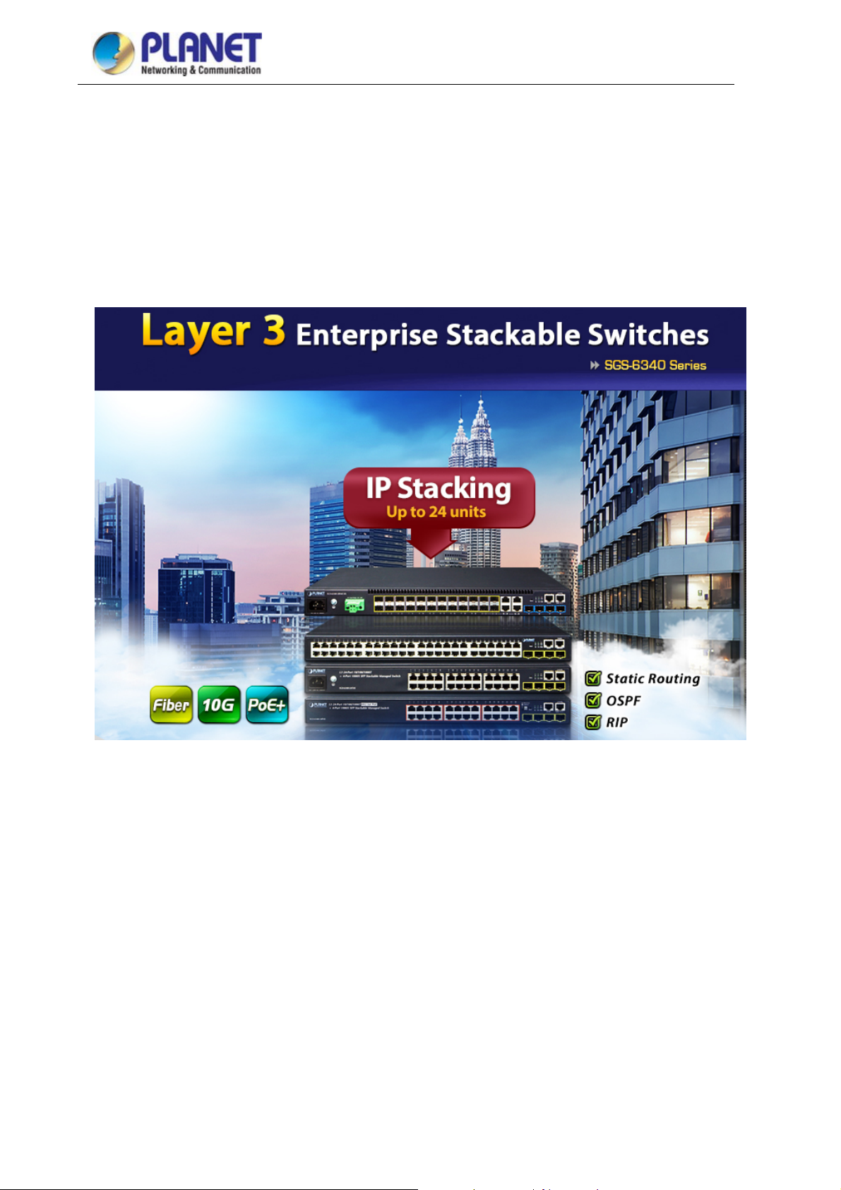
Cost-effective Layer 3 Routing Solution for Enterprise Intranet Networking
Designed for enterprises and small- and medium-sized businesses where an intranet routing network is built,
PLANET SGS-6340 Series, a Layer 3 Stackable Gigabit Managed Switch, provides hardware-based Layer 3
routing capability with IPv4/IPv6 static routing, RIP (Routing Information Protocol) and OSPF (Open
Shortest Path First) routing features which allow to crossover different VLANs and different IP addresses,
and performs effective data traffic control for security, VoIP and video streaming applications.
Efficient IP Stacking Management
The SGS-6340 Series supports IP stacking function that helps network managers to easily configure up to 24
switches in the same series via one single IP address instead of connecting and setting each unit one by one.
It enables centralized management regardless of the series of switches being distributed in various locations.
New switches can be flexibly added to the IP stacking group when network expands.
Layer 3 Routing Support
The SGS-6340 Series enables the administrator to conveniently boost network efficiency by configuring Layer
3 static routing manually, the RIP (Routing Information Protocol) or OSPF (Open Shortest Path First) settings
automatically. The RIP can employ the hop count as a routing metric and prevent routing loops by
implementing a limit on the number of hops allowed in a path from the source to a destination. The maximum
number of hops allowed for the RIP is 15. The OSPF is an interior dynamic routing protocol for autonomous
system based on link-state. The protocol creates a link-state database by exchanging link-states among
Layer 3 switches, and then uses the Shortest Path First algorithm to generate a route table based on that
database.
1-2
Page 20
User’s Manual of SGS-6340 seriesT
Abundant IPv6 Support
The SGS-63
40 Series provides IPv6 management and enterprise-level secure features such as SSH,
ACL, WRR and RADIUS authentication. The SGS-6340 Series thus helps the enterprises to step in the IPv6
era with the lowest investment. In addition, you don’t need to replace the network facilities when the IPv6
FTTx edge network is built.
High Performance
The SGS-6340 Series boasts a high-performance switch architecture that is capable of providing
non-blocking switch fabric and wire-speed throughput as high as 56~128Gbps, which greatly simplifies the
tasks of upgrading the LAN for catering to increasing bandwidth demands.
Robust Layer 2 Features
The SGS-6340 Series can be programmed for basic switch management functions such as port speed
configuration, port aggregation, VLAN, Spanning Tree Protocol, WRR, bandwidth control and IGMP snooping.
The SGS-6340 Series provides 802.1Q tagged VLAN, Q-in-Q, voice VLAN and GVRP Protocol. The VLAN
groups allowed to be on the SGS-6340 Series will be maximally up to 256. By supporting port aggregation,
the SGS-6340 Series allows the operation of a high-speed trunk combined with multiple ports. It enables up to
128 groups for trunking with a maximum of 8 ports for each group.
Excellent Traffic Con
trol
The SGS-6340 Series is loaded with powerful traffic management and WRR features to enhance services
offered by telecoms. The WRR functionalities include wire-speed Layer 4 traffic classifiers and bandwidth
limitation which are particularly useful for multi-tenant unit, multi-business unit, Telco, or network service
applications. It also empowers the enterprises to take full advantage of the limited network resources and
guarantees the best in VoIP and video conferencing transmission.
Powerful Security
The SGS-6340 Series supports ACL policies comprehensively. The traffic can be classified by
source/destination IP addresses, source/destination MAC addresses, IP protocols, TCP/UDP, IP precedence,
time ranges and ToS. Moreover, various policies can be conducted to forward the traffic. The SGS-6340
Series also provides IEEE 802.1x port based access authentication, which can be deployed with RADIUS, to
ensure the port level security and block illegal users.
Efficient Management
For efficient management, the SGS-6340 Series Managed Gigabit Switch is equipped with console, Web and
SNMP management interfaces. With its built-in Web-based management interface, the SGS-6340 Series
offers an easy-to-use, platform-independent management and configuration facility. The SGS-6340 Series
supports standard Simple Network Management Protocol (SNMP) and can be managed via any
1-3
Page 21

User’s Manual of SGS-6340 seriesT
standard-based managem
ent software. For text-based management, the SGS-6340 Series can be accessed
via Telnet and the console port. Moreover, the SGS-6340 Series offers secure remote management by
supporting SSH connection which encrypts the packet content at each session.
Flexibility and Extension Solution
The SGS-6340-20S4C4X provides twenty-four 100/1000Mbps dual speed SFP Fiber ports, four 1/10Gbps
SFP+ Fiber ports, and four 10/100/1000Mbps TP/SFP combo ports. Each of the SFP+ slots
supports Dual-Speed, 10GBASE-SR/LR or 1000BASE-SX/LX. Therefore, the administrator can flexibly
choose the suitable SFP transceiver according to not only the transmission distance, but also the
transmission speed required. The four mini-GBIC slots built in the SGS-6340-24T4S/48T4S/24P4S are
compatible with 1000BASE-X and WDM SFP (Small Form-factor Pluggable) fiber-optic modules. The
distance can be extended from 550 meters (multi-mode fiber) to 10/50/70/120 kilometers (single-mode fiber or
WDM fiber). They are well suited for applications within the enterprise data centers and distributions.
AC and DC Redundant Power to Ensure Continuous Operation (SGS-6340-20S4C4X only)
The SGS-6340-20S4C4X is equipped with one 100~240V AC power supply unit and one additional -48 ~
-60V DC power supply unit for redundant power supply installation. A redundant power system is also
provided to enhance the reliability with either AC or DC power supply unit. The redundant power system is
specifically designed to handle the demands of high-tech facilities requiring the highest power integrity.
Furthermore, with the -48 ~ -60V DC power supply implemented, the SGS-6340-20S4C4X can be applied as
the telecom level device.
Centralized Power Management for Gigabit Ethernet PoE Networking (SGS-6340-24P4S only)
To fulfill the needs of higher power required PoE network applications with Gigabit speed transmission, the
SGS-6340-24P4S features high-performance Gigabit IEEE 802.3af PoE (up to 15.4 watts) and IEEE 802.3at
PoE+ (up to 30 watts) on all ports. It perfectly meets the power requirement of PoE VoIP phone and all kinds
of PoE IP cameras such as IR, PTZ, speed dome cameras or even box type IP cameras with built-in fan and
heater.
1-4
Page 22

User’s Manual of SGS-6340 seriesT
The SGS-6340-24P4S’s PoE capabilities al
so help to reduce deployment costs for network devices as a
result of freeing from restrictions of power outlet locations. Power and data switching are integrated into one
unit, delivered over a single cable and managed centrally. It thus eliminates cost for additional AC wiring and
reduces installation time.
PoE Schedule for Energy Saving (SGS-6340-24P4S only)
Besides being used for IP surveillance, the SGS-6340-24P4S is certainly applicable to building any PoE
network including VoIP and wireless LAN. Under the trend of energy saving worldwide and contributing to the
environmental protection on the Earth, the SGS-6340-24P4S can effectively control the power supply besides
its capability of giving high watts power. The “PoE schedule” function helps you to enable or disable PoE
power feeding for each PoE port during specified time intervals and it is a powerful function to help SMBs or
enterprises save energy and budget
1-5
Page 23

User’s Manual of SGS-6340 seriesT
1.3 Product Features
Physical Ports
4/24/48-Port 10/100/1000BASE-T Gigabit Ethernet RJ45
4/24 1000BASE-X mini-GBIC/SFP slots, SFP type auto detection (only SGS-6340-20S4C4X
supports 100BASE-FX SFP)
4 10GBASE-SR/LR SFP+
only)
16 10GBASE-SR/LR SFP+
only)
RJ45 to DB9 console interface for switch basic management and setup
Power over Ethernet (SGS-6340-24P4S only)
Complies with IEEE 802.3at Power over Ethernet Plus, end-span PSE
Backward compatible with IEEE 802.3af Power over Ethernet
Up to 24 ports of IEEE 802.3af/802.3at devices powered
Supports PoE power up to 30 watts for each PoE port
Auto detects powered device (PD)
Circuit protection prevents power interference between ports
Remote power feeding up to 100 meters
PoE management
- Total PoE power budget control
- Per port PoE function enable/disable
- PoE port power feeding priority
- Per PoE port power limitation
- PD classification detection
- PoE schedule
IP Stacking
Connects with stack member via both Gigabit TP and SFP interfaces
Single IP address management, supporting up to 24 units stacked together
IP Routing Features
Supports maximum 128 static routes and route summarization
Supports dynamic routing protocol: RIP and OSPF
Layer 2 Features
Complies with the IEEE 802.3, IEEE 802.3u, IEEE 802.3ab, IEEE 802.3z Gigabit Ethernet standard
Supports auto-negotiation and half-duplex/full-duplex modes for all 10BASE-T, 100BASE-TX and
1000BASE-T ports
Auto-MDI/MDI-X detection on each RJ45 port
Prevents packet loss flow control
- IEEE 802.3x pause frame flow control in full-duplex mode
- Back-pressure flow control in half-duplex mode
High performance Store-and-Forward architecture, broadcast storm control, port loopback detect
slots, compatible with 1000BASE-SX/LX/BX SFP (SGS-6340-20S4C4X
slots, compatible with 1000BASE-SX/LX/BX SFP (SGS-6340-16XR
1-6
Page 24

User’s Manual of SGS-6340 seriesT
16K MAC addre
ss table, automatic source address learning and aging
Supports VLAN
- IEEE 802.1Q tag-based VLAN
- GVRP for dynamic VLAN management
- Up to 256 VLANs groups, out of 4041 VLAN IDs
- Provider Bridging (VLAN Q-in-Q, IEEE 802.1ad) supported
- Private VLAN Edge (PVE) supported
- GVRP protocol for Management VLAN
- Protocol-based VLAN
- MAC-based VLAN
- IP subnet VLAN
Supports Link Aggregation
- Maximum 128 trunk groups, up to 8 ports per trunk group
- IEEE 802.3ad LACP (Link Aggregation Control Protocol)
- Cisco ether-channel (static trunk)
Supports Spanning Tree Protocol
- STP, IEEE 802.1D (Classic Spanning Tree Protocol)
- RSTP, IEEE 802.1w (Rapid Spanning Tree Protocol)
- MSTP, IEEE 802.1s (Multiple Spanning Tree Protocol, spanning tree by VLAN)
- Supports BPDU & root guard
Port mirroring to monitor the incoming or outgoing traffic on a particular port (many to many)
Provides port mirror (many-to-1)
Quality of Service
8 priority queues on all switch ports
Support for strict priority and WRR (Weighted Round Robin) CoS policies
Traffic classification
- IEEE 802.1p CoS/ToS
- IPv4/IPv6 DSCP
- Port-based WRR
Strict priority and WRR CoS policies
Multicast
Supports IPv4 IGMP snooping v1, v2 and v3, IPv6 MLD v1 and v2 snooping
Querier mode support
Supports Multicast VLAN Register (MVR)
Security
IEEE 802.1x port-based network access authentication
MAC-based network access authentication
Built-in RADIUS client to co-operate with the RADIUS servers for IPv4 and IPv6
TACACS+ login users access authentication
IP-based Access Control List (ACL)
MAC-based Access Control List
Supports DHCP snooping
1-7
Page 25

User’s Manual of SGS-6340 seriesT
Supports
ARP inspection
IP Source Guard prevents IP spoofing attacks
Dynamic ARP Inspection discards ARP packets with invalid MAC address to IP address binding
Management
Management IP for IPv4 and IPv6
Switch Management Interface
- Console/Telnet Command Line Interface
- Web switch management
- SNMP v1, v2c, and v3 switch management
- SSH/SSL secure access
BOOTP and DHCP for IP address assignment
Firmware upload/download via TFTP or HTTP Protocol for IPv4 and IPv6
SNTP (Simple Network Time Protocol) for IPv4 and IPv6
User privilege levels control
Syslog server for IPv4 and IPv6
Four RMON groups 1, 2, 3, 9 (history, statistics, alarms and events)
Supports ping, trace route function for IPv4 and IPv6
1-8
Page 26

1.4 Product Specifications
User’s Manual of SGS-6340 seriesT
Product
Hardware Specifications
Copper Ports
PoE Injector Port
SFP/mini-GBIC Slots
Console
Switch Architecture
Switch Fabric
Switch Throughput
Address Table
Shared Data Buffer
Flow Control
SGS-6340-24T4S SGS-6340-24P4S SGS-6340-48T4S
24 10/100/1000BASE-T
RJ45 auto-MDI/MDI-X
ports
-
4 1000BASE-X SFP interfaces
1 x RJ45-to-RS232 serial port (9600, 8, N, 1)
Store-and-forward
56Gbps/non-blocking 56Gbps/non-blocking 104Gbps/non-blocking
41.66Mpps 41.66Mpps 77.38Mpps
16K MAC address table with auto learning function
1.5MB
Back pressure for half-duplex
IEEE 802.3x pause frame for full-duplex
24 10/100/1000BASE-T
RJ45 auto-MDI/MDI-X
ports
24 ports with 802.3at/af
PoE injector function
48 10/100/1000BASE-T
RJ45 auto-MDI/MDI-X
ports
-
Jumbo Frame
Dimensions (W x D x H)
Weight
Power Consumption
Power Requirements
Power over Ethernet
PoE Standard
PoE Power Supply Type
PoE Power Output
Power Pin Assignment
PoE Power Budget
PoE Ability PD @ 9 watts
9KB
442 x 220 x 44 mm, 1U
height
2340g 4503g 3702g
19.2 watts/65.51 BTU
(maximum)
AC 100~240V, 50/60Hz
-- IEEE 802.3at PoE+ PSE --
-- End-span --
-- Per port 54V DC, 33
-- 1/2(+), 3/6(-) --
-- 370 watts (max.) --
-- 24 units --
442 x 330 x 44 mm, 1U
height
449 watts/1532.05 BTU
(maximum)
watts (max.)
442 x 280 x 44 mm, 1U
height
38 watts/129 BTU
(maximum)
--
PoE Ability PD @ 15 watts
PoE Ability PD @ 30 watts
-- 24 units --
-- 12 units --
1-9
Page 27

t
Management Functions
User’s Manual of SGS-6340 seriesT
System Configuration
Management
Console, Telnet, SSH, Web browser, SNMP v1, v2c and v3
Supports both IPv4 and IPv6 addressing
Supports the user IP security inspection for IPv4/IPv6 SNMP
Supports MIB and TRAP
Supports IPv4/IPv6 FTP/TFTP
Supports IPv4/IPv6 NTP
Supports RMON 1, 2, 3, 9 four groups
Supports the RADIUS authentication for IPv4/IPv6 Telnet user name and
password
Supports IPv4/IPv6 SSH
The right configuration for users to adopt RADIUS server’s shell management
Supports CLI, console, Telnet
Supports SNMP v1, v2c and v3
Supports Security IP safety net management function: avoid unlawful landing a
nonrestrictive area
Supports Syslog server for IPv4 and IPv6
Layer 3 Functions
IP Interface
Routing Protocol
Routing Table
Layer 2 Functions
Port Configuration
Port Status
Supports TACACS+
Per VLAN, up to 128
IPv4/IPv6 Static routing
RIPv1/v2
OSPFv1/v2
128
Port disable/enable
Auto-negotiation 10/100/1000Mbps full and half duplex mode selection
Flow control disable/enable
Bandwidth control on each port
Port loopback detect
Display each port’s speed duplex mode, link status, flow control status and
auto negotiation status
802.1Q tagged based VLAN, up to 256 VLAN groups
VLAN
802.1ad Q-in-Q (VLAN stacking)
GVRP for VLAN management
Private VLAN Edge (PVE) supported
Protocol-based VLAN
MAC-based VLAN
1-10
Page 28

User’s Manual of SGS-6340 seriesT
IP subnet VLAN
Bandwidth Control
Link Aggregation
QoS
Multicast
Access Control List
TX/RX/both
IEEE 802.3ad LACP/static trunk
Supports 128 groups with 8 ports per trunk group
8 priority queues on all switch ports
Supports strict priority and Weighted Round Robin (WRR) CoS policies
Traffic classification:
- IEEE 802.1p CoS/ToS
- IPv4/IPv6 DSCP
- Port-based WRR
IGMP v1/v2/v3 snooping
Querier mode support
MLD v1/v2 snooping
Multicast VLAN Register (MVR)
Supports Standard and Expanded ACL
IP-based ACL/MAC-based ACL
Time-based ACL
Bandwidth Control
Security
Authentication
SNMP MIBs
Up to 512 entries
At least 64Kbps step
Supports MAC + port binding
IPv4/IPv6 + MAC + port binding
IPv4/IPv6 + port binding
Supports MAC filter
ARP scanning prevention
IEEE 802.1x port-based network access control
AAA authentication: TACACS+ and IPv4/IPv6 over RADIUS
RFC 1213 MIB-II
RFC 1215 Internet Engineering Task Force
RFC 1271 RMON
RFC 1354 IP-Forwarding MIB
RFC 1493 Bridge MIB
RFC 1643 Ether-like MIB
RFC 1907 SNMP v2
RFC 2011 IP/ICMP MIB
RFC 2012 TCP MIB
RFC 2013 UDP MIB
RFC 2096 IP forward MIB
RFC 2233 if MIB
RFC 2452 TCP6 MIB
1-11
Page 29

Standard Conformance
User’s Manual of SGS-6340 seriesT
RFC 2454 UDP6 MIB
RFC 2465 IPv6 MIB
RFC 2466 ICMP6 MIB
RFC 2573 SNMP v3 notify
RFC 2574 SNMP v3 vacm
RFC 2674 Bridge MIB Extensions (IEEE 802.1Q MIB)
RFC 2674 Bridge MIB Extensions (IEEE 802.1P MIB)
Regulatory Compliance
Standards Compliance
FCC Part 15 Class A, CE
IEEE 802.3 10BASE-T
IEEE 802.3u 100BASE-TX
IEEE 802.3z Gigabit 1000BASE-SX/LX
IEEE 802.3ab Gigabit 1000BASE-T
IEEE 802.3x flow control and back pressure
IEEE 802.3ad port trunk with LACP
IEEE 802.1D Spanning Tree Protocol
IEEE 802.1w Rapid Spanning Tree Protocol
IEEE 802.1s Multiple Spanning Tree Protocol
IEEE 802.1p Class of Service
IEEE 802.1Q VLAN tagging
IEEE 802.1X port authentication network control
IEEE 802.1ab LLDP
IEEE 802.3af Power over Ethernet (SGS-6340-24P4S)
IEEE 802.3at Power over Ethernet PLUS (SGS-6340-24P4S)
RFC 768 UDP
RFC 793 TFTP
RFC 791 IP
RFC 792 ICMP
RFC 2068 HTTP
RFC 1112 IGMP v1
RFC 2236 IGMP v2
RFC 3376 IGMP v3
RFC 2710 MLD v1
FRC 3810 MLD v2
RFC 2328 OSPF v2
RFC 1058 RIP v1
RFC 2453 RIP v2
Environment
Operating
Storage
Temperature: 0 ~ 50 degrees C
Relative Humidity: 5 ~ 90% (non-condensing)
Temperature: -10 ~ 70 degrees C
Relative Humidity: 5 ~ 90% (non-condensing)
1-12
Page 30

User’s Manual of SGS-6340 seriesT
Product SGS-6340-20S4C4X SGS-6340-16XR
Hardware Specifications
4 10/100/1000BASE-T RJ45
Copper Ports
SFP/mini-GBIC Slots
SFP+ Slots
Console
Switch Architecture
Switch Fabric
Switch Throughput
Address Table
Shared Data Buffer
auto-MDI/MDI-X ports, shared with
--
port-21 to port-24
24 100/1000BASE-X SFP interfaces
Compatible with 100BASE-FX SFP
--
transceiver
4 10GBASE-SR/LR SFP+ interface
16 10GBASE-SR/LR SFP+ interface
(port-25 to port-28)
Compatible with 1000BASE-SX/LX/BX
Compatible with 1000BASE-SX/LX/BX
SFP transceiver
SFP transceiver
1 x RJ45-to-RS232 serial port (9600, 8, N, 1)
Store-and-forward
128Gbps/non-blocking 320Gbps/non-blocking
95.24Mpps 238Mpps
16K MAC address table with auto
learning function
16K MAC address table with auto
learning function
1.5MB 2MB
Flow Control
Jumbo Frame
Dimensions (W x D x H)
Weight
Power Consumption
Power Requirements
Fan
Management Function
System Configuration
Management
Back pressure for half-duplex
IEEE 802.3x pause frame for full-duplex
9KB
442 x 220 x 44 mm, 1U height 440 x 240 x 44 mm, 1U height
2821g 3100g
54.5 watts/185.96 BTU (maximum) 27 watts/93 BTU (maximum)
AC 100~240V, 50/60Hz
DC -48 ~ -60V
AC 100~240V, 50/60Hz
DC -48 ~ -60V
2 1
Console, Telnet, SSH, Web browser, SNMP v1, v2c and v3
Supports both IPv4 and IPv6 addressing
Supports the user IP security inspection for IPv4/IPv6 SNMP
Supports MIB and TRAP
Supports IPv4/IPv6 FTP/TFTP
Supports IPv4/IPv6 NTP
Supports RMON 1, 2, 3, 9 four groups
1-13
Page 31

t
Layer 3 Function
IP Interface
User’s Manual of SGS-6340 seriesT
Supports the RADIUS authentication for IPv4/IPv6 Telnet user name and
password
Supports IPv4/IPv6 SSH
The right configuration for users to adopt RADIUS server’s shell management
Supports CLI, console, Telnet
Supports SNMPv1, v2c and v3
Supports Security IP safety net management function: avoid unlawful landing a
non-restrictive area
Supports Syslog server for IPv4 and IPv6
Supports TACACS+
Per VLAN, up to 128 Per VLAN, up to 64
Routing Protocol
Routing Table
Layer 2 Function
Port Configuration
Port Status
VLAN
IPv4/IPv6 static routing
RIPv1/v2
OSPFv1/v2
IPv4/IPv6 static routing
RIPv1/v2
OSPFv1/v2
128 64
Port disable/enable
Auto-negotiation 10/100/1000Mbps full and half duplex mode selection
Flow control disable/enable
Bandwidth control on each port
Port loopback detect
Display each port’s speed duplex mode, link status, flow control status and
auto negotiation status
802.1Q tagged based VLAN, up to 256 VLAN groups
802.1ad Q-in-Q (VLAN stacking)
GVRP for VLAN management
Private VLAN Edge (PVE) supported
Bandwidth Control
Link Aggregation
QoS
Protocol-based VLAN
MAC-based VLAN
IP subnet VLAN
TX/RX/both
IEEE 802.3ad LACP/static trunk
Supports 128 groups with 8 ports per trunk group
8 priority queues on all switch ports
Supports strict priority and Weighted Round Robin (WRR) CoS policies
Traffic classification:
- IEEE 802.1p CoS/ToS
- IPv4/IPv6 DSCP
1-14
Page 32

User’s Manual of SGS-6340 seriesT
- Port-based WRR
IGMP v1/v2/v3 snooping
Querier mode support
Multicast
Access Control List
Bandwidth Control
Security
Authentication
SNMP MIBs
MLD v1/v2 snooping
Querier mode support
Multicast VLAN Register (MVR)
Supports Standard and Expanded ACL
IP-based ACL/MAC-based ACL
Time-based ACL
Up to 512 entries
At least 64Kbps stream
Supports MAC + port binding
IPv4/IPv6 + MAC + port binding
IPv4/IPv6 + port binding
Supports MAC filter
ARP scanning prevention
IEEE 802.1x port-based network access control
AAA authentication: TACACS+ and IPv4/IPv6 over RADIUS
RFC 1213 MIB-II
RFC 1215 Internet Engineering Task Force
RFC 1271 RMON
RFC 1354 IP-Forwarding MIB
RFC 1493 Bridge MIB
RFC 1643 Ether-like MIB
RFC 1907 SNMPv2
RFC 2011 IP/ICMP MIB
RFC 2012 TCP MIB
RFC 2013 UDP MIB
RFC 2096 IP forward MIB
RFC 2233 if MIB
RFC 2452 TCP6 MIB
RFC 2454 UDP6 MIB
RFC 2465 IPv6 MIB
RFC 2466 ICMP6 MIB
RFC 2573 SNMPv3 notification
RFC 2574 SNMPv3 VACM
RFC 2674 Bridge MIB Extensions
Standard Conformance
Regulatory Compliance
Standards Compliance
FCC Part 15 Class A, CE
IEEE 802.3 10BASE-T
IEEE 802.3u 100BASE-TX
IEEE 802.3z Gigabit 1000BASE-SX/LX
IEEE 802.3ab Gigabit 1000BASE-T
IEEE 802.3ae 10Gb/s Ethernet
IEEE 802.3x flow control and back pressure
1-15
Page 33

User’s Manual of SGS-6340 seriesT
IEEE 802.3ad port trunk with LACP
IEEE 802.1D Spanning Tree Protocol
IEEE 802.1w Rapid Spanning Tree Protocol
IEEE 802.1s Multiple Spanning Tree Protocol
IEEE 802.1p Class of Service
IEEE 802.1Q VLAN tagging
IEEE 802.1X port authentication network control
IEEE 802.1ab LLDP
RFC 768 UDP
RFC 793 TFTP
RFC 791 IP
RFC 792 ICMP
RFC 2068 HTTP
RFC 1112 IGMP v1
RFC 2236 IGMP v2
RFC 3376 IGMP v3
RFC 2710 MLD v1
FRC 3810 MLD v2
RFC 2328 OSPF v2
RFC 1058 RIP v1
RFC 2453 RIP v2
Environment
Operating
Storage
Temperature: 0 ~ 50 degrees C
Relative Humidity: 5 ~ 90% (non-condensing)
Temperature: -10 ~ 70 degrees C
Relative Humidity: 5 ~ 90% (non-condensing)
1-16
Page 34
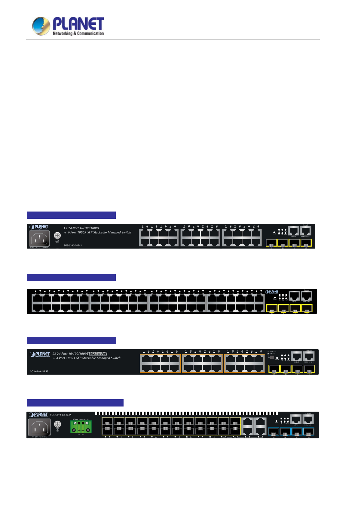
User’s Manual of SGS-6340 seriesT
Chapter 2 INSTALLATION
This section describes how to install your Managed Switch and make connections to the Managed Switch.
Please read the following topics and perform the procedures in the order being presented. To install your Managed
Switch on a desktop or shelf, simply complete the following steps.
In this paragraph, we will describe how to install the Managed Switch and the installation points attended to it.
2.1 Hardware Description
2.1.1 Switch Front Panel
The unit front panel provides a simple interface monitoring the switch. Figure 2-1~ Figure 2-4 shows the front panel
of the Managed Switch.
SGS-6340-24T4S Front Panel
Figure 2-1 SGS-6340-24T4S front panel
SGS-6340-48T4S Front Panel
Figure 2-2 SGS-6340-48T4S front panel
SGS-6340-24P4S Front Panel
SGS-6340-20S4C4X Front Panel
Figure 2-4 SGS-6340-20S4C4X Front Panel
Figure 2-3 SGS-6340-24P4S front panel
17
Page 35

User’s Manual of SGS-6340 seriesT
SGS-6340-16XR Front Panel
Figure 2-4 SGS-6340-16XR Front Panel
■ Gigabit TP interface
10/100/1000BASE-T Copper, RJ45 Twisted-pair: Up to 100 meters.
■ Gigabit SFP slots
100/1000BASE-X mini-GBIC slot, SFP (Small Factor Pluggable) transceiver module: From 550 meters to 2km
(multi-mode fiber), up to above 10/20/30/40/50/70/120 kilometers (single-mode fiber). Only
SGS-6340-20S4C4X supports 100BASE-FX.
■ 10 Gigabit SFP slot
10GBASE-SR/LR mini-GBIC slot, SFP (Small Factor Pluggable) Transceiver Module supports from 300
meters (Multi-mode Fiber), up to 10 kilometers (Single Mode Fiber)
■ Console Port
The console port is a RJ45 port connector. It is an interface for connecting a terminal directly. Through the
console port, it provides rich diagnostic information including IP Address setting, factory reset, port
management, link status and system setting. Users can use the attached DB9 to RJ45 console cable in the
package and connect to the console port on the device. After the connection, users can run any terminal
emulation program (Hyper Terminal, ProComm Plus, Telix, Winterm and so on) to enter the startup screen of
the device.
■ Reset button
On the front panel, the reset button is designed for rebooting the Managed Switch without turning off and on
the power.
■ DC Power Connector (SGS-6340-20S4C4X only)
The front panel of the Managed Switch contains a power switch and a DC power connector, which accepts DC
power input voltage from -48V to -60V DC. Connect the power cable to the Managed Switch at the input
terminal block.
The wire gauge for the terminal block should be in the range of 12 ~ 24 AWG.
18
Page 36

User’s Manual of SGS-6340 seriesT
2.1.2 LED Indications
The front panel LEDs indicate instant status of port links, data activity, system operation, stack status and system
power.
SGS-6340-24T4S LED Indication
stem
■ Sy
LED Color Function
PWR
SYS Green
■ 10/100/1000BASE-T Interfaces
LED Color Function
LNK/ACT
Green Lights to indicate that the Switch has power.
Off Power is off.
Lights to indicate the system diagnosis is completed.
Blinks to indicate boot is enable.
Lights to indicate the link through that port is successfully established
Green
Blinks to indicate that the switch is actively sending or receiving data over that
port.
Figure 2-5 SGS-6340-24T4S LED Panel
■ SFP Interfaces
LED Color Function
LNK/ACT
Off
Green
Off
No flow goes through the port.
Lights to indicate the link through that port is successfully established
No flow goes through the port.
19
Page 37

SGS-6340-48T4S LED Indication
stem
■ Sy
User’s Manual of SGS-6340 seriesT
Figure 2-6 SGS-6340-48P4S LED Panel
LED Color Function
Green Lights to indicate that the Switch has power.
PWR
Off Power is off.
Lights to indicate the system diagnosis is completed.
SYS Green
Blinks to indicate boot is enable.
■ 10/100/1000BASE-T Interfaces
LED Color Function
Lights to indicate the link through that port is successfully established
LNK/ACT
Green
Blinks to indicate that the switch is actively sending or receiving data over that
port.
Off
No flow goes through the port.
■ SFP Interfaces
LED Color Function
Green
Lights to indicate the link through that port is successfully established
LNK/ACT
Off
No flow goes through the port.
20
Page 38

SGS-6340-24P4S LED Indication
User’s Manual of SGS-6340 seriesT
■
stem
Sy
LED Color Function
Green Lights to indicate that the Switch has power.
PWR
Off Power is off.
Lights to indicate the system diagnosis is completed.
SYS Green
Blinks to indicate boot is enable.
■ 10/100/1000BASE-T Interfaces
LED Color Function
Lights to indicate the link through that port is successfully established
Green
Blinks to indicate that the switch is actively sending or receiving data over that
LNK/ACT
port.
Figure 2-7 SGS-63
40-24P
4S LED Pane
l
PoE In-Use Green
■ SFP Interfaces
LED Color Function
LNK/ACT
Off
Green
Off
No flow goes through the port.
Lights to indicate the port is providing 54V DC in-line power.
Lights to indicate the link through that port is successfully established
No flow goes through the port.
21
Page 39

SGS-6340-20S4C4X LED Indication
Figure 2-8 SGS-6340-20S4C4X LED Panel
stem
■ Sy
LED Color Function
User’s Manual of SGS-6340 seriesT
PWR
Green Lights to indicate that the Switch has power.
Off Power is off.
Lights to indicate the system diagnosis is completed.
SYS Green
Blinks to indicate boot is enable.
■ 10/100/1000BASE-T Interfaces
LED Color Function
Lights to indicate the link through that port is successfully established
LNK/ACT
Green
Blinks to indicate that the switch is actively sending or receiving data over that
port.
Off
No flow goes through the port.
■ 100/1000X SFP Interfaces
LED Color Function
LNK/ACT
Green
Off
■ 1/10G SFP+ Interfaces
LED Color Function
Green
LNK/ACT
Off
Lights to indicate the link through that port is successfully established
No flow goes through the port.
Lights to indicate the link through that port is successfully established
No flow goes through the port.
22
Page 40

SGS-6340-16XR LED Indication
User’s Manual of SGS-6340 seriesT
Figure 2-8 SGS-6340-16XR LED Panel
■ Sy
stem/Alarm
LED Color Function
Green Lights to indicate that the Switch has power.
PWR
Off Power is off.
Green Blinks to indicate the system diagnosis is completed.
SYS
Off System is booting.
FAN Red Lights to indicate that the Switch has fan fault.
23
Page 41

User’s Manual of SGS-6340 seriesT
2.1.3 Switch Rear Panel
The rear panel of the Managed Switch indicates an AC inlet power socket, which accepts input power from 100 to
240V AC, 50-60Hz. Figure 2-9 ~ Figure 2-12 shows the rear panel of this Managed Switch.
SGS-6340-24T4S Rear Panel
Figure 2-9 Rear Panel of SGS-6340-24T4S
SGS-6340-48T4S Rear Panel
SGS-6340-24P4S Rear Panel
SGS-6340-20S4C4X Rear Panel
Figure 2-12 Rear Panel of SGS-6340-20S4C4X
SGS-6340-16XR Rear Panel
Figure 2-10 Rear Panel of SGS-6340-48T4S
Figure 2-11 Rear Panel of SGS-6340-24P4S
Figure 2-12 Rear Panel of SGS-6340-16XR
24
Page 42

User’s Manual of SGS-6340 seriesT
■ AC Power Receptacle
For compatibility with electric service in most areas of the world, the Managed Switch’s power supply
automatically adjusts to line power in the range of 100-240VAC and 50/60 Hz.
Plug the female end of the power cord firmly into the receptacle on the rear panel of the Managed Switch. Plug
the other end of the power cord into an electric service outlet then the power will be ready.
■ DC Power Connector (SGS-6340-16XR only)
The front panel of the Managed Switch contains a power switch and a DC power connector, which accepts DC
power input voltage from -48V to -60V DC. Connect the power cable to the Managed Switch at the input
terminal block.
The device is a power-required device, meaning it will not work till it is powered. If your
networks should be active all the time, please consider using UPS (Uninterruptible Power
Supply) for your device. It will prevent you from network data loss or network downtime.
Power Notice:
In some areas, installing a surge suppression device may also help to protect your
Managed Switch from being damaged by unregulated surge or current to the Switch or the
power adapter.
25
Page 43

User’s Manual of SGS-6340 seriesT
2.2 Installing the Managed Switch
This section describes how to install your Managed Switch and make connections to the Managed Switch.
Please read the following topics and perform the procedures in the order being presented. To install your Managed
Switch on a desktop or shelf, simply complete the following steps.
In this paragraph, we will describe how to install the Managed Switch and the installation points attended to it.
2.2.1 Desktop Installation
To install the Managed Switch on desktop or shelf, please follows these steps:
Step 1: Attach the rubber feet to the recessed areas on the bottom of the Managed Switch.
Step 2: Place the Managed Switch on the desktop or the shelf near an AC power source, as shown in Figure 2-13.
Figure 2-13 Place the Managed Switch on the desk
Step 3: Keep enough ventilation space between the Managed Switch and the surrounding objects.
Step 4: Connect the Managed Switch to network devices.
Connect one end of a standard network cable to the 10/100/1000 RJ45 ports on the front of the Managed
Switch. Connect the other end of the cable to the network devices such as printer servers, workstations,
routers or others.
Connection to the Managed Switch requires UTP Category 5 network cabling with RJ45
tips. For more information, please see the Cabling Specification in Appendix A.
26
Page 44

User’s Manual of SGS-6340 seriesT
Step 5: Supply power to th
Connect one end of the power cable to the Managed Switch. Connect the power plug of the power
cable into a standard wall outlet. When the Managed Switch receives power, the Power LED should
remain solid Green.
e Managed Switch.
2.2.2 Rack Mounting
To install the Managed Switch in a 19-inch standard rack, please follow the instructions described below.
Step 1: Place the Managed Switch on a hard flat surface, with the front panel positioned towards the front side.
Step 2: Attach the rack-mount bracket to each side of the Managed Switch with supplied screws attached to the
package. Figure 2-14 shows how to attach brackets to one side of the Managed Switch.
Figure 2-14 Attach brackets to the Managed Switch.
You must use the screws supplied with the mounting brackets. Damage caused to the
parts by using incorrect screws would invalidate the warranty.
Step 3: Secure the brackets tightly.
Step 4: Follow the same steps to attach the second bracket to the opposite side.
Step 5: After the brackets are attached to the Managed Switch, use suitable screws to securely attach the brackets
to the rack, as shown in Figure 2-15.
27
Page 45

User’s Manual of SGS-6340 seriesT
in a Rack
Step 6:
Figure 2-15 Mounting SGS-6340 Series
Proceeds with steps 4 and 5 of session 2.2.1 Desktop Installation to connect the network cabling and
supply power to the Managed Switch.
2.2.3 Installing the SFP/SFP+ Transceiver
The sections describe how to insert an SFP/SFP+ transceiver into an SFP/SFP+ slot. The SFP/SFP+ transceivers
are hot-pluggable and hot-swappable. You can plug in and out the transceiver to/from any SFP/SFP+ port without
having to power down the Managed Switch, as the Figure 2-16 shows.
Figure 2-16 Plug in the SFP transceiver
28
Page 46

User’s Manual of SGS-6340 seriesT
Approved PLANET SFP/SFP+ Transceivers
PLANET Managed Switch supports both single mode and multi-mode SFP/SFP+ transceivers. The following list of
approved PLANET SFP/SFP+ transceivers is correct at the time of publication:
Fast Ethernet Transceiver (100BASE-X SFP)
Model Speed (Mbps)
MFB-FX 100 LC Multi Mode 2km 1310nm 0 ~ 60 degrees C
MFB-F20 100 LC Single Mode
MFB-F40 100 LC Single Mode
MFB-F60 100 LC Single Mode
MFB-F120 100 LC Single Mode 120km 1550nm 0 ~ 60 degrees C
MFB-TFX 100 LC Multi Mode 2km 1310nm -40 ~ 75 degrees C
MFB-TF20 100 LC Single Mode
Connector Interface
Fiber Mode Distance Wavelength (nm) Operating Temp.
20km 1310nm 0 ~ 60 degrees C
40km 1310nm 0 ~ 60 degrees C
60km 1310nm 0 ~ 60 degrees C
20km 1550nm -40 ~ 75 degrees C
Fast Ethernet Transceiver (100BASE-BX, Single Fiber Bi-directional SFP)
Model Speed (Mbps)
MFB-FA20 100 WDM(LC) Single Mode 20km 1310nm/1550nm 0 ~ 60 degrees C
MFB-FB20 100 WDM(LC) Single Mode 20km 1550nm/1310nm 0 ~ 60 degrees C
MFB-TFA20 100 WDM(LC) Single Mode 20km 1310nm/1550nm -40 ~ 75 degrees C
MFB-TFB20 100 WDM(LC) Single Mode 20km 1550nm/1310nm -40 ~ 75 degrees C
MFB-TFA40 100 WDM(LC) Single Mode 40km 1310nm/1550nm -40 ~ 75 degrees C
MFB-TFB40 100 WDM(LC) Single Mode 40km 1550nm/1310nm -40 ~ 75 degrees C
Connector Interface
Fiber Mode Distance Wavelength (TX/RX) Operating Temp.
Gigabit Ethernet Transceiver (1000BASE-X SFP)
Model Speed (Mbps)
MGB-GT 1000 Copper -- 100m -- 0 ~ 60 degrees C
MGB-SX 1000 LC Multi Mode 550m 850nm 0 ~ 60 degrees C
MGB-SX2 1000 LC Multi Mode 2km 1310nm 0 ~ 60 degrees C
MGB-LX 1000 LC Single Mode 10km 1310nm 0 ~ 60 degrees C
MGB-L30 1000 LC Single Mode 30km 1310nm 0 ~ 60 degrees C
MGB-L50 1000 LC Single Mode 50km 1550nm 0 ~ 60 degrees C
MGB-L70 1000 LC Single Mode 70km 1550nm 0 ~ 60 degrees C
MGB-L120 1000 LC Single Mode 120km
MGB-TSX 1000 LC Multi Mode 550m 850nm -40 ~ 75 degrees C
MGB-TLX 1000 LC Single Mode 10km 1310nm -40 ~ 75 degrees C
MGB-TL30 1000 LC Single Mode 30km 1310nm -40 ~ 75 degrees C
MGB-TL70 1000 LC Single Mode 70km 1550nm -40 ~ 75 degrees C
Connector Interface
Fiber Mode Distance Wavelength (nm) Operating Temp.
1550nm 0 ~ 60 degrees C
29
Page 47

User’s Manual of SGS-6340 seriesT
Gigabit Ethernet Transceiver (1000BASE-BX, Single Fiber Bi-directional SFP)
Model Speed (Mbp s)
MGB-LA10 1000 WDM(LC) Single Mode 10km 1310nm/1550nm 0 ~ 60 degrees C
MGB-LB10 1000 WDM(LC) Single Mode 10km 1550nm/1310nm 0 ~ 60 degrees C
MGB-LA20 1000 WDM(LC) Single Mode 20km 1310nm/1550nm 0 ~ 60 degrees C
MGB-LB20 1000 WDM(LC) Single Mode 20km 1550nm/1310nm 0 ~ 60 degrees C
MGB-LA40 1000 WDM(LC) Single Mode 40km 1310nm/1550nm 0 ~ 60 degrees C
MGB-LB40 1000 WDM(LC) Single Mode 40km 1550nm/1310nm 0 ~ 60 degrees C
MGB-LA60 1000 WDM(LC) Single Mode 60km 1310nm/1550nm 0 ~ 60 degrees C
MGB-LB60 1000 WDM(LC) Single Mode 60km 1550nm/1310nm 0 ~ 60 degrees C
MGB-TLA10 1000 WDM(LC) Single Mode 10km 1310nm/1550nm -40 ~ 75 degrees C
MGB-TLB10 1000 WDM(LC) Single Mode 10km 1550nm/1310nm -40 ~ 75 degrees C
MGB-TLA20 1000 WDM(LC) Single Mode 20km 1310nm/1550nm -40 ~ 75 degrees C
MGB-TLB20 1000 WDM(LC) Single Mode 20km 1550nm/1310nm -40 ~ 75 degrees C
MGB-TLA40 1000 WDM(LC) Single Mode 40km 1310nm/1550nm -40 ~ 75 degrees C
MGB-TLB40 1000 WDM(LC) Single Mode 40km 1550nm/1310nm -40 ~ 75 degrees C
MGB-TLA60 1000 WDM(LC) Single Mode 60km 1310nm/1550nm -40 ~ 75 degrees C
MGB-TLB60 1000 WDM(LC) Single Mode 60km 1550nm/1310nm -40 ~ 75 degrees C
Connector Interface
Fiber Mode Distance Wavelength (TX/RX) Operating Temp.
10Gbps SFP+ (10G Ethernet/10GBASE)
Model Speed (Mbps)
MTB-SR 10G LC Multi Mode Up to 300m
MTB-LR 10G LC Single Mode 10km 1310nm 0 ~ 60 degrees C
Connector
Interface
Fiber Mode
10Gbps SFP+ (10GBASE-BX, Single Fiber Bi-directional SFP)
Model Speed (Mbps)
MTB-LA20
MTB-LB20
MTB-LA40
MTB-LB40
MTB-LA60
MTB-LB60
10G WDM(LC) Single Mode 20km 1270nm 1330nm 0 ~ 60 degrees C
10G WDM(LC) Single Mode 20km 1330nm 1270nm 0 ~ 60 degrees C
10G WDM(LC) Single Mode 40km 1270nm 1330nm 0 ~ 60 degrees C
10G WDM(LC) Single Mode 40km 1330nm 1270nm 0 ~ 60 degrees C
10G WDM(LC) Single Mode 60km 1270nm 1330nm 0 ~ 60 degrees C
10G WDM(LC) Single Mode 60km 1330nm 1270nm 0 ~ 60 degrees C
Connector
Interface
Fiber Mode Distance
Wavelength
Distance Wavelength (nm) Operating Temp.
850nm 0 ~ 60 degrees C
Wavelength (RX) Operating Temp.
(TX)
It is recommended to use PLANET SFP/SFP+ on the Managed Switch. If you insert an
SFP/SFP+ transceiver that is not supported, the Managed Switch will not recognize it.
30
Page 48

User’s Manual of SGS-6340 seriesT
1. Before we conne
ct the SGS-6340 Series to the other network device, we have to make sure both sides of the
SFP transceivers are with the same media type, for example: 1000BASE-SX to 1000BASE-SX, 1000Bas-LX
to 1000BASE-LX.
2. Check whether the fiber-optic cable type matches with the SFP transceiver requirement.
To connect to 1000BASE-SX SFP transceiver, please use the multi-mode fiber cable with one side being
the male duplex LC connector type.
To connect to 1000BASE-LX SFP transceiver, please use the single-mode fiber cable with one side being
the male duplex LC connector type.
Connect the Fiber Cable
1. Insert the duplex LC connector into the SFP/SFP+ transceiver.
2. Connect the other end of the cable to a device with SFP/SFP+ transceiver installed.
3. Check the LNK/ACT LED of the SFP/SFP+ slot on the front of the Managed Switch. Ensure that the
SFP/SFP+ transceiver is operating correctly.
4. Check the Link mode of the SFP/SFP+ port if the link fails. To function with some fiber-NICs or Media
Converters, user has to set the port Link mode to “10G Force”, “1000M Force” or “100M Force”.
Remove the Transceiver Module
1. Make sure there is no network activity anymore.
2. Remove the Fiber-Optic Cable gently.
3. Lift up the lever of the MGB module and turn it to a horizontal position.
4. Pull out the module gently through the lever.
Figure 2-17: How to Pull Out the SFP/SFP+ Transceiver
Never pull out the module without lifting up the lever of the module and turning it to a
horizontal position. Directly pulling out the module could damage the module and the
SFP/SFP+ module slot of the Managed Switch.
31
Page 49

Chapter 3 Switch Management
3.1 Management Options
After purchasing the switch, the user needs to configure the switch for network management. Switch provides
two management options: in-band management and out-of-band management.
3.1.1 Out-Of-Band Management
Out-of-band management is the management through Console interface. Generally, the user will use
out-of-band management for the initial switch configuration, or when in-band management is not available.
For instance, the SGS-6340 Series default IP address is 192.168.0.254 or the user can try to assign a new IP
address to the switch via the Console interface to be able to access the switch through Telnet.
The procedures for managing the switch via Console interface are listed below:
Step 1: Setting up the environment:
Figure 3-1 Out-of-band Management Configuration Environment
As shown in the above, the serial port (RS232) is connected to the switch with the serial cable provided. The
table below lists all the devices used in the connection.
Device Name Description
PC machine Has functional keyboard and RS232, with terminal emulator
installed, such as Tera Term and hyper terminal.
Serial port cable One end is connected to the RS232 serial port; the other end to
the console port.
Switch Functional console port required.
3-1
Page 50

2: Entering the HyperTerminal
Step
Open the HyperTerminal included in Windows after the connection established. The example below is based
on the HyperTerminal included in Windows XP.
1) Click Start menu - All Programs -Accessories -Communication - HyperTerminal.
Figure 3-2 Opening Hyper Terminal
2) Type a name for opening HyperTerminal, such as “Switch”.
Figure 3-3 Opening HyperTerminal
3-2
Page 51
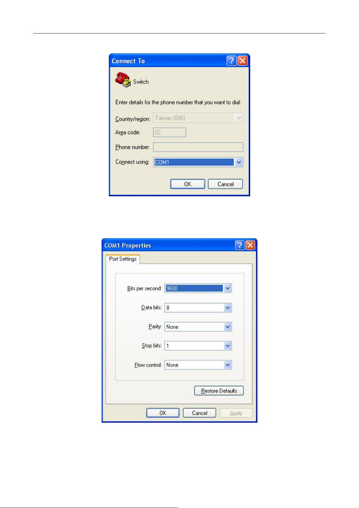
3) In the “Connect us
4) COM1 property appears and select “9600” for “Baud rate”, “8” for “Data bits”, “none” for “Parity checksum”,
“1” for stop bit and “none” for traffic control; or you can also click “Restore default” and click “OK”.
ing” drop-list, select the RS-232 serial port used by the PC, e.g., COM1, and click “OK”.
Figure 3-4 Opening HyperTerminal
Figure 3-5 Opening HyperTerminal
Step 3: Entering switch CLI interface
Power on the switch and the following appears in the HyperTerminal windows, that is the CLI configuration
mode for Switch.
3-3
Page 52

System is booting, please wait...
Bootrom version: 7.1.37
Creation date: Aug 15 2014 - 16:59:42
Testing RAM...
0x10000000 RAM OK.
Loading flash:/nos.img ...
## Booting kernel from Legacy Image at 62000100 ...
Image Name: Linux-3.6.5+
Image Type: ARM Linux Kernel Image (gzip compressed)
Data Size: 11772899 Bytes = 11.2 MiB
Load Address: 60008000
Entry Point: 60008000
Verifying Checksum ... OK
Uncompressing Kernel Image ... OK
Starting kernel ...
Current time is Sun Jan 01 00:00:00 2006
SGS-6340 Series Switch Operating System
Software Version 7.0.3.5(R0102.0087)
Compiled Aug 22 12:20:28 2014
52 Ethernet/IEEE 802.3 interface(s)
Mac Addr 00-30-4f-23-45-67
Recover config from file flash:/startup.cfg
Loading startup-config ...
……
Switch>
The user can now enter commands to manage the switch. For a detailed description of the commands, please
refer to the following chapters.
3-4
Page 53

3.1.2 In-band Management
In-band management refers to the management by login to the switch using Telnet, or using HTTP, or using
SNMP management software to configure the switch. In-band management enables management of the
switch for some devices attached to the switch. In the case when in-band management fails due to switch
configuration changes, out-of-band management can be used for configuring and managing the switch.
3.1.2.1 Management via Telnet
To manage the switch with Telnet, the following conditions should be met:
1) Switch has an IPv4/IPv6 address configured;
2) The host IP address (Telnet client) and the switch’s VLAN interface IPv4/IPv6 address is in the same
network segment;
3) If 2) is not met, Telnet client can connect to an IPv4/IPv6 address of the switch via other devices,
such as a router.
The switch is Layer 3 switch that can be configured with several IPv4/IPv6 addresses. The following example
assumes the shipment status of the switch where only VLAN1 exists in the system. The following describes
the steps for a Telnet client to connect to the switch’s VLAN1 interface by Telnet (with IPv4 address as an
example):
Figure 3-6 Manage the Switch by Telnet
Step 1: Configure the IP addresses for the switch and start the Telnet Server function on the switch. First is
the configuration of host IP address. This should be within the same network segment as the switch VLAN1
interface IP address. Suppose the switch VLAN1 interface IP address is 10.1.128.251/24. Then, a possible
host IP address is 10.1.128.252/24. Run “ping 10.1.128.251” from the host and verify the result. Check for
reasons if ping fails.
The IP address configuration commands for VLAN1 interface are listed below. Before in-band management is
used, the switch must be configured with an IP address by out-of-band management (i.e. Console mode). The
configuration commands are as follows (All switch configuration prompts are assumed to be “Switch”
hereafter if not otherwise specified.):
Switch#
Switch#config
Switch (config)#interface vlan 1
Switch (Config-if-Vlan1)#ip address 10.1.128.251 255.255.255.0
Switch (Config-if-Vlan1)#no shutdown
3-5
Page 54

Step 2: Run
Telnet Client program.
Run Telnet client program included in Windows with the specified Telnet target.
Figure 3-7 Run telnet client program included in Windows
Step 3: Login to the switch.
Login to the Telnet configuration interface. Valid login name and password are required, otherwise, the switch
will reject Telnet access. This is the method to protect the switch from unauthorized access. As a result, when
Telnet is enabled for configuring and managing the switch, username and password for authorized Telnet
users must be configured with the following command:
username <username> privilege <privilege> [password (0|7) <password>]
To open the local authentication style with the following command: authentication line vty login local. Privilege
option must exist and just is 15. Assume an authorized user in the switch has a username of “test”, and
password of “test”, the configuration procedure should like the following:
Switch#
Switch#config
Switch (config)#username test privilege 15 password 0 test
Switch (config)#authentication line vty login local
Enter valid login name and password in the Telnet configuration interface, Telnet user will be able to enter the
switch’s CLI configuration interface. The commands used in the Telnet CLI interface after login is the same as
that in the Console interface.
Figure 3-8 Telnet Configuration Interface
3-6
Page 55

3.1.2.2 Management via HTTP
To manage the switch via HTTP, the following conditions should be met:
1) Switch has an IPv4/IPv6 address configured;
2) The host IPv4/IPv6 address (HTTP client) and the switch’s VLAN interface IPv4/IPv6 address are in
the same network segment;
3) If 2) is not met, HTTP client should connect to an IPv4/IPv6 address of the switch via other devices,
such as a router.
Similar to management the switch via Telnet, as soon as the host succeeds to ping/ping6 an IPv4/IPv6
address of the switch and to type the right login password, it can access the switch via HTTP. The
configuration list is shown below:
Step 1: Configure the IP addresses for the switch and start the HTTP server function on the switch.
For configuring the IP address on the switch through out-of-band management, see the Telnet management
chapter.
To enable the Web configuration, users should type the CLI command IP http server in the global mode as
shown below:
Switch#
Switch#config
Switch (config)#ip http server
Step 2: Run HTTP protocol on the host.
Open the Web browser on the host and type the IP address of the switch, or run directly the HTTP protocol on
the Windows. For example, the IP address of the switch is “10.1.128.251”;
Figure 3-9 Run HTTP Protocol
When accessing a switch with IPv6 address, it is recommended to use the Firefox browser with 1.5 or later
version. For example, if the IPv6 address of the switch is 3ffe:506:1:2::3, the IPv6 address of the switch
should be http://[3ffe:506:1:2::3]. Please note the address should be in the square brackets.
3-7
Page 56

Step 3:
Login to the switch.
Login to the Web configuration interface. Valid login name and password are required, otherwise, the switch
will reject HTTP access. This is the method to protect the switch from unauthorized access. As a result, when
Telnet is enabled for configuring and managing the switch, username and password for authorized Telnet
users must be configured with the following command:
username <username> privilege <privilege> [password (0|7) <password>]
To open the local authentication style with the following command: authentication line web login local.
Privilege option must exist and is just 15. Assume an authorized user in the switch has a username “admin”,
and password “admin”, the configuration procedure should be as follows:
Switch#
Switch#config
Switch (config)#username admin privilege 15 password 0 admin
Switch (config)#authentication line web login local
The Web login interface of SGS-6340 Series is shown below:
Figure 3-10 Web Login Interface
3-8
Page 57

Input the right username an
d password and then the main Web configuration interface is shown below.
Figure 3-11 Main Web Configuration Interface
When configuring the switch, the name of the switch is composed of English letters.
3.1.2.3 Manage the Switch via SNMP Network Management Software
The followings are required by SNMP network management software to manage switches:
1) IP addresses are configured on the switch;
2) The IP address of the client host and that of the VLAN interface on the switch it subordinates to
should be in the same segment;
3) If 2) is not met, the client should be able to reach an IP address of the switch through devices like
routers;
4) SNMP should be enabled.
The host with SNMP network management software should be able to ping the IP address of the switch, so
that when running, SNMP network management software will be able to find it and implement read/write
operation on it. Details about how to manage switches via SNMP network management software will not be
covered in this manual; please refer to “Simple Network Management software user manual”.
3.2 CLI Interface
The switch provides three management interfaces for users: CLI (Command Line Interface) interface, Web
interface and Simple Network Management software. We will introduce the CLI interface and Web
configuration interface in details. Web interface is familiar with CLI interface function and will not be covered.
Please refer to “Simple Network Management software user manual”.
3-9
Page 58

CLI interface
performed through CLI interface to manage the switch.
CLI Interface is supported by Shell program, which consists of a set of configuration commands. Those
commands are categorized according to their functions in switch configuration and management. Each
category represents a different configuration mode. The Shell for the switch is described below:
Configuration Modes
Configuration Syntax
Shortcut keys
Help function
Input verification
Fuzzy match support
is familiar to most users. As aforementioned, out-of-band management and Telnet login are all
3-10
Page 59

3.2.1 Configuration Modes
Figure 3-12 Shell Configuration Modes
3.2.1.1 User Mode
On entering the CLI interface, entering user entry system first. If as common user, it is defaulted to User Mode.
The prompt shown is “Switch>“, the symbol “>“ is the prompt for User Mode. When exit command is run
under Admin Mode, it will also return to the User Mode.
Under User Mode, no configuration to the switch is allowed; only clock time and version information of the
switch can be queried.
3.2.1.2 Admin Mode
Admin Mode sees the following: In user entry system, if as Admin user, it is defaulted to Admin Mode. Admin
Mode prompt “Switch#” can be entered under the User Mode by running the enable command and entering
corresponding access levels admin user password, if a password has been set. Or, when exit command is run
under Global Mode, it will also return to the Admin Mode. Switch also provides a shortcut key sequence
"Ctrl+z”, this allows an easy way to exit to Admin Mode from any configuration mode (except User Mode).
Under Admin Mode, the user can query the switch configuration information, connection status and traffic
statistics of all ports; the user can further enter the Global Mode from Admin Mode to modify all configurations
of the switch. For this reason, a password must be set for entering Admin mode to prevent unauthorized
access and malicious modification to the switch.
3-11
Page 60

3.2.1.3 Global Mode
Type the config command under Admin Mode to enter the Global Mode prompt “Switch(config)#”. Use the
exit command under other configuration modes such as Port Mode, VLAN mode to return to Global Mode.
The user can perform global configuration settings under Global Mode, such as MAC Table, Port Mirroring,
VLAN creation, IGMP Snooping start and STP, etc. And the user can go further to Port Mode for configuration
of all the interfaces.
Interface Mode
Use the interface command under Global Mode to enter the interface mode specified. Switch provides three
interface types: 1. VLAN interface; 2. Ethernet port; 3. port-channel, according to the three interface
configuration modes.
Interface Type Entry Operates Exit
VLAN Interface
Ethernet Port
port-channel
Type interface vlan <Vlan-id>
command under Global Mode.
Type interface Ethernet
<interface-list> command
under Global Mode.
Type interface port-channel
<port-channel-number>
command under Global Mode.
VLAN Mode
Using the vlan <vlan-id> command under Global Mode to enter the corresponding VLAN Mode. Under
VLAN Mode the user can configure all member ports of the corresponding VLAN. Run the exit command
to exit the VLAN Mode to Global Mode.
DHCP Address Pool Mode
Type the ip dhcp pool <name> command under Global Mode to enter the DHCP Address Pool Mode
prompt “Switch(Config-<name>-dhcp)#”. DHCP address pool properties can be configured under DHCP
Address Pool Mode. Run the exit command to exit the DHCP Address Pool Mode to Global Mode.
ACL Mode
ACL type Entry Operates Exit
Standard IP ACL
Mode
Extended IP ACL
Mode
Type ip access-list
standard command under
Global Mode.
Type ip access-list
extended command under
Global Mode.
Configure switch IPs, etc Use the exit command
to return to Global
Mode.
Configure supported
duplex mode, speed, etc.
of Ethernet Port.
Configure port-channel
related settings such as
duplex mode, speed, etc.
Configure parameters
for Standard IP ACL
Mode.
Configure parameters
for Extended IP ACL
Mode.
Use the exit command
to return to Global
Mode.
Use the exit command
to return to Global
Mode.
Use the exit
command to return
to Global Mode.
Use the exit
command to return
to Global Mode.
3-12
Page 61

3.2.2 Configuration Syntax
Switch provides various configuration commands. Although all the commands are different, they all abide by
the syntax for Switch configuration commands. The general commands format of Switch is shown below:
cmdtxt <variable> {enum1 | … | enumN } [option1 | … | optionN]
Conventions: cmdtxt in bold font indicates a command keyword; <variable> indicates a variable parameter;
{enum1 | … | enumN } indicates a mandatory parameter that should be selected from the parameter set
enum1~enumN; and the square bracket ([ ]) in [option1 | … | optionN] indicate an optional parameter. There
may be combinations of “< >“, “{ }” and “[ ]” in the command line, such as [<variable>], {enum1 <variable>|
enum2}, [option1 [option2]], etc.
Here are examples for some actual configuration commands:
show version, no parameters required. This is a command with only a keyword and no parameter, just
type in the command to run.
vlan <vlan-id>, parameter values are required after the keyword.
firewall {enable | disable}, user can enter firewall enable or firewall disable for this command.
snmp-server community {ro | rw} <string>, the followings are possible:
snmp-server community ro <string>
snmp-server community rw <string>
3-13
Page 62

3.2.3 Shortcut Key Support
Switch provides several shortcut keys to facilitate user configuration, such as up, down, left, right and blank
space. If the terminal does not recognize Up and Down keys, ctrl +p and ctrl +n can be used instead.
Key(s)
Back Space
Up “↑”
Down “↓”
Left “←”
Right “→”
Ctrl +p
Ctrl +n
Ctrl +b
Ctrl +f
Ctrl +z
Ctrl +c
Tab
Function
Delete a character before the cursor, and the cursor moves back.
Show previous command entered. Up to ten recently entered
commands can be shown.
Show next command entered. When use the Up key to get previously
entered commands, you can use the Down key to return to the next
command
The cursor moves one character to
the left.
The cursor moves one character to
the right.
The same as Up key “↑”.
The same as Down key “↓”.
The same as Left key “←”.
The same as Right key “→”.
Return to the Admin Mode directly from the other configuration modes
(except User Mode).
Break the ongoing command process, such as ping or other command
execution.
When a string for a command or keyword is entered, the Tab can be
used to complete the command or keyword if there is no conflict.
You can use the Left and
Right key to modify an
entered command.
3.2.4 Help Function
There are two ways in Switch for the user to access help information: the “help” command and the “?”.
Access to Help
Help
“?”
Usage and function
Under any command line prompt, type in “help” and press Enter will get a
brief description of the associated help system.
1. Under any command line prompt, enter “?” to get a command list of
the current mode and related brief description.
2. Enter a “?” after the command keyword with an embedded space. If
the position should be a parameter, a description of that parameter
type, scope, etc, will be returned; if the position should be a keyword,
then a set of keywords with brief description will be returned; if the
output is “<cr>“, then the command is complete, press Enter to run the
command.
3. A “?” immediately following a string. This will display all the commands
that begin with that string.
3-14
Page 63

3.2.5 Input Verification
3.2.5.1 Returned Information: Successful
All commands entered through keyboards undergo syntax check by the Shell. Nothing will be returned if the
user enters a correct command under corresponding modes and the execution is successful.
Returned Information: error
Output error message Explanation
Unrecognized command or illegal
parameter!
Ambiguous command
Invalid command or parameter
This command does not exist in
current mode
Please configure precursor
command "*" first!
syntax error : missing '"' before the
end of command line!
The entered command does not exist, or there is
error in parameter scope, type or format.
At least two interpretations are possible based on
the current input.
The command is recognized, but no valid
parameter record is found.
The command is recognized, but this command
cannot be used under current mode.
The command is recognized, but the prerequisite
command has not been configured.
Quotation marks are not used in pairs.
3.2.6 Fuzzy Match Support
Switch shell supports fuzzy match in searching command and keyword. Shell will recognize commands or
keywords correctly if the entered string causes no conflict.
For example:
1) For command “show interfaces status ethernet1/1”, typing “sh in status ethernet1/1” will work.
2) However, for command “show running-config”, the system will report a “> Ambiguous command!”
error if only “show r” is entered, as Shell is unable to tell whether it is “show run” or “show
running-config”. Therefore, Shell will only recognize the command if “sh ru” is entered.
3-15
Page 64

Chapter 4 Basic Switch Configuration
4.1 Basic Configuration
Basic switch configuration includes commands for entering and exiting the admin mode, for
entering and exiting interface mode, for configuring and displaying the switch clock, for
displaying the version information of the switch system, etc.
Command Explanation
Normal User Mode/ Admin Mode
The User uses enable command to step into
enable [<1-15>]
disable
Admin Mode
config [terminal]
Various Modes
exit
show privilege
Except User Mode/ Admin Mode
end
Admin Mode
clock set <HH:MM:SS>
[YYYY.MM.DD]
admin mode from normal user mode or modify
the privilege level of the users. The disable
command is for exiting admin mode.
Enter global mode from admin mode.
Exit current mode and enter previous mode,
such as using this command in global mode to
go back to admin mode, and back to normal
user mode from admin mode.
Show privilege of the current users.
Quit current mode and return to Admin mode
when not in User Mode/ Admin Mode.
Set system date and time.
show version
set default
write
reload
show cpu usage
show cpu utilization
show memory usage
Global Mode
Display version information of the switch.
Restore to the factory default.
Save current configuration parameters to Flash
Memory.
Reset the switch.
Show CPU usage rate.
Show current CPU utilization rate.
Show memory usage rate.
4-1
Page 65

banner motd <LINE>
no banner motd
Configure the information displayed when the
login authentication of a Telnet or console user is
successful.
4.2 Telnet Management
4.2.1 Telnet
4.2.1.1 Introduction to Telnet
Telnet is a simple remote terminal protocol for remote login. Using Telnet, the user can login to
a remote host with its IP address of hostname from his own workstation. Telnet can send the
user’s keystrokes to the remote host and send the remote host output to the user’s screen
through TCP connection. This is a transparent service, as to the user, the keyboard and
monitor seems to be connected to the remote host directly.
Telnet employs the Client-Server mode; the local system is the Telnet client and the remote
host is the Telnet server. Switch can be either the Telnet Server or the Telnet client. When
switch is used as the Telnet server, the user can use the Telnet client program included in
Windows or other operating systems to login to switch, as described earlier in the In-band
Management section. As a Telnet server, switch allows up to 5 Telnet client TCP connections.
And as Telnet client, using telnet command under Admin Mode allows the user to login to the
other remote hosts. Switch can only establish TCP connection to one remote host. If a
connection to another remote host is desired, the current TCP connection must be dropped.
4.2.1.2 Telnet Configuration Task List
2. Configure Telnet Server
2. Telnet to a remote host from the switch.
1. Configure Telnet Server
Command Explanation
Global Mode
telnet-server enable
no telnet-server enable
username <user-name> [privilege
<privilege>] [password [0 | 7] <password>]
no username <username>
Enable the Telnet server function in the
switch: the no command disables the
Telnet function.
Configure user name and password of
the Telnet. The no form command
deletes the Telnet user authorization.
4-2
Page 66

Enable command authorization function
for the login user with VTY (login with
Telnet and SSH). The no command
aaa authorization config-commands
no aaa authorization config-commands
authentication securityip <ip-addr>
no authentication securityip <ip-addr>
authentication securityipv6 <ipv6-addr>
no authentication securityipv6
<ipv6-addr>
authentication ip access-class
{<num-std>|<name>}
no authentication ip access-class
authentication ipv6 access-class
disables this function. When enabling
this command and configuring command
authorization manner, it will request to
authorize when executing some
commands.
Configure the secure IP address to login
to the switch through Telnet: the no
command deletes the authorized Telnet
secure address.
Configure IPv6 security address to login
to the switch through Telnet; the no
command deletes the authorized Telnet
security address.
Binding standard IP ACL protocol to login
with Telnet/SSH/Web; the no form
command will cancel the binding ACL.
Binding standard IPv6 ACL protocol to
{<num-std>|<name>}
no authentication ipv6 access-class
authentication line {console | vty | web}
login method1 [method2 …]
no authentication line {console | vty | web}
login
authentication enable method1
[method2 …]
no authentication enable
authorization line {console | vty | web}
exec method1 [method2 …]
no authorization line {console | vty | web}
exec
authorization line vty command <1-15>
{local | radius | tacacs} (none|)
login with Telnet/SSH/Web; the no form
command will cancel the binding ACL.
Configure authentication method list with
Telnet.
Configure the enable authentication
method list.
Configure the authorization method list
with Telnet.
Configure command authorization
manner and authorization selection
priority of login user with VTY (login with
no authorization line vty command <1-15>
accounting line {console | vty} command
4-3
Telnet and SSH). The no command
recovers to be default manner.
Configure the accounting method list.
Page 67

<1-15> {start-stop | stop-only | none}
method1 [method2…]
no accounting line {console | vty}
command <1-15>
Admin Mode
Display debug information for Telnet
terminal monitor
terminal no monitor
show users
clear line vty <0-31>
2. Telnet to a remote host from the switch
Command Explanation
Admin Mode
telnet [vrf <vrf-name>] {<ip-addr> |
<ipv6-addr> | host <hostname>} [<port>]
client login to the switch; the no
command disables the debug
information.
Show the user information who logs in
through Telnet or SSH. It includes line
number, user name and user IP.
Delete the logged user information on the
appointed line; force user to get down the
line who logs in through Telnet or SSH.
Login to a remote host with the Telnet
client included in the switch.
4.2.2 SSH
4.2.2.1 Introduction to SSH
SSH (Secure Shell) is a protocol which ensures a secure remote access connection to network
devices. It is based on the reliable TCP/IP protocol. By conducting the mechanism such as key
distribution, authentication and encryption between SSH server and SSH client, a secure
connection is established. The information transferred on this connection is protected from
being intercepted and decrypted. The switch meets the requirements of SSH2.0. It supports
SSH2.0 client software such as SSH Secure Client and putty. Users can run the above
software to manage the switch remotely.
The switch presently supports RSA authentication, 3DES Cryptography Protocol, SSH user
password authentication, etc.
4-4
Page 68

4.2.2.2 SSH Server Configuration Task List
Command Explanation
Global Mode
ssh-server enable
no ssh-server enable
username <username> [privilege
<privilege>] [password [0 | 7]
<password>]
no username <username>
ssh-server timeout <timeout>
no ssh-server timeout
ssh-server authentication-retires
<authentication-retires>
no ssh-server authentication-retries
ssh-server host-key create rsa modulus
<moduls>
Enable SSH function on the switch; the no
command disables SSH function.
Configure the username and password of
SSH client software for logging on the
switch; the no command deletes the
username.
Configure timeout value for SSH
authentication; the no command restores
the default timeout value for SSH
authentication.
Configure the number of times for retrying
SSH authentication; the no command
restores the default number of times for
retrying SSH authentication.
Generate the new RSA host key on the
SSH server.
Admin Mode
Display SSH debug information on the SSH
terminal monitor
terminal no monitor
show crypto key
rypto key clear rsa
client side; the no command stops
displaying SSH debug information on the
SSH client side.
Show the secret key of SSH.
Clear the secret key of SSH.
4.2.2.3 Example of SSH Server Configuration
Example 1:
Requirement: Enable SSH server on the switch, and run SSH2.0 client software such as
Secure shell client or putty on the terminal. Log on the switch by using the username and
password from the client.
Configure the IP address, add SSH user and enable SSH service on the switch. SSH2.0 client
can log on the switch by using the username and password to configure the switch.
4-5
Page 69

Switch(config)#ssh-server enable
Switch(config)#interface vlan 1
Switch(Config-if-Vlan1)#ip address 100.100.100.200 255.255.255.0
Switch(Config-if-Vlan1)#exit
Switch(config)#username test privilege 15 password 0 test
In IPv6 network, the terminal should run SSH client software which supports IPv6, such as
putty6. Users should not modify the configuration of the switch except allocating an IPv6
address for the local host.
4.3 Configure Switch IP Addresses
All Ethernet ports of switch are defaulted to Data Link layer ports and perform layer 2
forwarding. VLAN interface represents a Layer 3 interface function which can be assigned an
IP address, which is also the IP address of the switch. All VLAN interface related configuration
commands can be configured under VLAN Mode. Switch provides three IP address
configuration methods:
Manual
BOOTP
DHCP
Manual configuration of IP address is assigned to an IP address manually for the switch. In
BOOTP/DHCP mode, the switch operates as a BOOTP/DHCP client, send broadcast packets
of BOOTPRequest to the BOOTP/DHCP servers, and the BOOTP/DHCP servers assign the
address on receiving the request. In addition, switch can act as a DHCP server, and
dynamically assign network parameters such as IP addresses, gateway addresses and DNS
server addresses to DHCP clients DHCP Server configuration is detailed in later chapters.
4.3.1 Switch IP Addresses Configuration Task List
1. Enable VLAN port mode
2. Manual configuration
3. BOOTP configuration
4. DHCP configuration
1. Enable VLAN port mode
Command Explanation
Global Mode
interface vlan <vlan-id>
no interface vlan <vlan-id>
Create VLAN interface (layer 3 interface); the
no command deletes the VLAN interface.
4-6
Page 70

2. Manual configuration
Command Explanation
VLAN Interface Mode
ip address <ip_address> <mask>
[secondary]
no ip address <ip_address> <mask>
[secondary]
ipv6 address <ipv6-address /
prefix-length> [eui-64]
no ipv6 address <ipv6-address /
prefix-length>
3. BOOTP configuration
Command Explanation
VLAN Interface Mode
ip bootp-client enable
no ip bootp-client enable
Configure IP address of VLAN interface; the
no command deletes IP address of VLAN
interface.
Configure IPv6 address, including
aggregation global unicast address, local site
address and local link address. The no
command deletes IPv6 address.
Enable the switch to be a BootP client and
obtain IP address and gateway address
through BootP negotiation; the no command
disables the BootP client function.
4. DHCP configuration
Command Explanation
VLAN Interface Mode
Enable the switch to be a DHCP client and
ip dhcp-client enable
no ip dhcp-client enable
obtain IP address and gateway address
through DHCP negotiation; the no command
disables the DHCP client function.
4.4 SNMP Configuration
4.4.1 Introduction to SNMP
SNMP (Simple Network Management Protocol) is a standard network management protocol
widely used in computer network management. SNMP is an evolving protocol. SNMP v1
[RFC1157] is the first version of SNMP which is adapted by vast numbers of manufacturers for
4-7
Page 71

its simplicity and easy implementation; SNMP v2c is an enhanced version of SNMP v1, which
supports layered network management; SNMP v3 strengthens the security by adding USM
(User-based Security Mode) and VACM (View-based Access Control Model).
SNMP protocol provides a simple way of exchange network management information between
two points in the network. SNMP employs a polling mechanism of message query, and
transmits messages through UDP (a connectionless transport layer protocol). Therefore it is
well supported by the existing computer networks.
SNMP protocol employs a station-agent mode. There are two parts in this structure: NMS
(Network Management Station) and Agent. NMS is the workstation on which SNMP client
program is running. It is the core on the SNMP network management. Agent is the server
software runs on the devices which need to be managed. NMS manages all the managed
objects through Agents. The switch supports Agent function.
The communication between NMS and Agent functions in Client/Server mode by exchanging
standard messages. NMS sends request and the Agent responds. There are seven types of
SNMP message:
Get-Request
Get-Response
Get-Next-Request
Get-Bulk-Request
Set-Request
Trap
Inform-Request
NMS sends queries to the Agent with Get-Request, Get-Next-Request, Get-Bulk-Request and
Set-Request messages; and the Agent, upon receiving the requests, replies with
Get-Response message. On some special situations, like network device ports are on
Up/Down status or the network topology changes, Agents can send Trap messages to NMS to
inform the abnormal events. Besides, NMS can also be set to alert to some abnormal events
by enabling RMON function. When alert events are triggered, Agents will send Trap messages
or log the event according to the settings. Inform-Request is mainly used for inter-NMS
communication in the layered network management.
USM ensures the transfer security by well-designed encryption and authentication. USM
encrypts the messages according to the user typed password. This mechanism ensures that
the messages can’t be viewed on transmission. And USM authentication ensures that the
messages can’t be changed on transmission. USM employs DES-CBC cryptography. And
HMAC-MD5 and HMAC-SHA are used for authentication.
VACM is used to classify the users’ access permission. It puts the users with the same access
permission in the same group. Users can’t conduct the operation which is not authorized.
4-8
Page 72

4.4.2 Introduction to MIB
The network management information accessed by NMS is well defined and organized in a
Management Information Base (MIB). MIB is pre-defined information which can be accessed
by network management protocols. It is in layered and structured form. The pre-defined
management information can be obtained from monitored network devices. ISO ASN.1 defines
a tree structure for MID. Each MIB organizes all the available information with this tree
structure. And each node on this tree contains an OID (Object Identifier) and a brief description
about the node. OID is a set of integers divided by periods. It identifies the node and can be
used to locate the node in an MID tree structure, shown in the figure below:
Figure 4-1 ASN.1 Tree Instance
In this figure, the OID of the object A is 1.2.1.1. NMS can locate this object through this unique
OID and gets the standard variables of the object. MIB defines a set of standard variables for
monitored network devices by following this structure.
If the variable information of Agent MIB needs to be browsed, the MIB browse software will
need to be run on the NMS. MIB in the Agent usually consists of public MIB and private MIB.
The public MIB contains public network management information that can be accessed by all
NMS; private MIB contains specific information which can be viewed and controlled by the
support of the manufacturers.
MIB-I [RFC1156] is the first implemented public MIB of SNMP, and is replaced by MIB-II
[RFC1213]. MIB-II expands MIB-I and keeps the OID of MIB tree in MIB-I. MIB-II contains
sub-trees which are called groups. Objects in those groups cover all the functional domains in
network management. NMS obtains the network management information by visiting the MIB
of SNMP Agent.
The switch can operate as an SNMP Agent, and supports both SNMP v1/v2c and SNMP v3.
The switch supports basic MIB-II, RMON public MIB and other public MIDs such as BRIDGE
MIB. Besides, the switch supports self-defined private MIB.
4-9
Page 73

4.4.3 Introduction to RMON
RMON is the most important expansion of the standard SNMP. RMON is a set of MIB
definitions, used to define standard network monitor functions and interfaces, enabling the
communication between SNMP management terminals and remote monitors. RMON provides
a highly efficient method to monitor actions inside the subnets.
MID of RMON consists of 10 groups. The switch supports the most frequently used group 1, 2,
3 and 9:
Statistics: Maintain basic usage and error statistics for each subnet monitored by the Agent.
History: Record periodical statistic samples available from Statistics.
Alarm: Allow management console users to set any count or integer for sample intervals and
alert thresholds for RMON Agent records.
Event: A list of all events generated by RMON Agent.
Alarm depends on the implementation of Event. Statistics and History display some current or
history subnet statistics. Alarm and Event provide a method to monitor any integer data
change in the network, and provide some alerts upon abnormal events (sending Trap or record
in logs).
4.4.4 SNMP Configuration
4.4.4.1 SNMP Configuration Task List
1. Enable or disable SNMP Agent server function
2. Configure SNMP community string
3. Configure IP address of SNMP management base
4. Configure engine ID
5. Configure user
6. Configure group
7. Configure view
8. Configuring TRAP
9. Enable/Disable RMON
1. Enable or disable SNMP Agent server function
Command Explanation
Global Mode
snmp-server enabled
no snmp-server enabled
Enable the SNMP Agent function on the
switch; the no command disables the SNMP
Agent function on the switch.
4-10
Page 74

2. Configure SNMP community string
Command Explanation
Global Mode
snmp-server community {ro | rw} {0 | 7}
<string> [access {<num-std>|<name>}]
[ipv6-access
{<ipv6-num-std>|<ipv6-name>}] [read
<read-view-name>] [write
<write-view-name>]
no snmp-server community <string>
[access {<num-std>|<name>}]
[ipv6-access
{<ipv6-num-std>|<ipv6-name>}]
3. Configure IP address of SNMP management station
Command Explanation
Configure the community string for the switch;
the no command deletes the configured
community string.
Global Mode
snmp-server securityip { <ipv4-address> |
<ipv6-address> }
no snmp-server securityip
{ <ipv4-address> | <ipv6-address> }
snmp-server securityip enable
snmp-server securityip disable
4. Configure engine ID
Command Explanation
Global Mode
snmp-server engineid <engine-string>
no snmp-server engineid
5. Configure user
Configure IPv4/IPv6 security address which is
allowed to access the switch on the NMS; the
no command deletes the configured security
address.
Enable or disable secure IP address check
function on the NMS.
Configure the local engine ID on the switch.
This command is used for SNMP v3.
Command Explanation
Global Mode
snmp-server user <use-string>
<group-string> [{authPriv | authNoPriv}
auth {md5 | sha} <word>] [access
{<num-std>|<name>}] [ipv6-access
Add a user to an SNMP group. This command
is used to configure USM for SNMP v3.
4-11
Page 75

{<ipv6-num-std>|<ipv6-name>}]
no snmp-server user <user-string>
[access {<num-std>|<name>}]
[ipv6-access
{<ipv6-num-std>|<ipv6-name>}]
6. Configure group
Command Explanation
Global Mode
snmp-server group <group-string>
{noauthnopriv|authnopriv|authpriv} [[read
<read-string>] [write <write-string>] [notify
<notify-string>]] [access
{<num-std>|<name>}] [ipv6-access
{<ipv6-num-std>|<ipv6-name>}]
no snmp-server group <group-string>
{noauthnopriv|authnopriv|authpriv}
[access {<num-std>|<name>}]
[ipv6-access
{<ipv6-num-std>|<ipv6-name>}]
7. Configure view
Command Explanation
Global Mode
snmp-server view <view-string>
<oid-string> {include|exclude}
no snmp-server view <view-string>
[<oid-string>]
Set the group information on the switch. This
command is used to configure VACM for
SNMP v3.
Configure view on the switch. This command
is used for SNMP v3.
8. Configuring TRAP
Command Explanation
Global Mode
snmp-server enable traps
no snmp-server enable traps
snmp-server host { <host-ipv4-address> |
<host-ipv6-address> } {v1 | v2c | {v3
Enable the switch to send Trap message.
This command is used for SNMP v1/v2/v3.
Set the host IPv4/IPv6 address which is used
to receive SNMP Trap information. For SNMP
4-12
Page 76

{noauthnopriv | authnopriv | authpriv}}}
<user-string>
no snmp-server host
{ <host-ipv4-address> |
<host-ipv6-address> } {v1 | v2c | {v3
{noauthnopriv | authnopriv | authpriv}}}
<user-string>
snmp-server trap-source {<ipv4-address>
| <ipv6-address>}
no snmp-server trap-source
{<ipv4-address> | <ipv6-address>}
9. Enable/Disable RMON
Command Explanation
Global Mode
rmon enable
no rmon enable
v1/v2, this command also configures Trap
community string; for SNMP v3, this
command also configures Trap user name
and security level. The “no” form of this
command cancels this IPv4 or IPv6 address.
Set the source IPv4 or IPv6 address which is
used to send trap packet, the no command
deletes the configuration.
Enable/disable RMON.
4.4.5 Typical SNMP Configuration Examples
The IP address of the NMS is 1.1.1.5; the IP address of the switch (Agent) is 1.1.1.9.
Scenario 1: The NMS network administrative software uses SNMP protocol to obtain data
from the switch.
The configuration on the switch is listed below:
Switch(config)#snmp-server enable
Switch(config)#snmp-server community rw private
Switch(config)#snmp-server community ro public
Switch(config)#snmp-server securityip 1.1.1.5
The NMS can use private as the community string to access the switch with read-write
permission, or use public as the community string to access the switch with read-only
permission.
Scenario 2: NMS will receive Trap messages from the switch (Note: NMS may have
community string verification for the Trap messages. In this scenario, the NMS uses a Trap
verification community string of usertrap).
4-13
Page 77

The configuration on the switch is listed below:
Switch(config)#snmp-server enable
Switch(config)#snmp-server host 1.1.1.5 v1 usertrap
Switch(config)#snmp-server enable traps
Scenario 3: NMS uses SNMP v3 to obtain information from the switch.
The configuration on the switch is listed below:
Switch(config)#snmp-server
Switch(config)#snmp-server user tester UserGroup authPriv auth md5 hellotst
Switch(config)#snmp-server group UserGroup AuthPriv read max write max notify max
Switch(config)#snmp-server view max 1 include
Scenario 4: NMS wants to receive the v3Trap messages sent by the switch.
The configuration on the switch is listed below:
Switch(config)#snmp-server enable
Switch(config)#snmp-server host 10.1.1.2 v3 authpriv tester
Switch(config)#snmp-server enable traps
Scenario 5: The IPv6 address of the NMS is 2004:1:2:3::2; the IPv6 address of the switch
(Agent) is 2004:1:2:3::1. The NMS network administrative software uses SNMP protocol to
obtain data from the switch.
The configuration on the switch is listed below:
Switch(config)#snmp-server enable
Switch(config)#snmp-server community rw private
Switch(config)#snmp-server community ro public
Switch(config)#snmp-server securityip 2004:1:2:3::2
The NMS can use private as the community string to access the switch with read-write
permission, or use public as the community string to access the switch with read-only
permission.
Scenario 6: NMS will receive Trap messages from the switch (Note: NMS may have
community string verification for the Trap messages. In this scenario, the NMS uses a Trap
verification community string of usertrap).
4-14
Page 78

The configuration on the switch is listed below:
Switch(config)#snmp-server host 2004:1:2:3::2 v1 usertrap
Switch(config)#snmp-server enable traps
4.4.6 SNMP Troubleshooting
When users configure the SNMP, the SNMP server may fail to run properly due to physical
connection failure and wrong configuration, etc. Users can troubleshoot the problems by
following the guide below:
Good condition of the physical connection.
Interface and datalink layer protocol is Up (use the “show interface” command), and the
connection between the switch and host can be verified by ping (use “ping” command).
The switch enabled SNMP Agent server function (use “snmp-server” command)
Secure IP for NMS (use “snmp-server securityip” command) and community string (use
“snmp-server community” command) are correctly configured, as any of them fails,
SNMP will not be able to communicate with NMS properly.
If Trap function is required, remember to enable Trap (use “snmp-server enable traps”
command). And remember to properly configure the target host IP address and
community string for Trap (use “snmp-server host” command) to ensure Trap message
can be sent to the specified host.
If RMON function is required, RMON must be enabled first (use “rmon enable”
command).
Use “show snmp” command to verify sent and received SNMP messages; Use “show
snmp status” command to verify SNMP configuration information; Use “debug snmp
packet” to enable SNMP debugging function and verify debug information.
If users still can’t solve the SNMP problems, Please contact our technical and service
center.
4.5 Switch Upgrade
Switch provides two ways for switch upgrade: BootROM upgrade and the TFTP/FTP upgrade
under Shell.
4.5.1 Switch System Files
The system files include system image file and boot file. The updating of the switch is to
update the two files by overwriting the old files with the new ones.
The system image files refer to the compressed files of the switch hardware drivers, and
software support program, etc, namely what we usually called the IMG update file. The IMG
file can only be saved in the FLASH with a defined name of nos.img
The boot file is for initiating the switch, namely what we usually called the ROM update file (It
can be compressed into IMG file if it is of large size.). In the switch, the boot file is allowed to
4-15
Page 79

save in ROM only. Switch mandates the name of the boot file to be boot.rom.
The update method of the system image file and the boot file is the same. The switch supplies
the user with two modes of updating: 1. BootROM mode; 2. TFTP and FTP update in Shell
mode. This two update method will be explained in details in the following two sections.
4.5.2 BootROM Upgrade
There are two methods for BootROM upgrade: TFTP and FTP, which can be selected at
BootROM command settings.
Console cable
connection
Figure 4-2 Ty
The upgrade procedures are listed below:
Step 1:
As shown in the figure, a PC is used as the console for the switch. A console cable is used to
connect PC to the management(MGMT) port on the switch. The PC should have FTP/TFTP
server software installed and has the image file required for the upgrade.
Step 2:
Press “ctrl+b” on switch boot up until the switch enters BootROM monitor mode. The operation
pical topology for switch upgrade in BootROM mode
Cable
connection
result is shown below:
[Boot]:
Step 3:
Under BootROM mode, run “setconfig” to set the IP address and mask of the switch under
BootROM mode, server IP address and mask, and select TFTP or FTP upgrade. Suppose the
switch address is 192.168.1.2, and PC address is 192.168.1.66, and select TFTP upgrade, the
configuration should like:
[Boot]: setconfig
4-16
Page 80

Host IP Address: [10.1.1.1] 192.168.1.2
Server IP Address: [10.1.1.2] 192.168.1.66
FTP(1) or TFTP(2): [1] 2
Network interface configure OK.
[Boot]
Step 4:
Enable FTP/TFTP server in the PC. For TFTP, run TFTP server program; for FTP, run FTP
server program. Before start downloading upgrade file to the switch, verify the connectivity
between the server and the switch by ping from the server. If ping succeeds, run “load”
command in the BootROM mode from the switch; if it fails, perform troubleshooting to find out
the cause. The following is the configuration for the system update image file.
[Boot]: load nos.img
Loading...
Loading file ok!
Step 5:
Execute write nos.img in BootROM mode. The following saves the system update image file.
[Boot]: write nos.img
File nos.img exists, overwrite? (Y/N)?[N] y
Writing nos.img.....................................................
Write nos.img OK.
[Boot]:
Step 6:
The following update file boot.rom, the basic environment is the same as Step 4.
[Boot]: load boot.rom
Loading…
Loading file ok!
Step 7:
Execute write boot.rom in BootROM mode. The following saves the update file.
[Boot]: write boot.rom
File boot.rom exists, overwrite? (Y/N)?[N] y
Writing boot.rom………………………………………
4-17
Page 81

Write boot.rom OK.
[Boot]:
Step 8:
After successful upgrade, execute run or reboot command in BootROM mode to return to CLI
configuration interface.
[Boot]: run(or reboot)
Other commands in BootROM mode
1. DIR command
Used to list existing files in the FLASH.
[Boot]: dir
boot.rom 327,440 1900-01-01 00:00:00 --SH
boot.conf 83 1900-01-01 00:00:00 --SH
nos.img 2,431,631 1980-01-01 00:21:34 ----
startup-config 2,922 1980-01-01 00:09:14 ----
temp.img 2,431,631 1980-01-01 00:00:32 ----
2. CONFIG RUN command
Used to set the IMAGE file to run upon system start-up, and the configuration file to run upon
configuration recovery.
[Boot]: config run
Boot File: [nos.img] nos.img
Config File: [boot.conf]
4.5.3 FTP/TFTP Upgrade
4.5.3.1 Introduction to FTP/TFTP
FTP (File Transfer Protocol)/TFTP (Trivial File Transfer Protocol) are both file transfer
protocols that belong to the fourth layer (application layer) of the TCP/IP protocol stack, used
for transferring files between hosts, hosts and switches. Both of them transfer files in a
client-server model. Their differences are listed below.
FTP builds upon TCP to provide reliable connection-oriented data stream transfer service.
However, it does not provide file access authorization and uses simple authentication
mechanism (transfers username and password in plain text for authentication). When using
FTP to transfer files, two connections need to be established between the client and the server:
a management connection and a data connection. A transfer request should be sent by the
4-18
Page 82

FTP client to establish management connection on port 21 in the server, and negotiate a data
connection through the management connection.
There are two types of data connections: active connection and passive connection. In active
connection, the client transmits its address and port number for data transmission to the server,
the management connection maintains until data transfer is complete. Then, using the address
and port number provided by the client, the server establishes data connection on port 20 (if
not engaged) to transfer data; if port 20 is engaged, the server automatically generates some
other port numbers to establish data connection.
In passive connection, the client, through management connection, notify the server to
establish a passive connection. The server then creates its own data listening port and informs
the client about the port, and the client establishes data connection to the specified port.
As data connection is established through the specified address and port, there is a third party
to provide data connection service.
TFTP builds upon UDP, providing unreliable data stream transfer service with no user
authentication or permission-based file access authorization. It ensures correct data
transmission by sending and acknowledging mechanism and retransmission of time-out
packets. The advantage of TFTP over FTP is that it is a simple and low overhead file transfer
service.
Switch can operate as either FTP/TFTP client or server. When switch operates as an
FTP/TFTP client, configuration files or system files can be downloaded from the remote
FTP/TFTP servers (can be hosts or other switches) without affecting its normal operation. And
file list can also be retrieved from the server in FTP client mode. Of course, switch can also
upload current configuration files or system files to the remote FTP/TFTP servers (can be
hosts or other switches). When switch operates as an FTP/TFTP server, it can provide file
upload and download service for authorized FTP/TFTP clients, as file list service as FTP
server.
Here are some terms frequently used in FTP/TFTP.
ROM: Short for EPROM is erasable read-only memory. EPROM is repalced by FLASH
memory in switch.
SDRAM: RAM memory in the switch is used for system software operation and configuration
sequence storage.
4-19
Page 83

FLASH: Flash memory is used to save system file and configuration file.
System file: including system image file and boot file.
System image file: Refers to the compressed file for switch hardware driver and software
support program, usually refer to as IMAGE upgrade file. In switch, the system image file is
allowed to save in FLASH only. Switch mandates the name of system image file to be
uploaded via FTP in Global Mode to be nos.img, other IMAGE system files will be rejected.
Boot file: Refers to the file initializes the switch, also referred to as the ROM upgrade file
(Large size file can be compressed as IMAGE file). In switch, the boot file is allowed to save in
ROM only. Switch mandates the name of the boot file to be boot.rom.
Configuration file: Including start up configuration file and running configuration file. The
distinction between startup configuration file and running configuration file can facilitate the
backup and update of the configurations.
Startup configuration file: Refers to the configuration sequence used in switch startup.
Startup configuration file is stored in nonvolatile storage, corresponding to the so-called
configuration save. If the device does not support CF, the configuration file will be stored in
FLASH only. If the device supports CF, the configuration file will be stored in FLASH or CF. If
the device supports multi-config file, the name of the configuration file will be .cfg file (The
default is startup.cfg.). If the device does not support multi-config file, the name of the startup
configuration file will be startup-config.
Running configuration file: Refers to the running configuration sequence used in the switch.
In the switch, the running configuration file stores in the RAM. In the current version, the
running configuration sequence running-config can be saved from the RAM to FLASH by write
command or copy running-config startup-config command, so that the running
configuration sequence becomes the startup configuration file, which is called configuration
save. To prevent illicit file upload and easier configuration, switch mandates the name of
running configuration file to be running-config.
Factory configuration file: The configuration file shipped with switch named factory-config.
Run set default and write and restart the switch, and factory configuration file will be loaded to
overwrite current startup configuration file.
4-20
Page 84

4.5.3.2 FTP/TFTP Configuration
The configurations of switch as FTP and TFTP clients are almost the same, so the
configuration procedures for FTP and TFTP are described together in this manual.
4.5.3.2.1 FTP/TFTP Configuration Task List
1. FTP/TFTP client configuration
(1) Upload/download the configuration file or system file.
(2) For FTP client, server file list can be checked.
2. FTP server configuration
(1) Start FTP server
(2) Configure FTP login username and password
(3) Modify FTP server connection idle time
(4) Shut down FTP server
3. TFTP server configuration
(1) Start TFTP server
(2) Configure TFTP server connection idle time
(3) Configure retransmission times before timeout for packets without
acknowledgement
(4) Shut down TFTP server
1. FTP/TFTP client configuration
(1)FTP/TFTP client upload/download file
Command Explanation
Admin Mode
copy <source-url> <destination-url>
[ascii | binary]
(2)For FTP client, server file list can be checked.
FTP/TFTP client upload/download file.
Admin Mode
ftp-dir <ftpServerUrl>
2. FTP server configuration
(1)Start FTP server
For FTP client, server file list can be
checked. FtpServerUrl format looks like: ftp:
//user: password@IPv4|IPv6 Address.
4-21
Page 85

Command Explanation
Global Mode
ftp-server enable
no ftp-server enable
(2)Configure FTP login username and password
Command Explanation
Global Mode
ip ftp username <username>
password [0 | 7] <password>
no ip ftp username<username>
(3)Modify FTP server connection idle time
Command Explanation
Global Mode
ftp-server timeout <seconds>
Start FTP server, the no command shuts down
FTP server and prevents FTP user from logging
in.
Configure FTP login username and password;
this no command will delete the username and
password.
Set connection idle time.
3. TFTP server configuration
(1)Start TFTP server
Command Explanation
Global Mode
tftp-server enable
no tftp-server enable
(2)Modify TFTP server connection idle time
Command Explanation
Global Mode
tftp-server retransmission-timeout
<seconds>
Start TFTP server, the no command shuts down
TFTP server and prevents TFTP user from
logging in.
Set maximum retransmission time within timeout
interval.
4-22
Page 86

(3)Modify TFTP server connection retransmission time
Command Explanation
Global Mode
tftp-server retransmission-number
<number>
Set the retransmission time for TFTP server.
4.5.3.3 FTP/TFTP Configuration Examples
The configuration is the same as IPv4 address or IPv6 address. The example is only for IPv4
address.
10.1.1.2
10.1.1.1
Figure 4-2 Download nos.i
mg file as FTP/TFTP client
Scenario 1: The switch is used as FTP/TFTP client. The switch connects from one of its ports
to a computer, which is a FTP/TFTP server with an IP address of 10.1.1.1; the switch acts as a
FTP/TFTP client, the IP address of the switch management VLAN is 10.1.1.2. Download
“nos.img” file in the computer to the switch.
FTP Configuration
Computer side configuration:
Start the FTP server software on the computer and set the username “Switch”, and the
password “superuser”. Place the “12_30_nos.img” file to the appropriate FTP server directory
on the computer.
The configuration procedures of the switch are listed below:
Switch(config)#interface vlan 1
Switch(Config-if-Vlan1)#ip address 10.1.1.2 255.255.255.0
Switch(Config-if-Vlan1)#no shut
Switch(Config-if-Vlan1)#exit
4-23
Page 87

Switch(config)#exit
Switch#copy ftp: //Switch:switch@10.1.1.1/12_30_nos.img nos.img
With the above commands, the switch will have the “nos.img” file in the computer downloaded
to the FLASH.
TFTP Configuration
Computer side configuration:
Start TFTP server software on the computer and place the “12_30_nos.img” file to the
appropriate TFTP server directory on the computer.
The configuration procedures of the switch are listed below:
Switch(config)#interface vlan 1
Switch(Config-if-Vlan1)#ip address 10.1.1.2 255.255.255.0
Switch(Config-if-Vlan1)#no shut
Switch(Config-if-Vlan1)#exit
Switch(config)#exit
Switch#copy tftp: //10.1.1.1/12_30_nos.img nos.img
Scenario 2: The switch is used as FTP server. The switch operates as the FTP server and
connects from one of its ports to a computer, which is a FTP client. Transfer the “nos.img” file
in the switch to the computer and save as 12_25_nos.img.
The configuration procedures of the switch are listed below:
Switch(config)#interface vlan 1
Switch(Config-if-Vlan1)#ip address 10.1.1.2 255.255.255.0
Switch(Config-if-Vlan1)#no shut
Switch(Config-if-Vlan1)#exit
Switch(config)#ftp-server enable
Switch(config)# username Admin password 0 superuser
Computer side configuration:
Login to the switch with any FTP client software, with the username “Switch” and password
“superuser”, use the command “get nos.img 12_25_nos.img” to download “nos.img” file from
the switch to the computer.
Scenario 3: The switch is used as TFTP server. The switch operates as the TFTP server and
connects from one of its ports to a computer, which is a TFTP client. Transfer the “nos.img” file
in the switch to the computer.
The configuration procedures of the switch are listed below:
4-24
Page 88

Switch(config)#interface vlan 1
Switch(Config-if-Vlan1)#ip address 10.1.1.2 255.255.255.0
Switch(Config-if-Vlan1)#no shut
Switch(Config-if-Vlan1)#exit
Switch(config)#tftp-server enable
Computer side configuration:
Login to the switch with any TFTP client software, use the “tftp” command to download
“nos.img” file from the switch to the computer.
Scenario 4: Switch acts as FTP client to view file list on the FTP server. Synchronization
conditions: The switch connects to a computer by an Ethernet port, the computer is a FTP
server with an IP address of 10.1.1.1; the switch acts as a FTP client, and the IP address of the
switch management VLAN1 interface is 10.1.1.2.
FTP Configuration:
PC side:
Start the FTP server software on the PC and set the username “Switch”, and the password
“superuser”.
Switch:
Switch(config)#interface vlan 1
Switch(Config-if-Vlan1)#ip address 10.1.1.2 255.255.255.0
Switch(Config-if-Vlan1)#no shut
Switch(Config-if-Vlan1)#exit
Switch#copy ftp: //Switch: superuser@10.1.1.1
220 Serv-U FTP-Server v2.5 build 6 for WinSock ready...
331 User name okay, need password.
230 User logged in, proceed.
200 PORT Command successful.
150 Opening ASCII mode data connection for /bin/ls.
recv total = 480
nos.img
nos.rom
parsecommandline.cpp
position.doc
qmdict.zip
…(some display omitted here)
4-25
Page 89

show.txt
snmp.TXT
226 Transfer complete.
4.5.3.4 FTP/TFTP Troubleshooting
4.5.3.4.1 FTP Troubleshooting
When upload/download system file with FTP protocol, the connectivity of the link must be
ensured, i.e., use the “Ping” command to verify the connectivity between the FTP client and
server before running the FTP program. If ping fails, you will need to check for appropriate
troubleshooting information to recover the link connectivity.
The following is what the message displays when files are successfully transferred.
Otherwise, please verify link connectivity and retry “copy” command again.
220 Serv-U FTP-Server v2.5 build 6 for WinSock ready...
331 User name okay, need password.
230 User logged in, proceed.
200 PORT Command successful.
nos.img file length = 1526021
read file ok
send file
150 Opening ASCII mode data connection for nos.img.
226 Transfer complete.
close ftp client.
The following is the message displays when files are successfully received. Otherwise,
please verify link connectivity and retry “copy” command again.
220 Serv-U FTP-Server v2.5 build 6 for WinSock ready...
331 User name okay, need password.
230 User logged in, proceed.
200 PORT Command successful.
recv total = 1526037
************************
write ok
150 Opening ASCII mode data connection for nos.img (1526037 bytes).
226 Transfer complete.
If the switch is an upgraded system file or system startup file through FTP, the switch
must not be restarted until “close ftp client” or “226 Transfer complete.” is displayed,
indicating upgrade is successful, otherwise, the switch may be rendered unable to start.
4-26
Page 90

If the system file and system startup file upgrade through FTP fails, please try to upgrade
again or use the BootROM mode to upgrade.
4.5.3.4.2 TFTP Troubleshooting
When uploading/downloading system file with TFTP protocol, the connectivity of the link must
be ensured, i.e., use the “Ping” command to verify the connectivity between the TFTP client
and server before running the TFTP program. If ping fails, you will need to check for
appropriate troubleshooting information to recover the link connectivity.
The following is the message displayed when files are successfully transferred.
Otherwise, please verify link connectivity and retry “copy” command again.
nos.img file length = 1526021
read file ok
begin to send file, wait...
file transfers complete.
Close tftp client.
The following is the message displayed when files are successfully received. Otherwise,
please verify link connectivity and retry “copy” command again.
begin to receive file, wait...
recv 1526037
************************
write ok
transfer complete
close tftp client.
If the switch is an upgraded system file or system startup file through TFTP, the switch must
not be restarted until “close tftp client” is displayed, indicating upgrade is successful, otherwise,
the switch may be rendered unable to start. If the system file and system startup file upgrade
through TFTP fails, please try upgrading again or use the BootROM mode to upgrade.
4-27
Page 91

Chapter 5 File System Operations
5.1 Introduction to File Storage Devices
File storage devices used in switches mainly include FLASH cards. As the most common
storage device, FLASH is usually used to store system image files (IMG files), system boot
files (ROM files) and system configuration files (CFG files). Flash can copy, delete, or rename
files under Shell or BootROM mode.
5.2 File System Operation Configuration Task List
1. The formatting operation of storage devices
2. The creation of sub-directories
3. The deletion of sub-directory
4. Changing the current working directory of the storage device
5. The display operation of the current working directory
6. The display operation of information about a designated file or directory
7. The deletion of a designated file in the file system
8. The renaming operation of files
9. The copying operation of files
1. The formatting operation of storage devices
Command Explanation
Admin Mode
format <device>
2. The creation of sub-directories
Command Explanation
Admin Mode
mkdir <directory>
Format the storage device.
Create a sub-directory in a designated
directory on a certain device.
3. The deletion of sub-directory
Command Explanation
Admin Mode
rmdir <directory>
Delete a sub-directory in a designated
directory on a certain device.
5-28
Page 92

4. Changing the current working directory of the storage device
Command Explanation
Admin Mode
cd <directory>
5. The display operation of the current working directory
Command Explanation
Admin Mode
pwd
6. The display operation of information about a designated file or directory
Command Explanation
Admin Mode
dir [WORD]
Change the current working directory of the
storage device.
Display the current working directory.
Display information about a designated file or
directory on the storage device.
7. The deletion of a designated file in the file system
Command Explanation
Admin Mode
delete <file-url>
8. The renaming operation of files
Command Explanation
Admin Mode
rename <source-file-url> <dest-file>
9. The copy operation of files
Command Explanation
Admin Mode
Delete the designated file in the file system.
Change the name of a designated file on the
switch to a new one.
copy <source-file-url > <dest-file-url>
Copy a designated file one the switch and
store it as a new one.
5-29
Page 93

5.3 Typical Applications
Copy an IMG file flash:/nos.img stored in the FLASH on the boardcard, to cf:/nos-6.1.11.0.img.
The configuration of the switch is as follows:
Switch#copy flash:/nos.img flash:/nos-6.1.11.0.img
Copy flash:/nos.img to flash:/nos-6.1.11.0.img? [Y:N] y
Copyed file flash:/nos.img to flash:/nos-6.1.11.0.img.
5.4 Troubleshooting
If errors occur when users try to implement file system operations, please check whether they
are caused by the following reasons
Whether file names or paths are entered correctly.
When renaming a file, whether it is in use or the new file name is already used by an existing
file or directory
5-30
Page 94

Chapter 6 Cluster Configuration
6.1 Introduction to cluster network management
Cluster network management is an in-band configuration management. Unlike CLI, SNMP and
Web Config which implement a direct management of the target switches through a
management workstation, cluster network management implements a direct management of
the target switches (member switches) through an intermediate switch (commander switch). A
commander switch can manage multiple member switches. As soon as a Public IP address is
configured in the commander switch, all the member switches which are configured with
private IP addresses can be managed remotely. This feature economizes public IP addresses
which are short of supply. Cluster network management can dynamically discover cluster
feature enabled switches (candidate switches). Network administrators can statically or
dynamically add the candidate switches to the cluster which is already established.
Accordingly, they can configure and manage the member switches through the commander
switch. When the member switches are distributed in various physical locations (such as on
the different floors of the same building), cluster network management has obvious
advantages. Moreover, cluster network management is an in-band management. The
commander switch can communicate with member switches in existing network. There is no
need to build a specific network for network management.
Cluster network management has the following features:
Save IP addresses
Simplify configuration tasks
Indifference to network topology and distance limitation
Auto detecting and auto establishing
With factory default settings, multiple switches can be managed through cluster network
management
The commander switch can upgrade and configure any member switches in the cluster
6.2 Cluster Network Management Configuration Sequence
Cluster Network Management Configuration Sequence:
1. Enable or disable cluster function
2. Create cluster
1) Configure private IP address pool for member switches of the cluster
2) Create or delete cluster
6-1
Page 95

3) Add or remove a member switch
3. Configure attributes of the cluster in the commander switch
1) Enable or disable automatically adding cluster members
2) Set automatically added members to manually added ones
3) Set or modify the time interval of keep-alive messages on switches in the cluster.
4) Set or modify the max. number of lost keep-alive messages that can be tolerated
5) Clear the list of candidate switches maintained by the switch
4. Configure attributes of the cluster in the candidate switch
1) Set the time interval of keep-alive messages of the cluster
2) Set the max. number of lost keep-alive messages that can be tolerated in the cluster
5. Remote cluster network management
1) Remote configuration management
2) Remotely upgrade member switch
3) Reboot member switch
6. Manage cluster network with web
1) Enable http
7. Manage cluster network with snmp
1) Enable snmp server
1. Enable or disable cluster
Command Explanation
Global Mode
cluster run [key <WORD>] [vid <VID>]
no cluster run
Enable or disable cluster function in
the switch.
6-2
Page 96

2. Create a cluster
Command Explanation
Global Mode
cluster ip-pool <commander-ip>
no cluster ip-pool
cluster commander [<cluster_name>]
no cluster commander
cluster member {nodes-sn <nodes-sn> |
mac-address <mac-addr> [id <member-id> ] |
auto-to-user}
no cluster member {id <member-id> |
mac-address <mac-addr>}
3. Configur
Command Explanation
Global Mode
cluster auto-add
no cluster auto-add
e attribute
s of the cluster in the commander switch
Configure the private IP address pool
for cluster member devices.
Create or delete a cluster.
Add or remove a member switch.
Enable or disable adding newly
discovered candidate switch to the
cluster.
cluster member auto-to-user
cluster keepalive interval <second>
no cluster keepalive interval
cluster keepalive loss-count <int>
no cluster keepalive loss-count
Admin Mode
clear cluster nodes [nodes-sn
<candidate-sn-list> | mac-address
<mac-addr>]
4. Configur
Command Explanation
Global Mode
e attribute
s of the cluster in the candidate switch
Change automatically added
members into manually added ones.
Set the keep-alive interval of the
cluster.
Set the max. number of lost
keep-alive messages that can be
tolerated in the cluster.
Clear nodes in the list of candidate
switches maintained by the switch.
6-3
Page 97

cluster keepalive interval <second>
no cluster keepalive interval
cluster keepalive loss-count <int>
no cluster keepalive loss-count
5. Remote cl
Command Explanation
Admin Mode
rcommand member <member-id>
rcommand commander
uster ne
twork management
Set the keep-alive interval of the
cluster.
Set the max. number of lost
keep-alive messages that can be
tolerated in the clusters.
In the commander switch, this
command is used to configure and
manage member switches.
In the member switch, this command
is used to configure the commander
switch.
cluster reset member [id <member-id> |
mac-address <mac-addr>]
cluster update member <member-id>
<src-url> <dst-filename>[ascii | binary]
6. Manage cl
Command Explanation
Global Mode
uster ne
twork with web
In the commander switch, this
command is used to reset the
member switch.
In the commander switch, this
command is used to remotely
upgrade the member switch. It can
only upgrade nos.img file.
Enable http function in commander
switch and member switch.
Note: Ensure the http function is
enabled in member switch when
ip http server
commander switch visiting member
switch by web. The commander
switch visits member switch via beat
member node in member cluster
topology.
6-4
Page 98

7. Manage cluster network with snmp
Command Explanation
Global Mode
Enable snmp server function in
commander switch and member
switch.
Note: Ensure the SNMP server
function is enabled in member switch
snmp-server enable
when commander switch visiting
member switch by sn. The
commander switch visit member
switch via configure character string
<commander-community>@sw<me
mber id>.
6.3 Examples of Cluster Administration
Scenario:
Among the four switches -- SW1, SW2, SW3 and SW4 -- SW1 is the command switch and the
other switches are member switch. The SW2 and SW4 are directly connected with the
command switch while SW3 connects to the command switch through SW2.
E1 E2 E1 E2 E1 E1
SW1
Configuration Procedure
1. Configure the command switch
Configuration of SW1:
Switch(config)#cluster run
Switch(config)#cluster ip-pool 10.2.3.4
Switch(config)#cluster commander 5526
Switch(config)#cluster auto-add
SW2
Figure 6-1: E
xamples of Cl
SW3 SW4
6-5
uster
Page 99

2. Configure the member switch
Configuration of SW2-SW4
Switch(config)#cluster run
6.4 Cluster Administration Troubleshooting
When encountering problems in applying the cluster admin, please check the following
possible causes:
The command switch should be correctly configured and the automatically added
function (cluster auto-add) is enabled. The ports are connected to the command switch
and member switch belongs to the cluster vlan.
After cluster commander is enabled in VLAN1 of the command switch, please don’t
enable a routing protocol (RIP, OSPF, BGP) in this VLAN in order to prevent the routing
protocol from broadcasting the private cluster addresses in this VLAN to other switches
and cause routing loops.
Whether the connection between the command switch and the member switch is correct.
We can use the debug cluster packets to check if the command and the member
switches can receive and process related cluster admin packets correctly.
6-6
Page 100

Chapter 7 Port Configuration
7.1 Introduction to Port
Switch contains Cable ports and Combo ports. The Combo ports can be configured as either
1000GX-TX ports or SFP Gigabit fiber ports. If the user needs to configure some network ports,
he/she can use the interface Ethernet <interface-list> command to enter the appropriate
Ethernet port configuration mode, where <interface-list> stands for one or more ports. If
<interface-list> contains multiple ports, special characters such as ';' or '-' can be used to
separate ports, ';' is used for discrete port numbers and '-' is used for consecutive port
numbers. Suppose an operation should be performed on ports 2,3,4,5 the command would
look like: interface Ethernet 1/2-5. Port speed, duplex mode and traffic control can be
configured under Ethernet Port Mode causing the performance of the corresponding network
ports to change accordingly.
7.2 Network Port Configuration Task List
1. Enter the network port configuration mode
2. Configure the properties for the network ports
(1) Configure combo mode for combo ports
(2) Enable/Disable ports
(3) Configure port names
(4) Configure port cable types
(5) Configure port speed and duplex mode
(6) Configure bandwidth control
(7) Configure traffic control
(8) Enable/Disable port loopback function
(9) Configure broadcast storm control function for the switch
(10) Configure scan port mode
(11) Configure rate-violation control of the port
(12) Configure interval of port-rate-statistics
3. Virtual cable test
7-7
 Loading...