

Page 1

VPN Security Gateway
SG-1000
User’s Manual
Page 2

Copyright
Copyright (C) 2006 PLANET Technology Corp. All rights reserved.
The products and programs described in this User’s Manual are licensed products of PLANET
Technology, This User’s Manual contains proprietary information protected by copyright, and this User’s
Manual and all accompanying hardware, software, and documentation are copyrighted.
No part of this User’s Manual may be copied, photocopied, reproduced, translated, or reduced to any
electronic medium or machine-readable form by any means by electronic or mechanical. Including
photocopying, recording, or information storage and retrieval systems, for any purpose other than the
purchaser's personal use, and without the prior express written permission of PLANET Technology.
Disclaimer
PLANET Technology does not warrant that the hardware will work properly in all environments and
applications, and makes no warranty and representation, either implied or expressed, with respect to the
quality, performance, merchantability, or fitness for a particular purpose.
PLANET has made every effort to ensure that this User’s Manual is accurate; PLANET disclaims liability
for any inaccuracies or omissions that may have occurred.
Information in this User’s Manual is subject to change without notice and does not represent a
commitment on the part of PLANET. PLANET assumes no responsibility for any inaccuracies that may
be contained in this User’s Manual. PLANET makes no commitment to update or keep current the
information in this User’s Manual, and reserves the right to make improvements to this User’s Manual
and/or to the products described in this User’s Manual, at any time without notice.
If you find information in this manual that is incorrect, misleading, or incomplete, we would appreciate
your comments and suggestions.
CE mark Warning
This is a class A device, in a domestic environment, this product may cause radio interference, in which
case the user may be required to take adequate measures.
Trademarks
The PLANET logo is a trademark of PLANET Technology.
This documentation may refer to numerous hardware and software products by their trade names. In most,
if not all cases, these designations are claimed as trademarks or registered trademarks by their respective
companies.
To avoid the potential effects on the environment and human health as a result of the presence
of hazardous substances in electrical and electronic equipment, end users of electrical and
electronic equipment should understand the meaning of the crossed-out wheeled bin symbol.
Do not dispose of WEEE as unsorted municipal waste and have to collect such WEEE
separately.
1
Page 3

Customer Service
For information on customer service and support for the VPN Security Gateway, please refer to the
following Website URL:
http://
www.planet.com.tw
Before contacting customer service, please take a moment to gather the following information:
♦ VPN Security Gateway serial number and MAC address
♦ Any error messages that displayed when the problem occurred
♦ Any software running when the problem occurred
♦ Steps you took to resolve the problem on your own
Revision
User’s Manual for PLANET VPN Security Gateway
Model: SG-1000
Rev: 1.0 (October, 2006)
PartNo.EM-SG1000v1
2
Page 4

Table of Contents
Chapter 1 Introduction .............................................................................. 6
1.1 Package Contents......................................................................... 7
1.2 Front View .................................................................................. 8
1.3 Rear View ................................................................................... 8
1.4 Specification ............................................................................... 8
System
Chapter 2 Administration ……………………………………………..... 10
2.1 Administrator ……………………………………………........ 12
2.2 Permitted IPs ……………………………………………......... 14
2.3 Logout ………………………………………………….…...... 15
2.4 Software Update …………………………………………....... 17
Chapter 3 Configure …………………………………………………..... 18
3.1 Setting ………………………………………………….…....... 23
3.2 Date/Time …………………………………………………...... 28
3.3 Multiple Subnet ………………………………...…………...... 29
3.4 Route Table ………………………………………………....... 33
3.5 DHCP ……………………………………………………….... 37
3.6 DDNS ……………………………………………...………..... 39
3.7 Host Table ……………………………………………….….... 41
3.8 Language ……………………………………………..……...... 42
Interface
Chapter 4 Interface …………………………………………………........ 43
4.1 LAN ………………………………….……………………..... 48
4.2 WAN ………………………………….……………………... 49
4.3 DMZ …………………………….………………………….... 57
Policy Object
Chapter 5 Address ……………………………………………………..... 59
5.1 Example ………………………………….…………………... 62
Chapter 6 Service ………………………………………………….…..... 69
6.1 Custom ………………………………….…………………..... 72
6.2 Group ………………………………….…………………....... 76
3
Page 5

Chapter 7 Schedule …………………………………………………........ 79
Chapter 8 QoS ………………………………………………….……...... 82
8.1 Example ………………………………….………………....... 85
Chapter 9 Authentication ……………………………………………....... 87
9.1 Auth User and Group ……………………………………........ 93
9.2 RADIUS ………………………………….………………...... 97
9.3 POP3 Server ………………………………….…………........ 118
Chapter 10 Content Blocking …………………………………………...... 121
10.1 URL ………………………………….……………………..... 125
10.2 Script ……………………………….……………………....... 128
10.3 P2P ………………………….……………………………...... 130
10.4 IM …………………………….…………………………….... 132
10.5 Download …………………………….…………………........ 134
Chapter11 Virtual Server………………………………………………..... 136
11.1 Example ……………………………….…………………....... 140
Chapter12 VPN ………………………………………………………...... 155
12.1 Example……………………………………………………...... 163
Policy
Chapter13 Policy……………………………………………….………..... 187
13.1 Example ………………………………….………………....... 193
Web VPN / SSL VPN
Chapter14 Web VPN / SSL VPN ……………………………………....... 209
14.1 Example …………………………………………………........ 212
Anti-Attack
Chapter15 Alert Setting ………………………………………………...... 222
15.1 Internal Alert ………………………………………………..... 227
Chapter16 Atack Alarm ………………………………………………...... 231
16.1 Internal Alarm ……………………………………………....... 233
16.2 External Alarm ………………………………………………... 234
4
Page 6

Monitor
Chapter17 LOG ……………………………………………….………...... 236
17.1 Traffic Log ……………………….…………………………... 238
17.2 Event Log ……………………….…………………………..... 242
17.3 Connection Log ……………………….…………………........ 245
17.4 Log Backup ……………………….………………………...... 248
Chapter18 Statistics …………………………………………….……....... 250
18.1 WAN ……………………….……………………………….... 252
18.2 Policy ……………………….………………………………... 254
Chapter19 Status …………………………………………….………….... 256
19.1 Interface ……………………….…………………………....... 257
19.2 Authentication ……………………….……………………..... 259
19.3 ARP Table ……………………….………………………........ 260
19.4 DHCP Clients ……………………….……………………....... 261
5
Page 7

Chapter 1
Introduction
The innovation of the Internet has created a tremendous worldwide venue for Ebusiness and information sharing, but it also creates network security problems. The
security request will be the primary concerned for the enterprise. New model of Planet’s
VPN Security Gateway SG-1000, a special designed of VPN security gateway, provides
SSL, IPSec, and PPTP VPN. The SSL VPN function supports up to 50 SSL VPN
connection tunnels. The IPSec VPN feature provides IPSec VPN Trunk and IKE, SHA1, and MD5 Authentication. The PPTP VPN function supports PPTP server and client.
The SG-1000 provides Content Blocking feature to block specific URL, Script, IM, P2P,
and download file. Also, it is built-in Anomaly Flow IP function. This function supports
Hacker and Blaster Alert. An administrator could use this function to watch and track an
attacker.
This product is built-in two WAN ports. It supports WAN Load Balance and Fail-Over
Feature. Also, the QoS function provides Guaranteed Bandwidth and Priority
Bandwidth Utilization.
Product Features
♦ VPN Connectivity: The VPN security gateway supports SSL VPN, IPSec VPN,
and PPTP server/client. The SSL VPN function supports up to 50 SSL VPN
connection tunnels. The IPSec VPN has DES, 3DES, and AES encryption and
SHA-1 / MD5 authentication. The network traffic over public Internet is secured.
♦ VPN Trunk: VPN trunk function provides VPN load balance and VPN fail-over
feature to keep the VPN connection more reliable.
♦ Content Filtering: The security gateway can block network connection based on
URLs, Scripts (The Pop-up, Java Applet, cookies and Active X), P2P (eDonkey,
Bit Torrent and WinMX), Instant Messaging (MSN, Yahoo Messenger, ICQ,
QQ and Skype) and Download. If there are new updated version of P2P or IM
6
Page 8

software in client side, SG-1000 will detect the difference and update the
Content Filtering pattern to renew the filtering mechanism.
♦ Policy-based Firewall: The built-in policy-based firewall prevent many known
hacker attack including SYN attack, ICMP flood, UDP flood, Ping of Death, etc.
The access control function allowed only specified WAN or LAN users to use
only allowed network services on specified time.
♦ QoS: Network packets can be classified based on IP address, IP subnet and
TCP/UDP port number and give guarantee and maximum bandwidth with three
levels of priority.
♦ Authentication: Web-based authentication allows users to be authenticated by
web browser. User database can be configured on the devices or through external
RADIUS server.
♦ WAN Backup: The SG-1000 can monitor each WAN link status and
automatically activate backup links when a failure is detected. The detection is
based on the configurable target Internet addresses.
♦ Outbound Load Balancing: The network sessions are assigned based on the
user configurable load balancing mode, including “Auto”, “Round-Robin”, “By
Traffic”, “By Session” and “By Packet”. User can also configure which IP or
TCP/UDP type of traffic use which WAN port to connect.
♦ Multiple NAT: Multiple NAT allows local port to set multiple subnet works and
connect to the Internet through different WAN IP addresses.
1.1 Package Contents
SG-1000 x 1
Power Cord x 1
Quick Installation Guide x 1
User’s Manual CD x 1
Console cable x 1
RJ-45 cable
Rack-mount ear
7
Page 9
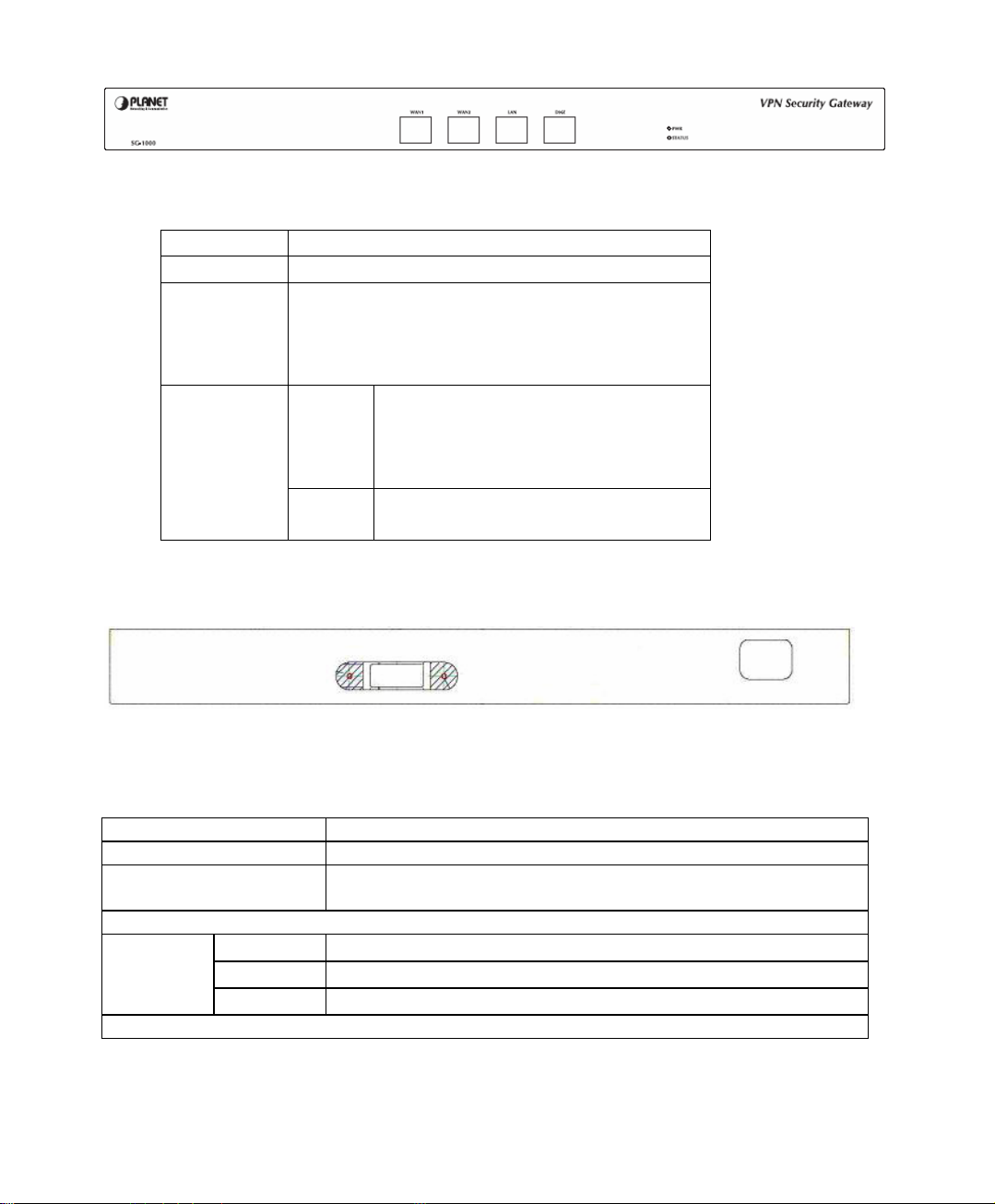
1.2 Front View
- LED definition
LED Description
PWR Power is supplied to this device.
STATUS Blinks to indicate this devise is being turned
WAN1,
WAN2,
LAN, DMZ
1.3 Rear View
on and booting. After one minute, this LED
indicator will stop blinking, it means this
device is now ready to use.
Green Steady on indicates the port is
connected to other network device.
Blink to indicates there is traffic on
the port
Orange Steady on indicates the port is
connected at 100Mbps speed
1.4 Specification
Product VPN Security Gateway
Model SG-1000
Recommend concurrent
30 ~ 50
user
Hardware
Ethernet
LAN
WAN
DMZ
1 x 10/100 Based-TX RJ-45
2 x 10/100 Based-TX RJ-45
1 x 10/100 Based-TX RJ-45
Software
8
Page 10

Management
Network Connection
Routing Mode
Concurrent Sessions
New session / second
WAN to LAN
Throughput
VPN Throughput
VPN 3DES Throughput
VPN Function
SSL VPN
IPSec VPN Trunk
VPN Connection
Tunnels / Allow to
Configure
Content Filtering
Firewall
QoS
User authentication
Logs
Accounting Report
Statistics
Others
Web
Transparent mode, NAT, Multi-NAT
Static Route, RIPv2
110,000
10,000
100Mbps
18Mbps
17Mbps
SSL, IPSec, PPTP server and client
DES, 3DES, and AES encrypting
SHA-1 / MD5 authentication algorithm
Remote access VPN (Client-to-Site) and Site to Site VPN
VPN Trunk
Internal Subnet of Server: 10
Connection Tunnels: 50
50
IPSec: 100 / 200
PPTP Serve: 32 / 32
PPTP Client: 16 / 16
URL Blocking
Blocks Popup, Java Applet, cookies and Active X
P2P Application Blocking
Instant Message Blocking
Download Blocking
Policy-based Firewall rule with schedule
NAT/ NAPT, SPI Firewall
Policy-based bandwidth management
Guarantee and maximum bandwidth with 3 priority levels
Classify traffics based on IP, IP subnet, TCP/UDP port
Built-in user database with up to 200 entries
Support local database, RADIUS and POP3 authentication
Log and alarm for event and traffic
Log can be saved from web, sent by e-mail or sent to syslog
server
Record inbound and outbound traffic’s utilization by Source
IP, Destination IP and Service
Traffic statistic for WAN interface and policies
Graphic display
Dynamic DNS, NTP, DHCP server, Virtual server,
9
Page 11

Chapter 2
Administration
“System” is the managing of settings such as the privileges of packets that pass through
the SG-1000 and monitoring controls. The System Administrators can manage, monitor,
and configure SG-1000 settings. But all configurations are “read-only” for all users
other than the System Administrator; those users are not able to change any setting of
the SG-1000.
10
Page 12

Define the required fields of Administrator
Administrator Name:
The username of Administrators and Sub Administrator for the SG-1000. The
admin user name cannot be removed; and the sub-admin user can be removed or
configure.
The default Account: admin; Password: admin
Privilege:
The privileges of Administrators (Admin or Sub Admin). The username of the
main Administrator is Administrator with reading / writing privilege.
Administrator also can change the system setting, log system status, and to increase
or delete sub-administrator. Sub-Admin may be created by the Admin by clicking
New Sub Admin
. Sub Admin have only read and monitor privilege and cannot
change any system setting value.
Configure:
Click Modify to change the “Sub-Administrator’s” password or click Remove to
delete a “Sub Administrator.”
11
Page 13
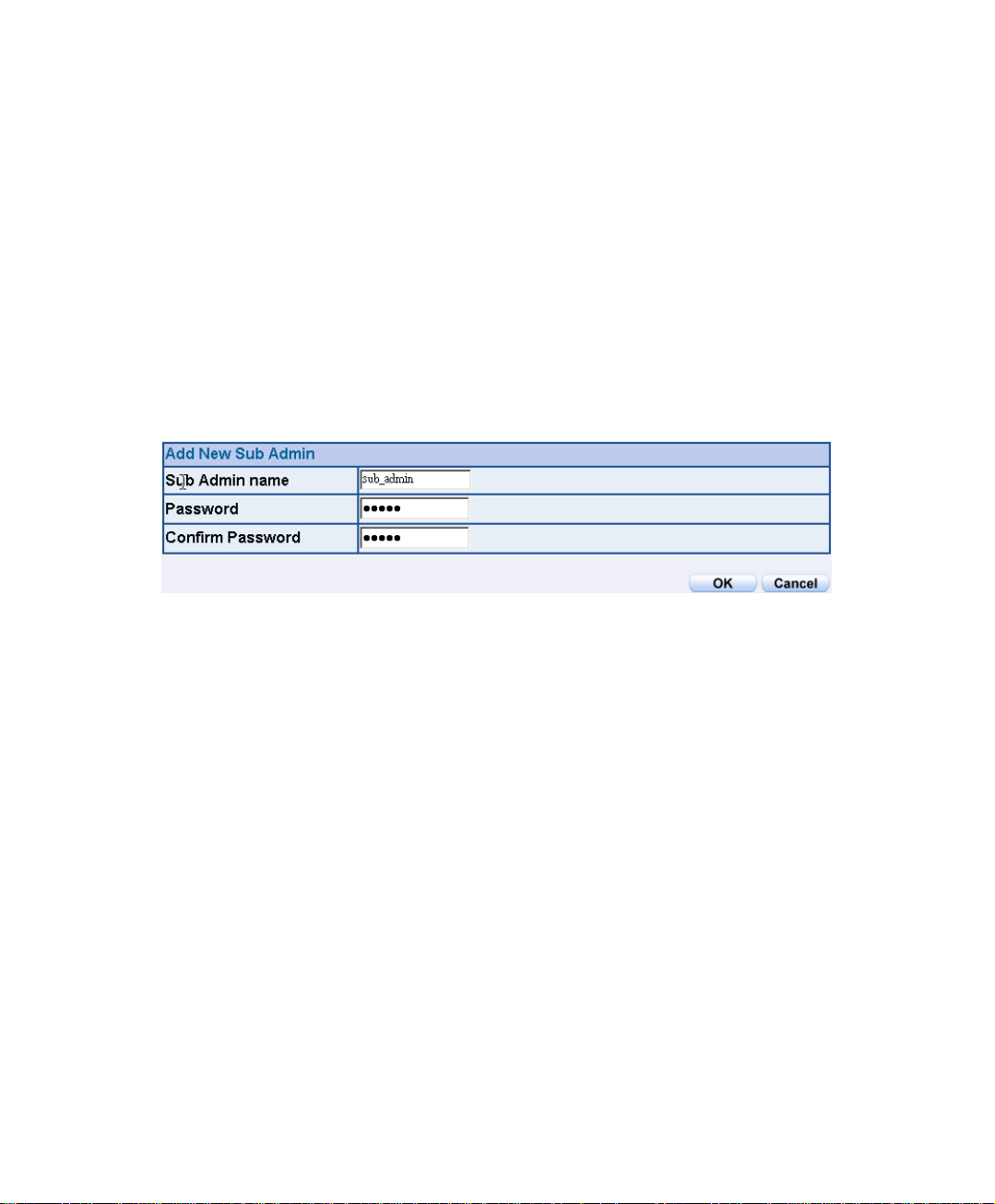
2.1 Adding a new Sub Administrator
STEP 1﹒In the Admin Web UI, click the New Sub Admin button to create a new
Sub Administrator.
STEP 2﹒In the Add New Sub Administrator Web UI and enter the following setting:
Sub Admin Name: sub_admin
Password: 12345
Confirm Password: 12345
STEP 3﹒Click OK to a
dd the user or click Cancel to cancel it.
Add New Sub Admin
12
Page 14
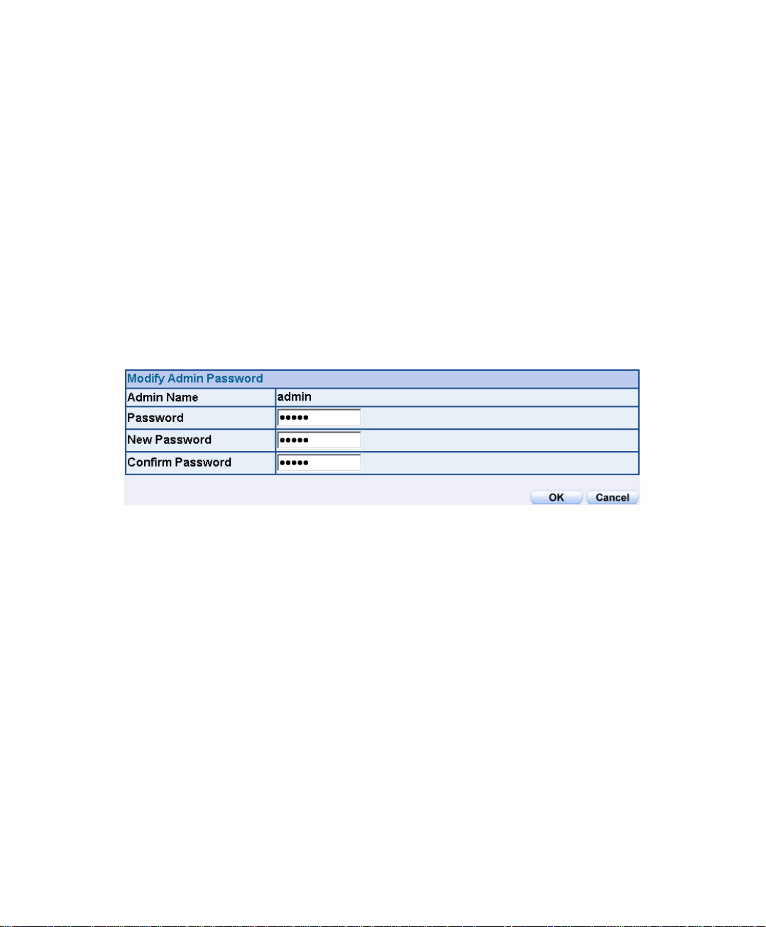
Modify the Administrator’s Password
STEP 1﹒In the Admin Web UI, locate the Administrator name you want to edit, and
click on Modify in the Configure field.
STEP 2﹒The Modify Administrator Password Web UI will appear. Enter the
following information:
Password: admin
New Password: 52364
Confirm Password: 52364
STEP 3﹒Click OK to confirm password change.
Modify Admin Password
13
Page 15
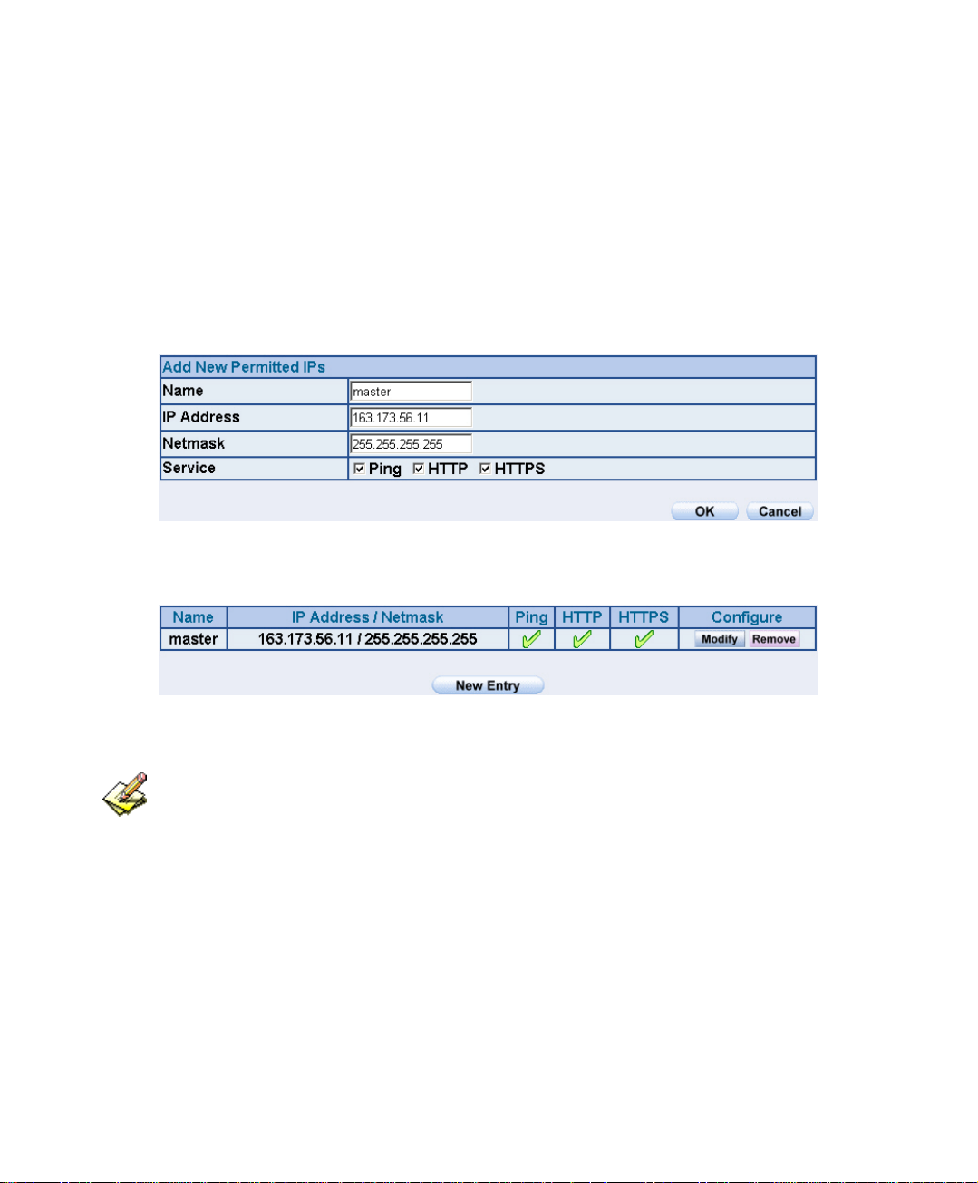
2.2 Add Permitted IPs
STEP 1﹒Add the following setting in Permitted IPs of Administration:
Name: Enter master
IP Address: Enter 163.173.56.11
Netmask: Enter 255.255.255.255
Service: Select Ping, HTTP, and HTTPS.
Click OK
Complete add new permitted IPs
Setting Permitted IPs Web UI
Complete Add New Permitted Ips
To make Permitted IPs be effective, it must cancel the Ping, HTTP, and HTTPS
selection in the Web UI of SG-1000 that Administrator enter. (LAN, WAN, or DMZ Interface)
Before canceling the HTTP and HTTPS selection of Interface, must set up the Permitted IPs
first, otherwise, it would cause the situation of cannot enter Web UI by appointed Interface.
14
Page 16
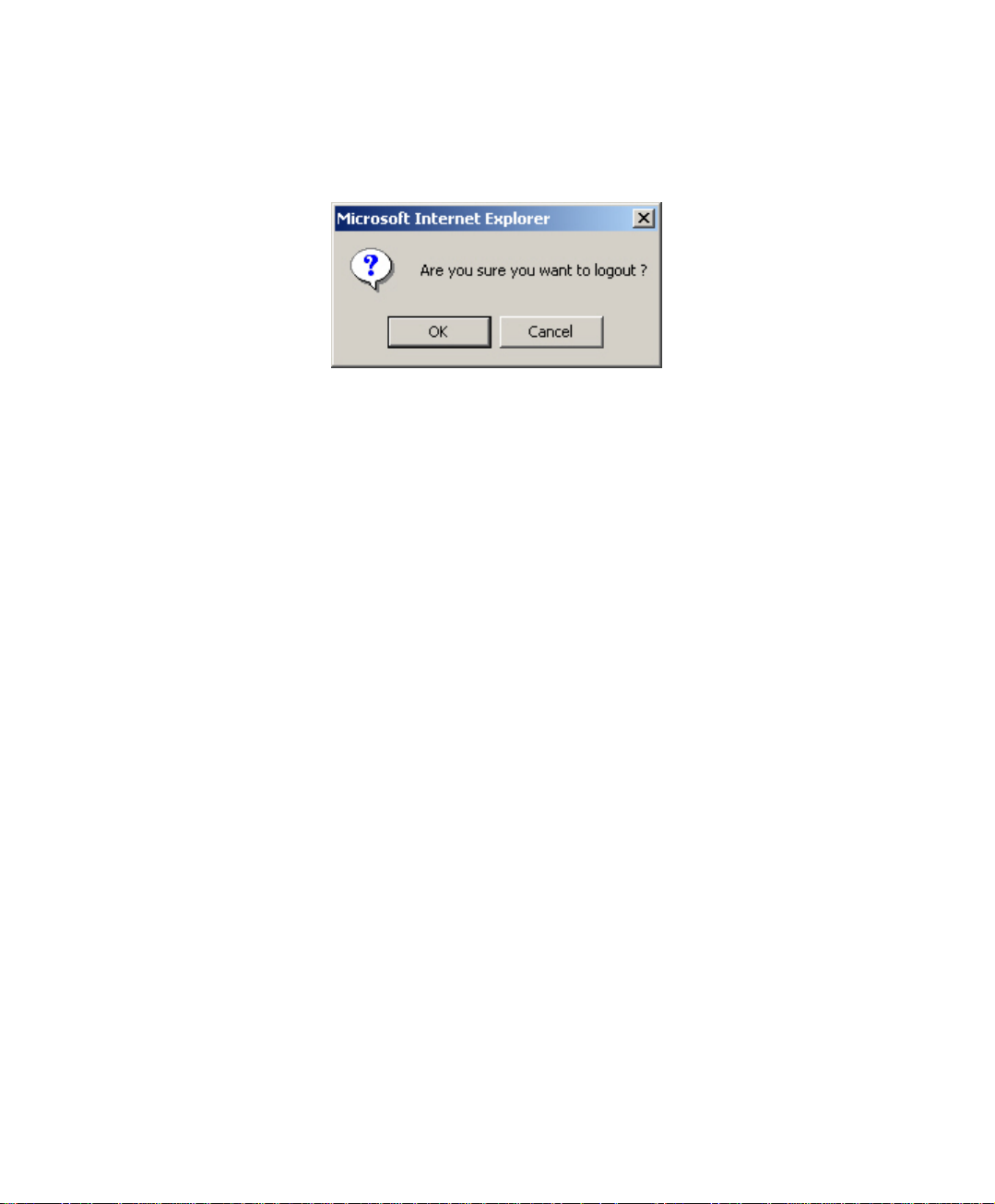
2.3 Logout
STEP 1﹒Click Logout which locate in Browser’s above right to protect the system
while Administrator are away.
Confirm Logout Web UI
15
Page 17
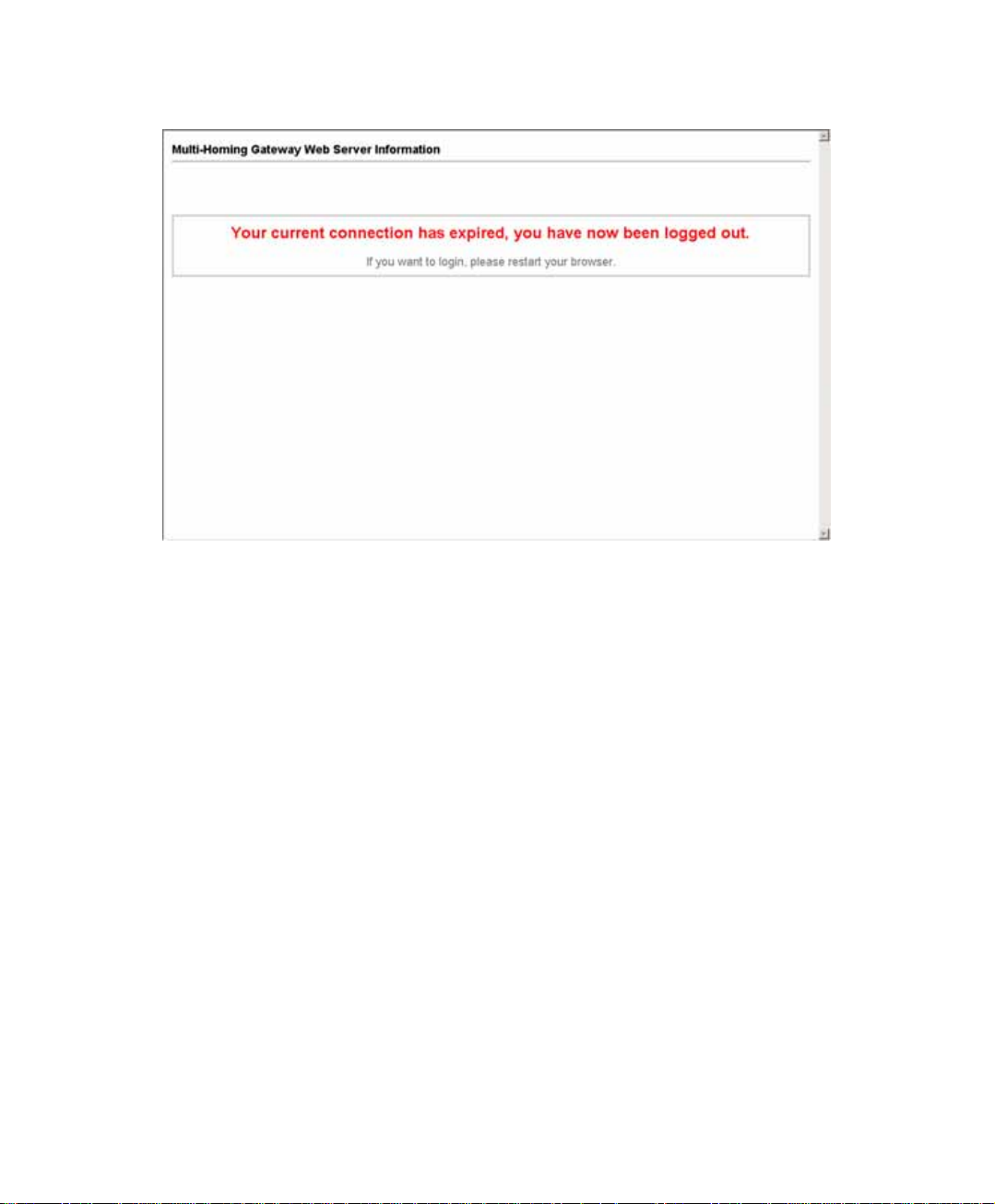
STEP 2﹒Click OK and the logout message will appear in Web UI.
Logout Web UI Message
16
Page 18

2.4 Software Update
STEP 1﹒Select Software Update in System, and follow the steps below:
To obtain the version number from Version Number and obtain the
latest version from Internet. And save the latest version in the hardware
of the PC, which manage the SG-1000
Click Browse and choose the latest software version file.
Click OK and the system will update automatically.
It takes 3 minutes to update software. The system will reboot after update. During the
updating time, please don’t turn off the PC or leave the Web UI. It may cause some unexpected
mistakes. (Strong suggests updating the software from LAN to avoid unexpected mistakes.)
17
Page 19

Chapter 3
Configure
The Configure is according to the basic setting of the SG-1000. In this chapter the
definition is Setting, Date/Time, Multiple Subnet, Route Table, DHCP, Dynamic DNS,
Hosts Table, and Language settings.
18
Page 20

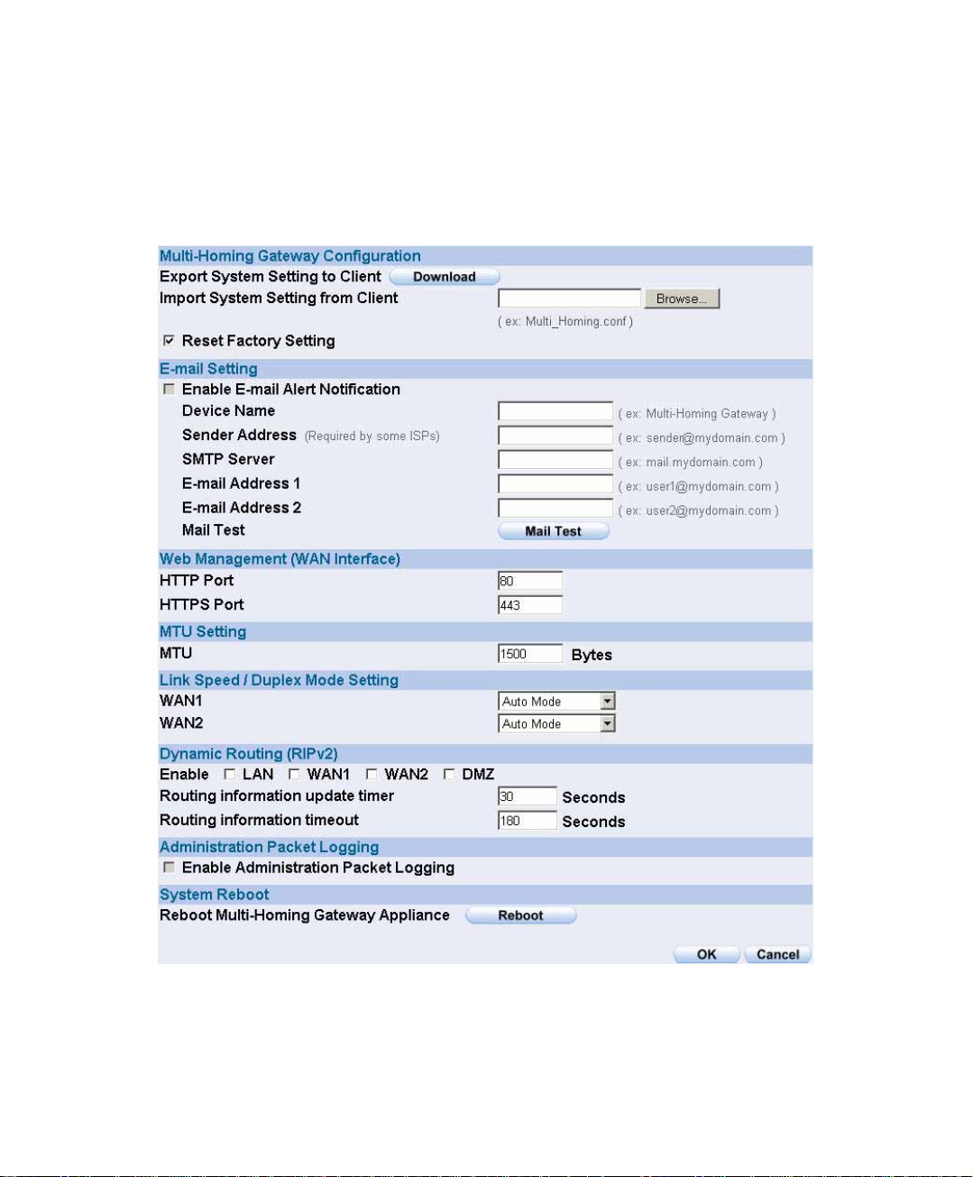
Define the required fields of Settings
SG-1000 Configuration:
The Administrator can import or export the system settings. Click OK to import
the file into the SG-1000 or click Cancel to cancel importing. You also can revive
to default value here.
Email Settings:
Select Enable E-mail Alert Notification under E-mail Settings. This function will
enable the SG-1000 to send e-mail alerts to the System Administrator when the
network is being attacked by hackers or when emergency conditions occur. (It can
be set from Settings-Hacker Alert in System to detect Hacker Attacks)
Web Management (WAN Interface):
The System Manager can change the port number used by HTTP port anytime.
(Remote Web UI management)
After HTTP port has changed, if the administrator want to enter Web UI from WAN, will
have to change the port number of browser. (For example: http://61.62.108.172:8080)
MTU Setting:
It provides the Administrator to modify the networking package length anytime. Its
default value is 1500 Bytes.
Link Speed / Duplex Mode:
By this function can set the transmission speed and mode of WAN Port when
connecting other device.
19
Page 21

Administration Packet Logging:
After enable this function; the SG-1000 will record packet which source IP or
destination address is SG-1000. And record in Traffic Log for System Manager to
inquire about.
Define the required fields of Time Settings
Synchronize Time/Date:
Synchronizing the SG-1000 with the System Clock. The administrator can
configure the SG-1000’s date and time by either syncing to an Internet Network
Time Server (NTP) or by syncing to your computer’s clock.
GMT:
International Standard Time (Greenwich Mean Time)
Define the required fields of Multiple Subnet
Forwarding Mode:
To display the mode that Multiple Subnet use. (NAT mode or Routing Mode)
WAN Interface Address:
The IP address that Multiple Subnet corresponds to WAN.
LAN Interface Address/Subnet Netmask:
The Multiple Subnet range
20
Page 22

NAT Mode:
It allows Internal Network to set multiple subnet address and connect with the
Internet through different WAN IP Addresses. For example:The lease line of a
company applies several real IP Addresses 168.85.88.0/24, and the company is
divided into R&D department, service, sales department, procurement department,
accounting department, the company can distinguish each department by different
subnet for the purpose of managing conveniently. The settings are as the
following:
1. R&D department subnet:192.168.1.1/24(LAN) ÅÆ 168.85.88.253(WAN)
2. Service department subnet: 192.168.2.1/24(LAN) ÅÆ 168.85.88.252(WAN)
3. Sales department subnet: 192.168.3.1/24(LAN) ÅÆ 168.85.88.251(WAN)
4. Procurement department subnet
192.168.4.1/24(LAN) ÅÆ 168.85.88.250(WAN)
5. Accounting department subnet
192.168.5.1/24(LAN) ÅÆ 168.85.88.249(WAN)
The first department (R&D department) had set while setting interface IP; the other four
ones have to be added in Multiple Subnet. After completing the settings, each
department uses the different WAN IP Address to connect to the Internet. The settings
of each department are as following:
Service Sales Procurement Accounting
IP Address 192.168.2.2~254 192.168.3.2~254 192.168.4.2~254 192.168.5.2~254
Subnet Netmask 255.255.255.0 255.255.255.0 255.255.255.0 255.255.255.0
Gateway 192.168.2.1 192.168.3.1 192.168.4.1 192.168.5.1
Routing Mode:
It is the same as NAT mode approximately but does not have to correspond to the
real WAN IP address, which let internal PC to access to Internet by its own IP.
(External user also can use the IP to connect with the Internet)
21
Page 23

Define the required fields of DHCP
Subnet:
The domain name of LAN
NetMask:
The LAN Netmask
Gateway:
The default Gateway IP address of LAN
Broadcast IP:
The Broadcast IP of LAN
Define the required fields of DDNS
Domain Name:
The domain name that provided by DDNS
WAN IP Address:
The WAN IP Address, which the domain name corresponds to.
Define the required fields of Host T able
Domain Name:
It can be set by System Manager. To let the internal user to access to the
information that provided by the host by this domain name
Virtual IP Address:
The virtual IP address respective to Host Table. It must be LAN or DMZ IP
address.
22
Page 24
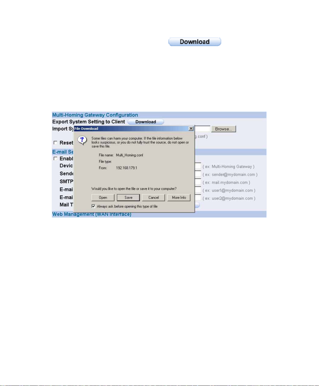
System Settings- Exporting
STEP 1﹒In System Setting Web UI, click on button next to Export
System Settings to Client.
STEP 2﹒When the File Download pop-up window appears, choose the destination
place where to save the exported file and click on Save. The setting value of
SG-1000 will copy to the appointed site instantly.
Select the Destination Place to Save the Exported File
23
Page 25
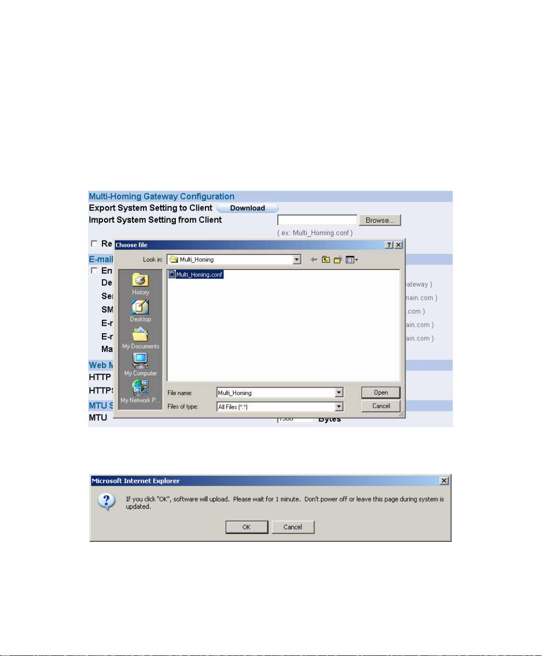
3.1 System Settings- Importing
STEP 1﹒In System Setting Web UI, click on the Browse button next to Import
System Settings from Client. When the Choose File pop-up window
appears, select the file to which contains the saved SG-1000 Settings, then
click OK.
STEP 2﹒Click OK to import the file into the SG-1000
Enter the File Name and Destination of the Imported File
Upload the Setting File Web UI
24
Page 26
Restoring Factory Default Settings
STEP 1﹒Select Reset Factory Settings in SG-1000 Configuration Web UI
STEP 2﹒Click OK at the bottom-right of the page to restore the factory settings.
Reset Factory Settings
25
Page 27
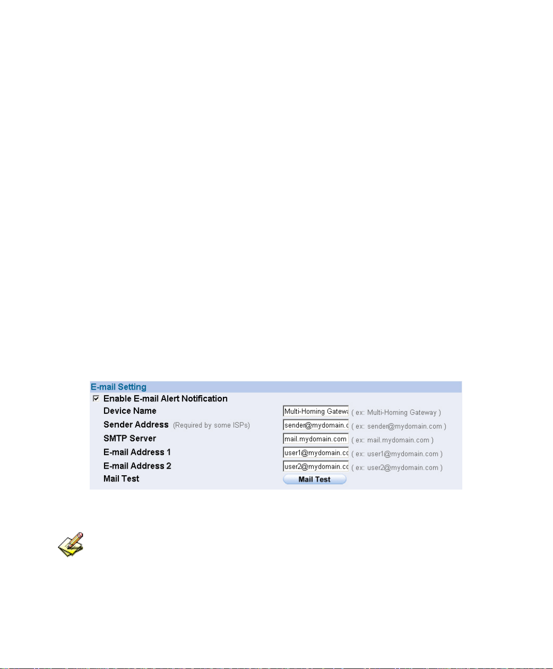
Enabling E-mail Alert Notification
STEP 1﹒Select Enable E-mail Alert Notification under E-Mail Settings.
STEP 2﹒Device Name: Enter the Device Name or use the default value.
STEP 3﹒Sender Address: Enter the Sender Address. (Required by some ISPs.)
STEP 4﹒SMTP Server IP: Enter SMTP server’s IP address.
STEP 5﹒E-Mail Address 1: Enter the e-mail address of the first user to be notified.
STEP 6﹒E-Mail Address 2: Enter the e-mail address of the second user to be notified.
(Optional)
STEP 7﹒Click OK on the bottom-right of the screen to enable E-mail Alert
Notification.
Enable E-mail Alert Notification
Click on Mail Test to test if E-mail Address 1 and E-mail Address 2 can receive the Alert
Notification correctly.
26
Page 28
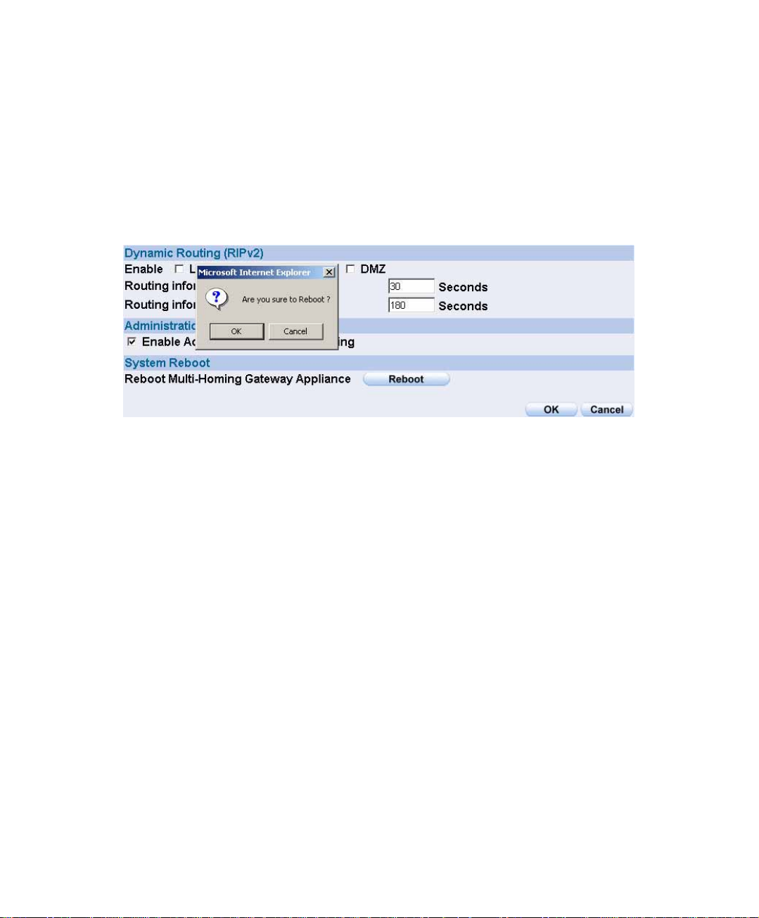
Reboot SG-1000
STEP 1﹒Reboot SG-1000:Click Reboot button next to Reboot SG-1000 Appliance.
STEP 2﹒A confirmation pop-up page will appear.
STEP 3﹒Follow the confirmation pop-up page; click OK to restart SG-1000.
Reboot SG-1000
27
Page 29
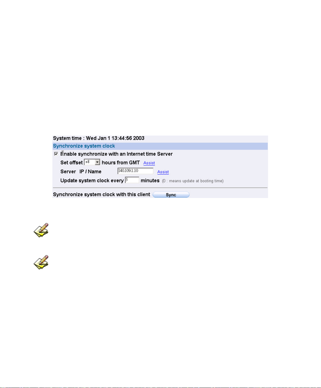
3.2 Date/Time Settings
STEP 1﹒Select Enable synchronize with an Internet time Server
STEP 2﹒Click the down arrow to select the offset time from GMT.
STEP 3﹒Enter the Server IP / Name with which you want to synchronize.
STEP 4﹒Set the interval time to synchronize with outside servers.
System Time Setting
Click on the Sync button and then the SG-1000’s date and time will be synchronized to the
Administrator’s PC.
The value of Set Offset From GMT and Server IP / Name can be looking for from
Assist.
28
Page 30

3.3 Multiple Subnet
Connect to the Internet through Multiple Subnet NAT or Routing Mode by the IP
address that set by the LAN user’s network card
Preparation
SG-1000 WAN1 (10.10.10.1) connect to the ISP Router (10.10.10.2) and the subnet that
provided by ISP is 162.172.50.0/24
To connect to Internet, WAN2 IP (211.22.22.22) connects with ATUR.
29
Page 31

Adding Multiple Subnet
Add the following settings in Multiple Subnet of System function:
Click on New Entry
Alias IP of LAN Interface: Enter 162.172.50.1
Netmask:Enter 255.255.255.0
WAN1: Enter Interface IP 10.10.10.1, and choose Routing in
Forwarding Mode
WAN2:Enter Interface IP 211.22.22.22, and choose NAT in
Forwarding Mode
Click OK
Complete Adding Multiple Subnet
Add Multiple Subnet Web UI
30
Page 32

WAN1 and WAN2 Interface can use Assist to enter the data.
After setting, there will be two subnet in LAN: 192.168.1.0/24 (default LAN subnet) and
162.172.50.0/24. So if LAN IP is:
˙192.168.1.xx, it must use NAT Mode to access to the Internet. (In Policy it only can setup to
access to Internet by WAN2. If by WAN1 Routing mode, then it cannot access to Internet by its
virtual IP)
˙162.172.50.xx, it uses Routing mode through WAN1 (The Internet Server can see your IP
162.172.50.xx directly). And uses NAT mode through WAN2 (The Internet Server can see your
IP as WAN2 IP)
Multiple Subnet Network
31
Page 33

The SG-1000’s Interface Status:
WAN1 IP: 10.10.10.1
WAN2 IP:211.22.22.22
LAN Port IP:192.168.1.1
LAN Port Multiple Subnet:162.172.50.1
32
Page 34

3.4 Route Table
To connect two different subnet router with the SG-1000 and makes them to connect to
Internet through SG-1000.
Preparation
Company A: WAN1 (61.11.11.11) connects with ATUR to Internet
WAN2 (211.22.22.22) connects with ATUR to Internet
LAN subnet: 192.168.1.1/24
The Router1 which connect with LAN (10.10.10.1, support RIPv2) its LAN subnet is
192.168.10.1/24
Company B: Router2 (10.10.10.2, support RIPv2), its LAN subnet is 192.168.20.1/24
Company A ‘s Router1 (10.10.10.1) connect directly with Company B ‘s Router2
(10.10.10.2).
33
Page 35

Route Table
STEP 1﹒Enter the following settings in Route Table in System function:
【Destination IP】: Enter 192.168.10.1
【Netmask】: Enter 255.255.255.0。
【Gateway】: Enter 192.168.1.252
【Interface】: Select LAN
Click OK
Add New Static Route1
STEP 2﹒Enter the following settings in Route Table in System function:
【Destination IP】: Enter 192.168.20.1
【Netmask】: Enter 255.255.255.0
【Gateway】: Enter 192.168.1.252
【Interface】: Select LAN
Click OK
Add New Static Route2
34
Page 36

STEP 3﹒Enter the following setting in Route Table in System function:
【Destination IP】: Enter 10.10.10.0
【Netmask】: Enter 255.255.255.0
【Gateway】: Enter 192.168.1.252
【Interface】: Select LAN
Click OK
Add New Static Route3
35
Page 37

STEP 4﹒Adding successful. At this time the computer of 192.168.10.1/24,
192.168.20.1/24 and 192.168.1.1/24 can connect with each other and
connect to Internet by NAT.
Route Table Setting
36
Page 38

3.5 DHCP
STEP 1﹒Select DHCP in System and enter the following settings:
Domain Name:Enter the Domain Name
DNS Server 1: Enter the distributed IP address of DNS Server1.
DNS Server 2: Enter the distributed IP address of DNS Server2.
WINS Server 1: Enter the distributed IP address of WINS Server1.
WINS Server 2: Enter the distributed IP address of WINS Server2.
LAN Interface:
Client IP Address Range 1: Enter the starting and the ending IP
address dynamically assigning to DHCP clients. The default value
is 192.168.1.2 to 192.168.1.254 (it must be in the same subnet)
Client IP Address Range 2: Enter the starting and the ending IP
address dynamically assigning to DHCP clients. But it must in the
same subnet as Client IP Address Range 1 and the range cannot be
repeated.
DMZ Interface: the same as LAN Interface. (DMZ works only if to enable
DMZ Interface)
Leased Time: Enter the leased time for Dynamic IP. The default time is 24
hours.
Click OK and DHCP setting is completed.
37
Page 39
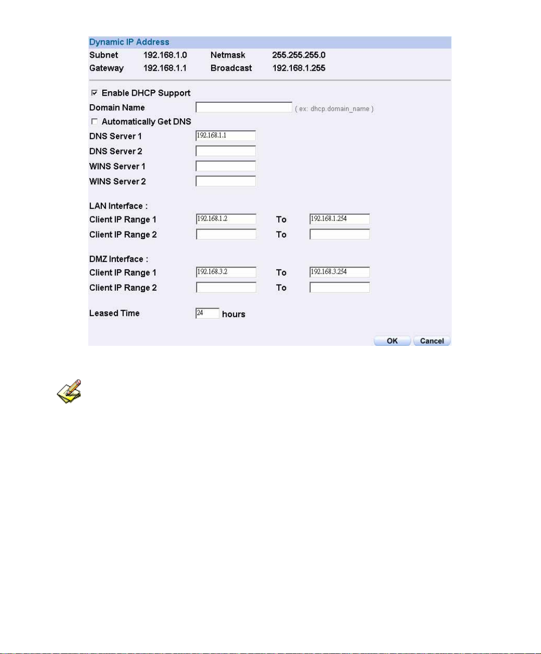
DHCP Web UI
When selecting Automatically Get DNS, the DNS Server will lock it as LAN Interface IP.
(Using Occasion: When the system Administrator starts Authentication, the users’ first DNS
Server must be the same as LAN Interface IP in order to enter Authentication Web UI)
38
Page 40

3.6 Dynamic DNS Settings
STEP 1﹒Select Dynamic DNS in System function. Click New Entry button
Service providers:Select service providers.
Automatically fill in the WAN 1/2 IP:Check to automatically fill in
the WAN 1/2 IP.。
User Name:Enter the registered user name.
Password:Enter the password
Domain name:Enter Your host domain name
Click OK to add Dynamic DNS.
DDNS Web UI
Complete DDNS Setting
39
Page 41

Chart
Meaning Update
successfully
Incorrect
username or
Connecting
Unknown error
to server
password
If System Administrator had not registered a DDNS account, click on Sign up then can
enter the website of the provider.
If you do not select Automatically fill in the WAN IP and then you can enter a specific
IP in WAN IP. Let DDNS to correspond to that specific IP address.
40
Page 42

3.7 Host T able
y STEP 1﹒Select Host Table in Settings function and click on New Entr
Domain Name: The domain name of the server
Virtual IP Address:
Click OK to add Host Table.
To use Host Table, the user PC’s first DNS Server must be the same as the LAN Port or
DMZ Port IP of SG-1000. That is, the default gateway.
The virtual IP address respective to Host Table
Add New Host Table
41
Page 43

3.8 Language
Select the Language version (English Version/ Traditional Chinese Version or
Simplified Chinese Version) and click OK.
Language Setting Web UI
42
Page 44

Chapter 4
Interface
In this section, the Administrator can set up the IP addresses for the office network.
The Administrator may configure the IP addresses of the LAN network, the WAN 1/2
network, and the DMZ network. The netmask and gateway IP addresses are also
configured in this section.
43
Page 45

Define the required fields of Interface
LAN:
Using the LAN Interface, the Administrator can set up the LAN network of SG-
1000.
Ping:
Select this function to allow the user to ping the Interface IP Address.
HTTP:
Select to enable the user to enter the Web UI of SG-1000 from Interface IP through
HTTP protocol.
HTTPS:
Select to enable the user to enter the Web UI of SG-1000 from Interface IP through
HTTPS protocol.
WAN:
The System Administrator can set up the WAN network of SG-1000.
Balance Mode:
Auto: The SG-1000 will adjust the WAN 1/2 utility rate automatically according
to the downstream/upstream of WAN. (For users who are using various download
bandwidth)
Round-Robin: The SG-1000 distributes the WAN 1/2 download bandwidth 1:1, in
other words, it selects the agent by order. (For users who are using same download
bandwidths)
By Traffic: The SG-1000 distributes the WAN 1/2 download bandwidth by
accumulative traffic.
By Session: The SG-1000 distributes the WAN 1/2 download bandwidth by
saturated connections.
By Packet: The SG-1000 distributes the WAN 1/2 download bandwidth by
accumulated packets and saturated connection.
44
Page 46

Connect Mode:
Display the current connection mode:
PPPoE (ADSL user)
Dynamic IP Address (Cable Modem User)
Static IP Address
Saturated Connections:
Set the number for saturation whenever session numbers reach it, the SG-1000
switches to the next agent on the list.
Priority:
Set priority of WAN for Internet Access.
Connection Test:
To test if the WAN network can connect to Internet or not. The testing ways are as
following:
ICMP:To test if the connection is successful or not by the Ping IP you set.
DNS:To test if the connection is successful or not by checking Domain
Name.
Upstream/Downstream Bandwidth:
The System Administrator can set up the correct Bandwidth of WAN network
Interface here.
Auto Disconnect:
The PPPoE connection will automatically disconnect after a length of idle time (no
activities). Enter the amount of idle time before disconnection in the field. Enter
“0” if you do not want the PPPoE connection to disconnect at all.
45
Page 47

DMZ:
The Administrator uses the DMZ Interface to set up the DMZ network.
The DMZ includes:
NAT Mode:In this mode, the DMZ is an independent virtual subnet. This
virtual subnet can be set by the Administrator but cannot be the same as LAN
Interface.
Transparent Mode: In this mode, the DMZ and WAN Interface are in the
same subnet.
46
Page 48

We set up four Interface Address examples in this chapter:
No. Suitable
Example
Situation
Ex1
Ex2
Ex3
Ex4
LAN
WAN
DMZ
DMZ
Modify LAN Interface Settings
Setting WAN Interface Address
Setting DMZ Interface Address (NAT Mode)
Setting DMZ Interface Address (Transparent Mode)
47
Page 49

4.1 Modify LAN Interface Settings
STEP 1﹒Select LAN in Interface and enter the following setting:
Enter the new IP Address and Netmask
Select Ping, HTTP, and HTTPS.
Click OK
Setting LAN Interface Web UI
The default LAN IP Address is 192.168.1.1. After the Administrator setting the new LAN
IP Address on the computer , he/she have to restart the System to make the new IP address
effective. (when the computer obtain IP by DHCP)
Do not cancel Web UI selection before not setting Permitted IPs yet. It will cause the
Administrator cannot be allowed to enter the SG-1000’s Web UI from LAN.
48
Page 50

4.2 Setting WAN Interface Address
STEP 1﹒Select WAN in Interface and click Modify in WAN1 Interface.
The setting of WAN2 Interface is almost the same as WAN1. The difference is that W
has a selection of Disable. The System Administrator can close WAN2 Interface by this
selection.
Disable WAN2 Interface
AN2
49
Page 51

STEP 2﹒Setting the Connection Service (ICMP or DNS way):
ICMP:Enter an Alive Indicator Site IP (can select from Assist)
DNS:Enter DNS Server IP Address and Domain Name (can select
from Assist)
Setting time of seconds between sending alive packet.
ICMP Connection
DNS Service
Connection test is used for SG-1000 to detect if the WAN can connect or not. So the
Alive Indicator Site IP, DNS Server IP Address, or Domain Name must be able to use
permanently. Or it will cause judgmental mistakes of the device.
50
Page 52

STEP 3﹒Select the Connecting way:
PPPoE (ADSL User):
1. Select PPPoE
2. Enter User Name as an account
3. Enter Password as the password
4. Select Dynamic or Fixed in IP Address provided by ISP. If you
select Fixed, please enter IP Address, Netmask, and Default Gateway.
5. Enter Max. Downstream Bandwidth and Max. Upstream
Bandwidth. (According to the flow that user apply)
6. Select Ping, HTTP, and HTTPS.
7. Click OK
51
Page 53
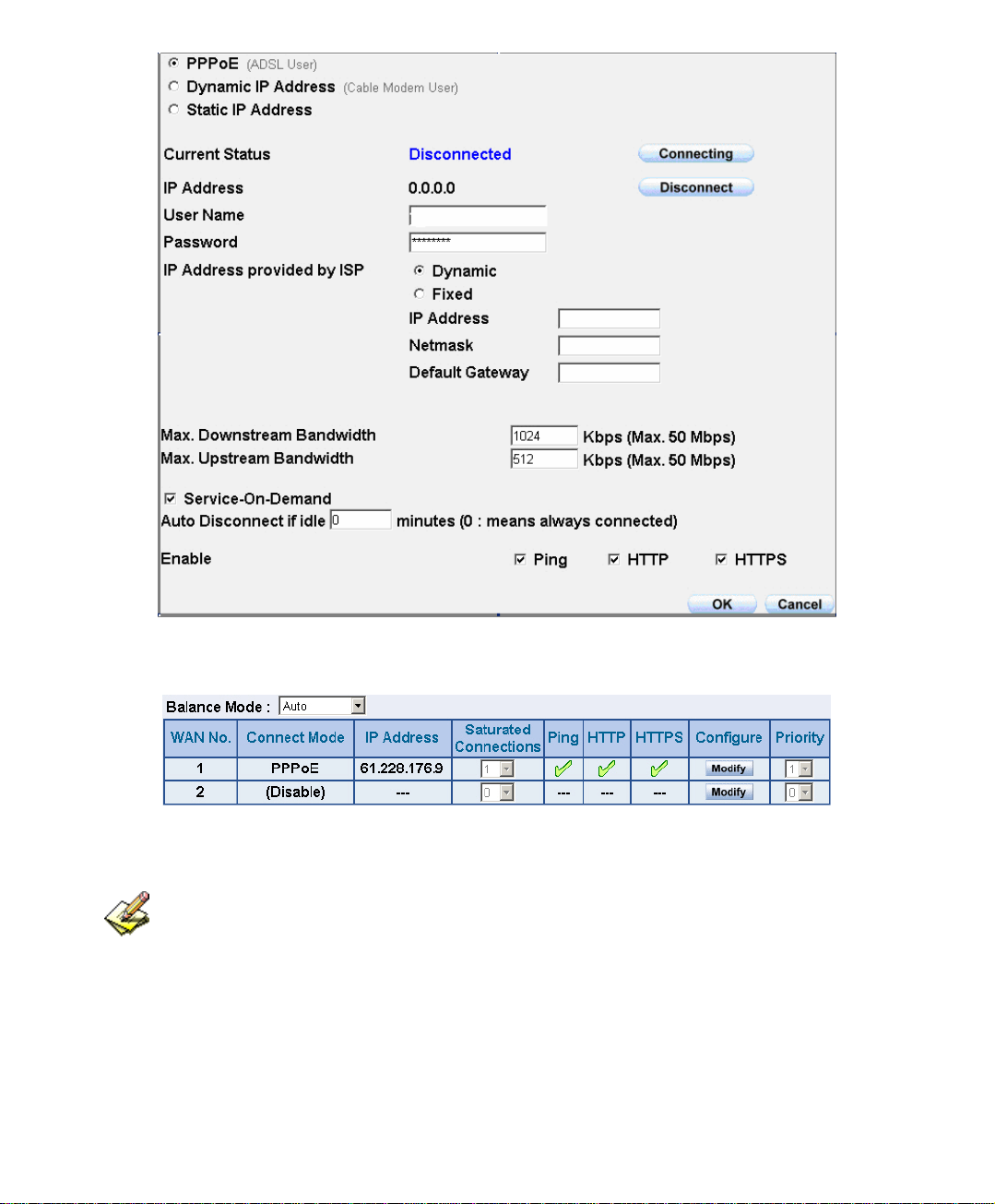
PPPoE Connection
Complete PPPoE Connection Setting
If the connection is PPPoE, you can choose Service-On-Demand for WAN Interface to
connect automatically when disconnect; or to set up Auto Disconnect if idle (not recommend)
52
Page 54

Dynamic IP Address (Cable Modem User):
1. Select Dynamic IP Address (Cable Modem User)
2. Click Renew in the right side of IP Address and then can obtain IP
automatically.
3. If the MAC Address is required for ISP then click on Clone MAC
Address to obtain MAC IP automatically.
4. Hostname: Enter the hostname provided by ISP.
5. Domain Name: Enter the domain name provided by ISP.
6. User Name and Password are the IP distribution method according to
Authentication way of DHCP+ protocol (like ISP in China)
7. Enter Max. Downstream Bandwidth and Max. Upstream
Bandwidth (According to the flow that user apply)
8. Select Ping, HTTP, and HTTPS.
9. Click OK
Dynamic IP Address Connection
53
Page 55

Complete Dynamic IP Connection Setting
54
Page 56

Static IP Address
1. Select Static IP Address
2. Enter IP Address, Netmask, and Default Gateway that provided by
ISP
3. Enter DNS Server1 and DNS Server2
In WAN2, the connecting of Static IP Address does not need to set DNS Server
4. Enter Max. Downstream Bandwidth and Max. Upstream
Bandwidth (According to the flow that user apply)
5. Select Ping, HTTP, and HTTPS.
6. Click OK
Static IP Address Connection
55
Page 57

Complete Static IP Address Connection Setting
When selecting Ping and Web UI on WAN network Interface, users will be able to ping
the SG-1000 and enter the Web UI WAN network. It may influence network security. The
suggestion is to Cancel Ping and Web UI after all the settings have finished. And if the System
Administrator needs to enter UI from WAN, he/she can use Permitted IPs to enter.
56
Page 58

4.3 Setting DMZ Interface Address (NAT Mode)
STEP 1﹒Click DMZ Interface
STEP 2﹒Select NAT Mode in DMZ Interface
Select NAT in DMZ Interface
Enter IP Address and Netmask
STEP 3﹒Select Ping, HTTP, and HTTPS.
STEP 4﹒Click OK
Setting DMZ Interface Address (NAT Mode) Web UI
57
Page 59

Setting DMZ Interface Address (Transparent Mode)
STEP 1﹒Select DMZ Interface
STEP 2﹒Select Transparent Mode in DMZ Interface
Select DMZ_Transparent in DMZ Interface
STEP 1﹒Select Ping, HTTP, and HTTPS.
STEP 2﹒Click OK
Setting DMZ Interface Address (Transparent Mode) Web UI
In WAN, the connecting way must be Static IP Address and can choose Transparent
Mode in DMZ.
58
Page 60

Chapter 5
Address
The SG-1000 allows the Administrator to set Interface addresses of the LAN network,
LAN network group, WAN network, WAN network group, DMZ and DMZ group.
An IP address in the Address Table can be an address of a computer or a sub network.
The Administrator can assign an easily recognized name to an IP address. Based on the
network it belongs to, an IP address can be an LAN IP address, WAN IP address or
DMZ IP address. If the Administrator needs to create a control policy for packets of
different IP addresses, he can first add a new group in the LAN Group or the WAN
Group and assign those IP addresses into the newly created group. Using group
addresses can greatly simplify the process of building control policies.
With easily recognized names of IP addresses and names of address groups shown in the
address table, the Administrator can use these names as the source address or destination
address of control policies. The address table should be setup before creating control policies, so
that the Administrator can pick the names of correct IP addresses from the address table when
setting up control policies.
59
Page 61

Define the required fields of Address
Name:
The System Administrator set up a name as IP Address that is easily recognized.
IP Address:
It can be a PC’s IP Address or several IP Address of Subnet. Different network area
can be: Internal IP Address, External IP Address, and DMZ IP Address.
Netmask:
When correspond to a specific IP, it should be set as: 255.255.255.255.
When correspond to several IP of a specific Domain. Take 192.168.100.1 (C Class
subnet) as an example, it should be set as: 255.255.255.0.
MAC Address:
Correspond a specific PC’s MAC Address to its IP; it can prevent users changing
IP and accessing to the net service through policy without authorizing.
Get Static IP address from DHCP Server:
When enable this function and then the IP obtain from DHCP Server automatically
under LAN or DMZ will be distributed to the IP that correspond to the MAC
Address.
60
Page 62

We set up two Address examples in this chapter:
No Suitable
Example
Situation
Ex1
LAN
Under DHCP circumstances, assign the specific IP to
static users and restrict them to access FTP net service
only through policy.
Ex2
LAN Group
WAN
Set up a policy that only allows partial users to connect
with specific IP (External Specific IP)
61
Page 63

5.1 Under DHCP situation, assign the specific IP to static users and
restrict them to access FTP net service only through policy
STEP 1﹒Select LAN in Address and enter the following settings:
Click New Entry button
Name: Enter Rayearth
IP Address: Enter 192.168.3.2
Netmask: Enter 255.255.255.255
MAC Address : Enter the user’s MAC Address(00:B0:18:25:F5:89)
Select Get static IP address from DHCP Server
Click OK
Setting LAN Address Book Web UI
Complete the Setting of LAN
62
Page 64

STEP 2﹒Adding the following setting in Outgoing Policy:
Add a Policy of Restricting the Specific IP to Access to Internet
STEP 3﹒Complete assigning the specific IP to static users in Outgoing Policy and
restrict them to access FTP net service only through policy:
Complete the Policy of Restricting the Specific IP to Access to Internet
63
Page 65

When the System Administrator setting the Address Book, he/she can choose the way of
clicking on
automatically.
to make the SG-1000 to fill out the user’s MAC Address
In LAN of Address function, the SG-1000 will default an Inside Any address represents
the whole LAN network automatically. Others like WAN, DMZ also have the Outside Any
and DMZ Any default address setting to represent the whole subnet.
The setting mode of WAN and DMZ of Address are the same as LAN; the only
difference is WAN cannot set up MAC Address.
64
Page 66

Setup a policy that only allows partial users to connect with specific IP
(External Specific IP)
STEP 1﹒Setting several LAN network Address.
Setting Several LAN Network Address
65
Page 67

STEP 2﹒Enter the following settings in LAN Group of Address:
Click New Entry
Enter the Name of the group
Select the users in the Available Address column and click Add
Click OK
Add New LAN Address Group
Complete Adding LAN Address Group
The setting mode of WAN Group and DMZ Group of Address are the same as LAN
Group.
66
Page 68

STEP 3﹒Enter the following settings in WAN of Address function:
Click New Entry
Enter the following data (Name, IP Address, Netmask)
Click OK
Add New WAN Address
Complete the Setting of WAN Address
67
Page 69

STEP 4﹒To exercise STEP1~3 in Policy
To Exercise Address Setting in Policy
Complete the Policy Setting
The Address function really take effect only if use with Policy.
68
Page 70

Chapter 6
Service
TCP and UDP protocols support varieties of services, and each service consists of a
TCP Port or UDP port number, such as TELNET (23), SMTP (21), SMTP (25), POP3
(110), etc. The SG-1000 includes two services: Pre-defined Service and Custom
Service.
The common-use services like TCP and UDP are defined in the Pre-defined Service and
cannot be modified or removed. In the custom menu, users can define other TCP port
and UDP port numbers that are not in the pre-defined menu according to their needs.
When defining custom services, the client port ranges from 1024 to 65535 and the
server port ranges from 0 to 65535
In this chapter, network services are defined and new network services can be added.
There are three sub menus under Service which are: Pre-defined, Custom, and Group.
The Administrator can simply follow the instructions below to define the protocols and
port numbers for network communication applications. Users then can connect to
servers and other computers through these available network services.
How to use Service?
The Administrator can add new service group names in the Group option under Service
menu, and assign desired services into that new group. Using service group the
Administrator can simplify the processes of setting up control policies. For example,
there are 10 different computers that want to access 5 different services on a server,
such as HTTP, FTP, SMTP, POP3, and TELNET. Without the help of service groups,
the Administrator needs to set up 50 (10x5) control policies, but by applying all 5
services to a single group name in the Service field, it takes only one control policy to
achieve the same effect as the 50 control policies.
69
Page 71

Define the required fields of Service
Pre-defined Web UI’s Chart and Illustration:
Chart Illustration
Any Service
TCP Service, For example: FTP, FINGER, HTTP, HTTPS ,
IMAP, SMTP, POP3, ANY, AOL, BGP, GOPHER, Inter Locator,
IRC, L2TP, LDAP, NetMeeting, NNTP, PPTP, Real Media,
RLOGIN, SSH, TCP ANY, TELNET, VDO Live, WAIS,
WINFRAME, X-WINDOWS, …etc.
UDP Service, For example:IKE, DNS, NTP, IRC, RIP, SNMP,
SYSLOG, TALK, TFTP, UDP-ANY, UUCP,…etc.
ICMP Service, Foe example:PING, TRACEROUTE…etc.
New Service Name:
The System Manager can name the custom service.
Protocol:
The protocol type to be used in connection for device, such as TCP and UDP mode
Client Port:
The port number of network card of clients. (The range is 1024~65535, suggest to
use the default range)
Server Port:
The port number of custom service
70
Page 72

We set up two Service examples in this chapter:
No Suitable
Example
Situation
Ex1
Custom
Allow external user to communicate with internal
user by VoIP through policy. (VoIP Port: TCP 1720,
TCP 15325-15333, UDP 15325-15333)
Ex2
Group
Setting service group and restrict the specific users
only can access to service resource that provided by
this group through policy. (Group: HTTP, POP3,
SMTP, DNS)
71
Page 73

6.1 Allow external user to communicate with internal user by VoIP
through policy. (VoIP Port: TCP 1720, TCP 15328-15333, UDP 15328-
15333)
STEP 1﹒Set LAN and LAN Group in Address function as follows:
Setting LAN Address Book Web UI
Setting LAN Group Address Book Web UI
72
Page 74

STEP 2﹒Enter the following setting in Custom of Service function:
Click New Entry
Service Name: Enter the preset name VoIP
Protocol#1 select TCP, need not to change the Client Port, and set the
Server Port as: 1720:1720
Protocol#2 select TCP, need not to change the Client Port, and set the
Server Port as: 15328:15333
Protocol#3 select UDP, need not to change the Client Port, and set the
Server Port as: 15328:15333
Click OK
Add User Define Service
Complete the Setting of User Define Service of VoIP
73
Page 75

Under general circumstances, the range of port number of client is 1024-65535. Change
the client range in Custom of is not suggested.
If the port numbers that enter in the two spaces are different port number, then enable the
port number under the range between the two different port numbers (for example:
15328:15333). And if the port number that enter in the two space are the same port number,
then enable the port number as one (for example: 1720:1720).
74
Page 76

STEP 3﹒Compare Service to Virtual Server.
Compare Service to Virtual Server
STEP 4﹒Compare Virtual Server to Incoming Policy. (Figure5-6)
Complete the Policy for External VoIP to Connect with Internal VoIP
STEP 5﹒In Outgoing Policy, complete the setting of internal users using VoIP to
connect with external network VoIP:
Complete the Policy for Internal VoIP to Connect with External VoIP
Service must cooperate with Policy and Virtual Server that the function can take effect
75
Page 77

6.2 Setting service group and restrict the specific users only can access
to service resource that provided by this group through policy (Group:
HTTP, POP3, SMTP, DNS)
STEP 1﹒Enter the following setting in Group of Service:
Click New Entry
Name: Enter Main_Service
Select HTTP, POP3, SMTP, DNS in Available Service and click Add
Click OK
Add Service Group
76
Page 78

Complete the setting of Adding Service Group
If you want to remove the service you choose from Selected Service, choose the service
you want to delete and click Remove.
77
Page 79

STEP 2﹒In LAN Group of Address function, Setting an Address Group that can
include the service of access to Internet.
Setting Address Book Group
STEP 3﹒Compare Service Group to Outgoing Policy.
Setting Policy
78
Page 80

Chapter 7
Schedule
In this chapter, the SG-1000 provides the Administrator to configure a schedule for
policy to take effect and allow the policies to be used at those designated times. And
then the Administrator can set the start time and stop time or VPN connection in Policy
or VPN. By using the Schedule function, the Administrator can save a lot of
management time and make the network system most effective.
How to use the Schedule?
The system Administrator can use schedule to set up the device to carry out the
connection of Policy or VPN during several different time division automatically.
79
Page 81

To configure the valid time periods for LAN users to access to Internet
in a day
STEP 1﹒Enter the following in Schedule:
Click New Entry
Enter Schedule Name
Set up the working time of Schedule for each day
Click OK
Setting Schedule Web UI
Complete the Setting of Schedule
80
Page 82

STEP 2﹒Compare Schedule with Outgoing Policy
Complete the Setting of Comparing Schedule with Policy
81
Page 83

Chapter 8
QoS
By configuring the QoS, you can control the OutBound and InBound
Upstream/Downstream Bandwidth. The administrator can configure the bandwidth
according to the WAN bandwidth.
Downstream Bandwidth:To configure the Guaranteed Bandwidth and Maximum
Bandwidth.
Upstream Bandwidth:To configure the Guaranteed Bandwidth and Maximum
Bandwidth.
QoS Priority:To configure the priority of distributing Upstream/Downstream and
unused bandwidth.
The SG-1000 configures the bandwidth by different QoS, and selects the suitable QoS
through Policy to control and efficiently distribute bandwidth. The SG-1000 also makes
it convenient for the administrator to make the Bandwidth to reach the best utility.
The Flow Before Using QoS
82
Page 84

The Flow After Using QoS (Max. Bandwidth: 400Kbps, Guaranteed Bandwidth: 200Kbps)
83
Page 85

Define the required fields of QoS
WAN:
Display WAN1 and WAN2
Downstream Bandwidth:
To configure the Guaranteed Bandwidth and Maximum Bandwidth according to
the bandwidth range you apply from ISP
Upstream Bandwidth:
To configure the Guaranteed Bandwidth and Maximum Bandwidth according to
the bandwidth range you apply from ISP
Priority:
To configure the priority of distributing Upstream/Downstream and unused
bandwidth.
Guaranteed Bandwidth:
The basic bandwidth of QoS. The connection that uses the IPSec Autokey of VPN
or Policy will preserve the basic bandwidth.
Maximum Bandwidth:
The maximum bandwidth of QoS. The connection that uses the IPSec Autokey of
VPN or Policy, which bandwidth will not exceed the amount you set.
84
Page 86

8.1 Setting a policy that can restrict the user’s downstream and
upstream bandwidth
STEP 1﹒Enter the following settings in QoS:
Click New Entry
Name: The name of the QoS you want to configure.
Enter the bandwidth in WAN1, WAN2
Select QoS Priority
Click OK
QoS Web UI Setting
Complete the QoS Setting
85
Page 87

STEP 2﹒Use the QoS that set by STEP1 in Outgoing Policy.
Setting the QoS in Policy
Complete Policy Setting
When the administrator are setting QoS, the bandwidth range that can be set is the value
that system administrator set in the WAN of Interface. So when the System Administrator sets
the downstream and upstream bandwidth in WAN of Interface, he/she must set up precisely.
86
Page 88

Chapter 9
Authentication
By configuring the Authentication, you can control the user’s (Internal user or remote
user who connect by VPN and IPSec) connection authority. The user has to pass the
authentication to access to Internet.
The SG-1000 configures the authentication of LAN’s user by setting account and
password to identify the privilege. Or by the RADIUS that set by yourself. The system
administrator can use this two mode to manage the Authentication.
87
Page 89

Define the required fields of Authentication
Authentication Management
Provide the Administrator the port number and valid time to setup SG-1000
authentication. (Have to setup the Authentication first)
Authentication Port: The internal user have to pass the authentication to
access to the Internet when enable SG-1000.
Re-Login if Idle: When the internal user access to Internet, can setup the idle
time after passing authentication. If idle time exceeds the time you setup, the
authentication will be invalid. The default value is 30 minutes.
URL to redirect when authentication succeed: The user who had passes
Authentication have to connect to the specific website. (It will connect to the
website directly which the user want to login) The default value is blank.
Messages to display when user login: It will display the login message in the
authentication Web UI. (Support HTML) The default value is blank (display
no message in authentication Web UI)
z Add the following setting in this function:
Authentication Setting Web UI
88
Page 90

z When the user connect to external network by Authentication, the
following page will be displayed:
Authentication Login Web UI
89
Page 91

z It will connect to the appointed website after passing Authentication.
If the user ask for authentication positively, can enter the LAN IP by the Authentication
port number. And then the Authentication Web UI will be displayed.
90
Page 92

Auth-User Name:
The user account for Authentication you want to set.
Password:
The password when setting up Authentication.
Confirm Password:
Enter the password that correspond to Password
Shared Secret:
The password for authentication of the SG-1000 and RADIUS Server
802.1xRADIUS:
The Authentication to RADIUS Server of wireless network
91
Page 93

We set up four Authentication examples in this chapter:
No Suitable
Example
Situation
Ex1
Auth User
Auth Group
Setting a specific user to connect with external
network only before passing the authentication of
policy.
(Adopt the built-in Auth User and Group
Function)
Ex2
RADIUS
Setting the users to connect with external network
only before passing the authentication of policy.
(Adopt the external RADIUS Server built-in
Windows 2003 Server Authentication)
Ex3
POP3
Setting the users to connect with external network
only before passing the authentication of policy.
(Adopt the external POP3 Server Authentication)
92
Page 94

9.1 Setting a specific user to connect with external network only before
passing the authentication of policy. (Adopt the built-in Auth User and
Group Function)
STEP 1﹒Enter the following setting in Auth User of Authentication:
Auth User Setting Web UI
To use Authentication, the DNS Server of the user’s network card must be the same as the
LAN Interface Address of SG-1000.
93
Page 95

STEP 2﹒Enter the following setting in Auth Group of Authentication:
Click New Entry.
Name: Enter laboratory.
Select Available Authentication User Add to Selected
Authentication User.
Click OK.
Complete Auth Group Setting
Auth Group Setting Web UI
94
Page 96

STEP 3﹒Add a policy in Outgoing Policy and input the Authentication setting of
STEP1, 2
Auth-User Policy Setting
Complete the Policy Setting of Auth-User
95
Page 97

STEP 4﹒When user_01 is going to access to Internet through browser, the
authentication UI will appear in Browser. After entering the correct user
name and password, click OK to access to Internet.
STEP 5﹒ If the user does not need to access to Internet anymore and is going to
logout, he/she can click LOGOUT Auth-User to logout the system. Or
enter the Logout Authentication Web UI (http:// LAN Interface:
Authentication port number/ logout.html) to logout
Access to Internet through Authentication Web UI
Logout Auth-User Web UI
96
Page 98

9.2 Setting the users to connect with external network only before
passing the authentication of policy. (Adopt external RADIUS Server
built-in Windows 2003 Server Authentication)
※ Windows 2003 RADIUS Server Setting Way
STEP 1﹒Click [Start] Æ [Control Panel] Æ [Add/Remove Program], Choose
[Add/Remove Windows] and then you can see [Window Component Wizard]
STEP 2﹒Choose Networking Services and click Details
Add Windows Components Web UI
97
Page 99

STEP 3﹒Choose Internet Authentication Service (IAS)
Add New Internet Authentication Services Web UI
98
Page 100

STEP 4﹒Click [Start] Æ [Control Panel] Æ [Administrative Tools], Choose [Internet
Authentication Service]
Choose Internet Authentication Service
99
 Loading...