

Page 1

Smart IP Router
RT-101
Single Port Internet Router
EMRT101
Page 2

ii
FCC Statement:
This device complies with the limits for a Class A digital
device, pursuant to Part 15 of the FCC rules. Operation
is subject to the following two conditions:
1. This device may not cause harmful interference,
and,
2. This device must accept any interference received,
including interference that may cause undesired
operation.
CE Marking Warning
This is a Class A product. In a domestic environment
this product may cause radio interference in which case the
user may be required to take adequate measures.
Copyright by PLANET Technology Corp.1997. All Rights
Reserved.
Document Version: 1.0
All trademarks and trade names are the properties of their
respective owners.
Page 3

TABLE OF CONTENTS
1 INTRODUCTION........................................................5
How the RT-101 Works.........................................6
Package Contents.................................................8
Features Overview................................................8
RT-101 Outlook................................................8
DIP Switches..................................................10
LEDs ..............................................................10
Pre-Installation Checklist ................................10
Requirements.................................................11
2 CONFIGURATION...................................................13
Device Configuration..........................................14
Basic Configuration Menu...............................15
[Modem Settings] ............................................ 18
[Network Settings]...........................................20
3 LAN INSTALLATION...............................................25
4 OPERATION............................................................27
A TROUBLESHOOTING ............................................29
B AT COMMAND SET................................................33
Basic AT Command Set .....................................33
Extended “AT&” Command Set.........................36
C SPECIFICATIONS..............................................37
Page 4

Page 5

1 INTRODUCTION
Thank you for purchasing PLANET RT-101—Single port
IP Router. The RT-101 is designed to provide SOHO
(Small Office Home Office) users an efficient and affordable
Internet access solution. This sophisticated, yet easy to use
device features IP spoofing, Dial-On-Demand, and PPP
authentication. The RT-101 allows you to expand network
functionality while minimizing system resource costs.
Set up has never been easier. Simply connect the RT-101
directly to your PC’s serial port via the packaged
configuration serial cable and configure using any DEC
VT100 compatible terminal program.
Once configured, the PLANET RT-101 provides hassle free
installation. It can be placed anywhere in your 10Base-2 or
10Base-T Ethernet LAN environment and its unique
interface auto-sensing feature means there are no
troublesome jumpers or software configurations required.
Page 6

RT-101 User’s Manual
6
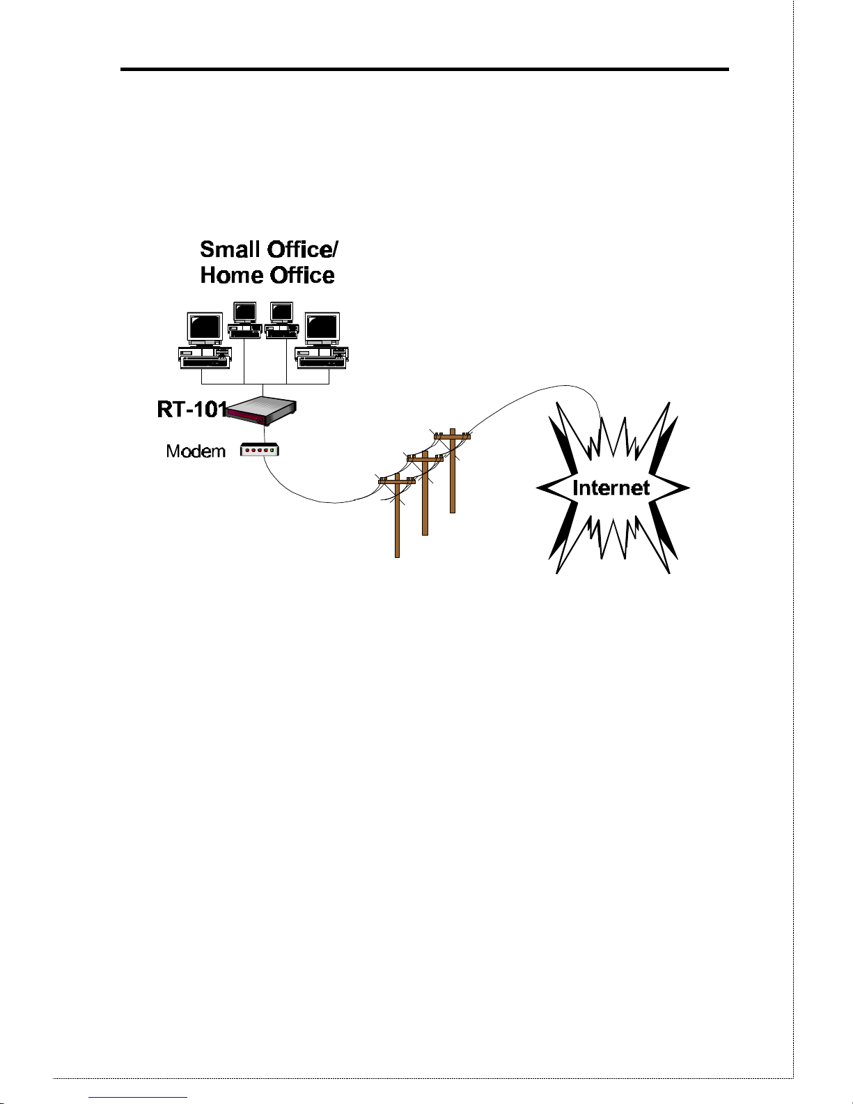
How the RT-101 Works
The RT-101 gives users across your network access to the
vast resources available on the Internet. Once the RT-101 is
installed and configured, the Internet is just a click away.
The RT-101 is assigned a unique IP addresses that allows it
to communicate directly with the Internet. Activating your
browser and inputting a URL (Universal Resource Locator)
produces a Internet bound data package that is routed
through the RT-101 to Internet. Additionally, since dial up
line fees are dependent on line usage, the RT-101 supports
the following cost saving functions:
IP Spoofing
IP protocol tends to be quite talkative; that is, it is always
requesting and sending RIPs (routing information packets)
to detect any change in resource status-- servers, routers
and other peripheral devices. Spoofing is a means of
filtering the chatter (RIPs) so that when no important data
is present the line can be dropped as defined by the
Disconnect time-out setting. After the line is dropped,
the spoofing mechanism fools the local network into
thinking the line is still up and that the Internet
resources are still available. Without spoofing, the line
would remain up indefinitely and huge line fees would be
incurred.
Dial On Demand
Dial On Demand is an intelligent feature that monitors the
Page 7
7
dropped communication link for transmission activity. If
activity is detected, a connection with the Internet will
automatically be re-established. To the user, it is as if the
line were never dropped.
Figure 1-1: Office to Internet Diagram
Page 8
RT-101 User’s Manual
8
Package Contents
Please inspect your package. The following items
should be included:
• The RT-101 Unit
• Power Adapter
• Configuration Serial Cable
• This User’s Manual
If any of the above items are damaged or missing, please
contact your RT-101 dealer as soon as possible.
Features Overview
This section describes the RT-101 features and their
functions. Please take a few minutes to familiarize
yourself with your new Internet router.
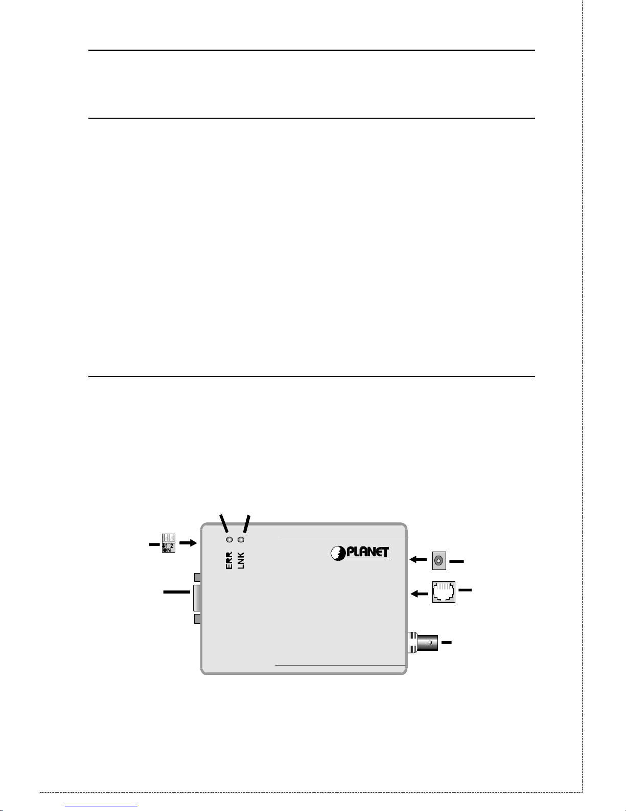
RT-101 Outlook
1
6
2
7
4
5
3
Smart IP Router
Figure 1-2: RT-101 Internet Router
Page 9

9
Feature Description
ΠPower port Connect the power adapter to this
port.
• 10Base-T port Connect 10Base-T cabling to this
port.
Ž 10Base2 port Connect 10Base2 cabling to this
port.
• Serial Port
Connect the modem to this
port.
•
DIP switches
Used to put the RT-101 in the
configuration mode. For
more information, refer to DIP
Switches table below.
‘ Error LED
This LED is used to indicate an
error. However, during
power On it is normal for this
LED to light. For more
information, see the following
LED Status Table.
’ Link LED
This LED should be on during
normal operation. For more
information, see the following
LED Status Table.
Page 10

RT-101 User’s Manual
10
Dip Switches
DIP Switches
SW1 SW2 Description
OFF OFF
ON OFF Normal Operation
OFF ON
ON ON Configuration Mode
LEDs
LED Status Table
LINK
Green LED
ERROR
Red LED
Description
On On During power On, both LEDs
should light then the Red
LED should go off. If
both LEDs stay on, there is a
hardware problem.
Consult your dealer.
On Off Normal Operation (Power On
Self Test OK)
Flashing Off Normal Operation (Receiving
Packets from LAN)
Flashing Flashing When both LEDs are flashing
intermittently, there is an
error. Contact your dealer
for technical support.
Pre-Installation Checklist
Before installing the Communication Server, you should:
• Remove the Sensitive Information page at the front of
this manual and store it in safe place. It contains
sensitive information on the Communication Server
security features.
Page 11

11
• Carefully read the entire manual.
• Ensure that you meet all hardware and software
requirements.
Requirements
• Any DEC VT52/VT100 compatible terminal
application including Telix, Crosstalk, ProComm,
SmartCom and Windows 95 Hyper Terminal.
• TCP/IP protocol enabled.
• Ethernet Network employing 10Base-T or 10Base2
cable.
• An external asynchronous modem.
• One standard serial cable to connect the modem and
RT-101.
• Router account with local ISP.
Page 12

Page 13

2 CONFIGURATION
Using the configuration software included with the RT-101,
you set the parameters necessary for Office to Internet
operation such as local and remote IP addresses, Net Masks
and telephone numbers. Prior to starting the configuration
process, ensure that you have a DEC VT52/VT100
compatible communication program.
1. With the RT-101 powered Off, connect the RT-101
serial port directly to your PC serial port
using the packaged configuration serial cable.
2. Set both of the RT-101’s DIP switches to their On
positions. See the Dip Switches table in Chapter 1
for more information.
3. Configure your DEC VT100 or DEC VT102
compatible communications program. If needed
consult the communication programs manual and
ensure that the following parameters are set:
• VT100
• 19200bps
• 8-bit data
• no parity
• 1 stop bit
• Software (XON/XOFF) flow control
4. Power On the RT-101 by plugging in the power
adapter. The configuration program will
automatically initiate.
5. Configure the RT-101 as described below.
Page 14

RT-101 User’s Manual
14
6. Once the configuration is complete, Save and reset
the device.
7. Power off the RT-101 and Set the DIP switches to
their OFF positions. Now you are ready to install the
RT-101 in the LAN for Internet Access.
Device Configuration
Once the RT-101 is powered On, it will automatically
initiate the configuration program. The table below
describes the keystroke commands used to navigate the
configuration program.
Keystroke Description
ESC Used to escape the input fields or
return to the previous menu.
Pressing ESC while at the first panel
will refresh the first panel.
TAB or è or
ê
Moves to the cursor to the next
option in descending order. If the
selected option is the last option,
pressing anyone of these keys will
return you to the first option.
ç or é Moves the cursor to the next option
in ascending order. If the selected
option is the first option, pressing
either of these keys will return you
to the last option.
ENTER Used to select the current option for
configuration.
Basic Configuration Menu
Page 15

15
Once the RT-101 is powered On, it will automatically
initiate the configuration program. Simply navigate to the
desired option as described in the previous table and press
enter. The configuration program will either move the
cursor to the input field, where you input configuration
settings directly from the keyboard, or display a predefined
list of values for you to choose from. Note that those
options contained in brackets [ ] have submenus.
[ Basic configuration ]
Local IP address: 203.70.212.5
Local network mask: 255.255.255.0
Remote IP address: 0.0.0.0
Remote network mask: 255.255.255.0
>IP broadcast address: 203.70.212.255
Default gateway IP address: 139.175.50.252
Local ID:
Local password:
Line type: Leased line (Null modem)
Baud rate: 38400 bps
Phone number: 3571058
Disconnect link if inactive for more than 0 minutes.
[Modem settings]
[Networking settings]
Save and reset device
Version 1.00
--------------------------------------------------------------------------------------------------------- ESC - Back to Main Menu, TAB - Change field, ENTER - Select
Page 16

RT-101 User’s Manual
16
Option Description
Local IP
Address
Enter the IP address of the RT-101
Local Network
Mask
Enter the Net Mask
Remote IP
Address
Enter the ISP provided IP address
Remote Network
Mask
Enter the ISP provided Net Mask
IP Broadcast
Address
Enter the broadcast address for your subnetwork segment
Default Gateway
IP Address
The correct IP addresses for this option
varies depending on implementation. If you
will using the RT-101 to connect directly
with the ISP, then enter the Remote IP
Address
Local ID
Enter the account name provided by your
ISP. This name will be used to negotiate a
connection with the ISP router using
PPP (Point to Point Protocol) when the ISP
router sends an user name authentication
request
Local Password
Enter ISP provided password. This
password will be used to negotiate a
connection with the ISP’s router using PPP
(Point to Point Protocol) when the remote
router sends a password authentication
request.
Page 17

17
Option Description
Line Type Select Lease Line(Null modem) if you are
using a lease line. When this option is
enabled, the Initial String, Answer On
String, Answer Off String, Hang-Up String
and Dial Prefix String are disabled and
RTS/CTS flow control is set. Otherwise
select Dial up line.
Baud rate
This option determines the data transmission
speed on the serial line. Ensure that the
selected speed is supported by your modem.
Below is a list of the available speeds
Phone No
Enter the ISP provided telephone number
following the conventions described in your
modem user’s manual.
Dial Up Line
>Leased Line (Null Modem)
4800 bps
9600 bps
19200 bps
>38400 bps
57600 bps
115.2k bps
230.4k bps
Page 18

RT-101 User’s Manual
18
Option Description
Disconnect Link
if inactive for
more than N
mutes:
This option sets the time that a connection
must remain inactive before the connection
is terminated. Acceptable “N” values
are 0-255 minutes with 0 having the special
meaning of no time-out. If using a lease line
set this value to zero.
[Modem Settings]
Selecting the Modem Settings option will cause the
following menu to appear.
Option Description
[ Modem Settings ]
Modem AT commands:
>Initial string: AT&F&C1&D3&K3S7=60
Answer on string: ATS0=1
Answer off string: ATS0=0
Hang-Up string: ~~~+++~~~ATH0
Dial prefix string: ATDT
Page 19

19
Initial String You must specify the following in your
Initial String:
• Fixed baud rate setting (disable
serial data rate adjustment)
• RTS/CTS flow control
• DCD to track the presence of a
carrier
• DTR off to hang-up modem
• DSR always on while modem is
on (Recommended)
Note:
For a modem whose AT
command set is the same as
represented in Appendix D, the
Initial String would look like the
following:
AT&F&B1&H3&C1&D2&S0
Consult your modem AT
command set for more
information on the Initial String
parameters described above.
Answer On
String
This option is reserved for future
implementations.
Answer Off
String
The Answer Off string tells the modem not
to answer
Hang-Up String
Tells the modem to break the connection
when PPP negotiation fails or when an
invalid user name or password is entered
Dial Prefix
String
Determines the dial tones and dial options to
be used. For more information, refer to the
ATD command in Appendix D.
Page 20

RT-101 User’s Manual
20
[Network Settings]
Selecting the Network Setting option will cause the
following menu to appear.
[ Network configuration ]
Serial Port:
>UDP checksum: Yes
Periodic RIP: Yes
Generate zero fill (BSD 4.2) broadcast address: No
Use ethernet IP address and network mask: No
IP address: 139.175.50.93
Network mask: 255.255.255.0
Local MTU: 1500
Remotw MTU: 1500
PPP Link:
Connect-tries: 3 Tries
Delay between two tries: 1 Minutes
Page 21

21
Option Description
Serial Port:
>UDP checksum: Yes
Periodic RIP: Yes
Generate zero fill (BSD 4.2) broadcast address: No
Use ethernet IP address and network mask: No
IP address: 139.175.50.93
Network mask: 255.255.255.0
Local MTU: 1500
Remotw MTU: 1500
PPP Link:
Connect-tries: 3 Tries
Delay between two tries: 1 Minutes
Page 22

RT-101 User’s Manual
22
Serial Port
The following options allow you to set the
parameters that define how the serial
interface is configured for data transmission.
UPD Checksum:
Set this option to Yes to enable
UDP Checksum. UDP Checksum
provides a check on all transmission
data to ensure data reliability. When
the UDP Checksum function is set
to No, the device ignores UDP
checksum on incoming packets and
uses zero checksum on out going
packets.
Periodic RIP:
Select this option to allow the RT101 to pass periodic RIP (routing
information) packets across the
WAN interface. The default setting
is Yes; however, when unnecessary
this increases the traffic on the
WAN link. Before changing this
setting ensure that the ISP
router does not RIP updates.
Generate Zero Fill (BSD 4.2)
Broadcast Address:
This option is provided for
compatibility with those networks
which have early implementations
based on UNIX BSD4.2. Setting this
option to Yes will cause all outgoing
broadcast IP addresses to be
translated into Zero Fill type
addresses.
Use Ethernet IP Address and
Network Mask:
Set this option to Yes to use the
Page 23

23
Local MTU
Local Maximum Transmission Unit defines
the largest IP packet to be transmitted to the
network by the device. The MTU affects
transmission efficiency and may need to be
adjusted. Valid values range from 8 to 1500
with 1500 being the default value
Remote MTU
Remote Maximum Transmission Unit
defines the largest IP packet to be
transmitted to the network by the device.
The MTU affects transmission efficiency
and may need to be adjusted. Valid values
range from 8 to 1500 with 576 being the
default value
PPP Link
The following parameters define how often
the RT-101 will attempt to establish a
connection with the ISP when the first
attempt fails.
Connect Tries:
Defines how many times the RT101 will try to establish a connection
with the ISP router. Valid entries
are 0-255 with 0 having the special
meaning of try until successful.
Delay Between Two Tries:
Specifies how much time to wait
between tries to establish a
connection with the ISP
router. Valid entries are 0-1440
minutes(24 hours) with 0 having the
special meaning of try again
immediately
Page 24

RT-101 User’s Manual
24
Save and Reset Device:
Select this option to save the new configuration
settings to the device.
The RT-101 is now configured. Proceed to Chapter 3 for
LAN Installation.
Page 25

3 LAN INSTALLATION
Installing your new RT-101 in your existing Ethernet LAN
is quick and easy. To install your RT-101, follow the
instructions below:
1. Choose an Installation Site
Select a place on the network to install the
Communication Server unit. Remember that you
need phone jacks and power outlets near your chosen
location.
2. Connect Network Cable
The RT-101 supports two types of network cables:
Thin Ethernet (10Base-2, BNC connector) and
Twisted Pair Ethernet (10Base-T, RJ-45 connector).
During power up, the unit automatically detects the
type of network cable and adjusts to that
environment.
10Base-2 Cabling:
If your network uses 10Base-2 cable, insert a BNC Tconnector into the RT-101’s BNC port. Connect
the cable to one end of the T-connector and connect
the outgoing cable to the other end. If the RT-101
is at the end of the network, then cap off the other
end of T- connector with a 50-ohm terminator. Also,
keep in mind that the maximum effective length
between the ends of a 10Base-2 network is 185
meters.
10Base-T Cabling:
If your network uses 10Base-T cable, insert one end
of a 10Base-T cable into the RT-101’s RJ-45 phone
jack and the other end into the 10Base-T hub. Keep in
mind that the maximum effective length from the hub
to the device is 100 meters.
Page 26

RT-101 User’s Manual
26
Warning: Do not attempt to connect more than one
type of cable at the same time or change the
network cable while the RT-101 is powered
On.
3. Connect Modem & Phone Line
Connect the modem, using a standard serial cable, to
the RT-101’s serial port. Next, connect a
telephone line from an RJ-11 style phone jack to the
modem.
4. Connect Power Adapter
Connect the modem power adapter to the
modem and the RT-101’s power adapter to the RT-
101. Power both devices On.
Warning: Only use the power adapter provided with the
RT-101. Using a different one may cause
hardware damage.
5. Check the LEDs
When the RT-101 is powered On, both LEDs should
light, then the Error LED should go off. If the Error
LED stays on, there is a hardware problem.
Consult your dealer. For more information on the
LEDs, refer to the LED Status Table in Chapter 1.
Page 27

4 OPERATION
Once the RT-101 has been configured and installed in your
network, it is ready for use. To access the Internet, follow
the steps below:
1. Consult the ISP data sheet and configure the
following IP parameters on your workstation:
• IP Address
• Default Gateway
• DNS (Domain Name Server)
2. Activate your Browser.
3. Enter the appropriate destination URL or IP address.
Page 28

Page 29

A TROUBLESHOOTING
This chapter covers some common problems that may be
encountered while using the RT-101 and some possible
solutions to them. If you follow the suggested steps and
the RT-101 still does not function properly, contact your
dealer for further advice.
Problem 1:
I configured and installed the RT-101
in the network, but I can get it
to respond.
Solution 1:
If the configuration settings are
correct, then you probably forgot to
set the dip switches back to their Off
positions after configuration. Power
Off the RT-101 and ensure that the
dip switches are in their Off
positions.
Problem 2:
Data Transmissions are very slow.
Solution 2:
Check and ensure that the Initial
String is configured to RTS/CTS
flow control.
Problem 3:
When I enter a URL or IP address I
get a time out error.
Solution 3:
Any number of things could be
causing this. Try the following
troubleshooting steps.
1. If this is first time you have used
Page 30

RT-101 User’s Manual
30
your browser, ensure that your
workstations IP settings,
including IP address, Default
Gateway, and DNS are correct.
2. Ping the RT-101. Go to the DOS
prompt and enter the following
command:
Ping xxx.xxx.xxx.xxx
where xxx.xxx.xxx.xxx is the
RT-101 IP address.
3. If the ping command fails,
consult your network
administrator. The RT-101 may
be powered Off.
4. If the ping command is
successful, the to ping the
remote router.
5. If the remoter router ping
command fails, it may mean one
of the following:
• The ISP is overloaded
• You have entered the wrong
IP address
• The ISP system is
down.
Consult your system administrator
for help.
6. If the remoter router ping is
successful, then try to ping the
DNS. If successful, then you
should be able to access the
Internet.
Problem 4
How do I configure the RT-101 to
work with the ISP (Internet Service
Provider)?
Page 31

31
Solution 4:
The ISP must provide the customer
with basic information concerning
security and parameter settings. The
data sheet below is from an ISP to a
customer who has a router account
and is using a dial-up line.
Basic Information:
User Name: Stymme
Password: Keepquite
Phone Number: 4567890
Setting Parameters:
IP address range: 202.73.93.0-255
Router LAN IP address: 202.73.93.190
Remote Gateway IP address: 167.94.214.254
Remote Name: Charlie
DNS IP address: 167.94.197.1
Local Netmask: 255.255.255.0
Local DNS IP address: 202.73.93.161
Remote Netmask: 255.255.248.0
Note: The information received from the ISP will vary
according to the type service you buy and the type
of routers used by the ISP. ISPs that use traditional
routers will include an additional parameter, Router
WAN IP address.
Given the data sheet above, the RT101 main configuration
screen would look like the
following:
Page 32

RT-101 User’s Manual
32
Notice that the Remote IP address
and the Default Gateway IP
address are the same.
Page 33

B AT COMMAND SET
Basic AT Command Set
Command Description
<any key>
Terminate current connection attempt
+++
Escape sequence code, entered in data state,
wait for modem to return to command state
ATA
Force answer mode on-line
ATBn
Handshake operation
B0 Select ITU-T V.22 for 1200 bps
communication
B1 Select Bell 212A for 1200 bps
communication
ATD
Dial number and options that follow
P Pulse dial
T Tone dial
, Pause for a specified time
; Return to command state after dialing
! Hook flash, call transfer
W Wait for second dial tone
@ Wait for 5-second silence before proceeding,
otherwise return O ANSWER”
R Reverse Dial (Originate a call in answer
mode)
Page 34

RT-101 User’s Manual
34
Command Description
ATDL
Dial last number
ATDSn
Dial number stored in NVRAM at position
n. n=0-9
ATEn
Command mode local echo of keyboard
commands
E0 Echo off
E1 Echo on
ATHn
On/Off hook control
H0 Hang up (on hook), same as ATH
H1 Get off hook
ATIn
Display inquired information
I0 Display product code
I1 Display product information and ROM
checksum
I2 Link status report
ATLn
Speaker volume control. n=0-7
ATMn
Speaker control
M0 Speaker always off
M1 Speaker on until carrier is detected
M2 Speaker always on
M3 Speaker on after last digit dialed, off at
carrier detect
ATNn
Ring volume control, n=0 disables ring
function. n=0-7
ATO
Return to on-line state
ATP
Pulse dial
Page 35

AT Command Set
35
Command Description
ATQn
Result code displayed
Q0 Modem returns result code
Q1 Modem does not return result code
Q2 Return result code but quiet in answer mode
(will not show in AT&Vn)
ATS0=n
Number of rings required before modem
answers. n=0 disables auto-answer.
ATSr.b=n
Set bit b of S-register r to n. (0 or 1)
ATSr.b?
Inquiry bit b of S-register r
ATSr=n
Set S-register r to value n, where n is a
decimal number between 0-255
ATSr?
Display value stored in S-register r
ATT
Tone dial
ATVn
Verbal/Numeric result codes
V0 Display result codes in numeric form
V1 Display result codes in verbose form
ATXn
Result code options. n=0-7
ATZn
Reset the modem and set power-on profile.
n=0-4
Zn Reset modem and load user profile n (0-3)
Z4 Reset modem and load factory settings
AT$
Help, Basic command summary
AT&$
Help, Extended AT& command summary
AT*$
Help, Extended AT* command summary
Page 36

RT-101 User’s Manual
36
Extended ”AT&” Command Set
(Includes RTS/CTS Flow Control Commands)
Command Description
&Bn
Data rate, terminal-to-modem
&B1 DTE/DCE rate fixed at DTE setting
&Cn
Carrier Detect operations
&C1 Carrier Detect tracks presence of carrier
&Dn
Data Terminal Ready (DTR) operations
&D2 DTR off causes modem to hang up
&F
Load the default factory settings,
&Hn
Data flow control, DTE/DCE
&H0 Flow control disabled
&H3 Hardware (RTS/CTS) flow control
&H4 Software (XON/XOFF) flow control
&Sn
Data Set Ready (DSR)
&S0 DSR overridden, DSR always on
Page 37

Specification
37
C SPECIFICATIONS
Model No.:
RT-101
CPU
80186, 25MHz
Dial-Out
Protocol:
TCP/IP
Frame Type:
IEEE 802.2/802.3, Ethernet II,
SNAP
Network
Interface:
Ethernet 10Base-2(BNC) and
10Base-T (UTP)
Serial Port:
One male DB-9 connector
Max. Asyn.
Speed
230.4 Kbps
UART
16550
LEDS
2
External Power
Adapter
9VDC
Dimension(mm)
120 x 86 x 30 (LxWxH)
Page 38

RT-101 User’s Manual
38
Null Modem Pin Assignments
Figure C-1: Null Modem Pin Out
 Loading...