

Page 1

Powerline Wireless Router
PRT-301W
User’s Manual
Page 2

Copyright
Copyright 2005 by PLANET Technology Corp. All rights reserved. No part of this publication may be reproduced, transmitted, transcribed, stored in a retrieval system, or translated
into any language or computer language, in any form or by any means, electronic, mechanical, magnetic, optical, chemical, manual or otherwise, without the prior written permission of
PLANET.
PLANET makes no representations or warranties, either expressed or implied, with respect
to the contents hereof and specifically disclaims any warranties, merchantability or fitness for
any particular purpose. Any software described in this manual is sold or licensed "as is".
Should the programs prove defective following their purchase, the buyer (and not this company, its distributor, or its dealer) assumes the entire cost of all necessary servicing, repair,
and any incidental or consequential damages resulting from any defect in the software. Further, this company reserves the right to revise this publication and to make changes from
time to time in the contents hereof without obligation to notify any person of such revision or
changes..
All brand and product names mentioned in this manual are trademarks and/or registered
trademarks of their respective holders.
Federal Communication Commission Interference Statement
This equipment has been tested and found to comply with the limits for a Class B digital device, pursuant to Part 15 of FCC Rules. These limits are designed to provide reasonable
protection against harmful interference in a residential installation. This equipment generates, uses, and can radiate radio frequency energy and, if not installed and used in
accordance with the instructions, may cause harmful interference to radio communications.
However, there is no guarantee that interference will not occur in a particular installation. If
this equipment does cause harmful interference to radio or television reception, which can be
determined by turning the equipment off and on, the user is encouraged to try to correct the
interference by one or more of the following measures:
1. Reorient or relocate the receiving antenna.
2. Increase the separation between the equipment and receiver.
3. Connect the equipment into an outlet on a circuit different from that to which the receiver
is connected.
4. Consult the dealer or an experienced radio technician for help.
FCC Caution:
To assure continued compliance.(example-use only shielded interface cables when connecting to computer or peripheral devices). Any changes or modifications not expressly approved
by the party responsible for compliance could void the user’s authority to operate the equipment.
This device complies with Part 15 of the FCC Rules. Operation is subject to the Following
two conditions: (1) This device may not cause harmful interference, and (2 ) this Device must
accept any interference received, including interference that may cause undesired operation.
Federal Communication Commission (FCC) Radiation Exposure
Statement
This equipment complies with FCC radiation exposure set forth for an uncontrolled environment. In order to avoid the possibility of exceeding the FCC radio frequency exposure limits,
human proximity to the antenna shall not be less than 20 cm(8 inches) during normal operation.
R&TTE Compliance Statement
ii
Page 3

This equipment complies with all the requirements of DIRECTIVE 1999/5/CE OF THE
EUROPEAN PARLIAMENT AND THE COUNCIL OF 9 March 1999 on radio equipment and
telecommunication terminal Equipment and the mutual recognition of their conformity
(R&TTE)
The R&TTE Directive repeals and replaces in the directive 98/13/EEC (Telecommunications
Terminal Equipment and Satellite Earth Station Equipment) As of April 8,2000.
Safety
This equipment is designed with the utmost care for the safety of those who install and use it.
However, special attention must be paid to the dangers of electric shock and static electricity
when working with electrical equipment. All guidelines of this and of the computer manufacture must therefore be allowed at all times to ensure the safe use of the equipment.
Revision
User’s Manual for PLANET Powerline Wireless Router
Model: PRT-301W
Rev: 1.0 (March, 2005)
Part No. EM-PRT301W
iii
Page 4

TABLE OF CONTENTS
CHAPTER 1 INTRODUCTION......................................................................................1
1.1 Package Contents...........................................................................................1
1.2 System Requirements....................................................................................1
1.3 Features...........................................................................................................1
1.4 Specification....................................................................................................2
1.5 Wireless Performance....................................................................................2
CHAPTER 2 HARDWARE INSTALLATION..................................................................5
2.1 Hardware Connection.....................................................................................5
2.2 LED Indicators.................................................................................................5
CHAPTER 3 INITIAL SETUP........................................................................................7
3.1 Overview..........................................................................................................7
3.2 Setup Wizard...................................................................................................7
CHAPTER 4 ADVANCED SETUP...............................................................................10
4.1 System...........................................................................................................10
4.1.1 System Time..........................................................................................10
4.1.2 Administrator Settings............................................................................10
4.1.3 Firmware Upgrade.................................................................................11
4.1.4 Configuration Tools................................................................................11
4.1.5 MAC Clone.............................................................................................12
4.1.6 Status.....................................................................................................12
4.1.7 System Log............................................................................................13
4.1.8 Reboot...................................................................................................13
4.2 WAN................................................................................................................13
4.2.1 Dynamic IP.............................................................................................13
4.2.2 Static IP..................................................................................................14
4.2.3 PPPoE....................................................................................................14
4.2.4 PPTP......................................................................................................15
4.2.5 DNS.......................................................................................................15
4.3 LAN.................................................................................................................16
4.3.1 LAN Settings..........................................................................................16
4.3.2 DHCP Client List....................................................................................17
4.4 Wireless.........................................................................................................17
4.4.1 Wireless Settings...................................................................................17
4.4.2 Security Settings....................................................................................18
4.5 NAT.................................................................................................................18
4.5.1 Special Application.................................................................................18
4.5.2 Virtual Server.........................................................................................19
4.6 Firewall...........................................................................................................20
4.6.1 Block WAN Ping....................................................................................20
4.6.2 Client Filtering........................................................................................20
4.6.3 MAC Control..........................................................................................21
4.6.4 DMZ.......................................................................................................21
4.7 Routing...........................................................................................................21
4.7.1 Static Routing.........................................................................................21
4.7.2 Dynamic Routing....................................................................................22
4.7.3 Routing Table List..................................................................................22
CHAPTER 5 POWERLINE NETWORK UTILITY........................................................23
5.1 Install the Powerline Network Utility...........................................................23
5.2 Use the Powerline Network Utility...............................................................23
APPENDIX A TROUBLESHOOTING..........................................................................26
i
Page 5

Chapter 1
Introduction
As the speedy network expansion, the transmitting medium is no longer restricted to physical
network cables. The technologies of wireless and powerline are growing more rapidly than
traditional wired networking. The PRT-301W is multiple standards compliant with IEEE
802.3/802.3u for Ethernet, IEEE 802.11b/g for wireless LAN, and HomePlug Powerline Alliance
v1.0 for powerline network. It can easily accommodate to existing network, regardless of type.
Furthermore, the PRT-301W can combine three different types of networks into one and enjoy
the high speed of Ethernet, freedom of wireless and simplicity of powerline.
1.1 Package Contents
Make sure that you have the following items:
n PRT-301W
n Dipole Antenna
n RJ-45 cable
n Quick Installation Guide
n User’s manual
n Power Adapter
Note:
If any of the above items are missing, contact your supplier as soon as
possible.
1.2 System Requirements
Before installation, please check the following requirements with your equipment.
n One RJ-45 Broadband Internet connection
n One PC with an installed 10Mbps, 100Mbps, or 10/100 Mbps Ethernet card
n TCP/IP network protocol for each PC
n UTP network cable with RJ-45 connector
n Microsoft Internet Explorer 4.0 or later, or Netscape Navigator 4.0 or later.
(5.0 and 4.7, respectively, are strongly recommended.)
1.3 Features
n Internet connection sharing for every node with one external IP
n Support Homeplug Powerline Alliance v1.0
n Support 802.11g wireless LAN, and 802.3/802.3u 10M/100M Ethernet
n Three 10/100Mbps Auto-negotiation and Auto-MDIX switching ports for flexibility network
connectivity
n 64-bit, 128-bit WEP (Wired Equivalent Privacy)
n Web Configuration provide a user friendly interface for the user to configure through web
browser
n Support DHCP server and client
n Support MAC Filter
1
Page 6

1.4 Specification
Hardware
Port Four 10/100Base-TX ports (WAN * 1, LAN * 3)
One powerline port
LED Indicators System: 1 LEDs; PWR
Powerline: 2 LEDs; LNK, ACT
Wireless: 1 LED; WLAN
LAN: 3 LEDs; LNK/ACT
WAN: 1 LED; WAN
Antenna One Dipole Antenna
Wireless LAN
Standard IEEE 802.11g
Signal Type DSSS (Direct Sequence Spread Spectrum)
Modulation QPSK / BPSK / CCK/OFDM
Output Power 15dBm
Data Encryption 64 bit / 128 bit WEP encryption
Frequency 2.4GHz - 2.484GHz
Channel 11 Channels (FCC / US, Canada)
13 Channels (ETSI / Europe)
14 Channels (TELEC / Japan)
Data Rate 802.11b: 1 / 2 / 5.5 / 11 Mbps
802.11g: 6 / 9 / 12 / 18 / 24 / 36 / 48 / 54 Mbps
Internet Connectivity
Internet Connection Fixed IP, PPPoE, PPTP, Dynamic IP
Protocol TCP/IP, NAT, DHCP, HTTP, RIPv1/v2
Advanced Function Virtual Server, DMZ
Powerline
Standard HomePlug Powerline Alliance v1.0
Data Rate Up to 14Mbps over powerline
1.5 Wireless Performance
The following information will help you utilizing the wireless performance, and operating coverage of PRT-301W.
1. Site selection
To avoid interferences, please locate PRT-301W and wireless clients away from transformers, microwave ovens, heavy-duty motors, refrigerators, fluorescent lights, and other
industrial equipments. Keep the number of walls, or ceilings between AP and clients as
2
Page 7

few as possible; otherwise the signal strength may be seriously reduced. Place PRT301W in open space to improve the coverage.
2. Environmental factors
The wireless network is easily affected by many environmental factors. Every environment is unique with different obstacles, construction materials, weather, etc. It is hard to
determine the exact operating range of PRT-301W in a specific location without testing.
3. Antenna adjustment
The bundled antenna of PRT-301W is adjustable. Firstly install the antenna pointing
straight up, then smoothly adjust it if the radio signal strength is poor. But the signal reception is definitely weak in some certain areas, such as location right down the antenna.
Moreover, the original antenna of PRT-301W can be replaced with other external antennas to extend the coverage. Please check the specification of the antenna you want to
use, and make sure it can be used on PRT-301W.
4. WLAN type
If PRT-301W is installed in an 802.11b and 802.11g mixed WLAN, its performance will
reduced significantly. Because every 802.11g OFDM packet needs to be preceded by an
RTS-CTS or CTS packet exchange that can be recognized by legacy 802.11b devices.
This additional overhead lowers the speed. If there are no 802.11b devices connected, or
if connections to all 802.11b devices are denied so that PRT-301W can operate in 11gonly mode, then its data rate should actually 54Mbps.
3
Page 8

Page 9
the
PRT-301W
is successfully connected to a device through the corr
e-
Chapter 2
Hardware Installation
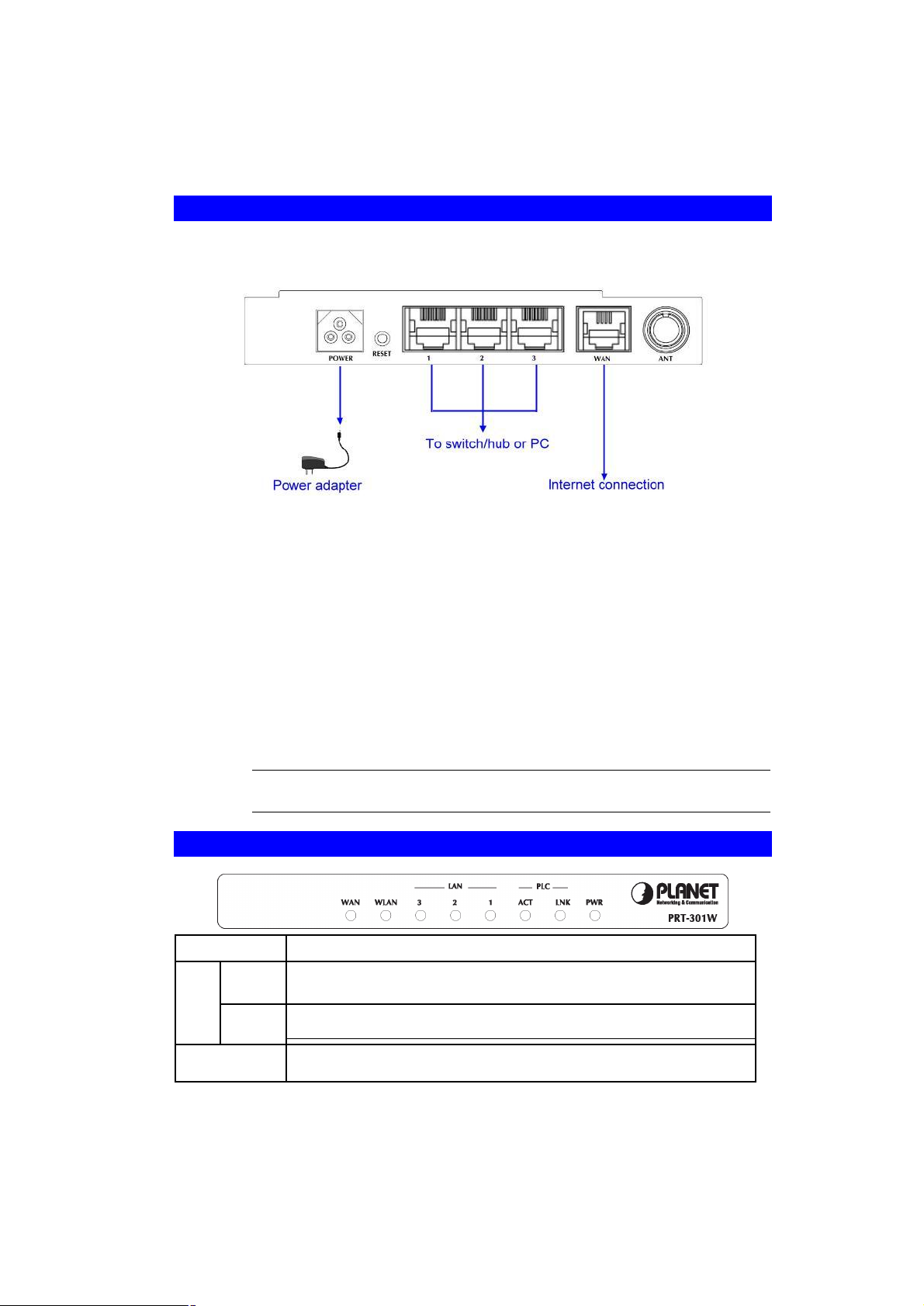
2.1 Hardware Connection
Before you proceed with the installation, it is necessary that you have enough information about
the PRT-301W.
1. Locate an optimum location for the PRT-301W. The best place for your PRT-301W
is usually at the center of your wireless network, with line of sight to all of your mobile
stations.
2. Assemble the antenna to PRT-301W. Try to place them to a position that can best
cover your wireless network. The antenna’s position will enhance the receiving sensitivity.
3. Connect RJ-45 cable to PRT-301W LAN port. Connect one of the LAN ports on PRT301W to your LAN switch/hub with a RJ-45 cable.
4. Connect RJ-45 cable to PRT-301W WAN port. Connect ADSL/Cable Modem to the
WAN port on PRT-301W. Use the cable supplied with your modem. If no cable was
supplied with your modem, please use a RJ-45 Ethernet cable.
5. Plug in power adapter and connect to power source. After power on, PRT-301W will
start to operate. In the mean time, PRT-301W is connected to the powerline network.
Note:
ONLY use the power adapter supplied with the PRT-301W. Otherwise,
the product may be damaged.
2.2 LED Indicators
PWR
LNK
PLC
ACT
Router with proper power connection.
The LNK LED illuminates when a successful connection is made between
the PRT-301W and another powerline device or network.
The ACT LED is flashing when the PRT-301W is actively sending or
receiving data over the powerline network.
LAN (1-3)
The LAN LEDs serve two purposes. If the LED continuously illuminated,
5
Page 10

sponding port (1, 2 or 3).
If the LED is flashing, the PRT-301W is actively sending or receiving data
over that port.
WLAN
WAN
The WLAN LED flashes when the wireless works.
The WAN illuminates when the PRT-301W is powered on and flashes
when the PRT-301W is actively sending or receiving data over the WAN
network.
6
Page 11
Chapter 3
Initial Setup
3.1 Overview
Web configuration provides a user-friendly graphical user interface (web pages) to manage
your PRT-301W. A PRT-301W with an assigned IP address allows you to monitor and configure via web browser easily.
1. Open your web browser.
2. Enter the IP address of your PRT-301W in the address field (the default IP address is
192.168.1.1).
3. The homepage of PRT-301W appears as below.
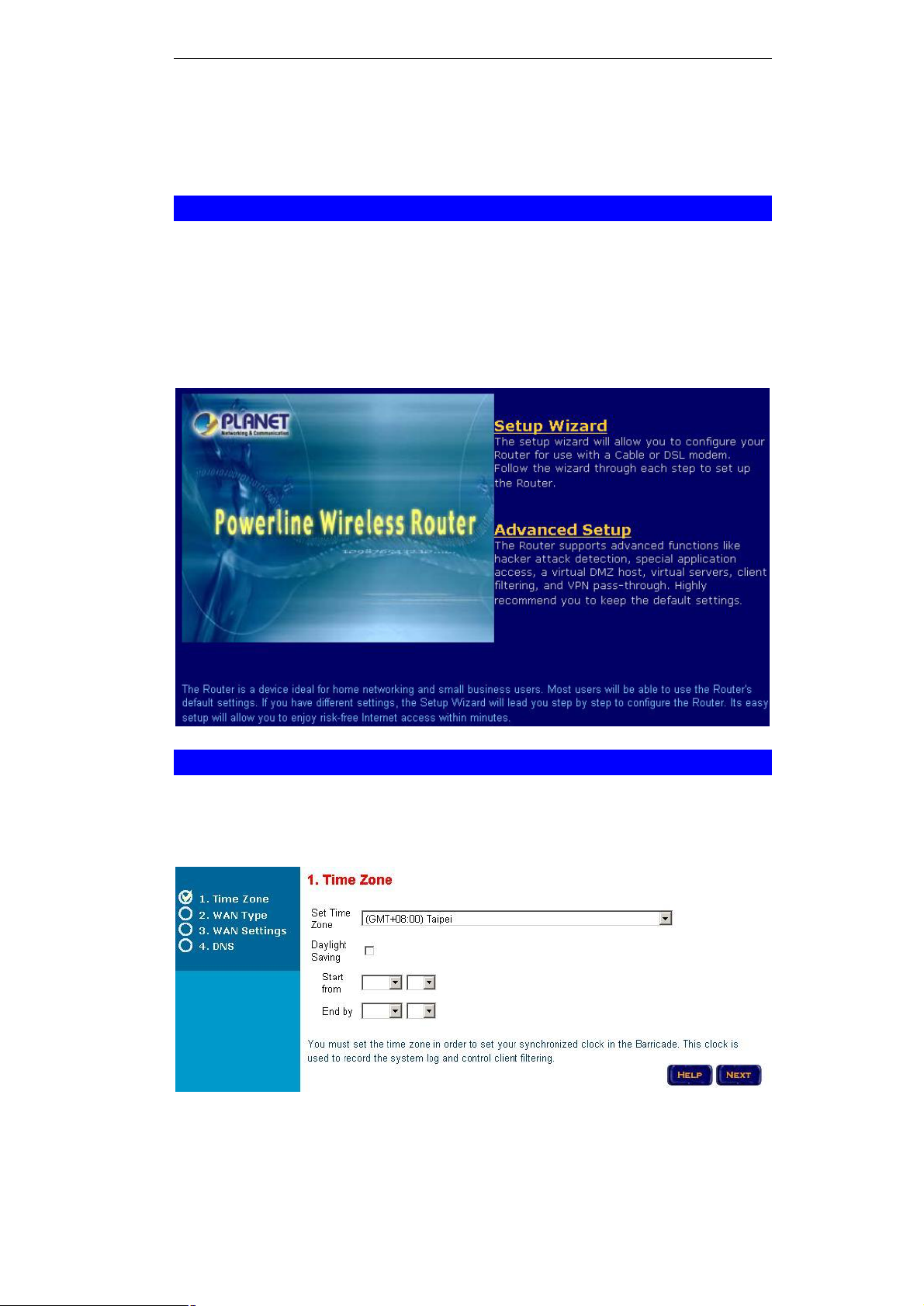
3.2 Setup Wizard
The Setup Wizard allows you to complete the initial configurations of PRT-301W with step-bystep instructions.
Step 1: Time Zone
7
Page 12

Select your time zone from the drop-down list. If necessary, enable the “Daylight Saving” option
and configure the start and end time below. Click “NEXT” to continue.
Step 2: WAN Type
Select your Internet connection type in this page.
Step 3: WAN Settings
The contents of this page are depending on which option you selected in previous page.
Please obtain all necessary information from your ISP and fill the respective fields with proper
settings. Click “NEXT” to continue.
Step 4: DNS
8
Page 13

Key in the IP address of your DNS server, if any. Click “FINISH” to complete the Setup Wizard.
9
Page 14

Chapter 4
Advanced Setup
4.1 System
The sub pages contained in System provide the basic configuration tools for the Router.
4.1.1 System Time
Set Time Zone
Daylight Saving
Start from
End by
Select your time zone from the drop-down list.
Enable this option if necessary.
If the above option is enabled, select the start and end time here.
4.1.2 Administrator Settings
You can change the administrator password and setup remote management options here.
10
Page 15
Password Settings
Current Password
Password
Re-type password
Idle Time Out
Remote Management
Enable
IP Address
Port
Enter the password value currently used here. There is no password by default. It is recommended to change the default setting for
better protection.
Enter the new password value in this field.
Enter the new password again for confirmation.
Specify the time that will elapse before the PRT-301W times out of
a connection.
Select to enable Remote Management option.
Type the IP address of the PC that can be used for remote man-
agement.
Specify the remote management port number.
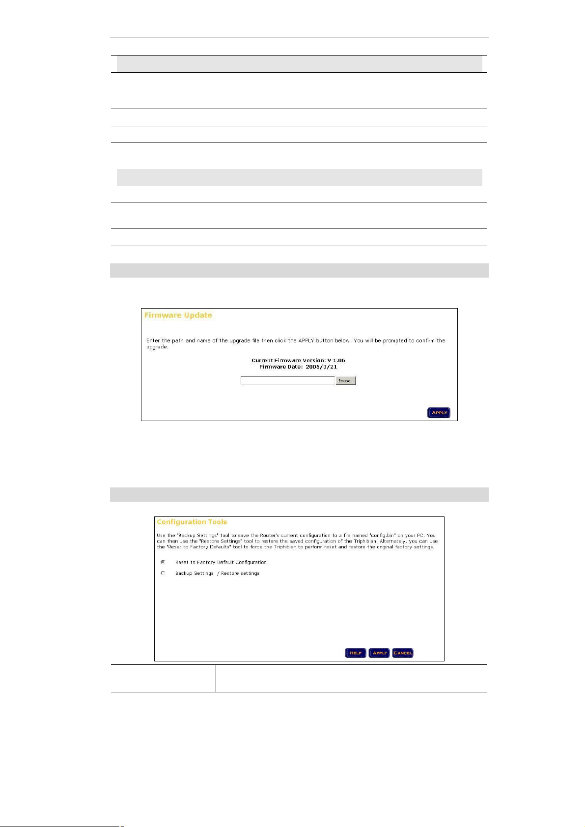
4.1.3 Firmware Upgrade
You can upgrade the PRT-301W with new firmware in this page.
1. Download the latest firmware from PLANET web site, and save it to your local disk.
2. Click “Browse…” and find out the location of the downloaded file.
3. Select the file and click “APPLY” to start the firmware upgrade.
4.1.4 Configuration Tools
Reset to Factory
Default Configuration
Use this option to restore your PRT-301W with factory default
settings.
11
Page 16

Backup Settings /
Restore Settings
4.1.5 MAC Clone
Host Name
MAC Address
It is an optional setting, but may be required by some Internet Service
Provider.
By default, this field is set to the MAC address of PRT-301W’s WAN port.
If required by your Service Provider, you can also use the "Clone MAC
Address" button to copy the MAC address of the Network Interface Card
installed in your PC and replace the WAN MAC address.
4.1.6 Status
Use the "Backup Settings" tool to save the current configuration to
a file named "config.bin" on your PC. You can then use the
"Restore Settings" tool to restore the saved configuration.
This page shows you the connection status for the PRT-301W's WAN/LAN interfaces, firmware
and hardware version numbers, and the number of connected clients to your network.
12
Page 17

4.1.7 System Log
This page displays all illegal attempts to access your network.
4.1.8 Reboot
Click “Reboot” to restart the PRT-301W in the event the system is not working properly.
4.2 WAN
The PRT-301W supports four types of Internet connections.
4.2.1 Dynamic IP
MTU (1400-1492)
Pre-request IP
BigPond
Type the MTU value in the field. It is suggested to set it to 1492.
You can leave this field blank if your ISP does not provide related
information.
If your ISP need you to do the BigPond login, please enable this option
and fill the username, password, and server name.
13
Page 18
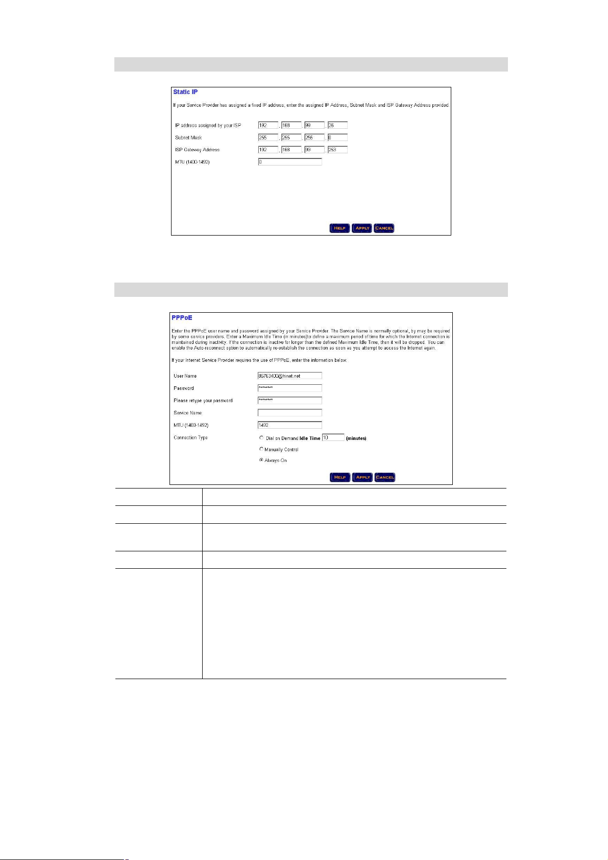
4.2.2 Static IP
If your ISP has assigned you a fixed IP address, enter the assigned IP address, subnet mask,
and Gateway address in respective field.
4.2.3 PPPoE
User Name
Password
Service Name
MTU (1400-1492)
Connection Type
Type your PPPoE username.
Type your PPPoE password.
This field is normally optional. However, it may require by some service
providers.
Type the MTU value in the field. It is suggested to set it to 1492.
There are three options available.
Dial on Demand: when enabled, the PRT-301W automatically con-
nects to the Internet when the LAN PC activates web browser. The “Idle
Time” field specifies the time that will elapse before PRT-301W times
out a connection.
Manually Control: manually controls the Internet connection by the
buttons on the “Status” page.
Always On: keeps an always-on Internet connection.
14
Page 19

4.2.4 PPTP
PPTP Account
PPTP Password
Host Name
Service IP Address
My IP Address
My Subnet Mask
Connection ID
MTU (1400-1460)
Maximum Idle Time
Auto-reconnect
4.2.5 DNS
Type your PPTP account.
Type your PPTP password.
Type the host name if your ISP provides you the related informa-
tion.
Type the service IP address your ISP provides.
Type the IP address your ISP assigns to you.
Type the subnet mask your ISP provides.
Type the connection ID if your ISP provides you the related informa-
tion.
Type the MTU value in this field. It is suggested to set it to 1460.
Specify the time that will elapse before PRT-301W times out a
connection.
With this option enabled, PRT-301W will try to rebuild the Internet
connection once the link is down.
15
Page 20

DNS Address
Secondary DNS
Address
4.3 LAN
4.3.1 LAN Settings
Type the DNS address if your ISP provides you the related information.
Type the secondary DNS address for redundant use.
IP Address
Subnet Mask
DHCP Server
Starting Address
Ending Address
Lease Time
Local Domain
Name
This is the LAN IP address of this router. The default value is
192.168.1.1.
It is fixed to 255.255.255.0
Enables this option to allow the router to automatically assign IP
address to the LAN clients.
Type the start IP address of the IP pool.
Type the end IP address of the IP pool.
Select the proper expired duration of the IP leased by PRT-301W.
Type the local domain name in this field. It is an optional field.
16
Page 21

4.3.2 DHCP Client List
This page displays the profiles of the DHCP clients
4.4 Wireless
4.4.1 Wireless Settings
Session ID
DS Channel
Wireless Mode
Transmitting Rate
SSID Broadcast
Type a SSID in this field. The SSID of any wireless client must match
the SSID typed here in order for the wireless client to access the LAN
and WAN via PRT-301W.
Select a work channel for wireless communications.
There are four options available. Select the proper mode according to
your practical application.
Select one of the wireless communication data rates. It is suggested
to set it to Auto.
Enable or Disable SSID Broadcast feature.
17
Page 22

4.4.2 Security Settings
Data Security
Encryption Key
64 bits WEP Key
1 ~4
128 bits WEP
Key
Select the encryption from the drop-down list.
If 64 bits WEP key is selected, please choose which key you prefer to
use in this field.
Enter the value of each key. The key value must be 10 hexadecimal
digits.
Enter the key value. The key value must be 26 hexadecimal digits.
4.5 NAT
4.5.1 Special Application
18
Page 23

2
3
Some applications require multiple connections, such as Internet gaming, video conferencing,
Internet telephony and others. These applications cannot work when Network Address Translation (NAT) is enabled. If you need to run applications that require multiple connections, specify
the port normally associated with an application in the "Trigger Port" field, select the protocol
type as TCP or UDP, then enter the public ports associated with the trigger port to open them
for inbound traffic.
For example:
ID Trigger Port
1
28800 UDP 2300-2400, 47624 UDP MSN Game Zone
28800 UDP 2300-2400, 47624 TCP MSN Game Zone
6112 UDP 6112 UDP Battle.net
Trigger
Type
4.5.2 Virtual Server
Public Port Public Type
Comment
If you configure the Router as a virtual server, remote users accessing services such as Web
or FTP at your local site via public IP addresses can be automatically redirected to local servers configured with private IP address. In other words, depending on the requested service
(port number), the Router redirects the external service request to the appropriate server.
For example:
ID Mapping Ports Server IP Enabled
1 200 192.168.2.20
2 333 192.168.2.12
3 455 192.168.2.28
19
Page 24

4.6 Firewall
4.6.1 Block WAN Ping
This page allows you to prevent the hackers from testing the services of the Router. "Discard
ping from WAN side", "Drop Port Scan Packets" and "Discard NetBios Packets" cause the
Router to not respond to the hacker scan packets from the public WAN IP address.
Some applications need to communication with the security port(113). When you enable the
"Drop Port Scan Packets", enable the "Allow to Scan Security Port" is recommended.
4.6.2 Client Filtering
You can filter Internet access for local clients based on IP addresses, application types, (i.e.,
HTTP port), and time of day.
For example, this screen shows that clients in the address range 192.168.1.50-99 are permanently restricted from using FTP (Port 21), while clients in the address range 192.168.1.110119 are blocked from browsing the Internet from Monday through Friday.
20
Page 25

4.6.3 MAC Control
You can block certain client PCs accessing the Internet based on MAC addresses.
4.6.4 DMZ
If you have a client PC that cannot run Internet application properly from behind the NAT
firewall or after configuring the Special Applications function, you can open the client up to
unrestricted two-way Internet access.
Enter the IP address of a DMZ host to this screen. Adding a client to the DMZ (Demilitarized
Zone) may expose your local network to a variety of security risks; so only use this option as a
last resort.
4.7 Routing
4.7.1 Static Routing
21
Page 26
The static routing function determines the path that data follows over your network before and
after it passes through your router. You can use static routing to allow different IP domain users
to access the Internet through this device.
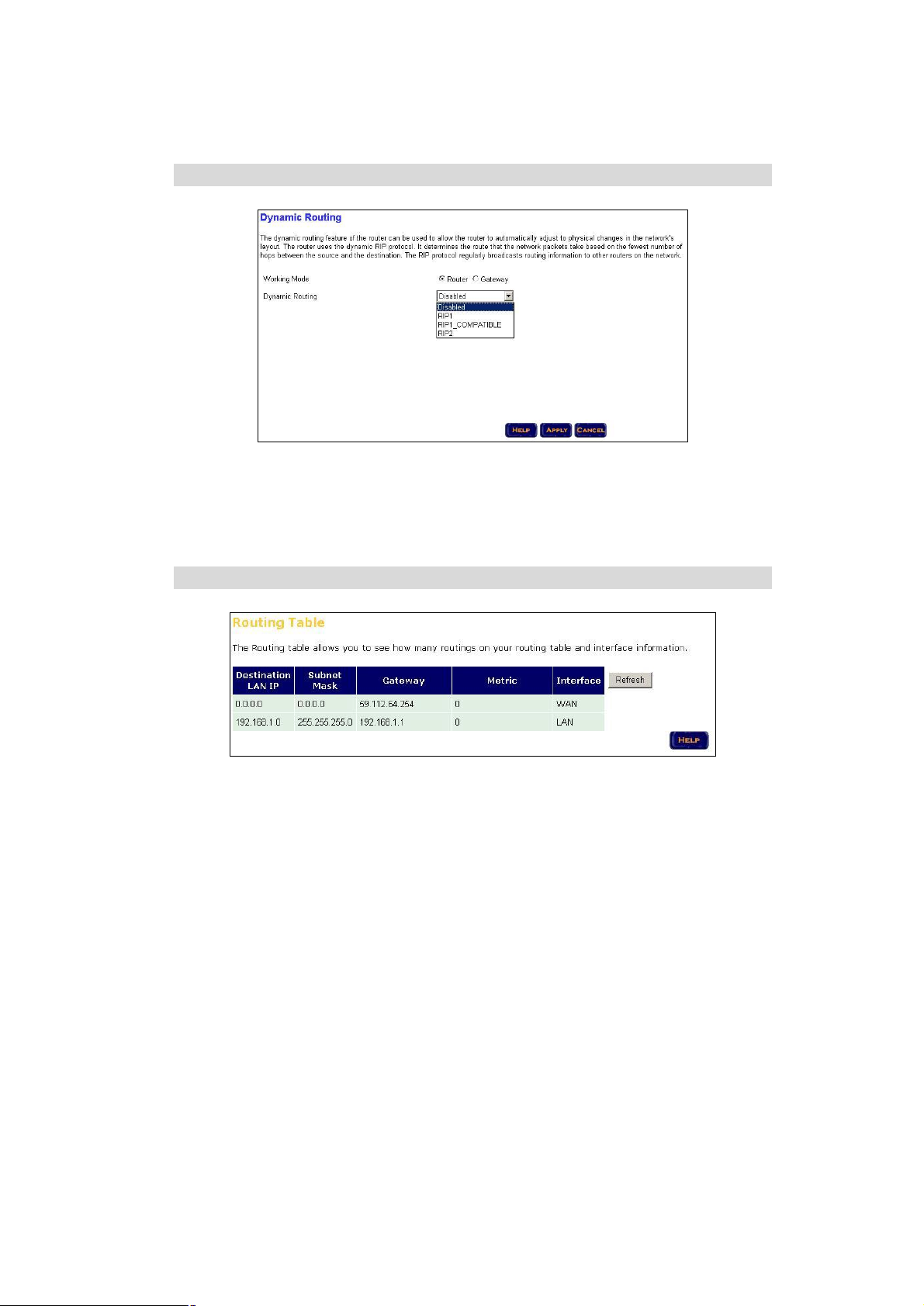
4.7.2 Dynamic Routing
The dynamic routing feature of the router can be used to automatically adjust to physical
changes in the network's layout. The router uses the dynamic RIP protocol. It determines the
route that the network packets take based on the fewest number of hops between the source
and the destination. The RIP protocol regularly broadcasts routing information to other routers
on the network.
4.7.3 Routing Table List
This page displays the information on your routing table.
22
Page 27

Chapter 5
Powerline Network Utility
5.1 Install the Powerline Network Utility
The Powerline Network Utility allows user to find devices on the powerline network, measure
data rate and ensure privacy by setting a user defined network private password. The installation procedure for the Powerline Network utility will vary depending on which operating system
you are using on your computer.
1. Insert the CD-ROM into the CD-ROM drive to initiate the autorun program. Once completed, a menu screen will appear.
2. Click on the “Powerline Network Utility” hyperlink to start the installation. If the menu
screen is not shown, you can start the installation as follows.
• Click on Start Menu/ Run.
• Enter “E:\Utility\setup.exe” in the appeared box, where “E” is the letter of your CD-
ROM drive.
• Click on “OK” button.
3. The utility will be installed into your computer and a new icon called “Powerline
Network Configuration Utility” will appear on your desktop.
5.2 Use the Powerline Network Utility
1. Double click the Powerline Network Configuration Utility icon shown on your desktop.
The Device tab shows the chipset and the MAC address of your Powerline device connected to your computer. If you have installed more than two Powerline devices, select the
preferred one and click Connect to access your network. Click Refresh whenever you add
or eliminate Powerline devices. The Link Quality depends on the site’s power circuit condition, power stability, etc.
23
Page 28

2. The Network tab shows all Powerline devices present on your network. Click Scan Power-
line Network to update Powerline network.
3. The Security tab shows the default network password is HomePlug. Enter your own
private network password if needed and click Set Local.
24
Page 29
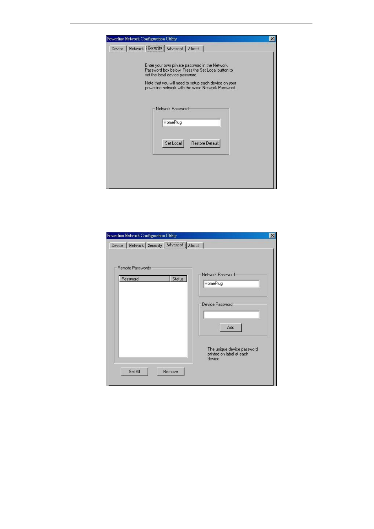
4. The Advanced tab allows you to add other remote device password. You don’t need this
password unless other devices set different network password with yours. Each device
password is different and listed on the bottom case label stuck on each Powerline Adapter.
Enter the device password (The format is xxxx-xxxx-xxxx-xxxx) and click Add. Click Set All
to activate the new-added password and the status column will be shown OK.
5. Click OK to close the Utility program.
25
Page 30

Appendix A
Troubleshooting
This chapter gives information about troubleshooting your PRT-301W. After each description, instructions are provided to help you diagnose and solve the issue.
LAN LED Not On
If the LAN LED does not light when the Ethernet connection is made, check the following:
- Be sure you are using the correct cable.
- Make sure that the Ethernet cable connections are secure at the Router and at the
hub or workstation.
- Make sure that power is turned on to the connected hub or workstation.
- If you are connecting a LAN port of PRT-301W directly to the uplink (MDI) port of a
hub, use the straight-through network cable.
- If you are connecting a LAN port of PRT-301W to a normal (MDI-X) hub port, use the
crossover network cable.
- If you are connecting a WAN port of PRT-301W to a normal (MDI-X) hub port, use
the straight-through cable.
Troubleshooting the ISP Connection
If your Router is unable to access the Internet, you should first determine
whether the Router is able to obtain a WAN IP address from the ISP. Unless
you have been assigned the static IP address, your Router must request an
IP address from the ISP. You can determine whether the request was successful using the Browser interface.
To check the WAN IP address from the Browser interface:
1. Launch your Browser and select an external site such as www.yahoo.com
2. Access the Main Menu of the Router's configuration at http://192.168.1.1
3. Click on Monitor
4. Check that an IP address is shown for the WAN Port
5. If it is "NO" on active table, your Router has not obtained an IP address from your ISP.
If your Router is unable to obtain an ISP address from the ISP, the problem may be one
of the following:
- Your Router may be set incorrectly the login name and password for PPPoE mode.
- Your ISP may check for your PC's Host Name. Assign the PC Host Name of your
ISP account to the Router as System Name, or as Host Name in the browser-based
Setup Wizard.
- Your ISP only allows one MAC address to connect to Internet, and may check for
your PC's MAC address. Inform your ISP that you have bought a new network device,
and ask them to use the Router's MAC address.
If your Router can obtain an IP address, but your PC is unable to load any web pages
from the Internet:
- Your PC may not recognize any DNS server addresses.
A DNS server is a host on the Internet that translates Internet names (such as www
addresses) to numeric IP addresses. Typically your ISP will provide the addresses of
one or two DNS servers for your use. If you entered a DNS address during
the Router's configuration at NAT mode, reboot your PC and verify the DNS address.
26
Page 31

Alternatively, you may configure your PC manually with DNS addresses, as explained
in your operating system documentation.
- Your PC may not have the Router configured as its TCP/IP gateway. If your PC obtains its information from the Router by DHCP, reboot the PC and verify the gateway
address.
Testing the LAN Path to Your Router
You can ping the Router from your PC to verify that the LAN path to your
Router is set up correctly. To ping the Router from a PC running Windows 95,
Windows 98, or Windows NT:
- From the Windows toolbar, click on the Start button and select Run.
- In the field provided, type Ping followed by the IP address of the Router at the NAT
mode, as in this example:
ping 192.168.1.1
- Click on OK.
You should see a message like this one:
Pinging < IP address > with 32 bytes of data
If the path is working, you see this message:
Reply from < IP address >: bytes=32 time=NN ms TTL=xxx
If the path is not working, you see this message:
Request timed out
If the path is not functioning correctly, you could have one of the following problems:
Wrong physical connections
-Make sure the Local LAN LED is on.
-Check that the corresponding Link LEDs are on for your network interface card and
for the hub ports (if any) that are connected to your workstation and Router.
Wrong network configuration
- Verify that the Ethernet card driver software and TCP/IP software are both installed
and configured on your PC or workstation.
- Verify that the IP address for your Router and your workstation are correct and that
the addresses are on the same subnet.
Testing the Path from Your PC to a Remote Device
After verifying that the LAN path works correctly, test the path from your PC to a remote device:
From the Windows run menu, type PING -n 10 followed by the IP address of a remote
device such as your ISP's DNS server. If the path is functioning correctly, replies as in
the previous section are displayed.
If you do not receive replies:
Check that your PC has the IP address of your Router listed as the default gateway. If
the IP configuration of your PC is assigned by DHCP, this information will not be visible in the control panel network utility. Go to the Run... window and run winipcfg. The
IP address of the Router should appear as the Default Gateway.
- Check to see that the network address of your PC (the portion of the IP address
specified by the subnet mask) is different from the network address of the remote device.
- Check console to verify the WAN status. If the menu indicates the WAN status as
down, check that your ADSL line is connected and functioning.
- If your ISP assigned a host name to your PC, enter that host name as the Router
name.
27
Page 32

- Your ISP could be rejecting the Ethernet MAC addresses of all but one of your PCs.
Most broadband ISPs restrict access by only allowing traffic from the MAC address of
your Broadband Router, but some ISPs additionally restrict access to the MAC address of a single PC connected to that modem. If this is the case, you must configure
to allow the Router to "borrow" the MAC address from the authorized PC.
28
 Loading...