

Page 1
1. Package Contents
Thank you for purchasing PLANET 1-port IEEE 802.3at PoE+ to
2-port IEEE 802.3af/at Gigabit PoE Extender, POE-E202. “Gigabit
PoE Extender” mentioned in this manual refers to the POE-E202.
Open the box of the Gigabit PoE Extender and carefully unpack it.
The box should contain the following items:
Gigabit PoE Extender x 1 User’s Manual x 1
If any of these are missing or damaged, please contact your dealer
immediately; if possible, retain the carton including the original
packing material, and use them again to repack the product in case
there is a need to return it to us for repair.
2. Product Features
Physical Port
3-port 10/100/1000BASE-T Gigabit RJ45 interface
- 1-port data + power input
- 2-port data + power output
Made of metal, desktop size design
Wall-mountable, Plug-and-Play installation
0 ~ 50 degrees C operating Temperature
PSE (Power Sourcing Equipment) is a device
(switch or hub for instance) that will provide power in
a PoE setup. The maximum allowed continuous output
power per such device in IEEE 802.3af is 15.4 watts
and in IEEE 802.3at is 30 watts.
Note
PD (Powered Device) such as IP phones, network
cameras or wireless access points is a PoE-enabled
terminal by PSE and thus it consumes energy.
3.ProductSpecications
Model POE-E202
Interfaces
PoE IN
PoE OUT
1 x 10/100/1000BASE-T Ethernet with IEEE
802.3at PoE “Data + DC” in auto MDI/MDI-X,
auto-negotiation RJ45 connector
2 x 10/100/1000BASE-T Ethernet with IEEE
802.3at/802.3af PoE “Data + DC” out
auto MDI/MDI-X, auto-negotiation RJ45
connector
PoE IN Port:
PoE-in-Use x 1 (orange), LNK/ACT x 1 (green)
LED Indicators
Protection
Enclosure Metal
Installation Wall mountable
Dimensions
(W x D x H)
Weight 234g
Power
Requirements
Power Consumption
Network Cable
PoE Out Port 1:
PoE-in-Use x 1 (orange), LNK/ACT x 1 (green)
PoE Out Port 2:
PoE-in-Use x 1 (orange), LNK/ACT x 1 (green)
ESD (Ethernet): 2KV (TBD)
Surge (EFT for power) : 2KV (TBD)
140 x 77 x 28 mm
IEEE 802.3at compliant with voltage within
52V-56V DC
1.6 watts/5.5BTU (System on with PoE input)
2.2 watts/7.5BTU (Ethernet full loading
without PoE function)
36 watts/122.8BTU (Full loading with PoE
function)
10BASE-T: 4-pair UTP Cat. 5 up to 100m
(328ft)
100BASE-TX: 4-pair UTP Cat. 5 up to 100m
(328ft)
1000BASE-T: 4-pair UTP Cat. 5e, 6, up to
100m (328ft)
EIA/TIA-568 100-ohm STP (100m, 328ft)
10/100/1000T
POE-E202
Figure 1: POE-E202
1 2
PoE OUT PoE IN
PoE Extender
PoE In-use
ACTLNK
- 1 -
Power over Ethernet
1-port data + power input
- Complies with IEEE 802.3at Power over Ethernet Plus
end-span/mid-span PD
- Supports PoE input power up to 30.8 watts
2-port data + power output
- Complies with IEEE 802.3af/IEEE 802.3at Power over
Ethernet/end-span PSE
- Up to 2 IEEE 802.3af/802.3at devices powered
- Supports PoE power up to 25 watts for each PoE port
- Auto detects powered device (PD)
Extends the range of PoE to an additional 100 meters (328ft.)
Forwards both Ethernet data and PoE power to remote device
Layer 2 Features
Hardware based 10/100/1000Mbps auto-negotiation and auto
MDI/MDI-X
Integrates address look-up engine, supporting 2K absolute MAC
addresses
10K Jumbo packet support
IEEE 802.1Q VLAN transparency
Features Store-and-Forward mode with wire-speed ltering and
forwarding rates
IEEE 802.3x ow control for full duplex operation and back-
pressure for half duplex operation
Automatic address learning and address aging
Supports CSMA/CD protocol
Case and Installation
No external power cable installation required
- 3 -
Power over Ethernet
PoE In Port
IEEE 802.3at Power over Ethernet Plus endspan/mid-span PD class 4 PD
PoE Standard
PoE Power Supply
Type
PoE Power
Power Pin
Assignment
Hardware Specications
Data Rate 10/100/1000Mbps
MAC Address Table 2K
Data Buffer 2Mbits
Switch Architecture Store-and-Forward
Switch Fabric 6Gbps
Switch Throughput 4.46Mpps @ 64 bytes
Jumbo Frame 10KB
Flow Control
Per PoE Out Port
IEEE 802.3at Power over Ethernet Plus endspan PSE
IEEE 802.3af Power over Ethernet end-span
PSE
End-span (Type A)
PoE In Port
52~56V DC, max. 30.8 watts
Per PoE Out Port
44~55V DC, max. 25 watts
PoE In Port
1/2 (+), 3/6 (-); 4/5 (+), 7/8 (-)
Per PoE Out Port
1/2 (+), 3/6 (-)
IEEE 802.3x pause frame for full duplex
Back pressure for half duplex
- 5 -
Standard Conformance
Regulatory
Compliance
Standard
Compliance
Environment
Operating
Storage
Note
Distance will often be shorter due to power delivery
voltage-drop on the wire. The maximum distances will
vary on the quality of the UTP cable and environment.
FCC Part 15 Class A, CE
IEEE 802.3 10BASE-T Ethernet
IEEE 802.3u 100BASE-TX Fast Ethernet
IEEE 802.3ab 1000BASE-T Gigabit Ethernet
IEEE 802.3af Power over Ethernet
IEEE 802.3at Power over Ethernet Plus
IEEE 802.3x Flow Control
Temperature: 0 ~ 50 degrees C
Relative Humidity: 5 ~ 95% (non-condensing)
Temperature: -10 ~ 70 degrees C
Relative Humidity: 5 ~ 95% (non-condensing)
4. Hardware Introduction
The front panel of the Gigabit PoE Extender consists of one autosensing 10/100/1000BASE-T 802.3at PoE IN port, and two autosensing 10/100/1000BASE-T 802.3af/802.3at PoE Out ports. The
LED Indicators are also located on the port of Gigabit PoE Extender
front panel.
- 7 -
4.2 Ports Connection
Connect the PoE IN port from the following
802.3at PSE devices through a Cat 5/5e/6 UTP
PoE IN Port
PoE OUT Port
cable:
PoE injector
PoE injector hub
PoE Ethernet switch
Connect the PoE OUT port to the following
802.3at/af PD devices through a Cat 5/5e/6 UTP
cable:
PoE IP camera
PoE VoIP phone
PoE wireless AP
PoE splitter
4.3 LED Indicators
802.3at PoE IN Port
LED Color Function
PoE-in-Use Orange
10/100/1000
LNK/ACT
Green
Lights to indicate the port is receiving
52V-56V DC in-line power input.
Lights to indicate the link through
that port is successfully established at
10/100/1000Mbps.
Blinks to indicate that the port is actively
sending or receiving data.
- 2 -
- 4 -
- 6 -
- 8 -
Page 2
802.3at/af PoE Out Ports
PoE PTZ IP Camera
PoE+(30W
)
IEEE 802.3at(25W
)
25W
Power
Data
100m
PoE Injector/Switch
802.3at PoE Extender
100m
1 In 1 Out
LED Color Function
PoE-in-Use Orange
Lights to indicate the port is providing
52V-56V DC in-line power output.
Lights to indicate the link through
10/100/1000
LNK/ACT
Green
that port is successfully established at
10/100/1000Mbps.
Blinks to indicate that the port is actively
sending or receiving data.
5. Hardware Installation
Note
1. When the PoE-in-use LED turns steady orange, it
means the Gigabit PoE Extender is being powered
successfully with PoE.
2. If the PoE-in-use LED is not lit, please check the
remote PSE or the cable connecting to a PC or a
network device to see if the cable is correct. Or
with an 802.3at device such as the target PD,
check whether the power injection is correct.
Never connect any non-standard POE PSE to the
Gigabit PoE Extender; it will damage the device
permanently.
5.1 Before Installation
The POE-E202 is installed between the PSE (Power Source
Equipment) and the PD (Powered Device); it is powered by PSE and
forwards the Ethernet data and remaining POE power to the PD.
The POE-E202 doesn’t require an external power supply and it can
be installed easily by just plug and play without affecting the data
transmission performance.
1. To provide you with better PoE power and data
extension quality, we strongly recommend that
you use “Solid UTP Cable” when installing the
POE-E202.
Note
2. The POE-E202 can be installed with a third-party
device if the device complies with IEEE 802.3at/af
standard.
- 9 -
5.2 Connecting POE-E202 to Power Source
Equipment (PSE)
This section describes how to install Gigabit PoE Extender and make
connection to it. Please read the following topics and perform the
procedures in the order being presented.
There are 3 RJ45 ports in the Gigabit PoE Extender, of which the
“PoE IN” port functions as “PoE (Data and Power) input” and
the two “PoE Out” ports function as “PoE (Data and Power)
output”.
Step 1: Connect a standard Cat5e/6 UTP cable from power
Step 2: The PSE delivers both Ethernet Data and PoE power
source equipment (PSE), such as PoE switch, PoE
injector hub and single port PoE injector, to the “PoE IN”
port of the Gigabit PoE Extender.
UTP
POE-E202
10/100/1000T
1 2
PoE OUT PoE IN
PoE
PoE Extender
PoE In-use
ACTLNK
PSE 802.3at PoE Switch
over UTP cable to the Gigabit PoE Extender and the
“PoE-in-use” and “LNK/ACT LED” will be lit steadily.
5.3 Connecting POE-E202 to Powered Device (PD)
Step 1: Connect the additional Cat5e/6 cable that will be used
Step 2: The “PoE Out” port is also the power injector which
Step 3: Once the Gigabit PoE Extender detects the existence of an
to connect to the remote Powered Device (PD) to the
“PoE Out” port of the Gigabit PoE Extender.
UTP
PoE
PoE Extender
PoE In-use
ACTLNK
PSE 802.3at PoE Switch
PoE Wireless AP
PoE Camera
POE-E202
UTP
PoE
10/100/1000T
1 2
PoE OUT PoE IN
UTP
PoE
- 11 -
transmits DC voltage to the Cat5e/6 cable and transfer
data and power simultaneously between the PSE and PD.
IEEE 802.3at/af device, the “PoE-in-Use” LED indicator
will be lit steadily, showing it is providing power.
1. If the connected device is not fully complying with
IEEE 802.3af/at standard or in-line power device,
the PoE-in-Use LED indicator of the Gigabit PoE
Extender will not be lit steadily.
Note
2. According to IEEE 802.3af/at standard, the Gigabit
PoE Extender will not inject power to the cable
if not connected to a standard IEEE 802.3af/at
device.
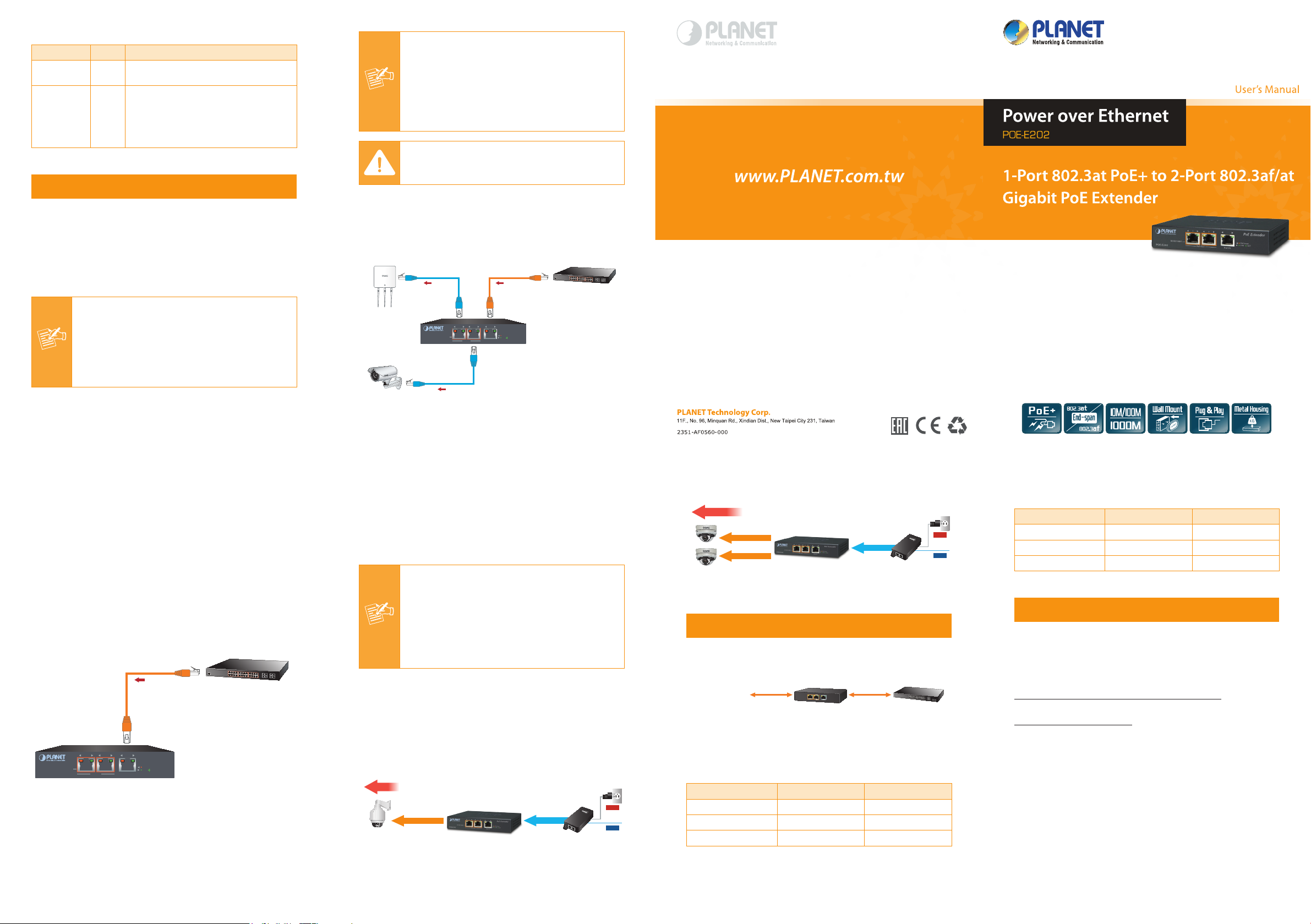
5.4 PoE Power Distribution
The POE-E202 can obtain a maximum of 36-watt PoE power from
802.3at PoE input port and supplies a maximum of 30-watt PoE
power budget to 2 PoE output ports, extending both the reach of
Gigabit Ethernet Data and IEEE 802.3at/802.3af Power over
Ethernet over the standard 100m (328 ft.) Cat 5/5e/6 UTP cable to
up to 200m at the same time.
25W
PoE PTZ IP Camera
IEEE 802.3at(25W
100m
)
1 In 1 Out
802.3at PoE Extender
PoE+(30W
100m
)
PoE Injector/Switch
Power
Data
12W+12W
PoE Dome IP Camera
IEEE 802.3af(12W
100m
IEEE 802.3af(12W
100m
)
)
1 In 2 Out
802.3at PoE Extender
PoE+(30W
100m
)
PoE Injector/Switch
Power
Data
6. Power over Ethernet Capability
With different distance and different PoE input source, it will inect
the PoE output capability. Please refer to the table below.
PoE Output Capacity
POE-E202
6.1 When PSE/PoE Switch output is DC 52V
A (Distance) B (Distance) C (Watts)
100M 20M 21.6
100M 60M 20.7
100M 100M 19.7
(A)(B)(C)
PSE 802.3at PoE Switch
(A): Distance
(B): Distance
(C): Watts
6.2 When PSE/PoE Switch output is DC 56V
A (Distance) B (Distance) C (Watts)
100M 20M 21.1
100M 60M 20.2
100M 100M 19.3
7. Customer Support
Thank you for purchasing PLANET products. You can browse our
online FAQ resource at PLANET web site rst to check if it could
solve your issue. If you need more support information, please
contact PLANET switch support team.
PLANET online FAQ:
http://www.planet.com.tw/en/support/faq.php?type=1
Switch support team mail address:
support_switch@planet.com.tw
Copyright © PLANET Technology Corp. 2016.
Contents are subject to revision without prior notice.
PLANET is a registered trademark of PLANET Technology Corp. All other
trademarks belong to their respective owners
- 10 -
- 12 - - 13 - - 14 -
 Loading...