

Page 1
User's Manual
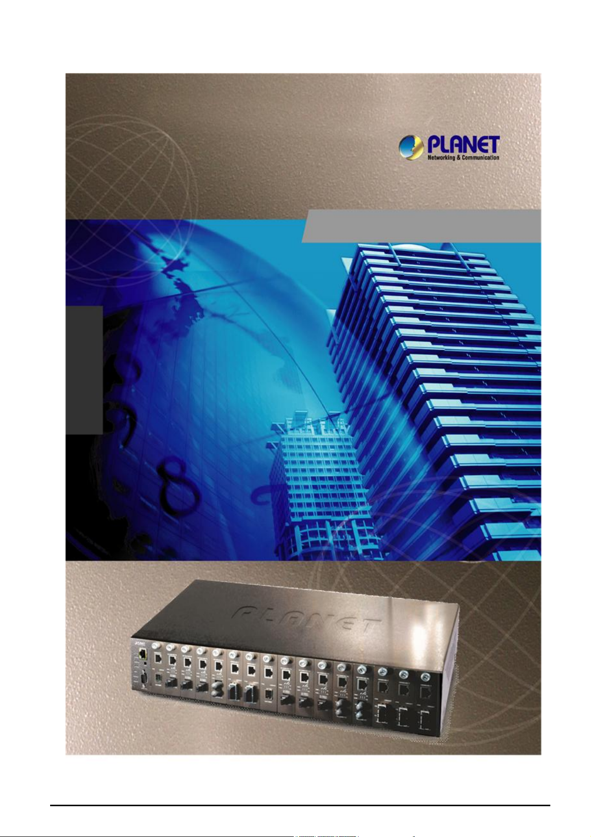
MC-1600MR
MC-1600MR48
16-Slot Web Smart Media
Converter Chassis
- 1 -
Page 2

Trademarks
Copyright © PLANET Technology Corp. 2007.
Contents subject to revision without prior notice.
PLANET is a registered trademark of PLANET Technology Corp. All other trademarks belong to their respective
owners.
Disclaimer
PLANET Technology does not warrant that the hardware will work properly in all environments and applications,
and makes no warranty and representation, either implied or expressed, with respect to the quality, performance,
merchantability, or fitness for a particular purpose.
PLANET has made every effort to ensure that this User’s Manual is accurate; PLANET disclaims liability for any
inaccuracies or omissions that may have occurred.
Information in this User’s Manual is subject to change without notice and does not represent a commitment on the
part of PLANET. PLANET assumes no responsibility for any inaccuracies that may be contained in this User’s
Manual. PLANET makes no commitment to update or keep current the information in this User’s Manual, and
reserves the right to make improvements to this User’s Manual and/or to the products described in this User’s
Manual, at any time without notice.
If you find information in this manual that is incorrect, misleading, or incomplete, we would appreciate your
comments and suggestions.
FCC Warning
This equipment has been tested and found to comply with the limits for a Class A digital device, pursuant to Part
15 of the FCC Rules. These limits are designed to provide reasonable protection against harmful interference
when the equipment is operated in a commercial environment. This equipment generates, uses, and can radiate
radio frequency energy and, if not installed and used in accordance with the Instruction manual, may cause
harmful interference to radio communications. Operation of this equipment in a residential area is likely to cause
harmful interference in which case the user will be required to correct the interference at his own expense.
CE Mark Warning
This is a Class A product. In a domestic environment, this product may cause radio interference, in which case the
user may be required to take adequate measures.
WEEE Warning
To avoid the potential effects on the environment and human health as a result of the presence of
hazardous substances in electrical and electronic equipment, end users of electrical and electronic
equipment should understand the meaning of the crossed-out wheeled bin symbol. Do not dispose of
WEEE as unsorted municipal waste and have to collect such WEEE separately.
Revision
PLANET Web Smart Media Converter Chassis User’s manual
MODEL: MC-1600MR / MC-1600MR48
REVISION: 1.0 (MARCH.2007)
Part No.: EM-MC1600M_v1.0 (2080-AA3450-000)
- 2 -
Page 3

TABLE OF CONTENTS
1. INTRODUCTION.......................................................................................................................................... 4
1.1 PACKAGE CONTENTS ................................................................................................................................. 4
1.2 HOW TO USE THIS MANUAL ........................................................................................................................4
1.3 ABOUT THE WEB SMART MEDIA CONVERTER CHASSIS ................................................................................ 5
1.4 FEATURES ................................................................................................................................................. 5
1.5 SPECIFICATION .......................................................................................................................................... 6
2. HARDWARE INSTALLATION ....................................................................................................................7
2.1 FRONT PANEL ............................................................................................................................................ 7
2.2 REAR PANEL.............................................................................................................................................. 8
2.3 WEB SMART MEDIA CONVERTER CHASSIS INSTALLATION............................................................................. 9
3. WEB SMART MEDIA CONVERTER CHASSIS MANAGEMENT............................................................ 13
3.1 OVERVIEW ............................................................................................................................................... 13
3.2 MANAGEMENT METHODS .......................................................................................................................... 13
3.2.1 Local Console Management...........................................................................................................13
3.2.2 Web Management...........................................................................................................................14
3.3 ASSIGNING AN IP ADDRESS TO THE WEB SMART MEDIA CONVERTER CHASSIS ...........................................14
3.4 LOGGING ON TO THE WEB SMART MEDIA CONVERTER CHASSIS ................................................................. 15
4. CONSOLE INTERFACE............................................................................................................................16
4.1 CONNECT TO PC ................................................................................................................................. 16
4.2 LOGIN IN .................................................................................................................................................. 17
4.3 MAIN MENU SCREEN ................................................................................................................................17
4.4 GETTING STARTED ................................................................................................................................... 18
4.4.1 General Guidelines.........................................................................................................................18
4.4.2 Show command..............................................................................................................................19
4.4.3 Set command..................................................................................................................................23
4.4.4 Factory default................................................................................................................................27
4.4.5 Reboot.............................................................................................................................................28
4.4.6 Logout.............................................................................................................................................29
5. WEB MANAGEMENT.................................................................................................................................30
5.1 LOGIN IN TO THE WEB SMART MEDIA CONVERTER CHASSIS ....................................................................... 30
5.2 CHASSIS STATUS .....................................................................................................................................31
5.3 CONVERTER STATUS................................................................................................................................32
5.4 SYSTEM CONFIGURATION ......................................................................................................................... 34
5.5 LOCATION SETTING ..................................................................................................................................37
5.6 REDUNDANT BACKUP SETTING ................................................................................................................. 38
5.7 PASSWORD SETTING ................................................................................................................................39
5.8 FIRMWARE UPGRADE ............................................................................................................................... 41
5.9 RESTORE SYSTEM DEFAULT .....................................................................................................................44
5.10 REBOOT SYSTEM ................................................................................................................................... 45
5.11 LOGOUT................................................................................................................................................. 46
6. LINK PASS THROUGH FUNCTION......................................................................................................... 48
6.1 LINK LOSS CARRY FORWARD (LLCF)........................................................................................................ 48
6.2 LINK LOSS RETURN (LLR) ........................................................................................................................ 49
7. TROUBLESHOOTING................................................................................................................................50
APPENDIX A NETWORKING CONNECTION...............................................................................................51
A.1 SWITCH‘S RJ-45 PIN ASSIGNMENTS ......................................................................................................... 51
A.2 RJ-45 CABLE PIN ASSIGNMENT .................................................................................................................51
- 3 -
Page 4

1. INTRODUCTION
1.1 Package Contents
Thank you for purchasing PLANET Web Smart Media Converter Chassis, the Web Smart Media Converter Chassis
package shall contain following contents:
Check the contents of your package for follow i ng parts:
z Web Smart Media Converter Chassis with one power supply installed x1
z User's manual CD x1
z Quick Installation Guide x1
z RS-232 console cable x1
z Power Cord x1
z Two Rack-Mounting Brackets with attachment screws x1
If any of these pieces are missing or damaged, please contact your dealer immediately, if possible, retain the carton
including the original packing material, and use them against to repack the product in case there is a need to return it to
us for repair.
1.2 How to Use This Manual
The Web Smart Media Converter Chassis User’s Manual is structured as followings:
Section 2, Hardware Installation
It explains the functions of Web Smart Media Converter Chassis and how to install the Web Smart Media Converter
Chassis.
Section 3, Web Smart Media Converter Chassis Management
It contains information about how to manage the Web Smart Media Converter Chassis.
Section 4, Console Interface
It contains information about the smart function from the console interface of Web Smart Media Converter Chassis.
Section 5, Web Management
It contains information about the smart function from the Web interface of Web Smart Media Converter Chassis.
Section 6, Link Pass Through Function
It contains detail explanation about the Link Pass Through function.
Section 7, Troubleshooting
It contains troubleshooting guide of Web Smart Media Converter Chassis.
Appendix A
It contains cable information of Web Smart Media Converter Chassis.
In the following section, the term “Web Smart Media Converter Chassis” means the MC-1600MR and MC-1600MR48.
- 4 -
Page 5

1.3 About the Web Smart Media Converter Chassis
The Web Smart Media Converter Chassis provides one management module and 16-Slots for optional FST-8/ GST-7
series Fast / Gigabit Ethernet Smart Media converter installation, with hot-swappable feature and the redundant link
function to avoid entire network down time. Its management function allows network administrators to monitor the slide in
connection status of converter module and configures the converter module via local console port and remote Web interface.
The MC-1600MR equip with one 100~240V AC power supply unit and MC-1600MR48 equip with one DC -48V power
supply unit on its standard package, both MC-1600MR and MC-1600MR48 provide one spare power supply unit slot for
option redundant power supply installation. A redundant power supply is also provided to enhance the reliability with options of either 100~240V AC power supply unit or DC -48V power supply unit.
1.4 Features
◆ High quality 19”Rack-Mountable Chassis installation
◆ Supports up to sixteen hot-swappable slide-in modular media converter
◆ One 10/100Mbps Fast Ethernet port and one RS-232 port for management
◆ Two power slots at rear panel for redundant power support with options of 100~240V AC or -48V DC supply
◆ Reduces the effort of converter’s maintenance and management
◆ LED indicators for system and fan status, up to two fans installation of increased air-flow for system cooling
◆ Supports the PLANET smart Fast Ethernet and Gigabit Ethernet Media Converter FST-8 and GST-7 series
◆ Auto-MDI / MDI-X for 10/100Base-TX port
◆ Manageable through local console and remote Web interface
◆ EMI standards comply with FCC, CE class A
- 5 -
Page 6
1.5 Specification
Model MC-1600MR MC-1600MR48
Hardware Specification
Dimension (W x D xH) 440 x 88 x 350mm, 2U
Slot 16 open converter slots (115 x 80 x 26mm, W x D x H)
2 power slot s (one fixed, one vacant* )
Power requirement 100-240V AC, 1.5A, 50-60Hz DC -48V, 2A
Power Output 5V DC per slot, 2A maximum
Power consumption 8.4 Watts / 28BTU (1 x power supply , not
include converters)
120 Watts / 409BTU ( Full loading)
Operate environment 0~50 Degree C, 5%~90%RH
Storage environment -20~70 Degree C, 5%~90%RH
Emission FCC Class A, CE mark
Management Interface
Standards IEEE 802.3 10Base-T Ethernet, IEEE 802.3u 100Base-TX Fast Ethernet, IEEE 802.3x
Flow control
Fixed interface 10/100Base-TX port , RS-232 console port x1, Reset button x1
Speed Ethernet: 10/20Mbps for half / full-duplex, Fast Ethernet: 100/200Mbps for half / full-duplex
LED indicator System: MGM, Console: LNK/ACT, PWR ON x2, PWR FAIL x2, FAN FAIL x2
5.3 Watts / 18BTU (1 x power supply, not include converters)
96 Watts / 327 BTU ( Full loading)
Remark: The device comes with one build in power module, to install the second power module into the vacant power slot, please consult
your local dealer.
- 6 -
Page 7
2. HARDWARE INSTALLATION
This section describes the functionalities of MC-1600MR / MC-1600MR48 components and guides how to install the device
on the desktop or shelf. Basic knowledge of networking is assumed; please read this chapter completely before continuing
installs the Web Smart Media Converter Chassis.
2.1 Front Panel
The Web Smart Media Converter Chassis provides one management module and 16-Slots for optional FST-8/ GST-7
series Fast / Gigabit Ethernet Smart Media converter installation.
Figure 2-1: Web Smart Media Converter Chassis front panel
The LED indicators of the management module include power on, power fail, fan fail, MGM, Console and LNK/ACT. The
management module front panel in Figure 2-2 appears and the LED indicator in table 2-1 appears.
LED Indicators
LED Color LED Status Function
PWR ON
PWR FAIL
FAN FAIL
MGM
CONSOLE
LNK/ACT
Figure 2-2: Management module front panel
Green
Amber
Amber
Green
Green
Green
Table 2-1: LED Indicators from Management module front panel
Lights On Indicate that the device has power.
Lights Off Indicate that the device not receive power.
Lights On Indicate that power is inserted and failed to
work.
Lights Off Indicate that power is inserted and work
normal.
Lights On Indicate that fan is failed to work.
Lights Off Indicate that fan is work normally.
Light blink Indicate that CPU is working.
Light Off Indicate that CPU is not working.
Light blink Indicate that console port is working.
Light Off Indicate that console port is not working.
Light On The link through that port is successfully
established.
Light Off The link through that port is not established
or run at 10Mbps half / full duplex mode.
#
Notice:
Press the RESET button for 5 seconds, the Web Smart Media Converter Chassis will back to factory default mode; the
entire configuration will be erased.
- 7 -
Page 8
2.2 Rear Panel
The MC-1600MR equip with one 100~240V AC power supply unit and MC-1600MR48 equip with one DC -48V power
supply unit on its standard package, both MC-1600MR and MC-1600MR48 provide one spare power supply unit slot for
option redundant power supply installation. A redundant power supply is also provided to enhance the reliability with options of either 100~240V AC power supply unit or DC -48V power supply unit.
Figure 2-3: Rear panel of Web Smart Media Converter Chassis
Install and remove the power supply unit
To install a power supply unit to Web Smart Media Converter Chassis, please fasten the hand screw clockwise and slide in
the power supply unit to the Web Smart Media Converter Chassis.
To remove a power supply unit out the Web Smart Media Converter Chassis, please loose the hand screw counter
clockwise and pull out the power supply unit from the Web Smart Media Converter Chassis.
Figure 2-4: Install and remove the power supply unit of Web Smart Media Converter Chassis
Power Notice:
1. The device is a power-required device, it means, it will not work till it is powered. If your networks should active all the
time, please consider using UPS (Uninterrupted Power Supply) for your device. It will prevent you from network data
loss or network downtime.
2. In some area, installing a surge suppression device may also help to protect your Web Smart Media Converter Chassis
from being damaged by unregulated surge or current to the Web Smart Media Converter Chassis.
- 8 -
Page 9
2.3 Web Smart Media Converter Chassis Installation
The chapter describes how to install optional FST-8/ GST-7 series Fast / Gigabit Ethernet Smart Media converter into your
Web Smart Media Converter Chassis, please read the following topics and perform the procedures in the order being
presented.
To install your Web Smart Media Converter Chassis on a desktop or shelf, simply complete the following steps.
2.3.1 Desktop Installation
To install a Web Smart Media Converter Chassis on a desktop or shelf, simply completed the following steps:
Step 1: Attached the rubber feet to the recessed areas on the bottom of the Web Smart Media Converter Chassis.
Step 2: Place the Web Smart Media Converter Chassis on a desktop or shelf near an AC/DC power source.
Step 3: Keep enough ventilation space between the Web Smart Media Converter Chassis and the surrounding objects.
#Notice:
When choosing a location, please keep in mind the environmental restrictions discussed in Chapter 1, Section 5, Specification.
Step 4: Connect your Web Smart Media Converter Chassis to network administrator stations.
A. Connect one end of a standard network cable to the 10/100 RJ-45 port on the management module front panel of
the Web Smart Media Converter Chassis.
B. Start to manage the Web Smart Media Converter Chassis through the Microsoft Internet Explorer and etc.
#Notice:
Connection to the Web Smart Media Converter Chassis requires UTP Category 5 network cabling with RJ-45 tips. For
more information, please see the Cabling Specification in Appendix A.
Step 5: Supply power to the Web Smart Media Converter Chassis.
A. Connect one end of the power cable to the Web Smart Media Converter Chassis.
B. Connect the power plug of the power cable to a standard wall outlet then power on the Web Smart Media Converter
Chassis.
When the Web Smart Media Converter Chassis receives power, the Power LED should remain solid Green.
2.3.2 Rack Mounting
To install the Web Smart Media Converter Chassis in a 19-inch standard rack, follow the instructions described below.
Step 1: Place your Web Smart Media Converter Chassis on a hard flat surface, with the front panel positioned towards your
front side.
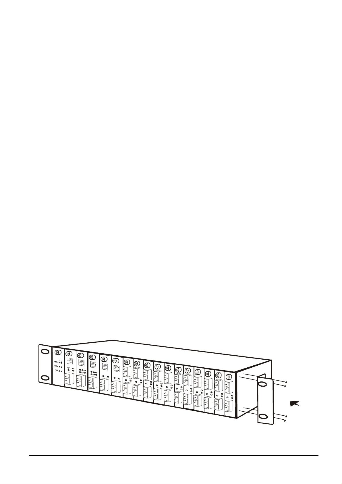
Step 2: Attach a rack-mount bracket to each side of the Web Smart Media Converter Chassis with supplied screws at-
tached to the package. Figure 2-5 shows how to attach brackets to one side of the Web Smart Media Converter
Chassis.
Figure 2-5 Attaching the brackets to the Web Smart Media Converter Chassis
- 9 -
Page 10
Caution:
You must use the screws supplied with the mounting brackets. Damage caused to the parts by using incorrect screws
would invalidate your warranty.
Step 3: Secure the brackets tightly.
Step 4: Follow the same steps to attach the second bracket to the opposite side.
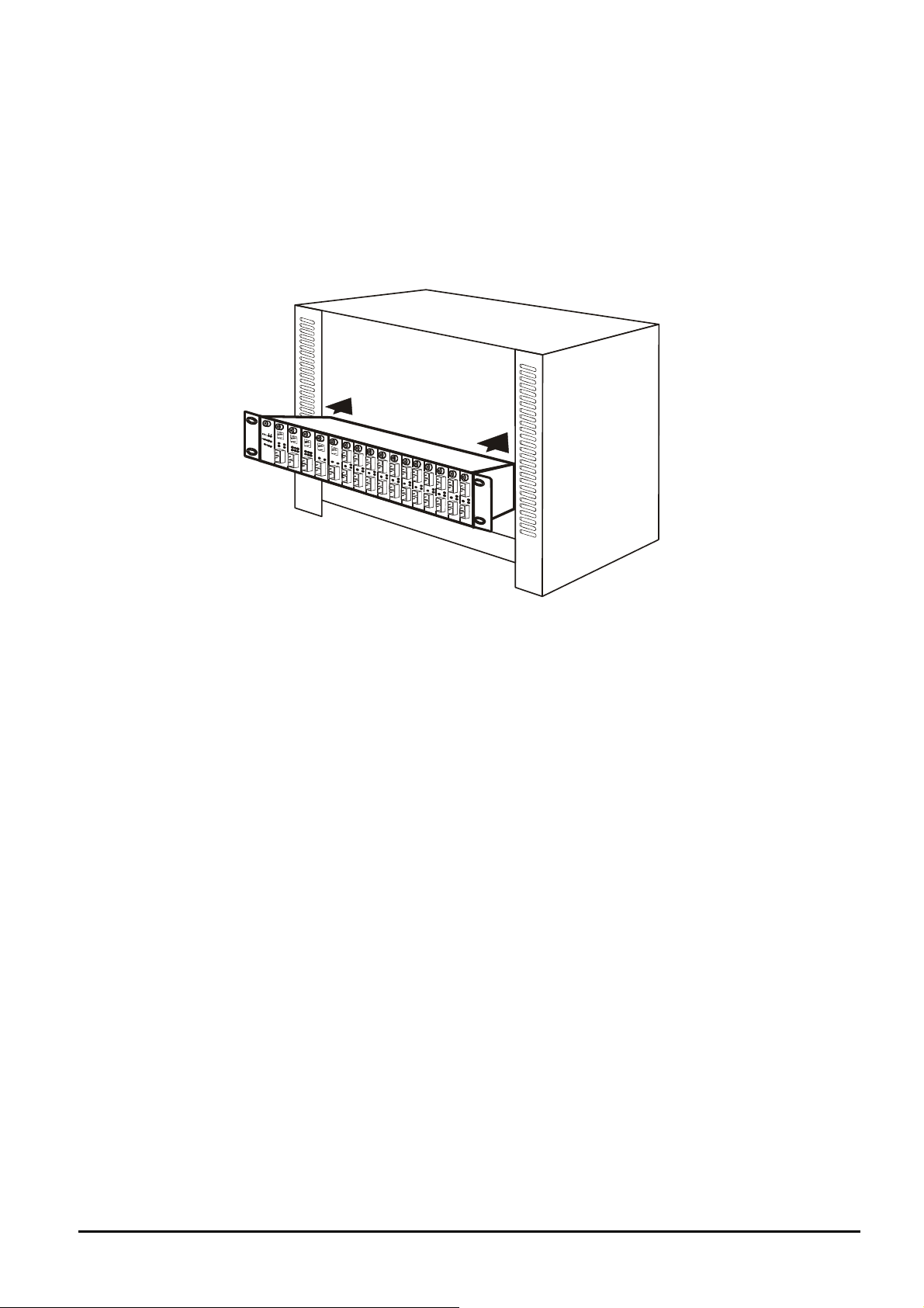
Step 5: After the brackets are attached to the Web Smart Media Converter Chassis, use suitable screws to securely attach
the brackets to the rack, as shown in Figure 2-6.
Figure 2-6 Mounting the Web Smart Media Converter Chassis in a Rack
Step 6: Proceed with the steps 4 and steps 5 of section 2.3.1 Desktop Installation to connect the network cabling and
supply power to your Web Smart Media Converter Chassis.
- 10 -
Page 11
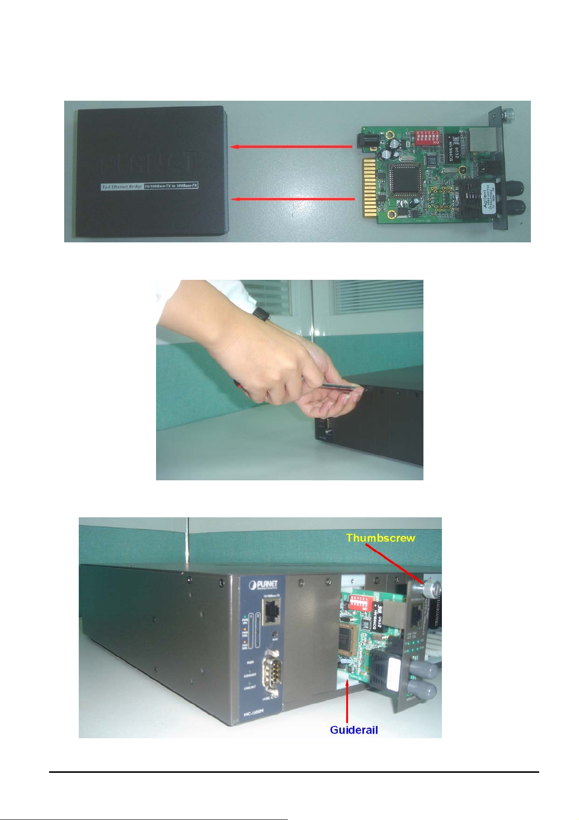
2.3.3 Slide Media Converter board into MC-1600MR /MR48 Chassis Installation
Step 1: unscrew and pull out the FST-80x /GST-70x Media Converter board.
Step 2: Remove a blank faceplate from an empty expansion slot on the front of the chassis. The FST-80x /GST-70x
Media Converter board can be installed in any expansion slot.
Step 3: Slide the FST-80x /GST-70x Media Converter board into the expansion slot, aligning it with the guide rails, until it
firmly connects to the chassis’ backplane.
Step 4: Secure the FST-80x /GST-70x Media Converter board to the chassis by tightening the thumbscrew.
- 11 -
Page 12
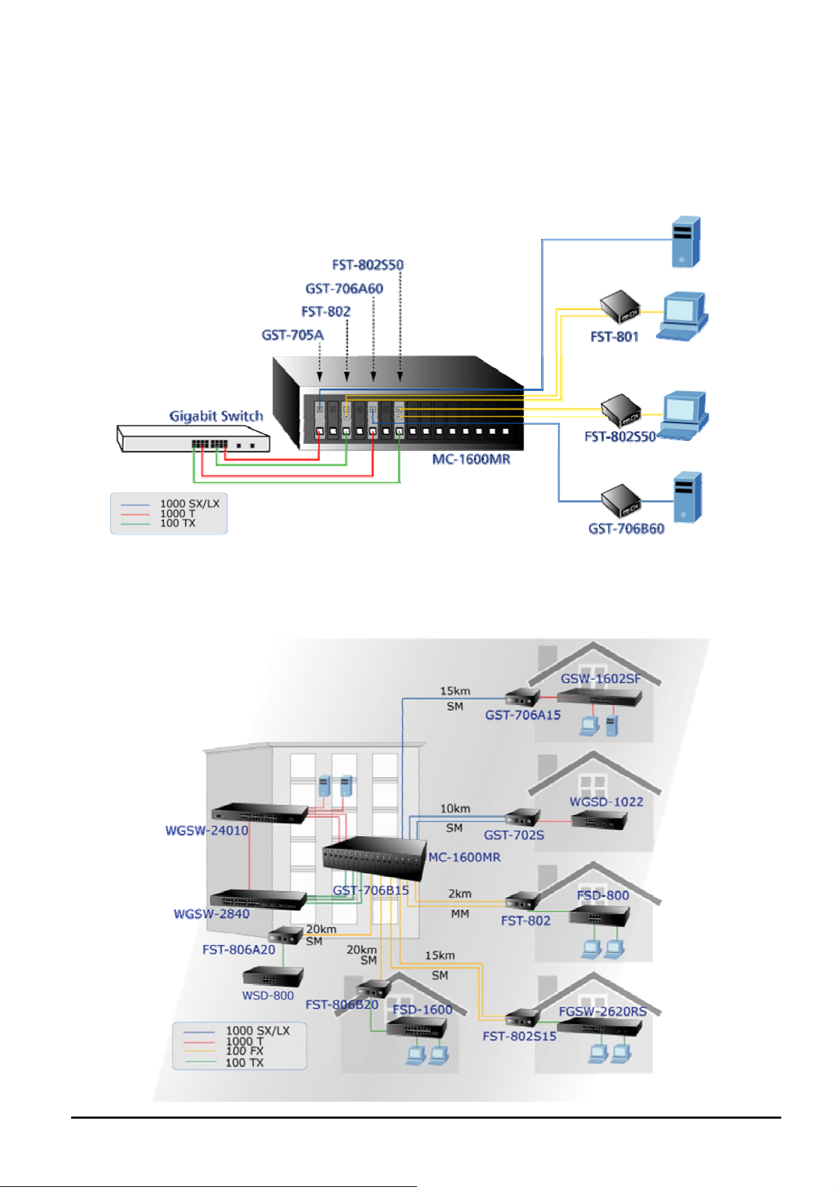
2.3.4 Centralize management Media Converter application
Affording the current network grows and expanding, the PLANET MC-1600MR/MC-1600R48 provide advanced Media
conversion technology to fill this kind of demands. The Web Smart Media Converter chassis allows installing up to sixteen
FST-8 / GST-7 series of Fast /Gigabit Ethernet Smart Media converter with diverse fiber connect types of options to meet
different network applications. It is very flexible for FST-8 / GST-7 series to install into the central Web Smart Media
converter chassis for centralized management.
Once, the FST-8 / GST-7 series of Fast /Gigabit Ethernet Smart Media converter install into Web Smart Media Converter
chassis with hot swappable feature and redundant link function to avoid entire network downtime. The PLANET Web
Smart Media Converter chassis with FST-8 / GST-7 series of Fast /Gigabit Ethernet Smart Media converter are the ideal
solution for building a network solution of FTTC (Fiber to the Curb) and FTTB (Fiber to the Building) for ISPs, campuses
and enterprises.
- 12 -
Page 13

3. WEB SMART MEDIA CONVERTER CHASSIS MANAGEMENT
This chapter describes how to manage the Web Smart Media Converter Chassis. Topics include:
- Overview
- Management methods
- Assigning an IP address to the Web Smart Media Converter Chassis
- Logging on to the Web Smart Media Converter Chassis
3.1 Overview
The Web Smart Media Converter Chassis provides a user-friendly, command line under console interface. Using this interface, you can perform various Web Smart Media Converter Chassis configuration and management activities, including:
Command Description
Show system Show software version, Mac address and IP address of Web Smart Media Converter Chassis.
Show IP Show current IP subnet address of Web Smart Media Converter Chassis.
Show power Show current power supply unit status of Web Smart Media Converter Chassis.
Show slot [n]
Show redundant [n] Show per redundant group status of Web Smart Media Converter Chassis.
Set slot [n]
Set redundant [n] disable /
enable
Set IP xxx.xxx.xxx.xxx,
mmm. mmm, mmm, mmm,
ggg.ggg.ggg.ggg
Set Pass [oldpass] [ newpass]
Factory Default Reset the Web Smart Media Converter Chassis to factory default mode.
Reboot Reboot the Web Smart Media Converter Chassis.
Logout Logout console interface of Web Smart Media Converter Chassis.
Please refer to the following Chapter 4 and 5 for the details.
Show current per slot status of Web Smart Media Converter Chassis with FST-8 / GST-7 Media
Converter boards.
Configure per slot setting of Web Smart Media Converter Chassis with various Media Converter boards.
Disable or enable per redundant group of Web Smart Media Converter Chassis.
Assign IP address, subnet mask, and gateway of Web Smart Media Converter Chassis.
Change the default password of Web Smart Media Converter Chassis, the maximum length is
8 characters.
3.2 Management Methods
There are two ways to manage the Web Smart Media Converter Chassis:
- Local Console Management via the serial port of Web Smart Media Converter Chassis.
- Web Management via a network or dial-up connection.
3.2.1 Local Console Management
You can manage the Web Smart Media Converter Chassis locally by connecting a VT100 terminal, or a personal computer
or workstation with terminal emulation software, to the serial port of Web Smart Media Converter Chassis. The terminal or
workstation connects to the serial port of Web Smart Media Converter Chassis. using a null modem cable that has the
appropriate connectors on each end.
This management method is ideal when:
- The network is unreliable.
- The Network Manager does not have direct network connection.
- 13 -
Page 14

The serial port of Web Smart Media Converter Chassis. default setting is set to 19200 baud using a character format of 8
data bits, no parity, and 1 stop bit.
Therefore, configure the terminal or workstation to use these settings before you log on to the Web Smart Media Converter
Chassis. You can change this default setting, if desired, after you log on.
3.2.2 Web Management
You can manage the Web Smart Media Converter Chassis remotely by having a remote host with web browser, such as
Microsoft Internet Explorer or Netscape Navigator.
Using this management method:
The Web Smart Media Converter Chassis must have an Internet Protocol (IP) address accessible for the remote host.
3.3 Assigning an IP Address to the Web Smart Media Converter Chassis
To manage the Web Smart Media Converter Chassis remotely through the web browser with a Management Station, you
must assign an IP address to the Web Smart Media Converter Chassis.
To set the IP address, please use “set ip xxx.xxx.xxx.xxx mmm.mmm.mmm.mmm ggg.ggg.ggg.ggg” command.
For example, to configure the Web Smart Media Converter Chassis with the following IP settings:
IP Address: 192.168.0.1
Subnet Mask: 255.255.255.0
Default Gateway: 192.168.0.254
Press the following command and press <Enter>
set ip 192.168.0.1 255.255.255.0 192.168.0.254
Then the following message appears under console interface:
The IP sets to 192.168.0.1
The netmask sets to 255.255.255.0
The gateway sets to 192.168.0.254
You can access the web interface of Web Smart Media Converter Chassis through the new IP address.
- 14 -
Page 15
3.4 Logging on to the Web Smart Media Converter Chassis
When you log on to the Web Smart Media Converter Chassis console port for the first time, a sign-on string appears and
you are prompted for a console login user name and password.
The factory default login username and password is admin.
#Notice:
1. For security reason, please change and memorize the new password after this first setup.
2. Only accept command in lowercase letter under console interface.
- 15 -
Page 16
4. CONSOLE INTERFACE
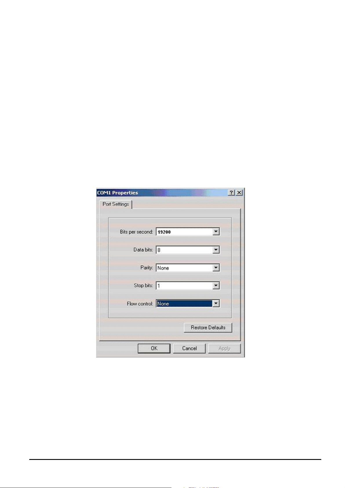
4.1 CONNECT TO PC
RS-232 serial cable
Use the bundled RS-232 serial cable and attach the 9-pin female connector to the male connector on the Web Smart
Media Converter Chassis. Plug the other side of this cable to your PC.
Hyper Terminal
In Windows 98/2000/ME/XP, launch “HyperTerminal”, create a new connection, and adjust settings as below:
Emulation: VT-100 compatible
Baud per second: 19200
Data bits: 8
Parity: None
Stop bits: 1
Flow Control: None
To gain a demo, please see the Figure 4-1.
Figure 4-1 Port Settings for console interface
- 16 -
Page 17
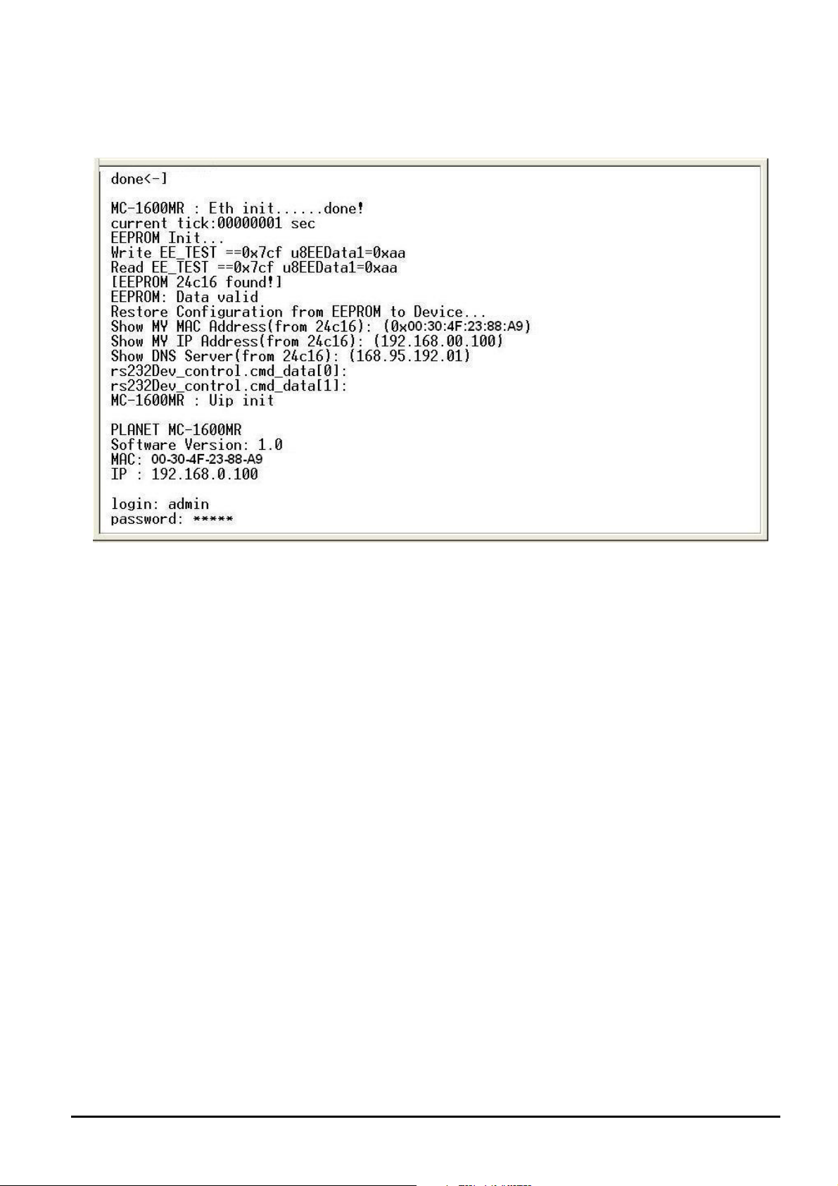
4.2 Login in
Login is required to access the console interface after the self-test completes successfully. The factory default user name
and password is "admin". You may change the password by use “set pass” command. Please always enter the correct
user name and password. (See Figure 4-2)
Figure 4-2 Web Smart Media Converter Chassis login screen
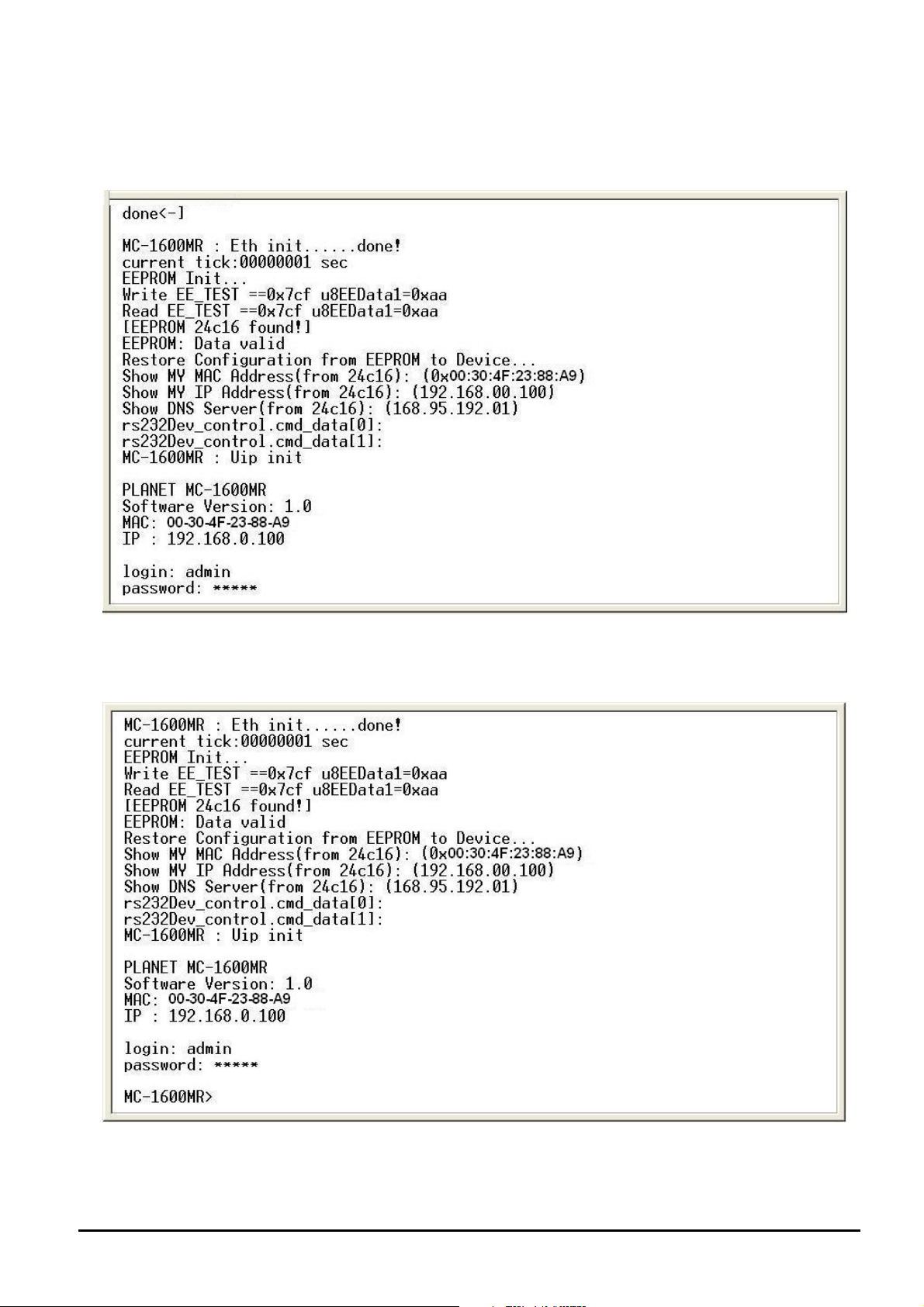
4.3 Main Menu screen
After login the Web Smart Media Converter Chassis, the main menu screen shows as below.
- 17 -
Figure 4-3 Web Smart Media Converter Chassis Main Menu screen
Page 18

4.4 Getting Started
4.4.1 General Guidelines
The Web Smart Media Converter Chassis allows users to configure the device via command line under console interface.
Please type “help” or “?” for all available commands in the”MC-1600MR>” prompt. The screen of available commands in
Figure 4-4 appears, and the detail description shown in table 4-1.
Figure 4-4 Web Smart Media Converter Chassis available commands screen
Command Description
Show system Show software version, Mac address and IP address of Web Smart Media Converter Chassis.
Show IP Show current IP subnet address of Web Smart Media Converter Chassis.
Show power Show current power supply unit status of Web Smart Media Converter Chassis.
Show slot [n]
Show redundant [n] Show per redundant group status of Web Smart Media Converter Chassis.
Set slot [n]
Set redundant [n] disable /
enable
Set IP xxx.xxx.xxx.xxx,
mmm. mmm, mmm, mmm,
ggg.ggg.ggg.ggg
Set Pass [oldpass] [ newpass]
Factory Default Reset the Web Smart Media Converter Chassis to factory default mode.
Reboot Reboot the Web Smart Media Converter Chassis.
Show current per slot status of Web Smart Media Converter Chassis with FST-8 / GST-7 Media
Converter boards.
Configure per slot setting of Web Smart Media Converter Chassis with various Media Converter boards.
Disable or enable per redundant group of Web Smart Media Converter Chassis.
Assign IP address, subnet mask, and gateway of Web Smart Media Converter Chassis.
Change the default password of Web Smart Media Converter Chassis, the maximum length is
8 characters.
Logout Logout console interface of Web Smart Media Converter Chassis.
Table 4-1 Detail description of Web Smart Media Converter Chassis available commands
#Notice: Only accept command in lowercase letter under console interface.
- 18 -
Page 19

4.4.2 Show command
From the main menu screen (see Figure 4-3), input “show” and press enter. The show command list screen in Figure 4-5
appears.
This show command list contains five items:
Show system: Please refer to chapter 4.4.2.1.
Show IP: Please refer to chapter 4.4.2.2.
Show power: Please refer to chapter 4.4.2.3.
Show slot [n]: Please refer to chapter 4.4.2.4
Show redundant [n]: Please refer to chapter 4.4.2.5
Figure 4-5 Show command list screen
- 19 -
Page 20

4.4.2.1 Show system
Display the system information of Web Smart Media Converter Chassis, such as software version, Mac address and IP
address. The system information screen in Figure 4-6 appears.
Figure 4-6 Show system command screen
4.4.2.2 Show IP
Display the current IP address, Netmask and Gateway of Web Smart Media Converter Chassis, the IP subnet address
information screen in Figure 4-7 appears.
Figure 4-7 Show IP command screen
4.4.2.3 Show power
Display the current power supply unit status of Web Smart Media Converter Chassis, the power information screen in
Figure 4-8 appears.
Figure 4-8 Show power command screen
- 20 -
Page 21

4.4.2.4 Show slot [n]
Display current per slot status of Web Smart Media Converter Chassis with FST-8 / GST-7 Media Converter boards, the
per slot information screen in Figure 4-9 & 4-10 appears.
Figure 4-9 Show slot command screen
Figure 4-10 Show slot command [n] screen
#Notice: different parameters display on FST-8 / GST-7 Media Converter boards installation.
- 21 -
Page 22

4.4.2.5 Show redundant [n]
Display per redundant group status of Web Smart Media Converter Chassis, the per redundant group status screen in
Figure 4-11 & 4-12 appears.
Figure 4-11 Show redundant command screen
Figure 4-12 Show redundant [n] command screen
- 22 -
Page 23
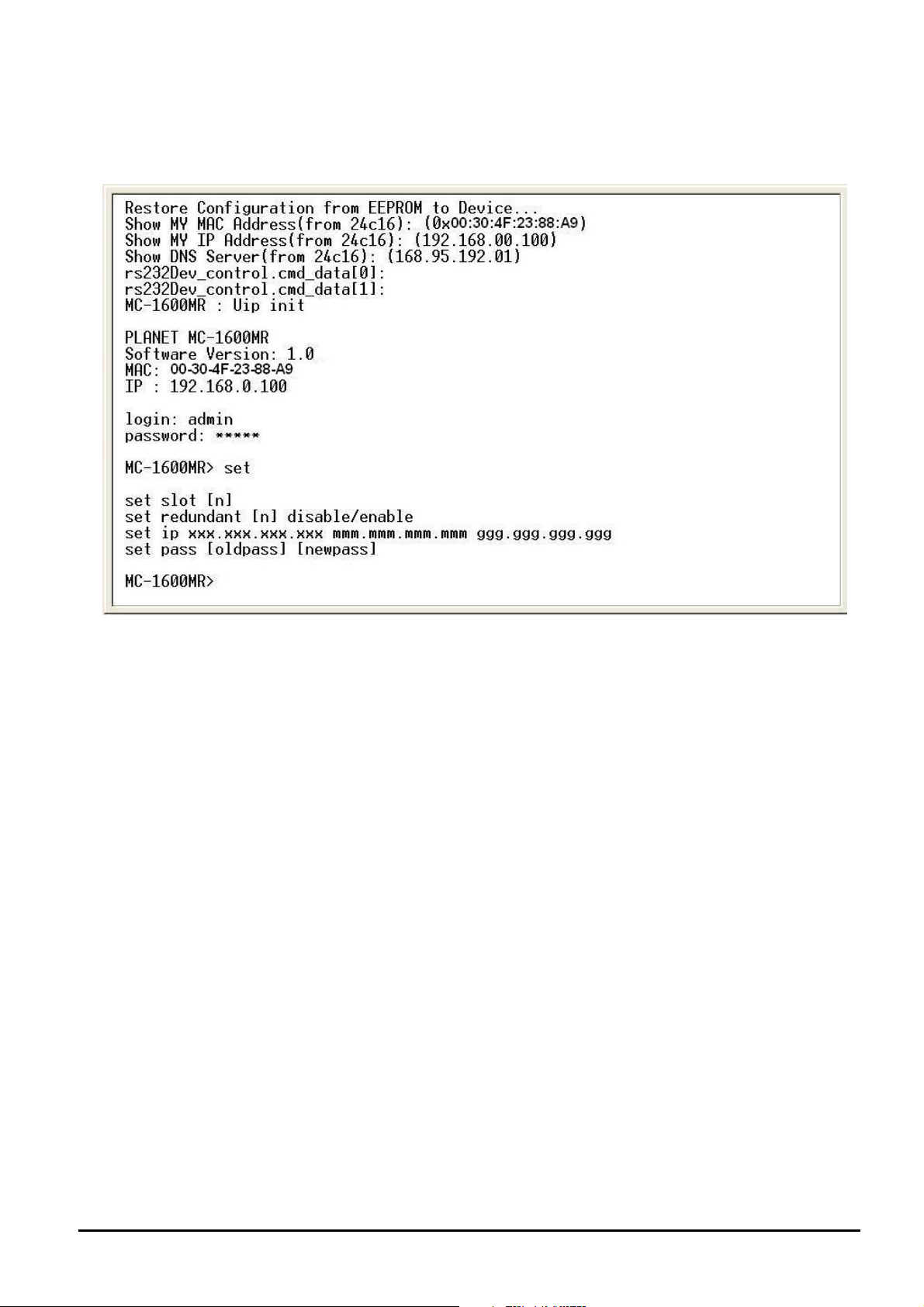
4.4.3 Set command
From the main menu screen (see Figure 4-3), input “set” and press enter. The set command list screen in Figure 4-13
appears.
This set command list contains four items:
Set slot [n]: Please refer to chapter 4.4.3.1.
Set redundant [n] disable / enable: Please refer to chapter 4.4.3.2.
Set ip xxx.xxx.xxx.xxx.mmm.mmm.mmm.mmm.ggg.ggg.ggg.ggg: Please refer to chapter 4.4.3.3
Set pass [oldpass] [newpass]: Please refer to chapter 4.4.3.4
Figure 4-13 Set command list screen
- 23 -
Page 24

4.4.3.1 Set slot [n]
This command allows configuring per slot parameters of Web Smart Media Converter Chassis, different parameters provide on FST-8 / GST-7 Media Converter boards installation. The correct usage is shown as below:
Set slot [n]: n=1-16, to configuring per slot parameters of Web Smart Media Converter Chassis. The configuring per
slot parameters screen in Figure 4-14 appears and the detail description shown in table 4-2 & 4-3.
Item Description
Device To enable or disable per FST-80x Converter board.
LLCF To enable or disable the LLCF function from FST-80x Converter board.
TP AN Mode To set the UTP port runs at Auto-negotiation or Forced Mode.
TP Speed.*
To set the UTP port runs at 100Mbps or 10Mbps.
Figure 4-14 Set slot [n] command screen
TP Duplex.*
TP FC To set the Flow Control of the UTP port to enable or disable.
Fiber LLR To enable or disable the LLR function of the Fiber port.
Fiber Duplex To set the Duplex Mode of Fiber port to Full duplex or Half duplex mode.
Item Description
Device To enable or disable per GST-70x Converter board.
Fiber LLR To enable or disable the LLR function of the fiber port.
Fiber AN Bypass To set the Auto negotiation bypass function of the fiber port to enable or disable.
To set the UTP port runs at Full duplex or Half duplex mode.
Table 4-2 Descriptions of the FST-80x slot Configuration screen Objects
Table 4-3 Descriptions of the GST-70x slot Configuration screen Objects
#Notice:
*: Only set the TP port run at force mode, the TP speed and TP duplex function are available.
- 24 -
Page 25

4.4.3.2 Set redundant [n] disable/enable
This command allows disable or enable per redundant group of Web Smart Media Converter Chassis, the correct usage is
shown as below:
Set redundant[n]disable/enable: n=1-8, to disable or enable per redundant group of Web Smart Media Converter Chassis, the screen in Figure 4-15 appears.
The redundant backup setting function already divides 8 redundant groups and each group includes 2 ports, the ports with
an odd number will be “Master”. Vice versa, the ports with even number will be Slave”.
Once enable the redundant backup setting function, only the Master fiber interface will work as a major fiber connection
and the Slave fiber interface as a backup fiber connection. When the system detects Master fiber interface disconnects
then the slave fiber interface will active as major fiber connection to avoid network downtime.
When the system detect the Master fiber interface of get recovery, then the Slave Fiber interface will disconnect automatically and become a backup fiber connection again.
Figure 4-15 Set redundant [n] disable / enable command screen
Group Master Slave
1 1 2
2 3 4
3 5 6
4 7 8
5 9 10
6 11 12
7 13 14
8 15 16
#Notice: LLCF must active on both Master and Slave devices. If not, then the redundant backup setting function will not
work.
- 25 -
Page 26

4.4.3.3 Set IP xxx,xxx,xxx,xxx,mmm,mmm,mmm,mmm, ggg,ggg,ggg,ggg
This command allows assign IP address, netmask and gateway of Web Smart Media Converter Chassis; the correct usage
is shown as below:
set ip 192.168.0.100 255.255.255.0 192.168.0.254 and press <Enter>
Then the following message appears under console interface:
The IP sets to 192.168.0.100
The netmask sets to 255.255.255.0
The gateway sets to 192.168.0.254
Means the IP address was changed successfully, the IP subnet address setting screen in Figure 4-16 appears.
Figure 4-16 Set IP command screen
4.4.3.4 Set pass [oldpass] [newpass]
This command allows assign password of Web Smart Media Converter Chassis, the password setting screen in Figure
4-17 appears.
Figure 4-17 Set pass command screen
#Notice:
1. For security reason, please change and memorize the new password after this first setup.
2. The maximum length is 8 characters.
- 26 -
Page 27

4.4.4 Factory default
This command allows reset the Web Smart Media Converter Chassis to factory default mode. The factory default screen in
Figure 4-18 & 4-19 appears.
Figure 4-18 Factory default screen
Figure 4-19 Factory default screen
- 27 -
Page 28
4.4.5 Reboot
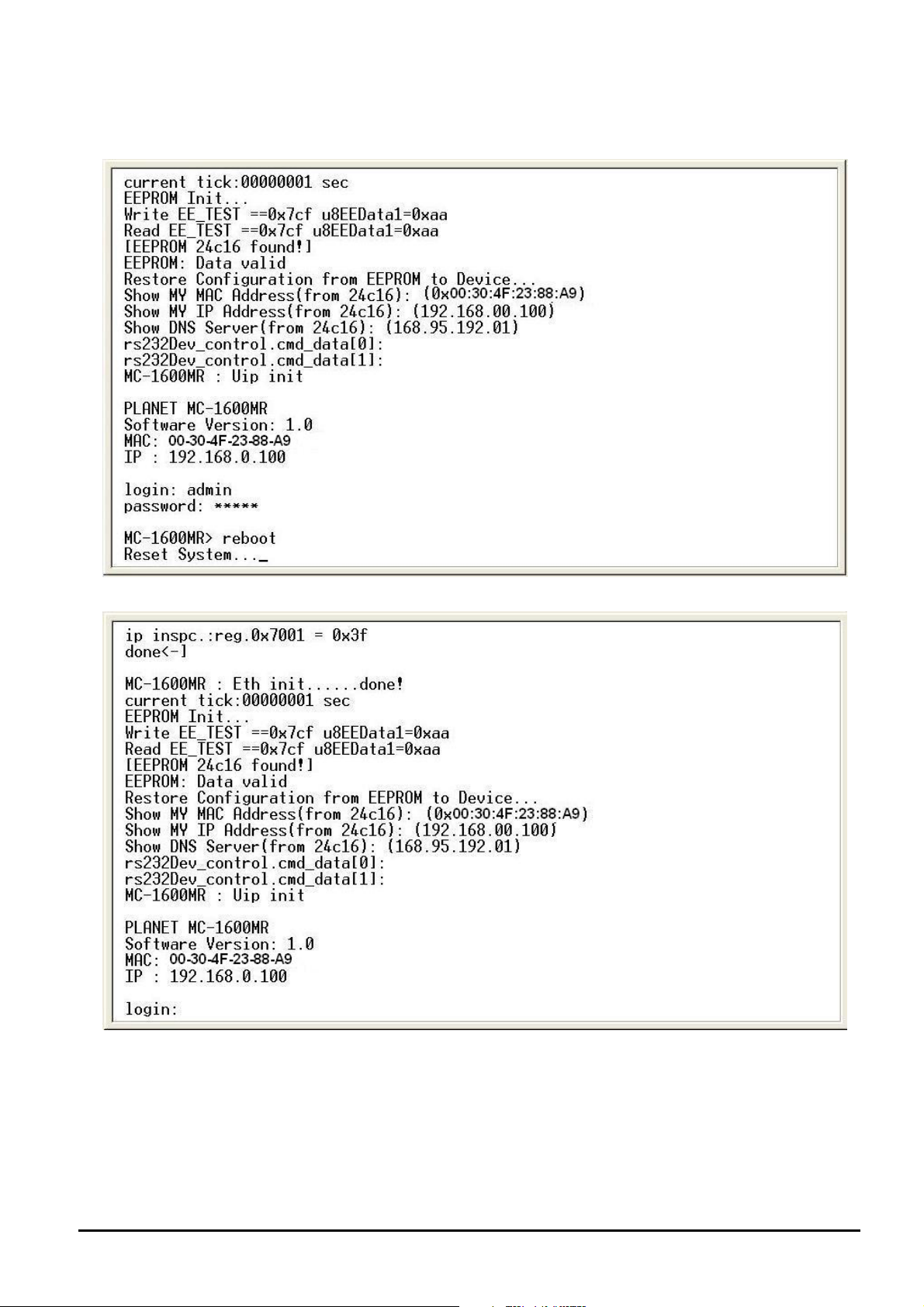
This command allows reboot the Web Smart Media Converter Chassis, the reboot screen in Figure 4-20 & 4-21 appears.
Figure 4-20 Web Smart Media Converter Chassis reboot screen
Figure 4-21 Web Smart Media Converter Chassis reboot screen
- 28 -
Page 29

4.4.6 Logout
This command provides logout the Web Smart Media Converter Chassis, the screen in Figure 4-22 appears.
Figure 4-22 Web Smart Media Converter Chassis Logout screen
- 29 -
Page 30

5. WEB MANAGEMENT
Before login the Web interface of Web Smart Media Converter Chassis, please setup the “IP Address” with local serial
console port (RS232 port) and use this IP address to configure Web Smart Media Converter Chassis through the Web
interface.
Or modify your PC’s IP domain to the same with Web Smart Media Converter Chassis then use the default IP address
(192.168.0.100) to remote configure Web Smart Media Converter Chassis through the Web interface.
5.1 Login in to the Web Smart Media Converter Chassis
To access the Web-browser interface you must first enter the user name and password, the default user name and
password is "admin". You will see the following screen comes out on the Web browser program:
Figure 5-1 The Web login Page screen of Web Smart Media Converter Chassis
After the User name and Password is entered, you will see the web main menu screen.
- 30 -
Page 31

Figure 5-2 The web main menu screen of Web Smart Media Converter Chassis
5.2 Chassis Status
This section provides current status of power supply unit from Web Smart Media Converter Chassis, the screen in Figure
5-3 appears.
Figure 5-3 Chassis Status Web Page screen
- 31 -
Page 32
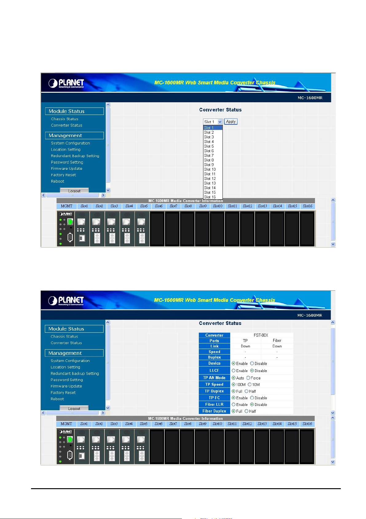
5.3 Converter Status
This section introduces detail settings of per slot parameters from Web Smart Media Converter Chassis; the screen in
Figure 5-4 appears.
Figure 5-4 Converter Status Web Page screen
Different parameters provide on FST-8 / GST-7 Media Converter boards installation, the screen in Figure 5-5 & Figure 5-6
appears and table 5-1 & 5-2 descriptions the slot configuration objects of Web Smart Media Converter Chassis.
Figure 5-5 Converter Status Web Page screen
- 32 -
Page 33

Item Description
Device To enable or disable per FST-80x Converter board.
LLCF To enable or disable the LLCF function from FST-80x Converter board.
TP AN Mode To set the UTP port runs at Auto-negotiation or Forced Mode.
TP Speed.*
TP Duplex.*
TP FC To set the Flow Control of the UTP port to enable or disable.
Fiber LLR To enable or disable the LLR function of the Fiber port.
Fiber Duplex To set the Duplex Mode of Fiber port to Full duplex or Half duplex mode.
Table 5-1 Descriptions of the FST-80x slot Configuration screen Objects
To set the UTP port runs at 100Mbps or 10Mbps.
To set the UTP port runs at Full duplex or Half duplex mode.
#Notice:
*: Only set the TP port run at force mode, the TP speed and TP duplex function are available.
Figure 5-6 Converter Status Web Page screen
Item Description
Device To enable or disable per GST-70x Converter board.
Fiber LLR To enable or disable the LLR function of the Fiber port.
Fiber AN Bypass
- 33 -
To set the Auto negotiation bypass function of the Fiber port to enable or disable.
Table 5-2 Descriptions of the GST-70x slot Configuration screen Objects
Page 34

5.4 System Configuration
This section introduces detail parameters of Web Smart Media Converter Chassis, such as IP subnet address setting and
firmware version and Mac address display. The screen in Figure 5-7 appears and table 5-3 descriptions the System
Configuration objects of Web Smart Media Converter Chassis.
Figure 5-7 System Configuration Web Page screen
Item Description
IP Address Allow to input new IP address of Web Smart Media Converter Chassis.
Subnet Mask Allow to input new Subnet Mask address of Web Smart Media Converter Chassis.
Default Gateway
Firmware Version
MAC Address
Submit
Cancel
Allow to input new default Gateway of Web Smart Media Converter Chassis.
Display current firmware version of Web Smart Media Converter Chassis.
Display MAC Address of Web Smart Media Converter Chassis.
Save the current configuration of Web Smart Media Converter Chassis.
Ignore current configuration of Web Smart Media Converter Chassis.
Table 5-3 Descriptions of the System Configuration screen Objects
- 34 -
Page 35

Once, change the IP subnet address and click the “Submit” button to take effect. The Web Smart Media Converter
Chassis will proceed following procedure and ask re-login with new IP address. The screen in Figure 5-8 & 5-9 & 5-10 &
5-11 appears.
Figure 5-8 System Configuration Web Page screen
Figure 5-9 System Configuration Web Page screen
- 35 -
Page 36

Figure 5-10 System Configuration Web Page screen
Figure 5-11 System Configuration Web Page screen
- 36 -
Page 37
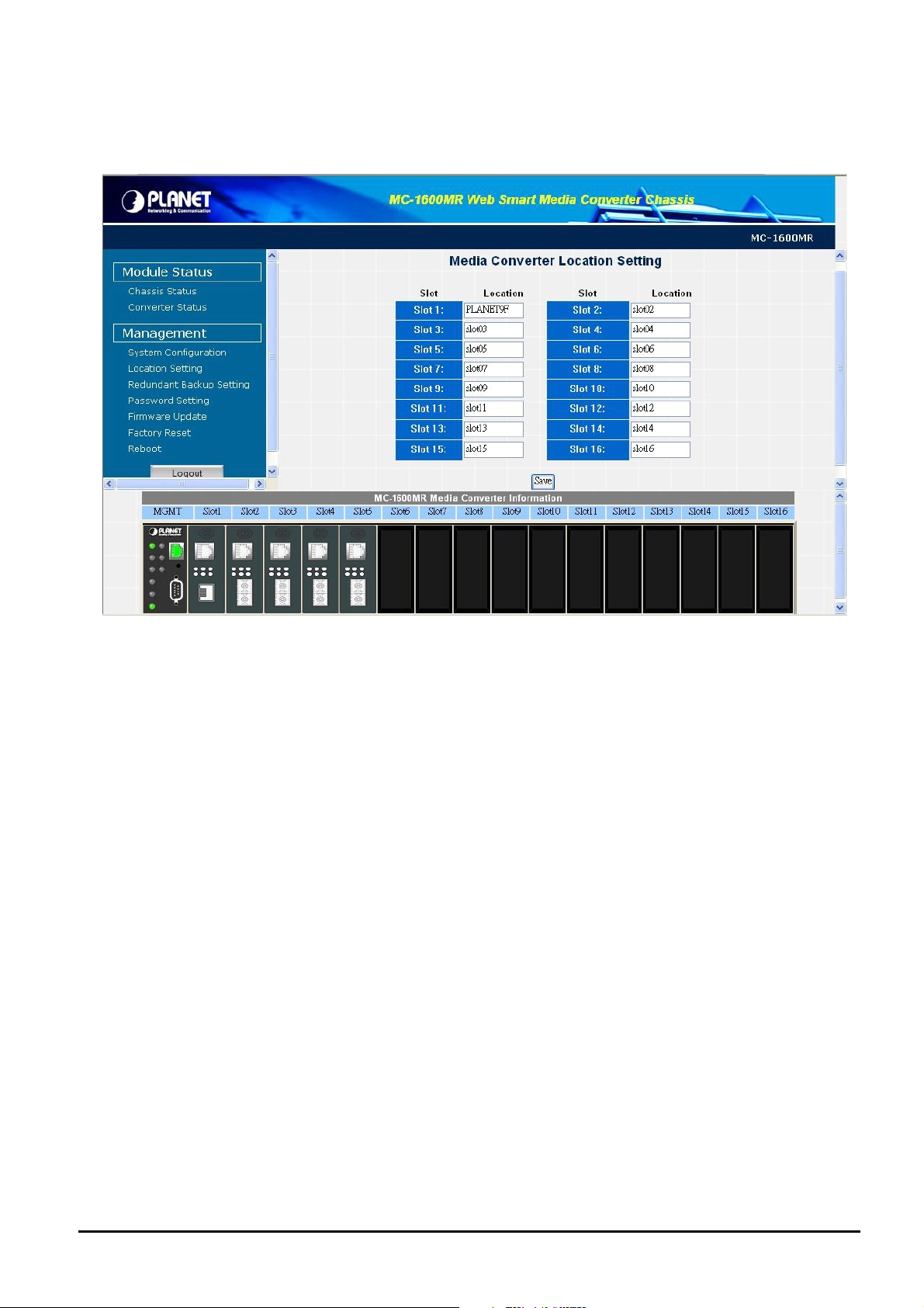
5.5 Location Setting
This section allows you to add location description on each slot of Web Smart Media Converter Chassis, the screen in
Figure 5-12 appears.
Figure 5-12 Location Setting Web Page screen
After setup completed, press “Save” button to save current configuration.
#
Notice: The maximum length is 8 characters.
- 37 -
Page 38

5.6 Redundant Backup Setting
This section allows you to enable or disable redundant backup setting function of Web Smart Media Converter Chassis, the
screen in Figure 5-13 appears.
Figure 5-13 Redundant Backup Setting Web Page screen
The redundant backup setting function already divides 8 redundant groups and each group includes 2 ports, the ports with
an odd number will be “Master”. Vice versa, the ports with even number will be Slave”.
Once enable the redundant backup setting function, only the Master fiber interface will work as a major fiber connection
and the Slave fiber interface as a backup fiber connection. When the system detects Master fiber interface disconnects
then the slave fiber interface will active as major fiber connection to avoid network downtime.
When the system detect the Master fiber interface of get recovery, then the Slave Fiber interface will disconnect automatically and become a backup fiber connection again.
#
Notice: LLCF must active on both Master and Slave devices. If not, then the redundant backup setting function will not
work.
- 38 -
Page 39
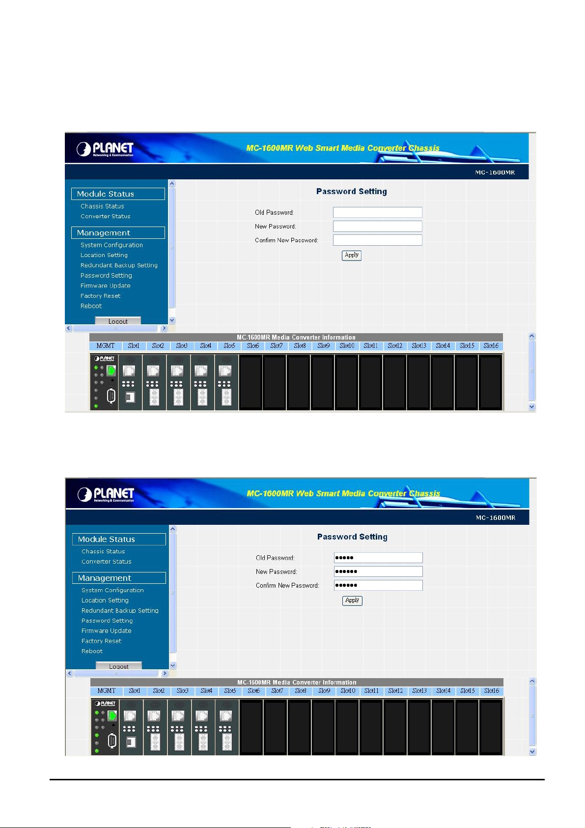
5.7 Password Setting
This section allows you to create a new password for Web Smart Media Converter Chassis, the screen in Figure 5-14
appears.
Figure 5-14 Password Setting Web Page screen
Please input the current password in “Old Password” space, then input new password twice in space of “New Pass-
word” and “Confirm New Password”. The screen in Figure 5-15 appears.
- 39 -
Page 40
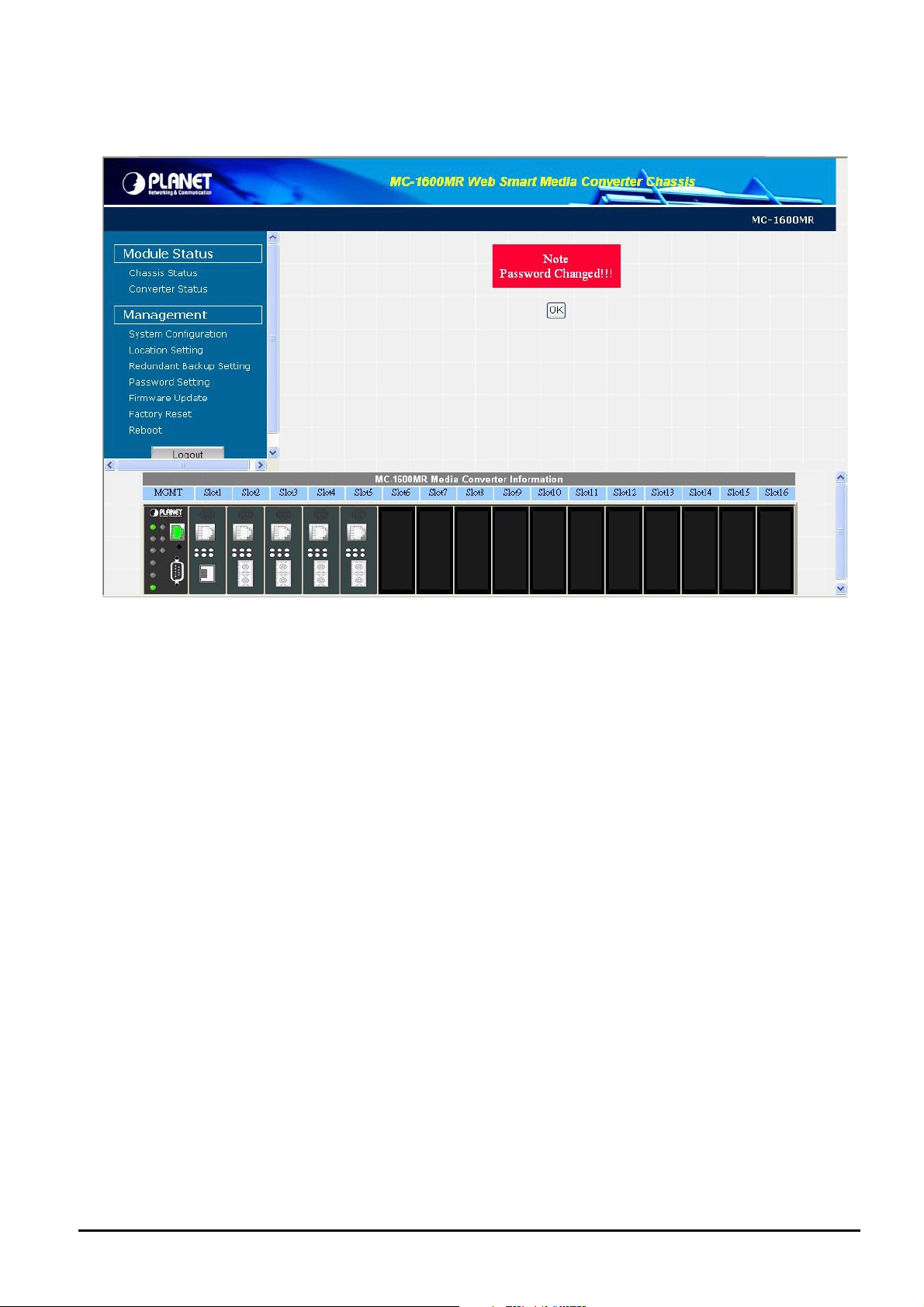
Figure 5-15 Password Setting Web Page screen
Press “Apply” button to save current configuration, the following screen in Figure 5-16 appears.
Figure 5-16 Password Setting Web Page screen
Please use the new password to login the Web Smart Media Converter Chassis on next login.
#
Notice:
1. For security reason, please change and memorize the new password after this setup.
3. The maximum length is 8 characters.
- 40 -
Page 41
5.8 Firmware Upgrade
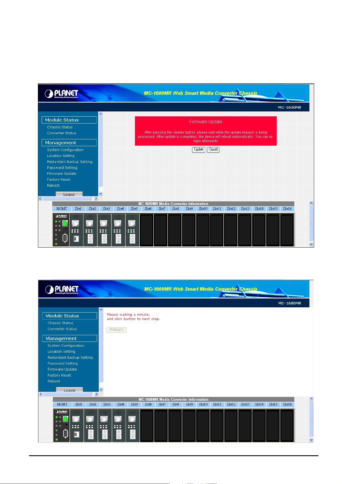
This section provides firmware upgrade of Web Smart Media Converter Chassis, after choose this function and the fol-
lowing screen appears in Figure 5-17. Please press “Update” button to continue following firmware upgrade process.
Figure 5-17 Firmware upgrade Web Page screen
Please wait for two seconds and press “Continue” to next firmware upgrade web page, the screen in Figure 5-18 appears.
- 41 -
Page 42

Figure 5-18 Firmware upgrade Web Page screen
Please press “Browser” to locate the latest firmware of Web Smart Media Converter Chassis that deposit in your PC and
press “Upgrade” to start the firmware upgrade process. The screen in Figure 5-19 appears.
Figure 5-19 Firmware upgrade Web Page screen
Please wait for twenty-four seconds and go to next firmware upgrade web page, the screen in Figure 5-20 appears.
- 42 -
Page 43

Figure 5-20 Firmware upgrade Web Page screen
Then the re-login screen appears in Figure 5-21, please press “Re Login” button to re-login web interface of Web Smart
Media Converter Chassis with latest firmware version, the screen in Figure 5-22 appears.
Figure 5-21 Firmware upgrade Web Page screen
Figure 5-22 The Web Smart Media Converter Chassis login Web Page screen
- 43 -
Page 44
#Notice: Please does not power off the Web Smart Media Converter Chassis during firmware upgrade process.
5.9 Restore System Default
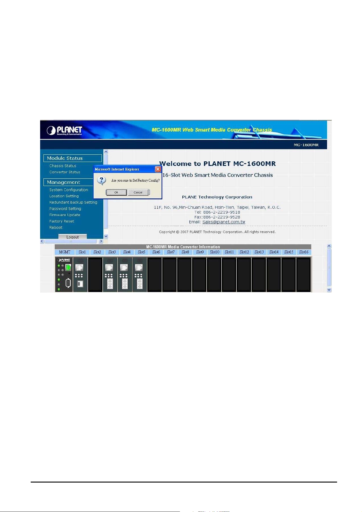
This section provides reset the Web Smart Media Converter Chassis to factory default mode, after choose this function and
the following screen appears in Figure 5-23. Please press “OK” button to take effect and the Web Smart Media Converter
will reboot automatically, please refresh current Web page or create a new Web page from Internet browser. Please
re-login the web interface with default username and password “admin”, the screen in Figure 5-24 appears.
Figure 5-23 Reset to factory default Web Page screen
- 44 -
Page 45

Figure 5-24 Web Smart Media Converter Chassis login Web Page screen
5.10 Reboot System
This section provides reboot the Web Smart Media Converter Chassis, after choose this function and the following screen
appears in Figure 5-25. Please press “OK” button to take effect and the Web Smart Media Converter will reboot auto-
matically, please refresh current Web page or create a new Web page from Internet browser. Please re-login the web
interface with default username and password “admin”, the screen in Figure 5-26 appears.
Figure 5-25 Reboot Web Page screen
- 45 -
Page 46
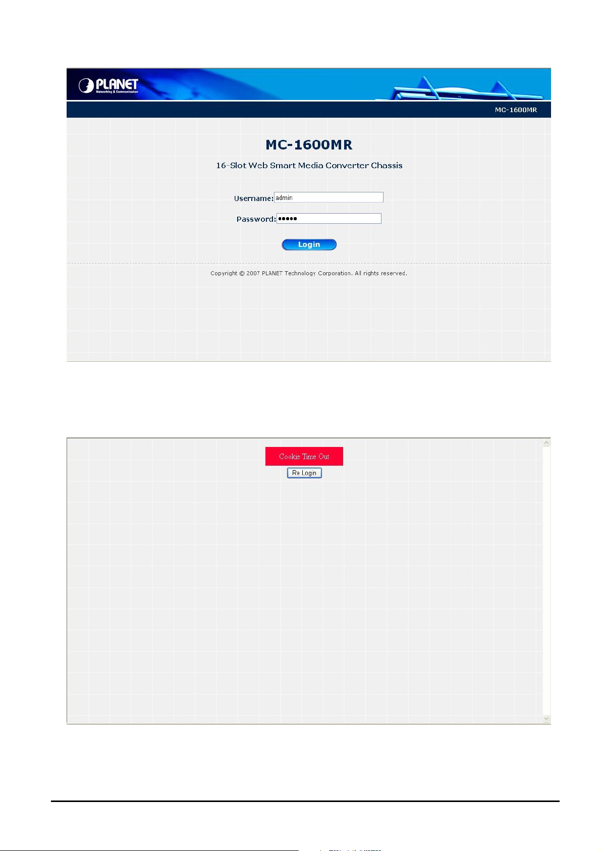
Figure 5-26 Web Smart Media Converter Chassis login Web Page screen
5.11 Logout
This section allows to logout the Web Smart Media Converter Chassis, the screen in Figure 5-27 & 5-28 appears.
Figure 5-27 Web Smart Media Converter Chassis Logout Web Page screen
- 46 -
Page 47
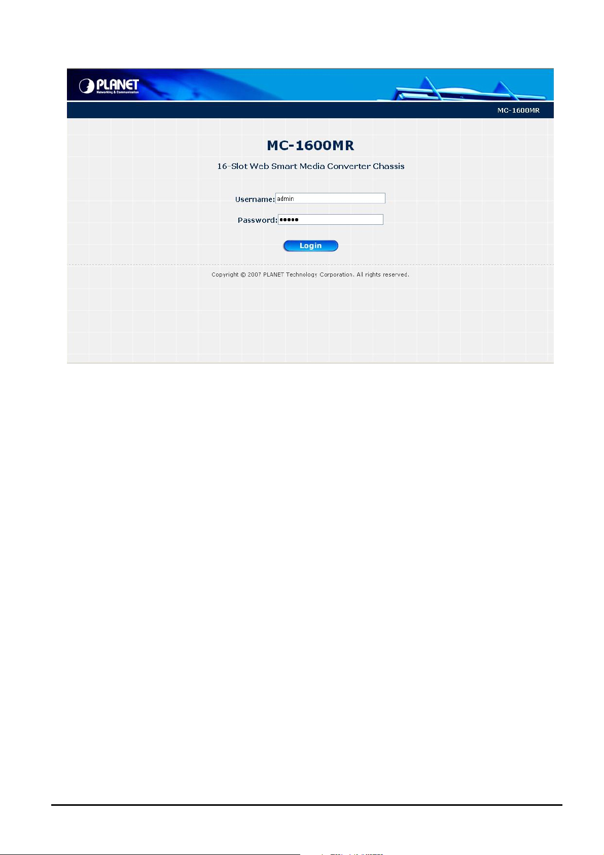
Figure 5-28 Web Smart Media Converter Chassis login Web Page screen
- 47 -
Page 48
6. LINK PASS THROUGH FUNCTION
The LFP function includes the Link Fault Pass Through function (LLCF/LLR). LLCF/LLR can immediately alarm adminis-
trators the problem of the link media and provide efficient solution to monitor the net.
LLCF (Link Loss Carry Forward) means when a device connected to the converter and the TP line loss the link, the
converter’s fiber will disconnect the link of transmit. LLR (Link Loss Return) means when a device connected to the con-
verter and the fiber line loss the link, the converter’s fiber will disconnect the link of transmit. Both can immediately alarm
administrators the problem of the link media and provide efficient solution to monitor the net.
6.1 Link Loss Carry Forward (LLCF)
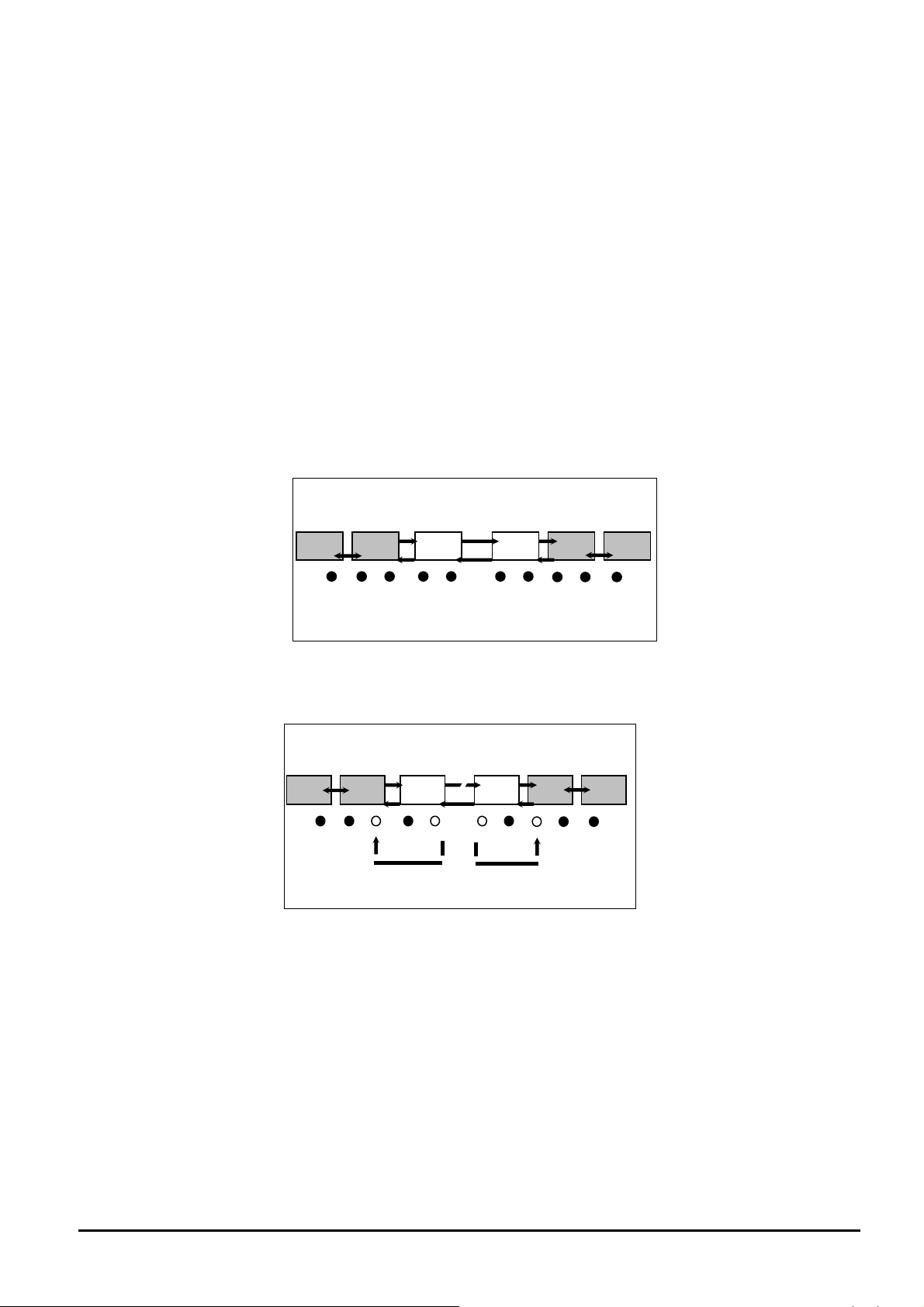
The LLCF function for troubleshooting a remote connection. When LLCF is enabled, the FL/TP ports do not transmit a link
signal until they receive a link signal from the opposite port.
The diagram below shows a typical network configuration with a good link status using FST-8/GST-7 Media Converter
boards for remote connectivity.
Management Switch/Hub Media Media Switch/Hub Management
Station w/SNMP Converter Converter w/SNMP Station
LLCF is ON
TP
Fiber
LLCF is ON
TP
● LED lit = established link ○ LED unlit = no link
If the connection breaks, FST-8/GST-7 Media Converter boards that link loss forward to the switch/hub which generates a
trap to the management station. The administrator can then determine the source of the issue.
Management Switch/Hub Media Media Switch/Hub Management
Station w/SNMP Converter Converter w/SNMP Station
● LED lit = established link ○ LED unlit = no link
LLCF is ON
TP
Broken
Fiber
LLCF is ON
TP
- 48 -
Page 49

6.2 Link Loss Return (LLR)
The LLR function for troubleshooting a remote connection. LLR works in conjunction with LLCF.
When LLR is enabled, the port’s transmitter shuts down when its receiver fails to detect a valid receive link. LLR should only
be enabled on one end of the link and is typically enabled on either the unmanaged or remote device.
The diagram below shows a typical network configuration with a good link status using FST-8/GST-7 Media Converter
boards for remote connectivity.
Note that LLR and LLCF are enabled as indicated in the diagram.
Ma nage ment Swit ch/ Hub M edia Med ia Swit ch/H ub M anag eme nt
Station w/SNMP Converter Converter w/SNMP Station
LLCF is ON
Fiber
Cable
● LED lit = established link ○ LED unlit = no link
If one of the optical conductors is bad (as shown in the diagram box below), the converter with LLR enabled will return a
no-link condition to its link partner. With LLCF also enabled, the no-link condition is carried forward to the switch/hub where
a trap is generated to the management station, and the administrator can then determine the source of the loss.
LLCF is ON
Management Switch/Hub Media Media Switch/Hub Management
Statio n w/SNMP Co nverter Con verter w/SNMP Station
● LED lit = established link ○ LED unlit = no link
Link Loss Carried Forward Link Loss Carried Forward
LLCF is ON
Broken
Port 2
Link Loss Returned
LLCF is ON
Port 1
- 49 -
Page 50

7. TROUBLESHOOTING
This chapter contains information to help you solve issues. If the Web Smart Media Converter Chassis is not functioning
properly, make sure the device was set up according to instructions in this manual.
The Power LED is not lit
Solution:
Check the power cable connection between power supply unit and Web Smart Media Converter Chassis.
What is the difference between MC-7/10/15 series chassis and MC-1600M series chassis?
Solution:
Except provide power supply to each slot and centralize management, the MC-1600M series chassis
also provide local command line console and remote Web interface for efficient management.
Can I install FT-70x/FT-80x and GT-70x series Media converter into the Web Smart Media Converter
Chassis?
Solution:
No. due to different hardware designed, the FT-70x / FT-80x and GT-70x cannot install into Web Smart Media
Converter Chassis.
What if I forget current password of Web Smart Media Converter Chassis?
Solution:
1. Please enter into console interface, use username: planet and password: [^_^] to access
console interface. Then use “show pass” command to display current password.
2. Please press “Reset” button from the management module for 5 seconds then the Web Smart
Media Converter Chassis will reset to factory default mode (username and password is admin).
- 50 -
Page 51

APPENDIX A NETWORKING CONNECTION
A.1 Switch‘s RJ-45 Pin Assignments
10/100Mbps, 10/100Base-TX
RJ-45 Connector pin assignment
Contact MDI
MDI-X
Media Dependant
Interface
1 Tx + (transmit) Rx + (receive)
2 Tx - (transmit) Rx - (receive)
3 Rx + (receive) Tx + (transmit)
4, 5 Not used
6 Rx - (receive) Tx - (transmit)
7, 8 Not used
Media Dependant
Interface -Cross
A.2 RJ-45 cable pin assignment
The standard RJ-45 receptacle/connector
There are 8 wires on a standard UTP/STP cable and each wire is color-coded. The following shows the pin allocation
and color of straight cable and crossover cable connection:
Figure A-1: Straight-Through and Crossover Cable
Please make sure your connected cables are with same pin assignment and color as above picture before deploying the
cables into your network.
2080-AA3450-000
- 51 -
 Loading...