

Page 1

PLANET Mesh Network Manager Guide
Page 1 of 126
802.11a/b/g Indoor/Outdoor Wireless Mesh
Network Access Point
MAP-3100 / MAP-3120 / MAP-3020
Mesh Network Man ager (MnM)
Management Uti lity User Manual
PLANET Mesh Network Manager Guide
Page 2

PLANET Mesh Network Manager Guide
Page 2 of 126
Copyright
Copyright 2009 by PLANET Technology Corp. All rights reserved. No part of this publication may
be reproduced, transmitted, transcribed, stored in a retrieval system, or translated into any language
or computer language, in any form or by any means, electronic, mechanical, magnetic, optical,
chemical, manual or otherwise, without the prior written permission of PLANET.
PLANET makes no representations or warranties, either expressed or implied, with respect to the
contents hereof and specifically disclaims any warranties, merchantability or fitness for any particular
purpose. Any software described in this manual is sold or licensed "as is". Should the programs prove
defective following their purchase, the buyer (and not PLANET, its distributor, or its dealer) assumes
the entire cost of all necessary servicing, repair, and any incidental or consequential damages
resulting from any defect in the software. Further, PLANET reserves the right to revise this publication
and to make changes from time to time in the contents hereof without obligation to notify any person
of such revision or changes.
All brand and product names mentioned in this manual are trademarks and/or registered trademarks
of their respective holders.
Revision
Mesh Network Manager User’s Manual for PLANET Wireless Mesh Access Point
Model: MAP-3020 / MAP-3120/MAP-3100
Rev: 4.0 (July, 2009)
Part No. EM-MAP3K_MnMv4.doc
PLANET Mesh Network Manager Guide
Page 3

PLANET Mesh Network Manager Guide
Page 3 of 126
Table of Content
Table of Content 3
1 Overview 6
2 System Requirement 7
3 Utility Installation and Un-installation 8
3.1 Installation 8
3.1.1 Introduction 9
3.1.2 Choose Install Folder 9
3.1.3 Choose Shortcut Folder 10
3.1.4 Pre-Installation Summary 11
3.1.5 Installing 12
3.1.6 Installation Complete 13
3.2 Un-installation 13
3.2.1 Introduction 14
3.2.2 Uninstalling 14
3.2.3 Uninstallation Complete 15
4 How to Use PLANET Mesh Network Management Tools 16
4.1 Quick Start 16
4.2 Software Overview & Features 17
4.2.1 Software Layout 17
4.2.1.1 Map Container 17
4.2.1.2 MIB Reader 18
4.2.1.3 Alarm Viewer 19
4.2.2 Toolbar Reference 20
4.2.3 Features 22
4.2.3.1 Create Map 22
4.2.3.2 Open Map 23
4.2.3.3 Save Map 23
4.2.3.4 Topology Map 24
4.2.3.5 Set up New Scan 25
4.2.3.6 Map View 26
4.2.3.7 Status Pane 27
4.2.3.8 Scan IP Address 28
4.2.3.9 SNMP Community / Passwords (for Scan-IP) 28
4.2.3.10 Socket Port 30
4.2.3.11 SNMP Community / Passwords (for AP Unit) 30
4.2.3.12 Scan Interval 31
4.2.3.13 Import Background Image 32
4.2.3.14 Map Print 33
4.2.3.15 Map Zoom 34
4.2.3.16 Customize Map 35
4.2.3.17 Background Image Tra nspar e ncy 38
4.2.3.18 Block List 39
4.2.3.19 Lock / Unlock 40
4.2.3.20 Node details 41
PLANET Mesh Network Manager Guide
Page 4

PLANET Mesh Network Manager Guide
Page 4 of 126
4.2.3.21 Client Properties 42
4.2.3.22 Get/Set using MIB Reader 43
4.2.3.23 Load/Unload MIB 46
4.2.3.24 Alarm Table 47
4.2.3.25 Add Trap Agent 48
4.2.3.26 View Log Files 50
4.2.3.27 Show Route 51
4.2.3.28 Create VPN Connection 53
4.2.3.29 Configure Mesh APs 58
4.2.3.30 Discovery Tool 60
4.2.3.31 View Interface and Client Live Statistic 60
4.2.3.32 Logout Client 62
5 Configure the Mesh AP using AP Configurator 64
5.1 Overview of AP Configurator 64
5.2 How to use AP Configurator 65
5.3 Configure the Mesh AP 67
5.3.1 System > system 67
5.3.1.1 System > Syslog 69
5.3.1.2 System > Advanced Tuning 69
5.3.1.3 Network > Network 72
5.3.1.4 Network > WAN (MAP-3100 only) 73
5.3.1.5 Network > VLAN 77
5.3.1.6 Network > Mesh 79
5.3.1.7 Network > Wireless Configuration 82
5.3.1.8 Network > Route 85
5.3.1.9 Network > IP Sec (MAP-3100 only) 86
5.3.1.10 Network > L2TP Client 88
5.3.1.11 Network > OLSR (MAP-3100 only) 89
5.3.1.12 Services > NTP 91
5.3.2 Services > DHCP (MAP-3100 only) 93
5.3.2.1 Services > MAC Access 95
5.3.2.2 Services > NAT (MAP-3100 only) 97
5.3.2.3 Services > Firewall (MAP-3100 only) 98
5.3.2.4 Services > Traffic Shaping (MAP-3100 only) 100
5.3.2.5 Services > PPTP Server (MAP-3100 only) 102
5.3.2.6 Services > Mobile IP (Future Feature) (MAP-
3100 only) 104
5.3.2.7 Services > Captive Portal 105
5.3.2.8 Services > Radius 107
5.3.2.9 Services > Dynamic DNS 109
5.3.2.10 Services > Zero Config (MAP-3100 only) 110
5.3.2.11 Services > Auto IP (MAP-3100 only) 110
5.3.2.12 Services -> Route Watch Dog (MAP-3100 only)
5.3.2.13 Services -> System Watch Dog (MAP-3100
only) 112
5.3.2.14 Services -> SSHD 112
5.3.2.15 Services > WME 113
5.3.2.16 Management > HTTPD 115
111
PLANET Mesh Network Manager Guide
Page 5

PLANET Mesh Network Manager Guide
Page 5 of 126
5.3.2.17 Management > SNMPD 117
5.3.2.18 Management > SNMP Trap 119
5.3.2.19 Management > NMS Address 122
5.3.2.20 Status > DHCP Client 123
5.3.2.21 Command > Reboot 123
5.3.2.22 Command > Reset 124
5.3.2.23 Command > Download/Upload 124
6 Technical Support 126
PLANET Mesh Network Manager Guide
Page 6

PLANET Mesh Network Manager Guide
Page 6 of 126
1 Overview
This document provides a details information and application guidance for the user of the
management software, the PLANET Mesh Network Manager (MnM). This network
management s ystem is intended to perf orm an overa ll m onitoring and conf igur ing features for
the PLANET Mesh Network.
PLANET Mesh Network Manager Guide
Page 7

PLANET Mesh Network Manager Guide
Page 7 of 126
2 System Requirem ent
The PLANET Mesh Network Manager is written in JAVA, hence it has the feature of cross
platform, capable to run in most of the platform. The following are the recommended system
requirement.
- 256 MB RAM (recommended minimum)
- 10 MB hard disk space
- Microsoft Windows 2000, XP (recommended)
Besides, in order to enable the NMS to work properly, the following ports must be allowed
through any firewall between the NMS and the agent:
- Port 161 (by default) – Use for standard SNMP Get and Set
- Port 162 (by default) – Use for listen to SNMP Trap
- Port 4608 (by default) – Used by the Discovery Tool
- Port 8188 (by default) – Use to listen for the Layer-2 node’s notification
PLANET Mesh Network Manager Guide
Page 8
PLANET Mesh Network Manager Guide
Page 8 of 126
3 Utility Installation and Un-installation
3.1 Installation
Insert the bundled CD into the CD-ROM drive to launch the auto run program. Once
completed, a menu s creen will appear. Click the “PLANET Mesh Netw ork Manager v_2.8.7”
hyperlink and select “Open” or “Run” to initiate the install wizard.
After the wizard completes preparation, follow the 6 easy steps directed by the wizard to
perform the installation.
PLANET Mesh Network Manager Guide
Page 9
PLANET Mesh Network Manager Guide
Page 9 of 126
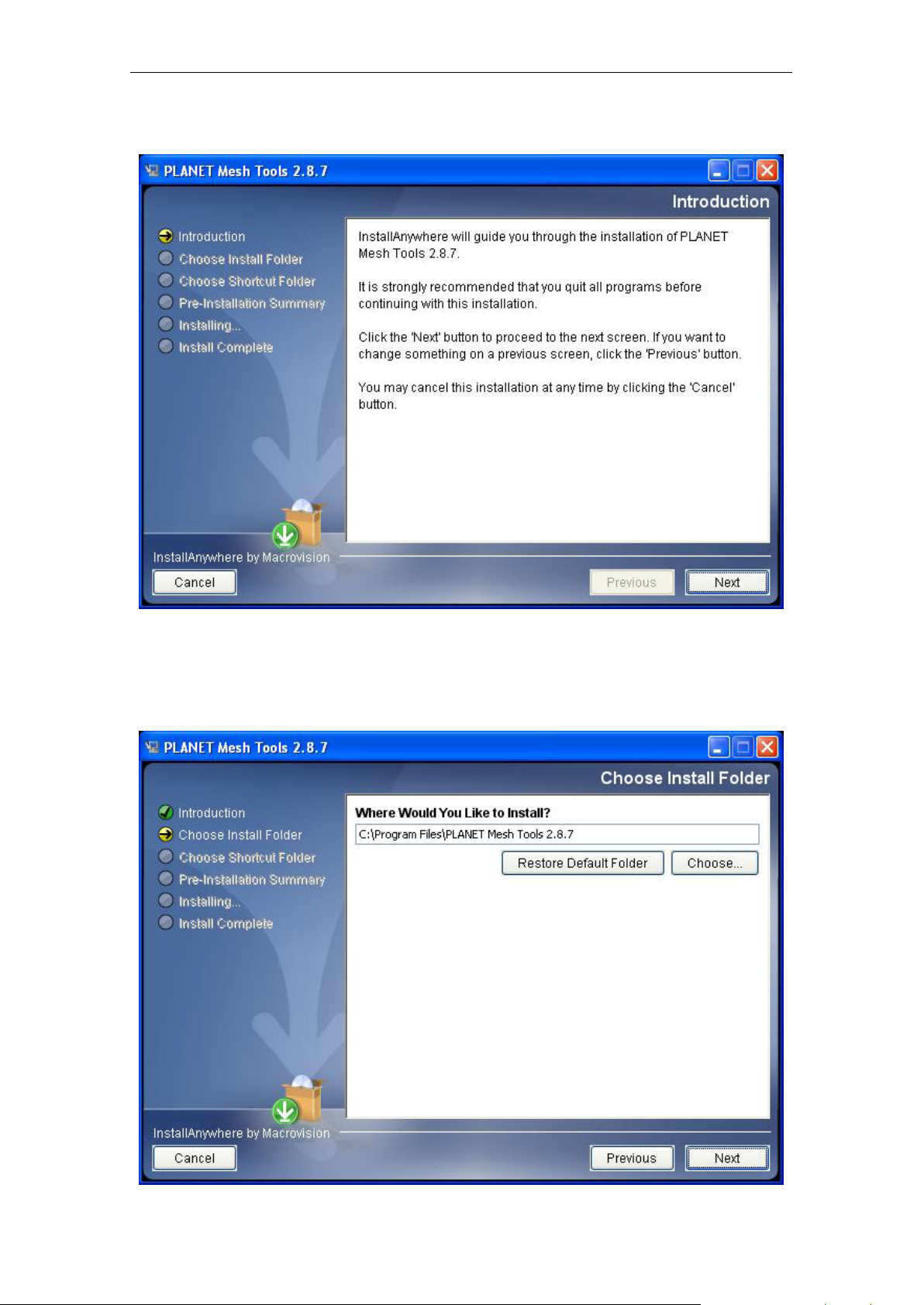
3.1.1 Introduction
Simply explain what this software is about. Press Next to proceed.
3.1.2 Choose Install Folder
PLANET Mesh Network Manager Guide
Page 10
PLANET Mesh Network Manager Guide
Page 10 of 126
Prompt user to choose t he install path (directory) and name the install folder. Press Next to
proceed.
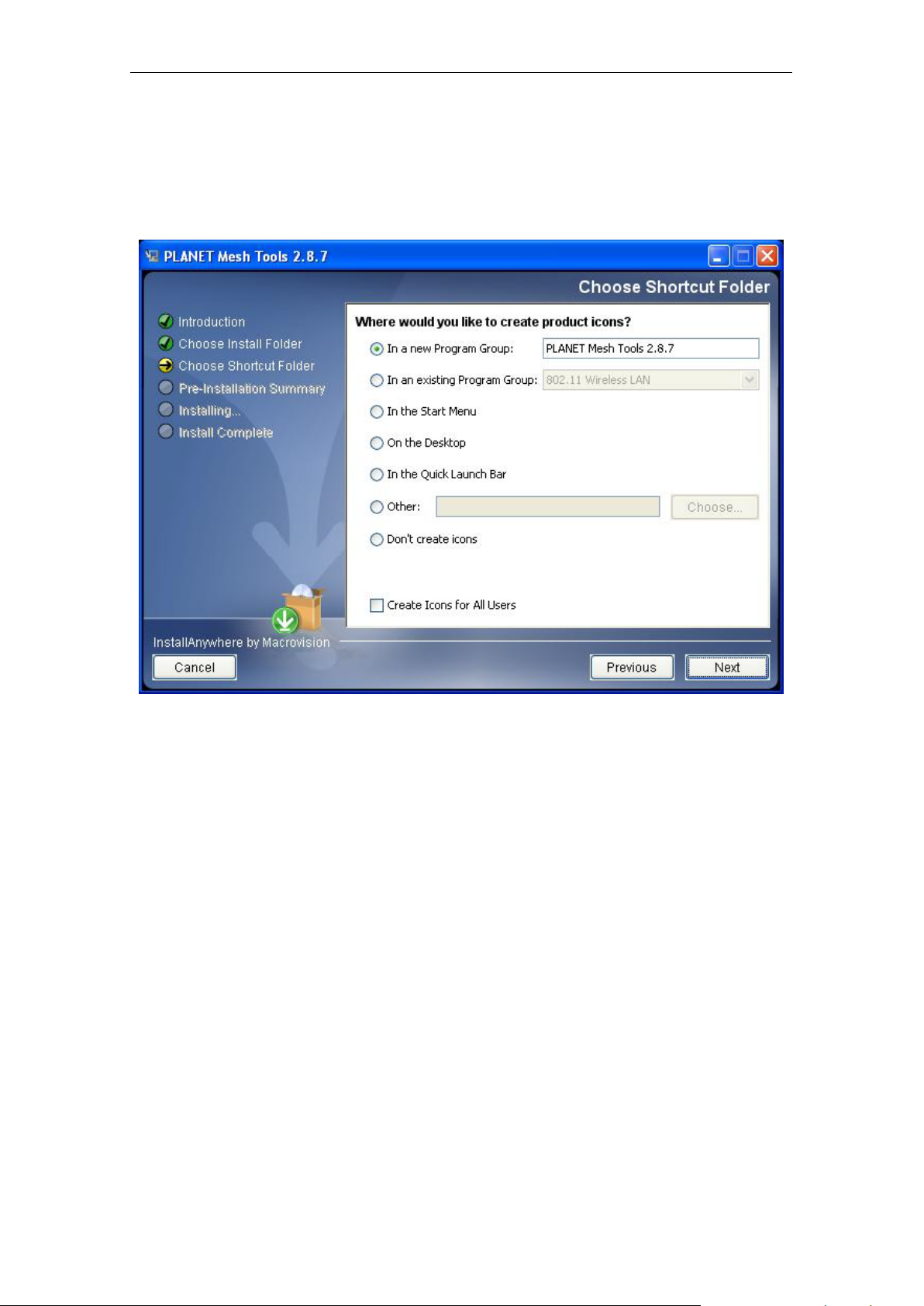
3.1.3 Choose Shortcut Folder
Specify where the software shortcut will be created at. Press Next to proceed.
PLANET Mesh Network Manager Guide
Page 11
PLANET Mesh Network Manager Guide
Page 11 of 126
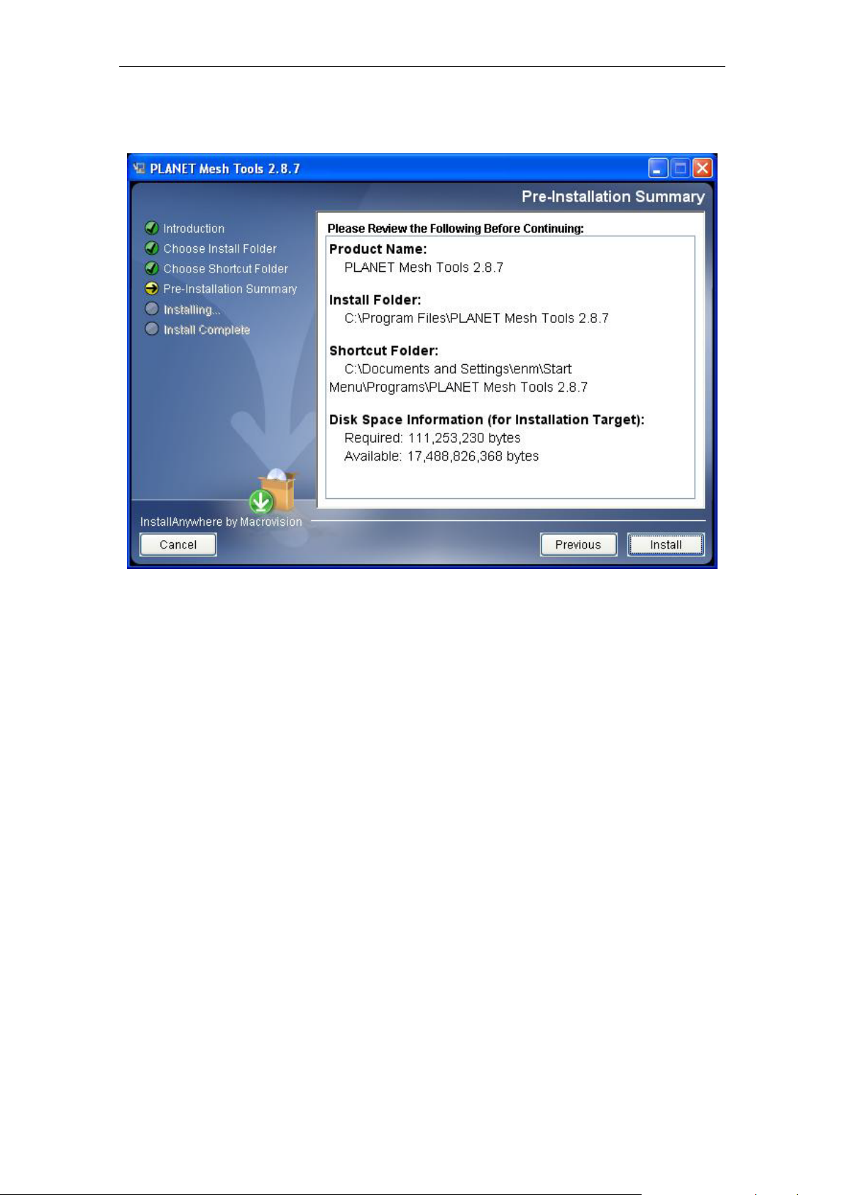
3.1.4 Pre-Installation Summary
Let user have a quick review about the installation settings before start installing. Press
Install button to start the installation.
PLANET Mesh Network Manager Guide
Page 12
PLANET Mesh Network Manager Guide
Page 12 of 126
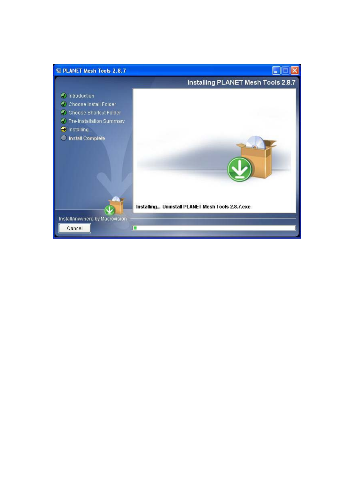
3.1.5 Installing
Installation is in progress. Once the installation is com pleted it will direc t the user to the nex t
step.
PLANET Mesh Network Manager Guide
Page 13
PLANET Mesh Network Manager Guide
Page 13 of 126
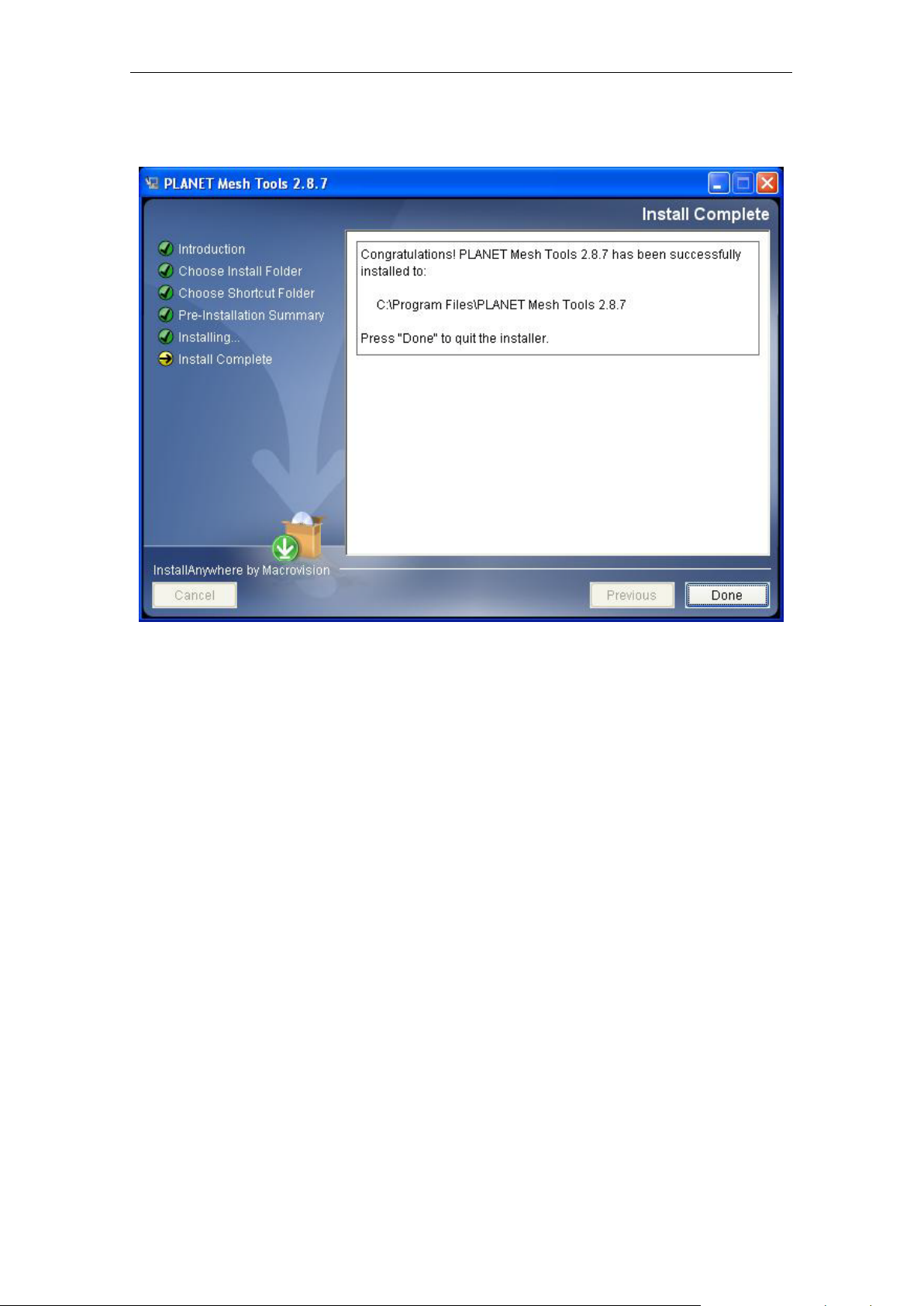
3.1.6 Installation Complete
Indicating the installat ion is completed, and user can s elect to restart the s ystem instantly or
afterward, in order to complete the installation. Press Done to conclude the ins tal lat ion. After
that, you may launch the NMS through the shortcut you created previously.
3.2 Un-installation
In order to unins tall the PL ANET Mesh Net work Manager f rom your terminal , you can get the
uninstaller wizard from the software directory. The uninstaller, namely Uninstall PLANET
Mesh Tools, is located at the U ninstall_PLANET Mesh Tools folder. Launch the uninstaller
wizard by double-click the executable file. Follows the following steps:
PLANET Mesh Network Manager Guide
Page 14
PLANET Mesh Network Manager Guide
Page 14 of 126
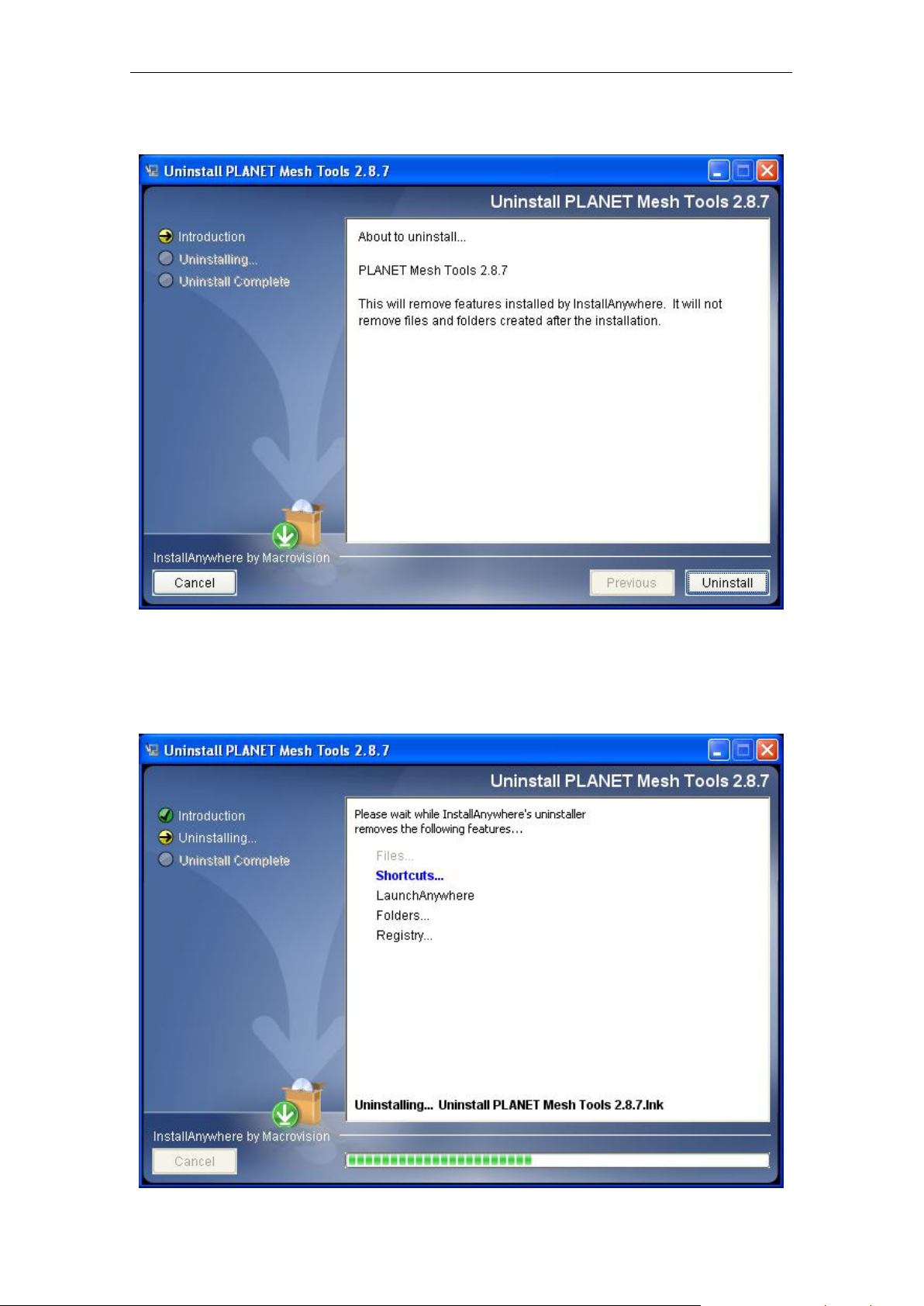
3.2.1 Introduction
An introduction regarding the uninstallation of the PLANET Mesh Management Tool. Click
Uninstall to start the process.
3.2.2 Uninstalling
PLANET Mesh Network Manager Guide
Page 15
PLANET Mesh Network Manager Guide
Page 15 of 126
Uninstallation is in the pro gress. Once the progr ess is completed, it will aut omatically direct
you to the next step.
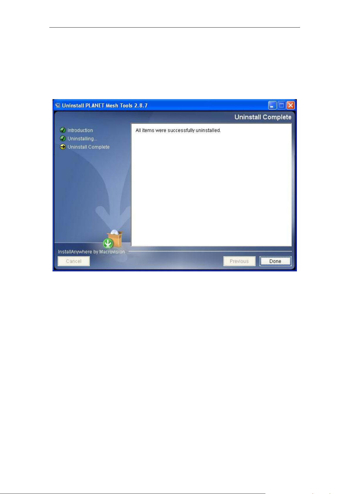
3.2.3 Uninstallation Complete
The software is uninstalled. You may choose to restart the term inal instantly or afterward in
order to complete the process.
PLANET Mesh Network Manager Guide
Page 16

PLANET Mesh Network Manager Guide
Page 16 of 126
4 How to Use PLANET Mesh Network
Management Tools
4.1 Quick Start
First of all, make sure the terminal where you installed your PLANET Mesh Network
Management Tools is connected to the network, via W ireles s or Wired LAN. Then, launch th e
NMS at the location where you install it.
For a Layer 3 Mesh network:
Click the Creat e Map butto n on t h e too lb ar t o ge nerat e a ne w map profile. A dialog box would
appear, select SNMP Map and enter the name of th e ne w pr of ile . After th at, hit t h e OK button
to complete the set up. A new map will be inserted into the NMS.
Then, click on the drop-do wn list on the toolbar of th e new profile, where it prom pts users to
insert the Scan IP Address, the d estination IP Address to be scanned. Enter the desired IP
and click the button next t o the list to save the I P. Finally, select the Start Scan button on the
map’s toolbar, the scan will be initiated and run . The result of the scan w ill be plotted on the
map area. User is free to adjust the position of the found-unit on the map.
For a Layer 2 Mesh network:
Prior to set up the utilit y, u ser is required to add the IP address of the NMS terminal on the
web page (Management > NMS Addresses) of Layer 2 nodes.
After the Layer 2 node configuration is done, activate the NMS and click the Create Map
button. A dialog box would appear, select Layer-2 M ap and enter the name of the new profile.
After that, hit the OK button to complete the setup. A new map will be inserted into the NMS.
Before shutting do wn the NMS, us er can s ave the profile settings , includi ng the c oordinat e of
the found Mesh AP units on the map, by click on the Save Map button on the m ap toolbar.
The saved profile can be lo aded dir ectl y to the NMS next time using the Op en Map butto n on
the toolbar.
For further description regarding the functions and features of the PLANET Mesh Network
Management Tools, user may refer to the following section.
PLANET Mesh Network Manager Guide
Page 17
PLANET Mesh Network Manager Guide
Page 17 of 126
4.2 Software Overview & Features
4.2.1 Software Layout
Before we procee d further, let us have an overview at the layout of the NMS. Basically, the
PLANET Mesh Network Management Tools is consists of three major sections:
Map Container
MIB Reader
Alarm Viewer
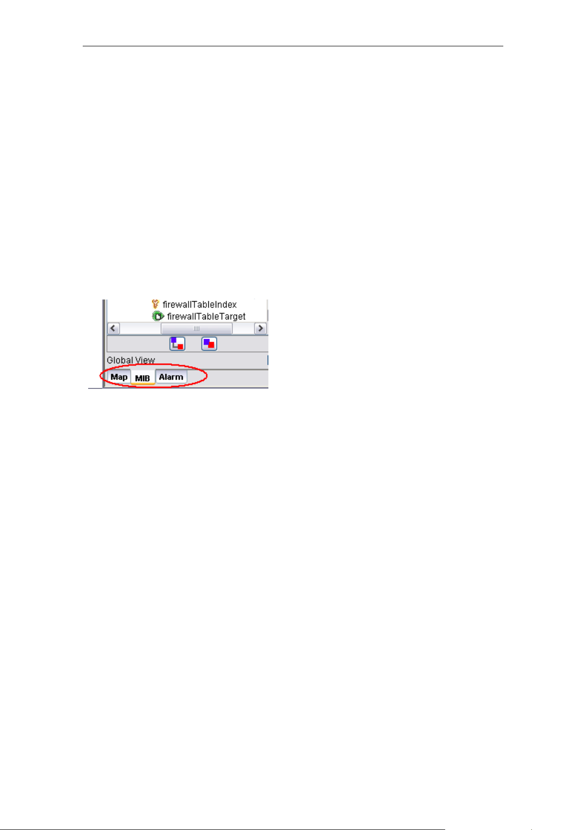
User can switch t he vie w of the NMS by sel ec t th e tab s at t he left bo ttom corner, as illustrated,
or through the menu bar.
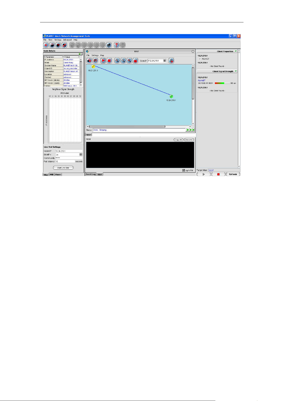
4.2.1.1 Map Contai ner
The Map Container is the section where user can monitor an d manage the mesh network.
The network will be disp layed in the form of graphical topolog y map, and the status will be
updated periodically.
The center frame of the Map Container is the space t o plot the topolo gy map. More tha n one
map can be created and run simultaneously. The status of the map will be logged to the
status pane at the bottom of the map. Each topology map has its own status pane.
The panel at the left of the map space is the Node Details panel. It is used to display the
properties of the s elected Mesh A P unit on the topolog y map. The inform ation of the AP will
be loaded into the table, an d the gr aph bel o w th e table sho ws the s i gna l st rengt h between the
selected AP with its neighbour APs. The column at th e bottom of this panel is used to invok e
the live stat monitoring feature.
The right panel, m eanwhile, is to dis play the details of the c lients associated to t he Mesh AP
unit. The panel is divided into two parts, the Client Properties and Client Signal Strength
portion. Each portion will be autom atically updated every minute, to provide the admin user
the live result regarding the clients.
PLANET Mesh Network Manager Guide
Page 18
PLANET Mesh Network Manager Guide
Page 18 of 126
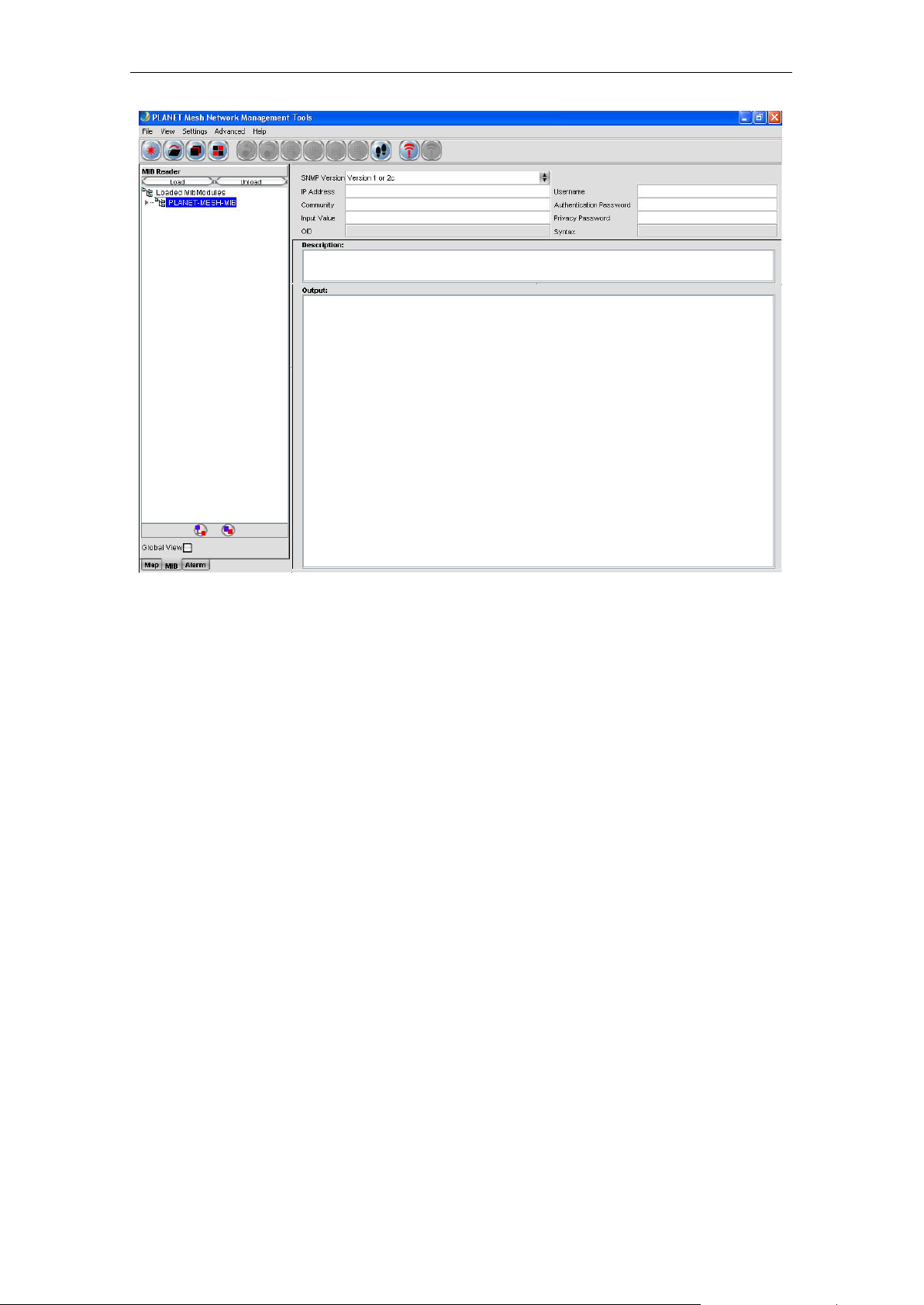
4.2.1.2 MIB Reader
The MIB Reader provides user a sim ple user-interface to retrieve as well as configure the
settings of the Mesh AP unit through t he standard or vendor proprietary MIB files. W ith the
correct community and password, user can perform the SNMP actions such a s SNMPGet,
SNMPSet and SNMPTable.
PLANET Mesh Network Manager Guide
Page 19
PLANET Mesh Network Manager Guide
Page 19 of 126
The left pane displa ys the lis t of MIB and its tr ee. Use r can lo ad and unload M IB f ile from the
desired location. More th an one f ile can b e lo ade d in to the MIB Reader. In order to read or set
an item, expand the MIB tree, selec t the desired node . Select the SNM P version; fill in the IP
Address and other necessary keyword. Then click on the command button (SnmpGet,
SnmpSet, SnmpWalk, Load Table, etc..) on the toolbar. T he output will be shown on the
Output column.
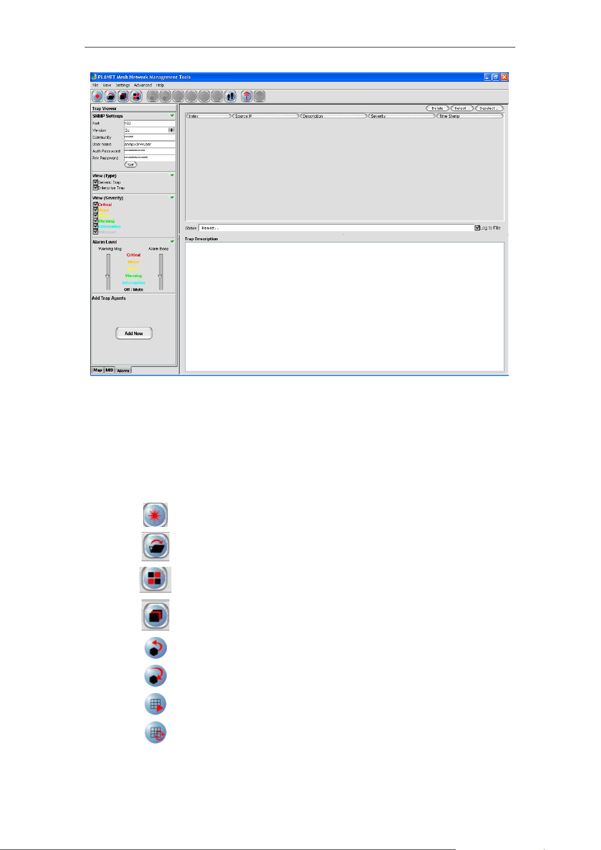
4.2.1.3 Alarm Viewer
The Alarm Viewer is a trap receiver. It received the SNMP alarms and notifications directed by
the Mesh AP units and display in the table at the center frame. Select the table e ntry in order
to view the description of the trap.
Note that the table is a read-only table, which displays the trap’s source IP Address,
description, severity and the time when the trap or alarm was caught. These alarms should be
deleted once they were reviewed and resolved, by clicking the Delete button.
PLANET Mesh Network Manager Guide
Page 20
PLANET Mesh Network Manager Guide
Page 20 of 126
Button
Name
Function
Create Map
Open Map
View Tile
View the topology map in grid layout
View Cascade
View the topology map in cascade layout
SnmpGet
SnmpGet the data from MIB tree
SnmpSet
Load Table
Load the SNMP table from MIB tree
Refresh Table
Refresh the SNMP table from MIB tree
4.2.2 Tool ba r Reference
This section provides a quick reference for the buttons in the toolbar of the NMS. The
description of the toolbar of the NMS is illustrated at the table below:
Create a new topology map profile
Open a pre-saved topology map profile
SnmpSet the data from MIB tree
PLANET Mesh Network Manager Guide
Page 21
PLANET Mesh Network Manager Guide
Page 21 of 126
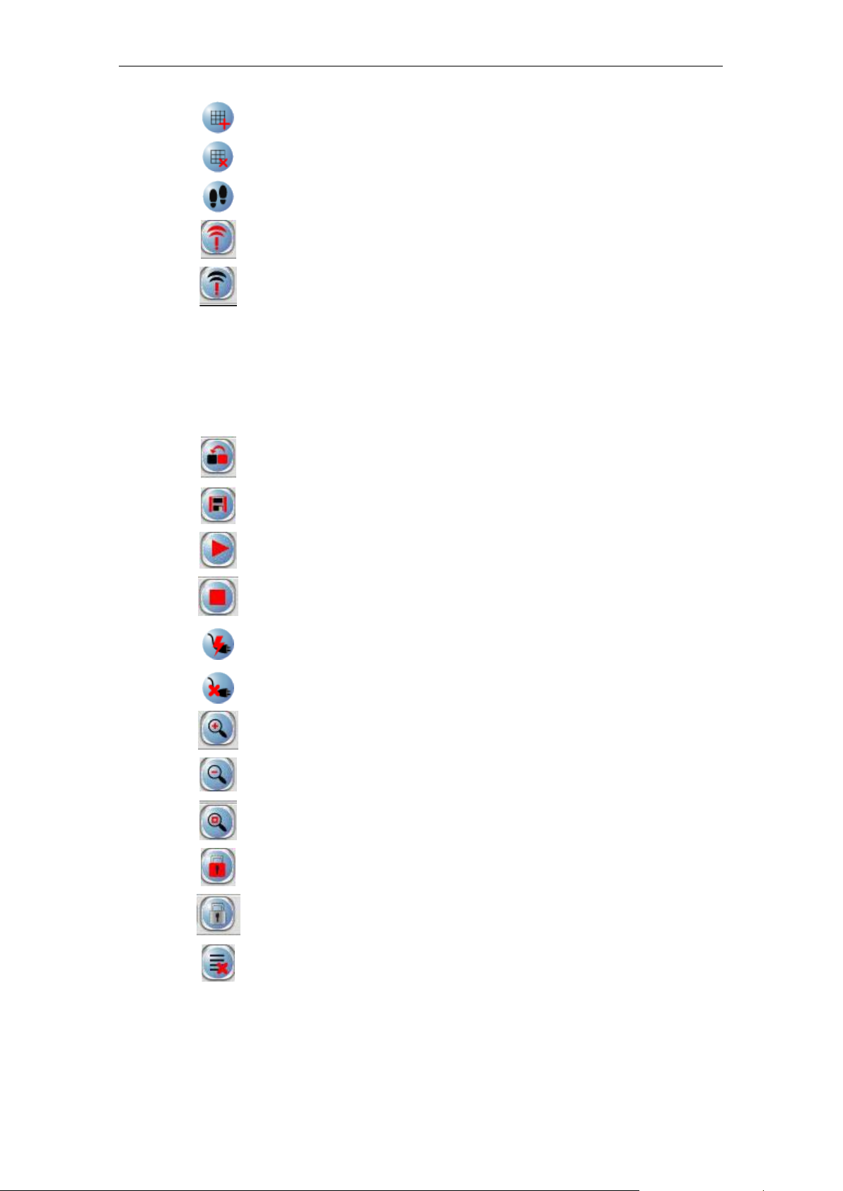
Add Table Row
Add a row to SNMP Table
Del Table Row
Delete a row from SNMP Table
SnmpWalk
Walk the selected item from the MIB tree
Start Trap
Initiate the Alarm Host system
Stop Trap
Stop the Alarm Host system
Button
Name
Function
Import
Save Profile
Save the current topology map
Scan Start
Start the network scanning (SNMP Map only)
Scan Stop
Initiate Port
Open port to listen to La yer-2 notification ( Layer-2
Close Port
Close Layer-2 notification port (Layer-2 Map only)
Zoom In
Zoom in the topology map by 25%
Zoom Out
Zoom out the topology map by 25%
Zoom Fit
Zoom the topology map to a size that fit the
Lock
Lock the AP units on the map
Unlock
Unlock the AP units on the map
Block List
Open the block list window
On the other hand, the following table shows the description of the toolbar of the map
container:
Import an image file to use as the background
Background
image of the topology map
Stop the network scanning (SNMP Map only)
Map only)
screen
PLANET Mesh Network Manager Guide
Page 22
PLANET Mesh Network Manager Guide
Page 22 of 126
4.2.3 Features
4.2.3.1 Create Map
In the NMS, two to polog y m aps are availa ble: SNMP Map and La yer-2 Map. T hes e two types
of map look similar. The main difference between them is the method to get the topology
information.
• The SNMP Map is the ordinary t ype, where it uses the SNMP protoco l to collect the
topology from the nodes di sc overed, and then plot the map using the collaborat e data.
• Whereas the Layer-2 M ap opens a specific port to listen for the notif ication from the
nodes, in order to p lot the map. Prior to this, us er is r equ ir ed to
the NMS terminal (IP Address) to the no de. Thus in fact, the Layer-2 Map can recei ve
the notification not only from the layer-2 m ode AP, but any other m ode as well, as
long as the NMS Address table is set.
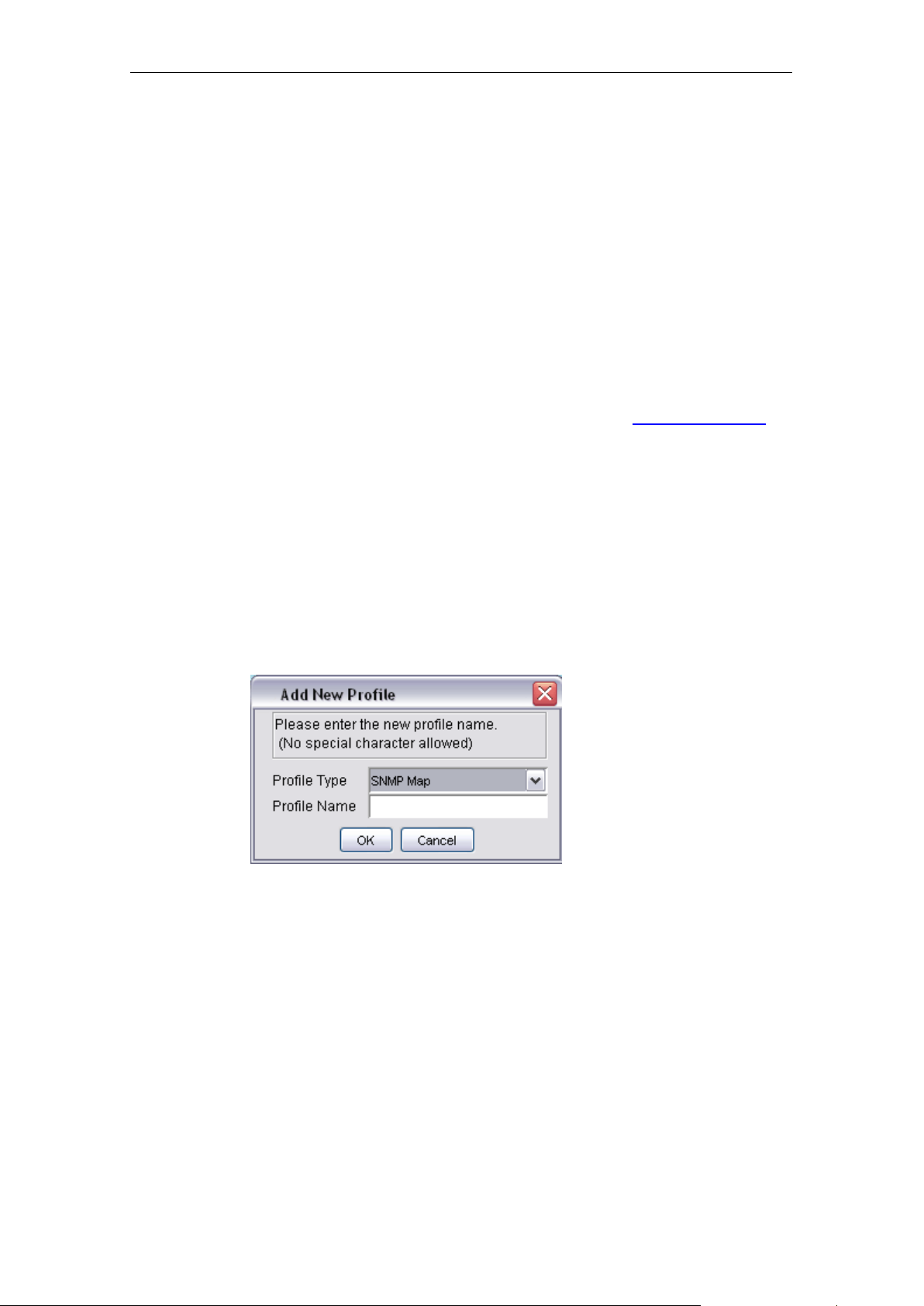
In order to create a new Topology map profile, user can click on the Create New button on
the main toolbar, or select File > Create Ne w from the menu bar. A window would turn out to
prompt user for the type and name of the new map. User may select the t ype of the profile
from the drop down list, and enter the name in the provided column.
add the inform at ion of
Please be aware that spec ial character s uch as #, $, % (exc ept _), are not allow ed to use as
the name of the topolo gy map name to a void data corrupti on, since the n ame of the m ap will
be used as the header of their data f ile. On the other hand, the system also not allow user to
create a new profile with the name of the existing map in the NMS.
Two Profile Types can be found, SNMP Map and Layer 2 Map . Please chose SNMP Map for
Layer 3 mode Mesh Network Management and Layer 2 Map for Layer 2 Mode Mesh Network
Management.
Hit the OK button to proceed, or Cancel to close the window.
PLANET Mesh Network Manager Guide
Page 23
PLANET Mesh Network Manager Guide
Page 23 of 126
guide section 3.5.10 for more.
Please make sure your Layer 2 Mesh Nodes are pre-configured for this MnM
installed PC. Otherwise, MnM can not display your Mesh nodes in the map also
Note
cannot show the correct information at the mean time. Please also refer to Web
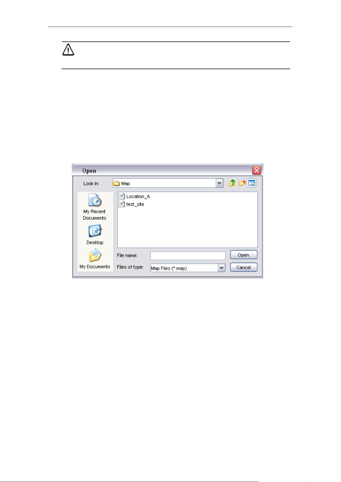
4.2.3.2 Open Map
In stead of create a br and new topo log y map, user ca n re-open the map pr ofile t hat has been
saved previousl y. Click the Open M ap button, or select File > Open Map from menu bar, a
file chooser window would appear on t he screen, to prom pt user to choos e a map. Select t he
desired one, and hit the Open button. The profile will be loaded to the NMS with all its
settings.
4.2.3.3 Save Map
As mentioned previously, the settings of the map profile can be saved to be loaded in the
future. Details of the m ap, for instance, the coordinate and SNMP passwords of the Mesh AP
units on the map, background image and block list, will be saved as a setting file.
In order to save a profile, select the Save Map button or File > Save Map from the map
container toolbar of that particular m ap profile you wish to save. N ote that if user is trying to
save a map profile tha t has a same nam e as one of the existin g profile, a warning m essage
would appear to get confirmation from the user to overwrite the file. To proceed with the action,
click the OK button.
PLANET Mesh Network Manager Guide
Page 24
PLANET Mesh Network Manager Guide
Page 24 of 126
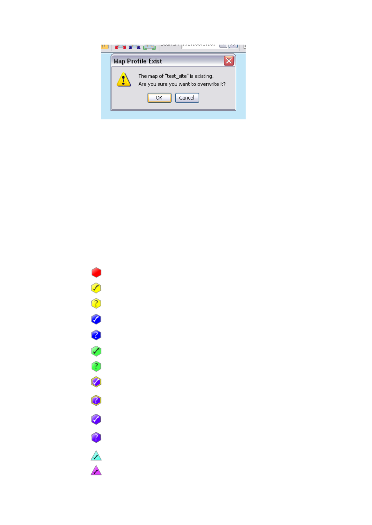
Icon
Indication
Layer-2 AP, which did not notify the NMS (disc overed as
By default, the profile will be s aved t o the Map folder in the progr am’s directory, with the name
of the map profile and ex te ns ion .map or .l2map.
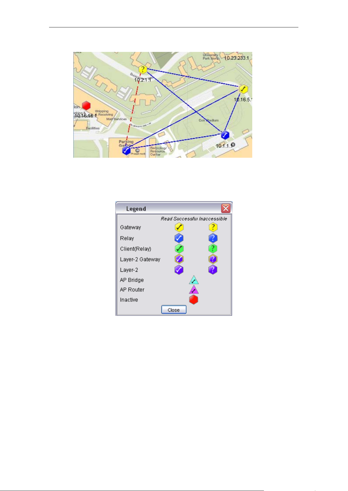
4.2.3.4 Topology Map
The topology map is actually the graphical representation of the actual Mesh network
topology which is bein g scanned. W hen a new scan is initiat ed, the result of the scan will be
processed by the NMS, and output to the map.
The AP unit would appear in different colors:-
Inactive AP
Accessible gateway AP
Inaccessible gateway AP
Accessible relay AP
Inaccessible relay AP
Accessible client-relay AP
Inaccessible client-relay AP
Layer-2 gateway AP, which notified the NMS
Layer-2 gateway AP, which did not notify the NMS
(discovered as neighbour)
Layer-2 AP, which notified the NMS
neighbour)
AP Bridge
AP Router
PLANET Mesh Network Manager Guide
Page 25
PLANET Mesh Network Manager Guide
Page 25 of 126
The blue line in between the APs designates the solid link; whereas the red, dashed line
shows th e indirect link . On the other hand, user may hit the Help > Legend opt ion from the
menu bar to view the legend regarding the topology.
4.2.3.5 Set up New Scan
In order to set up a new scan for a SNMP topology map, c lick on the Start Scan button, or
select Map > Start Scan from the menu b ar. Conversely, hit the Stop Scan button or se lect
Map > Stop Scan to halt the scanning process. The status of the map will be updated
periodically, hence whenever there is a change in t he network, us er might be a ble to m onitor
via the NMS. The status bar at the bottom of the map displays the status of the scan.
On the other hand, in order to set up a new scan f or the Layer-2 topology map, c lick on the
Initiate Port button, or select Map > Initiate Port from the menu bar. The map will receive the
notification sent by the AP and plot th e topology on the map. Convers ely, hit the Close Po rt
button or select Map > Close Port from the menu bar to stop listen to the notification.
PLANET Mesh Network Manager Guide
Page 26
PLANET Mesh Network Manager Guide
Page 26 of 126
Every new found Mesh AP unit will be place on the right top angle on the map, with zero
coordinate. Then user is f ree to move the AP unit around the m ap. Once user com pletes the
positioning, save th e map, and the system wil l remember the new coordi nates in the future
scan.
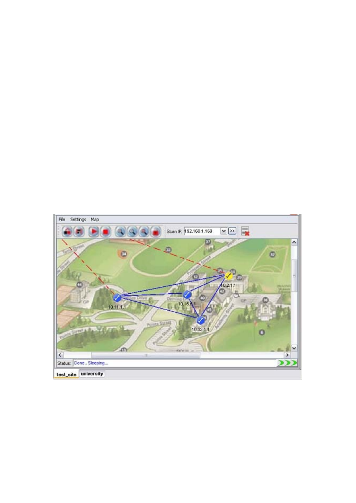
4.2.3.6 Map View
More than one topology map can be loaded to the NMS at the same time. By default, the
maps are viewed in cascade m ode, where user needs to click on the tab at the bottom to
switch the map to view.
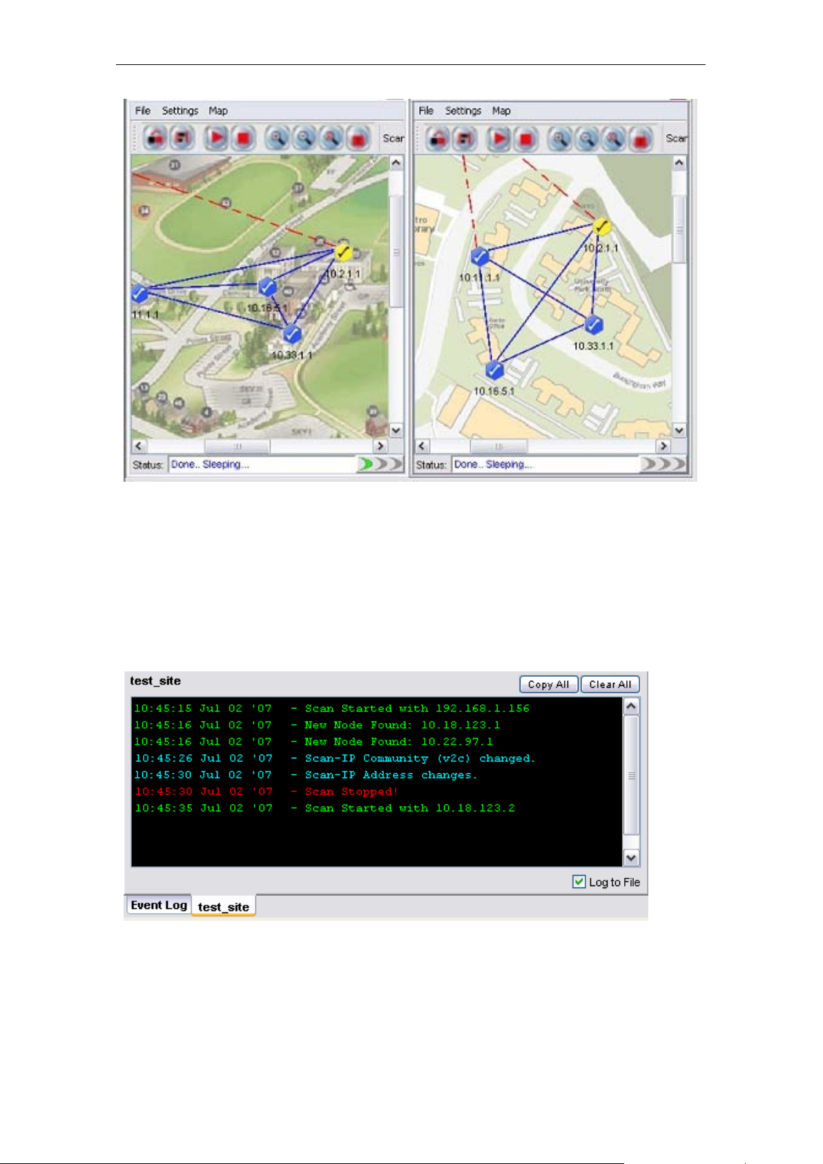
In order to change the vie w type, click the Tile button on t he main toolbar, or select View >
Tile from the menu bar. The tile mode arranges the topol og y maps in a grid la yout. To convert
the view mode to casc ade, hit t he Cascade button, or View > Cascade. T he fol lowing f igures
illustrate the difference between the two modes .
(Cascade mode)
PLANET Mesh Network Manager Guide
Page 27
PLANET Mesh Network Manager Guide
Page 27 of 126
(Tile Mode)
4.2.3.7 Status Pane
The status pane is located at the bottom of the map container. It displays the nodes’ status
with the time and date; enable users to keep track of the changes in the topology.
The type of message can be varied by the color of the text. Green text indicating positive
message such as sc an started or no des found; r ed tex t s hows the n egati ve mes sage such as
nodes down or tim eout; whereas cyan text dis playing system message, for instance, s ystem
settings changed.
PLANET Mesh Network Manager Guide
Page 28
PLANET Mesh Network Manager Guide
Page 28 of 126
The Copy All and C lea r All buttons on t he top of the pane perf orms the cop y an d delet e text
action in the status pane. Tick the checkbox at the bottom to log th e status message to the
alarm log file, which will be saved to the folder Alarm_Log at the install directory.
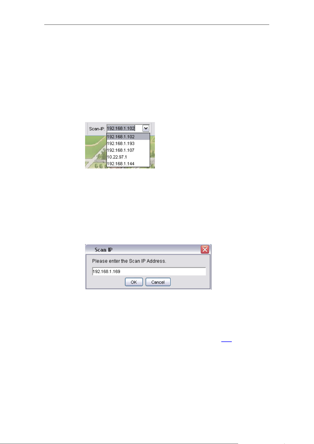
4.2.3.8 Scan IP Address
The Scan IP Address is the I P Address that the scannin g process uses when initiate a scan
for a SNMP Map.
User might enter the IP Address at the drop down list, or choose from the list. In order to
apply the new Scan I P, user is required to restart the network scanning. ( A running scan will
be stopped when a new IP Address is selected.)
On the other hand, the Scan IP can also be set by selecting Settings > Scan IP from the map
container’s toolbar. A window would appear to prompt user for the new IP Address. Hit the OK
button to apply the change.
4.2.3.9 SNMP Community / Passwords (for Scan-IP)
The PLANET Mesh Network Management Tools use the SNMP method to read the t opology
of the network. T here are two types of SNMP key used for the topo logy scan, which are the
Scan-IP key and the AP Unit key. More details about the latter please click
Commonly, the use of SNMP varies b y its version. If a us er select v ersion 2c, the SNMP key
to use is a community; on the other hand, if version 3 is used, the SNMP key will be a
SNMPv3 usernam e, with its c orres ponding a uthent icat ion pass word and privac y pass phrase.
As you can see throughout this document, every feature that implements SNMP will have
both options (use version 2c or 3).
PLANET Mesh Network Manager Guide
here.
Page 29
PLANET Mesh Network Manager Guide
Page 29 of 126
Basically, the Scan-IP ke y is the SNMP ke y tha t used for the Scan-I P which initiat es the scan.
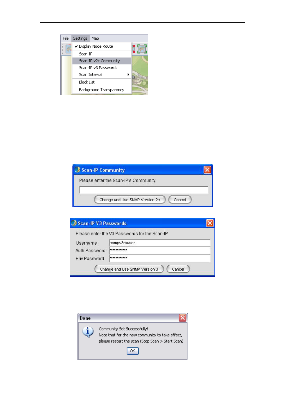
In order to configure the community of the Scan-IP, select Settings > Scan-IP v2c
Community from the map container menu. On the other hand, select Sett ings > Scan-I P v3
Passwords to change the SNMP versio n 3 Passwords. A window would turn up to prom pt
user for the new key(s).
Press Change and Use SNM P Version X button t o proceed. If the change is successfully,
the following dialog box wo uld app ear, to remind user to r eset th e scan i n order to let the ne w
community or passwords to take effect.
PLANET Mesh Network Manager Guide
Page 30
PLANET Mesh Network Manager Guide
Page 30 of 126
The default value for Scan-IP:
Community: public
Username: snmpv3rouser
Password: snmpv3password
Passphrase: snmpv3passphrase
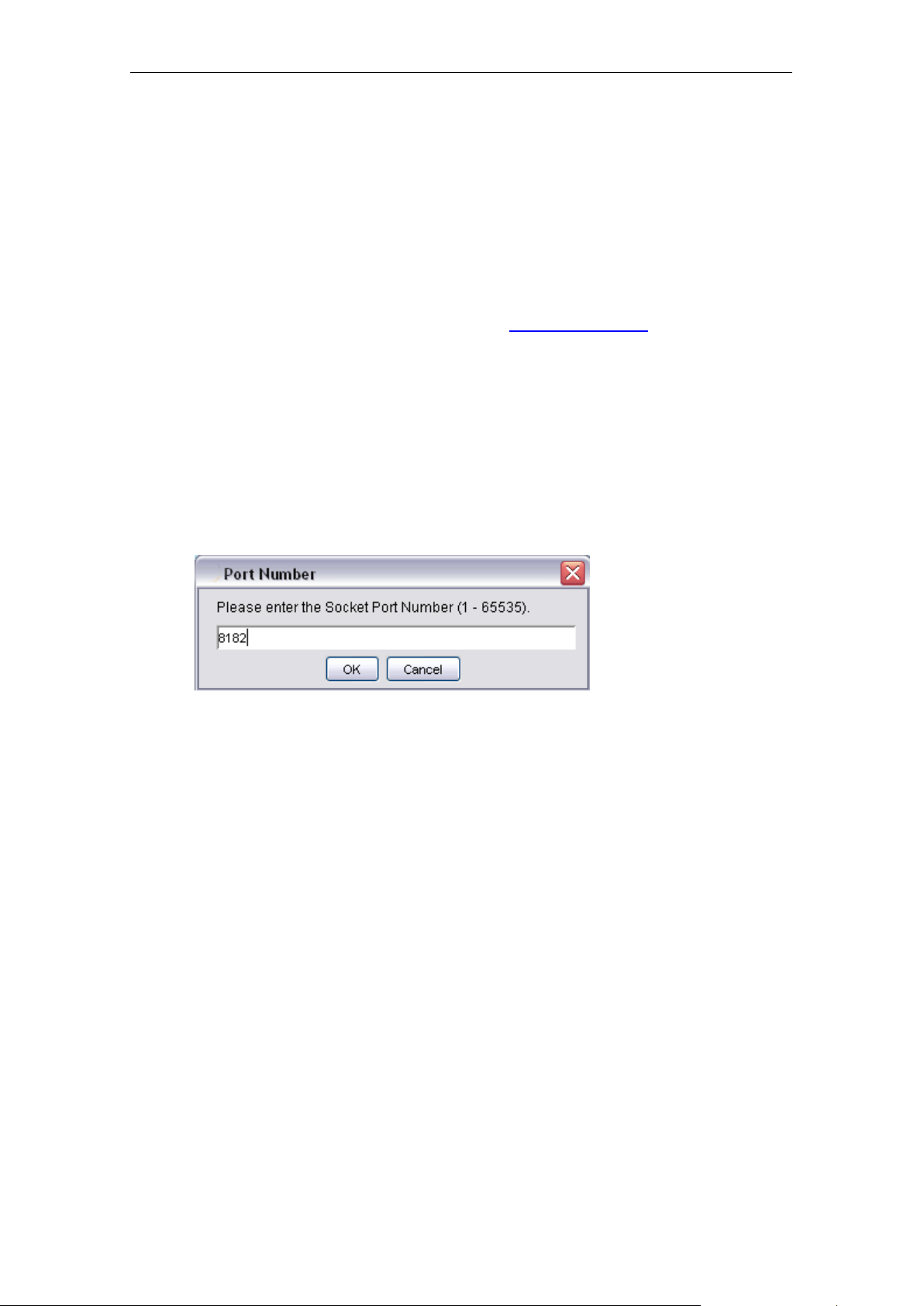
4.2.3.10 Socket Port
The notification of an AP node is sent according to its NMS Address Table. The table defines
the IP Address and port number of the destination (NMS). For instance, if the admin has
added a table entry with port number 8000 at the AP, the NMS user can change the socket
port number to 8000 in order to receive the notification.
In order to update the socket port, select Settings > Socket Port from the menu bar. A dialog
box would appear on the screen to prompt for the port number, which range from 1 to 65535.
Hit OK to confirm the change.
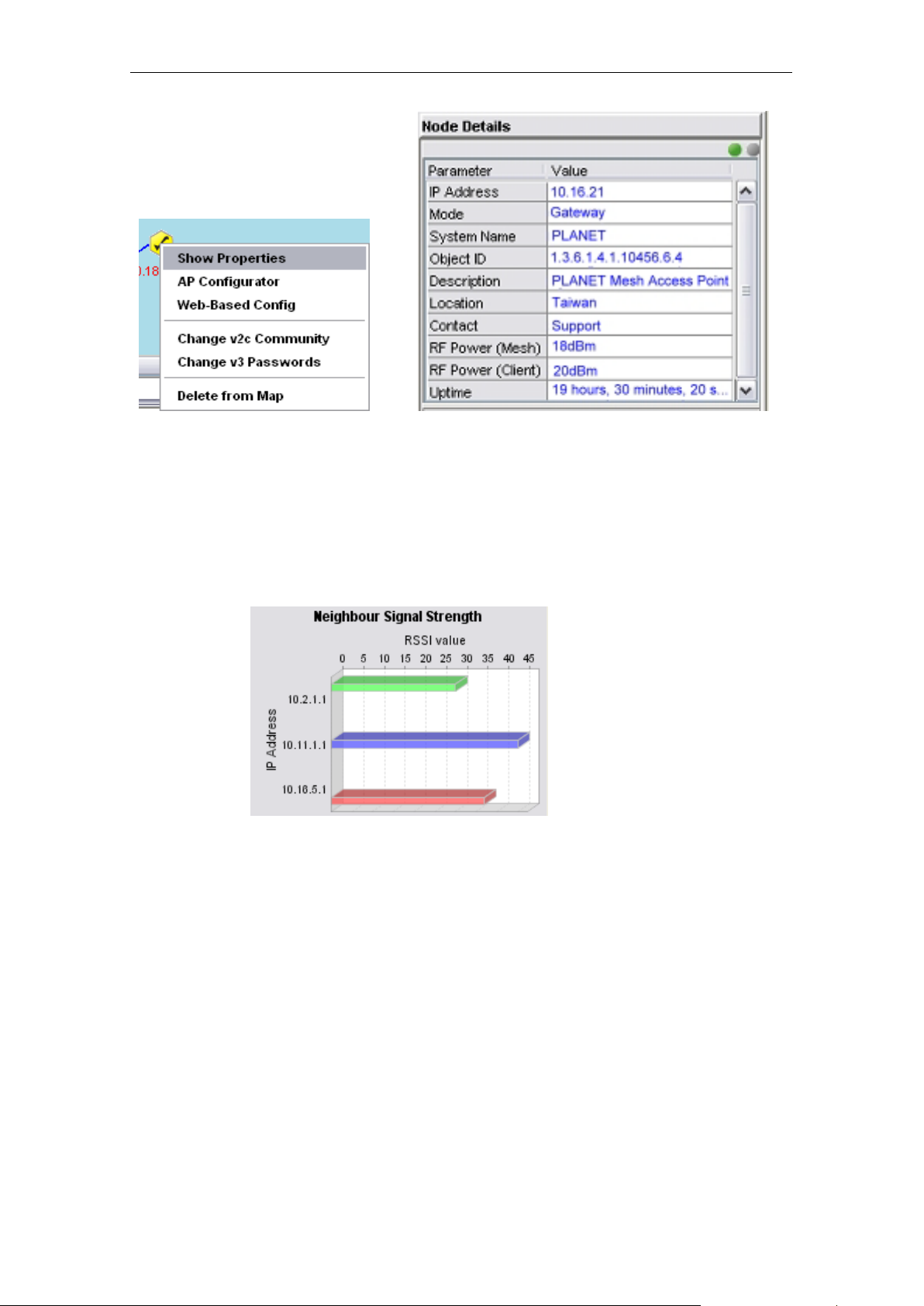
4.2.3.11 SNMP Com m uni ty / Passwords (for AP Unit)
In case if a Mesh A P utilizes a different community o r passwords from the others , the NMS
might fail to read the top ology from it. Hence, user might nee d to edit the individual AP unit
SNMP keys, by right-click the desired activ e node. Select Change v2c Community from the
popup menu to change the community; or click Change v3 Passwords to change the v3
keys; enter the correct value in the dialog box and click Change and Use SNMP Version X.
PLANET Mesh Network Manager Guide
Page 31

PLANET Mesh Network Manager Guide
Page 31 of 126
Note that the AP Unit Keys is also used for r ead the
default SNMP version and keys of the Mesh AP is inherited from the Scan-IP that found them.
Node Details and Clien t Properties . The
4.2.3.12 Scan Interval
The scan interval defines the time interval between e very round of scanning. B y default, the
NMS will sl eep for 10 seconds once a net work s can is com pleted. User m ay change t he tim e
interval by select Settings > Scan Interval, and choose the desired time interval. The
available options:
PLANET Mesh Network Manager Guide
Page 32

PLANET Mesh Network Manager Guide
Page 32 of 126
10 seconds
30 seconds
60 seconds
120 seconds
150 seconds
The changes will take effect immediately.
4.2.3.13 Impor t Ba ckground Image
User can change the bac kground of the topolo gy map by import an y desired image file fr om
other resource. Click on the Import Background Image button, or select File > Import
Background from the map container’s menu bar. A file chooser window would appear, to
prompt user for the image file that wished to import.
PLANET Mesh Network Manager Guide
Page 33

PLANET Mesh Network Manager Guide
Page 33 of 126
After select a image f ile (.jpg, .gif, .png ..etc), click the Open
loaded into the topology map.
4.2.3.14 Map P r int
button. The new im age will be
The NMS also provide the printing feature, where user is able to print the whole map by just
select the File > Print Map option from the Map Container menu bar. Then it will redirect the
map to the printer connected to the terminal where you run the NMS.
PLANET Mesh Network Manager Guide
Page 34

PLANET Mesh Network Manager Guide
Page 34 of 126
4.2.3.15 Map Zoom
As a graphical sol ution for a network system , the PLANET Mesh Net work Managem ent Tools
provides the zooming f eatur e for t he user to m anage the top olog y map m ore efficiency. Three
options are available: Zoom In, Zoom out and Zoom Fit.
The Zoom In and Zoom O ut feature enable us er to e nlarge and minim ize, respec tively, at the
scale of 25%. Whereas the Zoom Fit f eature will resi ze the topolog y map to the m ost suitable
size to fit in the screen. The following figures illustrate the effect of the zoom features.
(Original size)
(Zoom In)
PLANET Mesh Network Manager Guide
Page 35

PLANET Mesh Network Manager Guide
Page 35 of 126
(Zoom Out)
(Zoom Fit)
4.2.3.16 Customize Map
This feature provides user the flexibility to change the look and feel of the topolog y map, by
replacing the exist ing AP unit im age and the l ink between APs. User c an im port their cust om made icon, or adjust the color to fit their visual requirement.
The method is straight forward. Select Settings > Customized Map from the NMS menu bar,
to invoke the Map Customization Tool window, as illustrated.
PLANET Mesh Network Manager Guide
Page 36

PLANET Mesh Network Manager Guide
Page 36 of 126
PLANET Mesh Network Manager Guide
Page 37

PLANET Mesh Network Manager Guide
Page 37 of 126
Pattern
space2)
Preview
20, 0, 0, 0
20, 10, 20, 10
5, 10, 5, 10
20, 3, 10, 3
20, 10, 30, 5
As you can see from the f igures , the cust om ization ca n be d ivid ed to t wo par ts, th e Node a nd
the Link. At the Node part, user may select the icon t hat need to be updated, and then f ill in
the path of the ne w image (or click the “…” button to choose from the file chooser windo w).
Hit the Update button to update th e new image icon. Besid es, user can a lso decide whether
to show the indication of the AP-unit, which is the IP Address, by using the available
checkbox; and alter th e foreground color of the IP Ad dress using the “…” butto n to select a
desired color from the popup window. Hi t the Save & Apply Changes button to c ommit the
changes. The Use Def ault button enables the user to r estore the default s ettings of the AP
unit look and feel.
Meanwhile, in order to c hange the st yle of the link, s witch the Map C ustomization T ool to the
Link page. User can ch ange the color by hittin g the “ …” button to s elect a des ired color from
the popup window. T hen k ey in the t hicknes s of the link and i ts dashin g patter n. T he dashing
pattern defines the way the dashed link look like. T he following table ex plains how to use the
dashing pattern. Af ter f il l in the data, user may click the Update but t on to up date t he image at
the preview. Once confir m the chang es, sel ect th e Sav e & Apply Chan ges button to commit
the change.
(line1, space1, line2,
Here is an example to show the effect of the map customization.
a) The original map
PLANET Mesh Network Manager Guide
Page 38

PLANET Mesh Network Manager Guide
Page 38 of 126
b) Select Map Customization Tool and change the gateway & relay icon
c) Switch to Link page and edit the attributes
d) The customized map will look like this now.
Note that, the chang es of the AP un it node and l ink applies to e very map create d or opened
on the NMS.
4.2.3.17 Background Image Transparency
This is a special to ol us e d t o a dj us t th e opacity of the bac kground image of th e to pol ogy map.
Select Settings > Background Transparency from the map container menu bar to allow
users to alter the tr ans pare ncy of the backgr ound to a le vel t h at th e APs and links are clear to
view.
PLANET Mesh Network Manager Guide
Page 39

PLANET Mesh Network Manager Guide
Page 39 of 126
View the following figures to see the effect of the transparency tool.
(100%)
(50%)
(10%)
The tool will be closed automatically when it loses focus (mouse click anywhere out from the
tool).
4.2.3.18 Block List
The Block List offers the NMS users a f iltering tool in the topolog y map. User can define the
IP Address to block, once the AP is block ed, it will be removed f rom the topology map, and
will not be added to the map even if it is detected by the NMS.
To move an IP to the block list, click the Blo ck List button on the toolbar, or select Settings >
Block List f rom the menu bar. A window will emerge, as sho wn by the figure above. Then
PLANET Mesh Network Manager Guide
Page 40

PLANET Mesh Network Manager Guide
Page 40 of 126
user can choose the node to block from the Available Nodes column. Select the IP, and hit the
Add button. The IP will be move over to th e Nodes to Block column. On the other hand, if
user wishes to undo the ste p, use the Remove button t o move the IP back to the available list.
The Ad d All and Remove All button perform the sam e oper ation b y moving every I Ps in the
list. Finally, hit the OK button to comm it the change. (Note: asteris k in the list sho ws the IP is
a gateway node).
The blocked IP Address will be saved into the map setting file when the user saves the
topology map. Hence the IP will still be blocked when the current map profile r eload in the
future.
4.2.3.19 Lock / Unlock
This feature is intended to prevent the user from dragging the node away from its current
position accidentall y. User can select Map > Lock AP from the menu bar or use the Lock
AP button on the toolbar to lock up the nodes on the map.
PLANET Mesh Network Manager Guide
Page 41

PLANET Mesh Network Manager Guide
Page 41 of 126
Conversely, click the Map > Unlock AP or Unlock AP butto n on the toolbar to release the
lock. Hence, once user has complete positions the nodes, turn on the lock.
4.2.3.20 Node details
The table next to the map container is the node details table. The table displays the properties
of the selected Mesh A P unit. In order to loa d the data, us er c an dou bl e-click on an active un it
(gateway or relay or client-relay), or right cl ick then choose the Show Properties item from
the popup menu.
PLANET Mesh Network Manager Guide
Page 42
PLANET Mesh Network Manager Guide
Page 42 of 126
As mentioned previous ly, the NMS use th e SNMP method to read the data. Henc e if the data
is failed to load, you may check the SNMP Community or Passwords. The t wo small circles
on the top of the table indi cate the status of the table. If the green circle is li ght up, it shows
the table is loaded completel y; if the orange circ le is light up, it means the table is loading th e
data, else if the circle to turn to red color, it indicates that the data loading is failed.
On the other hand, the b ar chart at the bottom of the table displaying the signal strength (in
RSSI) bet ween the selected AP and all its neighbour nodes. T he scale of the chart can be
enlarged by dragging the desired range of x-axis. Drag backward to reset the chart.
4.2.3.21 Client Properties
The client properties panel is loc at ed at t he other side of the map container. In order to initiate
the NMS to download the client details, hit on the Start button at the b ottom of the panel. In
case if there is m ore than one map is r unning, a menu would pop up to prom pt user to s elect
which map to be targeted. Once selected, the scanning will be started instantly.
PLANET Mesh Network Manager Guide
Page 43

PLANET Mesh Network Manager Guide
Page 43 of 126
The automatic ref resh feature of the client properties panel enab le the admin uses t he live
information regardi ng the cl ients assoc iated t o the Mes h AP unit disc overed by th e NMS. T he
panel will be refreshed once per minute. On the other hand, if user wishes to refresh the
panel manually, simply click the Refresh button at the bottom of the panel. While the
downloading is in pro gr es s, the butt ons will be replace d by a progress bar, showing the status
of the process. The NMS will download the information from every single node in th e target
map discovered. To s t op the scan, simply hit on the Stop button. The Target Map column
displays the name of the map where the client panel is scanning.
The panel is divided into t wo portions, the Client Pro perties and Client Signa l Strength. The
Client Properties portion dis play the details regarding the client, for instance the MAC Address,
channel number, link speed and the idl e time. In the case if there is no client associated t o
the AP, a message “No Client Found” will be displayed instead.
On the other hand, the Cl ient Signal Strength panel dis plays the signal str ength of the c lients
associated to the A P, in the unit of rssi. Similarly, if there is no client assoc iated to the AP, a
message “No Client Found” will be shown.
4.2.3.22 Get/Set using MIB Reader
This section describes briefly about the usage of the MIB Reader of the PLANET Mesh
Network Management T ools.
PLANET Mesh Network Manager Guide
Page 44

PLANET Mesh Network Manager Guide
Page 44 of 126
As illustrated, the c enter frame of the MIB Re ader consists of three parts, SN MP keywords,
description area an d output area. The SNMP keywords portion is th e area where user f ills in
the necessary parameter that n eed to perform any SNMP action. For instance, if the SNMP
version to use is version 1 or 2c, t hen the Community is the r equired f ield; else if vers ion 3 is
selected, then user need to fill in the username, authentication password, and privacy
password fields. The Input Value field is used when user wish to execute the SNMP Set
command.
The Description area displays the description of the selected MIB tree node; whereas the
Output area prints out the output of the SNMP action.
• Get Action
PLANET Mesh Network Manager Guide
Page 45

PLANET Mesh Network Manager Guide
Page 45 of 126
1. Select any tree node (make sure it is either read-only or read-write type)
2. Fill in the required parameter according to the version of SNMP to use.
3. Click the SnmpGet button on the toolbar.
4. The output should now display at the Output area.
• Set Action
1. Select any tree node (only read-write type)
2. Fill in the required parameter according to the version of SNMP to use.
3. Enter the value to be s et at the In put Value column. You may refer the Syntax
column to ensure the type of the input (eg: Integer, DisplayString..).
4. Click the SnmpSet button on the toolbar.
5. The Output area will display the result of the action, either “(Set
Successfully…)” or “(Set Failed…)”.
• Read Tab le A ction
1. Select a table tree node
2. Fill in the required parameter according to the version of SNMP to use.
3. Click the Load Table button on the toolbar.
4. The Output field should display the whole table now.
5. Use the Refresh Table to reload the table.
• Add Table Row Action
1. Repeat the first three steps of Read Table Action
2. Then enter the table valu es in the Input Value field. Values are separated by
a comma (,). (see the following figure)
3. Click the Add Table Row button on the toolbar.
4. The new entry should be added to the table.
• Delete Table Row Action
1. Repeat the first three steps of Read Table Action
2. Select the entry that you wish to remove from the table.
3. Click the Delete Row button on the toolbar.
4. A popup window would appear to ask for your confirmation to delete the
5. The selected entry should be removed from the table.
• Snmp Walk Action
1. Select any tree node. (It can be a table, scalar or even the main node)
2. Fill in the required parameter according to the version of SNMP to use.
PLANET Mesh Network Manager Guide
selected entry. Hit OK to proceed.
Page 46

PLANET Mesh Network Manager Guide
Page 46 of 126
3. Click the SnmpWalk button on the toolbar.
4. The output should no w displa y at the Output ar ea. It could tak e some tim e to
fetch all the data if the selected data is large.
Note: Please tr y to avoid Add or De lete the SNMP Table entry of the customized -MIB, since
there are som e tables wh ich ar e i ntern al l y cor rel at e d, s uc h as VLAN table and Wireless table.
Setting the table incorrectly would cause severe corruption in the system.
4.2.3.23 Load/Unload MIB
The MIB Reader of the NMS includes the feature to loa d and unload the MIB file from other
resource. Therefore, instead of the customized MIB, user can load other standard MIB into
the MIB Reader as well to read the parameter of the managed device.
In order to load a MIB, click on the Load button on the top of the MIB tree. A file chooser
window would popup, to prompt user to enter the desired MIB file. Click Open to load the file.
On the other hand, the Unload button nex t to the Load button would unlo ad the existin g MIB
in the tree. Select the u nwanted MIB, click on the Unload button. A confirmation dialo g box
would turn up, to ge t confirmation from the user to r emove the selected MIB. C lick the Yes
button to proceed.
PLANET Mesh Network Manager Guide
Page 47
PLANET Mesh Network Manager Guide
Page 47 of 126
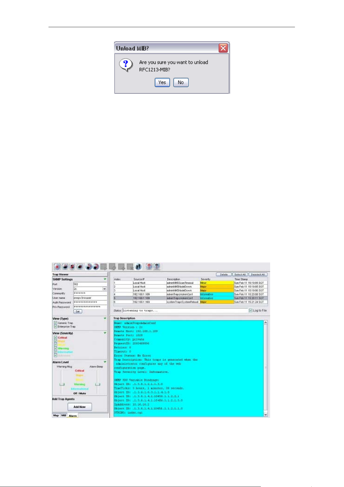
4.2.3.24 Alarm Table
The Alarm Table of the PLANET Mesh Network Management Tools enable user to ch eck on
the traps and notifications caught b y the trap rec eiver. The entries are read-only, and shall be
deleted once they were resolved or reviewed.
In order to start list en to th e traps, hit t he Start butt on at the toolbar or select Settings > Start
Trap from the menu bar. Select the Stop button, or Settings > Stop Trap to stop the trap
listener. User can change the SNM P Trap community or passwords at the available colum ns
and hit the Set button. The checkboxes at the bottom of the settings section are the table
filtering options. Clear the select ion of the c heck box to hide the re lativ e entr y in the trap table.
Each level of severity is represented by a different colo r.
Select any entry from the alarm table, its description wil l be displayed at the Trap Descripti on
area at the bottom of the table. If you wish to rem ove the selected entr y, click on the Delete
button.
PLANET Mesh Network Manager Guide
Page 48
PLANET Mesh Network Manager Guide
Page 48 of 126
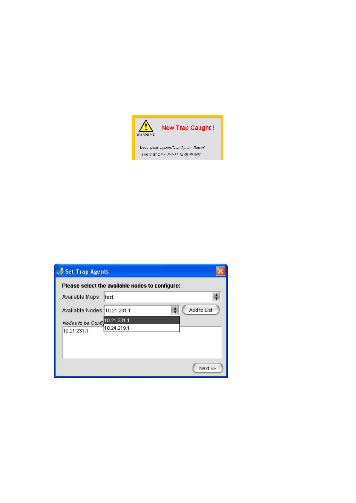
The Alarm Level area is to enable the user to d etermine the level of the warni ng message
popup and the alarm beep sound. User may drag t he slider to alter the leve l. For instance,
drag the slider of the w arning m es sage to Minor, the warning m ess age would no t popup if the
level of the alarm received is Warning or Informational. The following figures illustrate the
example of Warning Messa ge, which wil l be displa yed at the left bottom c orner of the s creen
when the trap is received.
4.2.3.25 Add Trap Agent
This feature is a wizard window, intended to assist the user to set one, or more than one node
to be the trap agent of the host system at the NMS, simultaneously.
Hit the Add Now button at the tra p vie wer m ode, to invok e the wi zard. At t he fir st pag e of the
wizard, user will be prompt to enter the IP Address of the desired nodes, to be set as alarm
agent. User can en ter the IP Address m anually, or select from the drop down list provided.
Click Next to proceed.
PLANET Mesh Network Manager Guide
Page 49

PLANET Mesh Network Manager Guide
Page 49 of 126
Then, enter the required SNMP keywords, such as version and community. Click Set to
proceed or Back to back to the first step.
Once the configuration is d one, click Proceed button to proceed to reboot page, or Back to
the previous page.
If Proceed is pressed, the following page will be displayed. User may select the IP Address of
the node configured just n ow to be rebooted. In case if user is wished to reboot the device
manually afterwards, c lick Reboot Later. On the other hand, hit th e Reboot now & Close
button to start reboot the devices.
PLANET Mesh Network Manager Guide
Page 50

PLANET Mesh Network Manager Guide
Page 50 of 126
Once the AP unit is rebooted completely, it will contain the information of the Alarm Host
System in the NMS. Hence, it will redirect the alarm message and notification to the NMS
when there is any.
4.2.3.26 Vi ew Log Files
There is a feature in the NMS allow the user to back-track the log files of the system. Select
View > View Log Files from the NMS menu bar to invoke a new dialog box, as shown at the
following figures.
Then user can select the type of log to view, including Status Log and Alarm Log. Key in the
desired file name, or hit the button next to the column to select the file, and select the Reload
button to load the content of the file.
PLANET Mesh Network Manager Guide
Page 51

PLANET Mesh Network Manager Guide
Page 51 of 126
4.2.3.27 Show Route
When user moves the mouse over the plotted AP unit on the topology map, a small blue
dialog would appear on the screen, displaying the routes of the selected unit. The route
describes how the AP link t o the other n odes in the sa me m esh network, as illustrated by the
figure below.
The figure above shows the node 10.28.43.1 is currently connected directly to 10.30.45.1,
10.22.157.1, and 10.19.49.1.
PLANET Mesh Network Manager Guide
Page 52

PLANET Mesh Network Manager Guide
Page 52 of 126
Whereas the figure above illustrates how the routes are displayed when nodes are not directly
connected. From the exam ple, node 10.29.19 4.1 a nd 10.2 2.202.1 are not directl y conn ected.
Instead, the connecti on between them is estab lished via node 10.27.1 92.1, according to the
route box.
If user would like to disable this feature, please select Settings > Display Node Route from
the map container menu bar.
PLANET Mesh Network Manager Guide
Page 53

PLANET Mesh Network Manager Guide
Page 53 of 126
4.2.3.28 Create VPN Connection
If user would like to s can a network through the backbone line (WAN), a VPN Connection is
required in order to create the communication link between the NMS and the Mesh APs
discovered through a VPN Server.
To c reate a new VP N Connection, use th e New Connection wizard of W indows. In order to
start-up the wizard, open the Network Connections Page (Start Menu > Control Panel >
Network Connections), then select New Connection Wizard. When the wizard turn up,
follow the following steps to do the set up: (*refer to the following screen shots)
Introduction – Welcome page of the wizard
PLANET Mesh Network Manager Guide
Page 54

PLANET Mesh Network Manager Guide
Page 54 of 126
Network Connection Type – Select Connect to the network at my workplace and
click Next button
Network Connection – Select Virtual Private Network and click the Next button
PLANET Mesh Network Manager Guide
Page 55

PLANET Mesh Network Manager Guide
Page 55 of 126
Connection Name – Enter a desired Connection Name and hit the Next button
Public Network – Select Do not dial initial connection and press Next button
PLANET Mesh Network Manager Guide
Page 56

PLANET Mesh Network Manager Guide
Page 56 of 126
VPN Server Select ion – Enter the host n ame or the IP Address of the VPN Se rver
that you wish to connect, and click the Next button
Complete – Click Finish to complete the set up
After the shortcut is cr eated, user is required t o go to the Properties page, b y right-click on
the shortcut icon, and t hen c hoose fr om the popu p m enu. Alternat ivel y, it can be opened from
the Connect page, as shown:
PLANET Mesh Network Manager Guide
Page 57
PLANET Mesh Network Manager Guide
Page 57 of 126
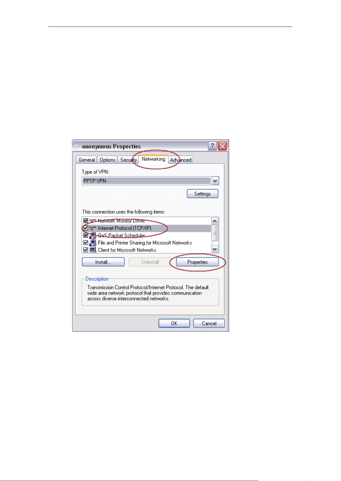
At the Connection Properties window, perform the following steps:
Select the Networking Tab at the top of the page
Select PPTP VPN in the Type of VPN field.
Select the Internet Protocol (TCP/IP) from the available list
Hit the Properties button to configure the item’s properties
At the TCP/IP Properties window, select the Advanced.. button, another window
(Advanced TCP/IP Settings) would appear.
At this window, make sure the Use default gateway on remote network option is
checked and click the OK button.
PLANET Mesh Network Manager Guide
Page 58

PLANET Mesh Network Manager Guide
Page 58 of 126
Enable the option
The configuration of the VPN is done.
4.2.3.29 Configure Mesh APs
Two methods are available to configure t he Mesh AP unit remotel y via the NMS,: thru Webbased Configuration Page or launch the AP Configurator. In order to inv oke an y of these two
methods, right click on any of the active Mes h A P unit on th e to po logy map (gateway or rel a y).
A popup menu would appear, as shown:
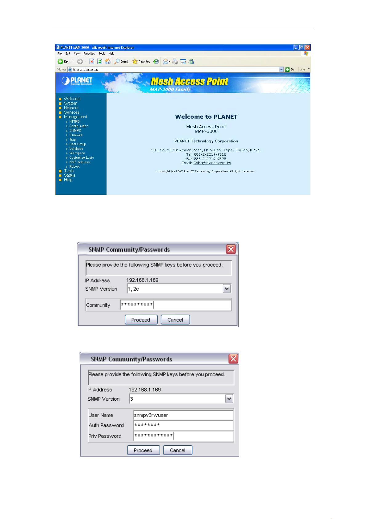
Select the AP Configurator or Web-Based Config option. T he following figure shows the
screenshot of the Web-based Configuration page.
PLANET Mesh Network Manager Guide
Page 59
PLANET Mesh Network Manager Guide
Page 59 of 126
If the AP Configurator is selected instead, a window would appear to prompt user for the
SNMP password and community, as shown:
(Version 1 and 2C)
(Version 3)
PLANET Mesh Network Manager Guide
Page 60

PLANET Mesh Network Manager Guide
Page 60 of 126
After enter the required passwords , c lick t he Proceed button to initiat e the AP Conf igurator. If
the password is incorrect, an err or mess age will show on the sc reen and urge us er to reenter
the password accurately. For more details regarding the AP Configurator, please refer to
next section.
the
4.2.3.30 Dis covery Tool
The discovery tool is an advance feature added to the NMS. Its main function is used to
discover the recognized AP unit locating in the same subnet. Hit the Discover button at the
bottom to initiate the scan. The APs found throughout the process will be displayed on the
table.
User may click on the entry on the table to view the information regarding the AP, such as
system name, MAC address and so forth. Further more, the selected unit can be configured
by using the drop-down list at the top of the Discover button, to open the AP-Configurator or
Web-based configuration page.
4.2.3.31 Vi ew Interface and Client Live Statistic
The new feature added in the latest vers ion of NMS, provides user a gr aphical and readab le
statistic table regarding the target M esh AP unit. The information that monitored by the live
stat portion includes the interfaces throughput, clients’ throughput, as well as the memory
status.
PLANET Mesh Network Manager Guide
Page 61

PLANET Mesh Network Manager Guide
Page 61 of 126
In order to invoke the live stat window, switch the NMS to the Map Container view, and then
look for the Live Stat Settings portion at the left b ottom corner. User may enter the IP Address
of the target node (or just click on the node on the map to load the IP) to be monitored, and its
corresponding SNMP Key. Hit the Start Live Stat button to initiate the window.
At the popup live stat wind ow, click the Start Polling button at t he top to start the live stat.
The window consists of tw o parts: the System Stat and the Client Stat. The System Stat page
displays the memor y status of the system and the statistic of the interfac es throughput. The
table will be updated at a c ertain inter val, which is set b y the Pol l In terval field at t he Li ve Stat
Settings corner.
PLANET Mesh Network Manager Guide
Page 62

PLANET Mesh Network Manager Guide
Page 62 of 126
The second page shows the throughput statistic of e ve r y client t hat associated to target no de.
The results of the transm ission and reception data pack et rate are displayed in the form of
graph. The table at the bottom of the gr aphs tabulat es the cli ent list with their r esp ective M AC
Address and online time. To stop the polling process, click the End Polling button at the top.
4.2.3.32 Logout Client
With the NMS, the administrator is able to log out and block the user from accessing the
network, by using the Logout and Block user button at the Live Stat Window
In order to remove the client, user must run the Live Stat Window. In the Client Stat portion,
the table at the bottom lists the client that has log on to the network. Select the client (Mac
Address) that to be removed, and hit the Logout and Block user button.
PLANET Mesh Network Manager Guide
Page 63

PLANET Mesh Network Manager Guide
Page 63 of 126
A window would appear on the screen to prompt user for the SNMP version to use and its
corresponding community or passwords. Click the Block User button once completed the
step, the selected client will be removed from the active client table, and added into the MAC
Access Table.
PLANET Mesh Network Manager Guide
Page 64

PLANET Mesh Network Manager Guide
Page 64 of 126
5 Configure the Mesh AP using AP
Configurator
5.1 Overview of AP Configurator
One of the main f eatures of the PLANET M esh Network Management Tools is its ability to
configure the Mesh AP remotely. In stead of the Web-Based Configuration page, user can use
the application software that designed specifically for the configuration of the Mesh AP,
namely the AP Configurator.
The AP Configurator utilizes the SNMP protocol to connect the user ’s terminal with the AP
over the network. The AP Configurator supports all SNMP version 1, 2C and 3 over UDP.
User may read and write the settings of the hardware through the SNMP agent running on the
device.
The figure below illustrates the screenshot of the AP Configurator:
PLANET Mesh Network Manager Guide
Page 65

PLANET Mesh Network Manager Guide
Page 65 of 126
5.2 How to use AP Configurator
This section briefly explains how to configure the AP with the AP Configurator commonly.
Before we proceed, let us have a quick view over the la yout of the user interface. Thru the
image at above, there is a tr ee at the left of the software. The tree lists all the configuration
items in the AP. Click on the item that you wish to view or alter; the relative page will be
loaded in the center frame. On the other hand, the menu bar on the top of the software can be
used to open the configuration page as well.
There is a status bar at the bottom of the page, where it displays the status of the data loading
and setting. In order to set the scalar values, perform the change, and click on the Save
Changes button. The Cancel button is to close the configuration page.
In case to configure any table data, notice th at there is a Status drop-dow n list at the bo ttom
of every table, as shown:
Select the type of ac tion yo u would lik e to per form : add, e dit or del ete a tabl e row. Then, click
the “>>” button next to the drop-down list. For add and edit operation, an extra area will
appear at the bottom of the drop down list, where it enable user to enter the table data. Hit the
Add or Edit button to complet e the operation. The area can be c losed by selecting the “X”
button at the top right corner.
PLANET Mesh Network Manager Guide
Page 66
PLANET Mesh Network Manager Guide
Page 66 of 126
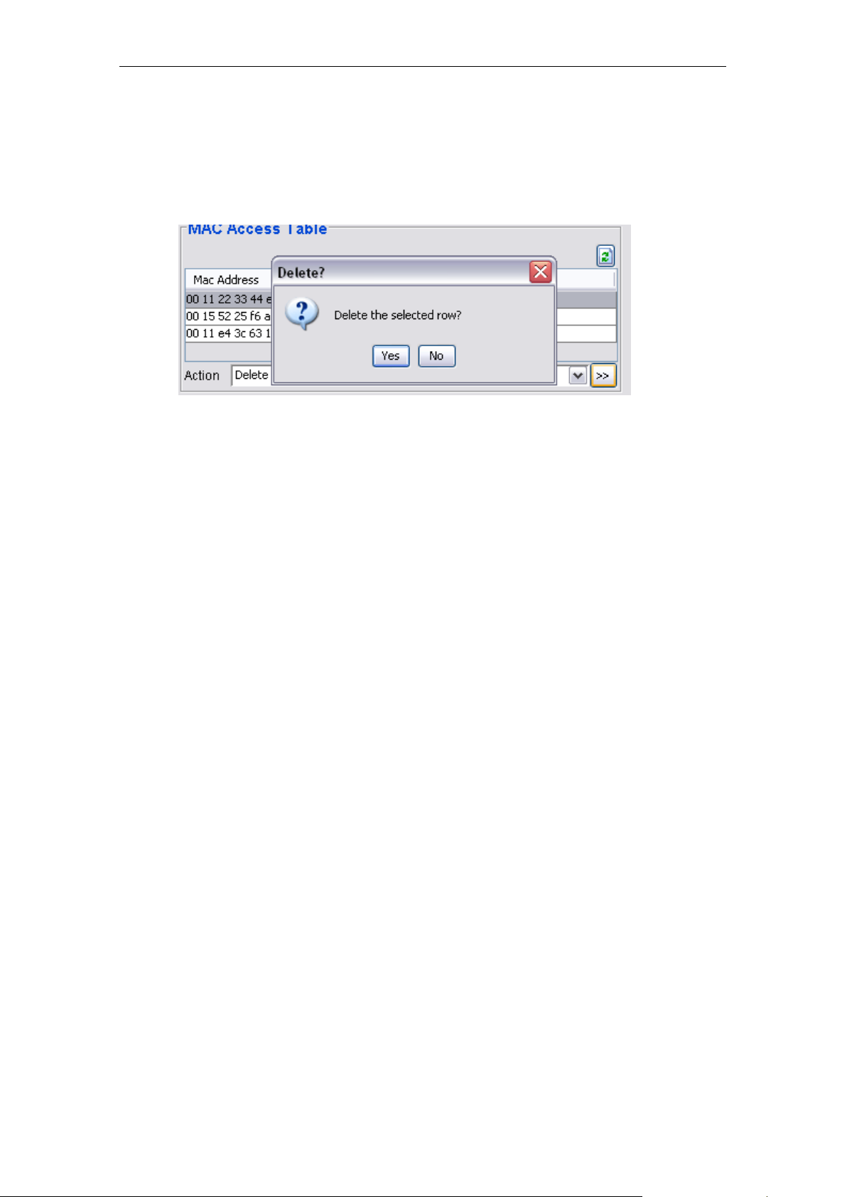
For delete action instead, select the table entry that wanted to be removed, click the “>>”
button next to the drop-do wn list. A warning message woul d appear to prompt user for their
confirmation to proceed with the operation. Hit Yes to proceed.
The Refresh button at the top of every table is used to reload the table.
PLANET Mesh Network Manager Guide
Page 67

PLANET Mesh Network Manager Guide
Page 67 of 126
to section 3.3.2 for more.
5.3 Configure the Mesh AP
At this section, we will loo k into every configuration pages of the Mesh AP one by one, and
briefly describe the parameters in the pages.
5.3.1 System > system
The System page is the general settings page of the AP.
Parameters:
1) System Name
• The generic name of the Mesh AP unit.
• Data type: Display String
2) System Location
• The generic physical location name of the Mesh AP Unit
• Data type: Display String
3) System Mode
• The operation mode of the Mesh AP unit
• Options: Gateway, Relay, Client-relay, Layer 2 Gateway, Layer 2 Relay
Gateway Layer 3 Gateway Mode. In a Mesh network Gateway mode is the
path to the Internet for the whole Mesh network behind.
WAN port is active and will be used for Internet Connection.
Three types of Internet connection will be available, please refer
PLANET Mesh Network Manager Guide
Page 68

PLANET Mesh Network Manager Guide
Page 68 of 126
setting is required.
edge of the whole mesh topology.
network.
between WAN, LAN, Mesh backhaul and WiFi.
Relay Layer 3 Relay Mode. Relay mode can help to route between
mesh backhaul and local WiFi/LAN network. Also, a Relay mode
Mesh AP can help to route the packets from other Relay node to
the destination IP subnet or Gateway.
WAN port is disabled at this mode. At the same time no WAN
Client-Relay Layer 3 Client-Relay Mode.
At this mode, the Mesh node can only route between local
WiFi/LAN network to mesh backhaul. It will not help to route
packets from other Relay node. This mode can be used to reduce
the unnecessary routing especially if this Mesh node is in the
Layer 2 Gateway Layer 2 Gateway Mode.
At this mode, the Mesh AP can be viewed as a bridge. This
bridge can bridge between WAN, LAN, Mesh backhaul, and WiFi.
As a Gateway, the WAN interface will turns into the public bridge
port that connects to the existing Ethernet network.
Be noted, only ONE Gateway is allowed in the same Mesh
Layer 2 Relay Layer 2 Relay Mode.
4) Contact Name
• The name of the contact person / network administrator
• Data type: Display String
5) Contact Email
• The E-mail address of the contact person / network administrator
• Data type: Display String
6) Contact Phone
• The phone number of the contact person / network administrator
• Data type: Display String
7) Description
At this mode, the Mesh node act as a mesh relay that can bridge
• A short description regarding the managed device (Mesh AP)
• Data type: Display String
8) Object ID
• The Object ID (OID) of the Mesh AP specified to support the SNMP service
• Read-only data
PLANET Mesh Network Manager Guide
Page 69

PLANET Mesh Network Manager Guide
Page 69 of 126
5.3.1.1 System > Syslog
The Syslog is a system feature to send the system log messages to a remote server.
Parameter
1) Enable Syslog
• A checkbox to enable or disable the syslog feature.
2) KLOG
• A checkbox to enable or disable the Kernel Log service
3) Enable Remote Syslog
a. A checkbox to enable or disable the remote syslog server service
4) Remote Syslog Address
• The address of the remote syslog server, who will receive all the syslog message
• Data type: DNS String
5.3.1.2 System > Advanced Tuning
The Advance Tuning panel is divided to two parts, the connection tracking parameters and
the wireless distance. The Connection tracking portion determines the seconds of various
timeout parameters, where as the latter define the estimate operating distance in meters, for
the radio available in the device. Use the reset button to refill the value fields with the default
values.
PLANET Mesh Network Manager Guide
Page 70

PLANET Mesh Network Manager Guide
Page 70 of 126
Parameters:
1) Maximum session
• Maximum allowable IP connection tracking session.
• Range: 4096 ~ 212368; Default: 10000 sessions
2) Generic Timeout
• Timeout value in seconds (s) for generic connection track entry.
• Range: 50 ~ 1200; Default: 600 seconds.
3) ICMP Timeout
• Timeout value in seconds (s) for ICMP entry.
• Range: 10 ~ 60; Default: 30 seconds.
4) TCP Close Timeout
• Timeout value in seconds (s) for TCP close.
• Range: 5 ~ 30; Default: 10 seconds.
PLANET Mesh Network Manager Guide
Page 71

PLANET Mesh Network Manager Guide
Page 71 of 126
5) TCP Close Wait Timeout
• Timeout value in seconds (s) for TCP close wait.
• Range: 10 ~ 120; Default: 60 seconds.
6) TCP Established Timeout
• Timeout value in seconds (s) for established TCP.
• Range: 600 ~ 864000; Default: 3600 seconds.
7) TCP Finished Wait Timeout
• Timeout value in seconds (s) for TCP finished wait.
• Range: 10 ~ 3600; Default: 120 seconds.
8) TCP Last ACK Timeout
• Timeout value in seconds (s) for TCP last acknowledgement.
• Range: 10 ~ 60; Default: 30 seconds.
9) TCP SYN Receive Timeout
• Timeout value in seconds (s) for TCP SYN receive.
• Range: 10 ~ 120; Default: 60 seconds.
10) TCP SYN Sent Timeout
• Timeout value in seconds (s) for TCP SYN sent.
• Range: 10 ~ 240; Default: 120 seconds.
11) TCP Time Wait Timeout
• Timeout value in seconds (s) for TCP time wait.
• Range: 10 ~ 240; Default: 120 seconds.
12) UDP Timeout
• Timeout value in seconds (s) for UDP.
• Range: 10 ~ 60; Default: 30 seconds.
13) UDP Stream Timeout
• Timeout value in seconds (s) for UDP stream.
• Range: 10 ~ 360; Default: 180 seconds.
14) Radio 1 distance
• Specify the operating radius in meter (m) of radio 1.
• Range: 100 ~ 10000; Default: 400 meters.
15) Radio 2 distance
• Specify the operating radius in meter (m) of radio 2.
• Range: 100 ~ 10000; Default: 400 meters.
16) Country
• Select the operating country of the wireless interface.
17) Outdoor Mode
• Enable or Disable the outdoor mode for the wireless interface.
• Default: Enable.
PLANET Mesh Network Manager Guide
Page 72

PLANET Mesh Network Manager Guide
Page 72 of 126
18) External Channel Mo de
• Enable or Disable the external channel mode for the wireless interface.
• Default: Disable.
5.3.1.3 Network > Ne twork
The network panel defin es the DNS settings. T his DNS service trans lates the domain n ame
into IP Address form , which rec ognized b y the In terne t. If the pr im ary server fai led to p erform
the translation, the secondary server will take over the process.
Parameters:
1) Primary DNS
• Define the Primary DNS Server IP Address.
• Data Type: IP Address
2) Secondary DNS
• Define the secondary DNS Server IP Address
• Data type: IP Address
3) Domain
• An optional domain name for the DNS client
• Data type: DNS String
4) Default Gateway
• The default gateway IP Address for the static IP Address
• Data type: IP Address
PLANET Mesh Network Manager Guide
Page 73
PLANET Mesh Network Manager Guide
Page 73 of 126
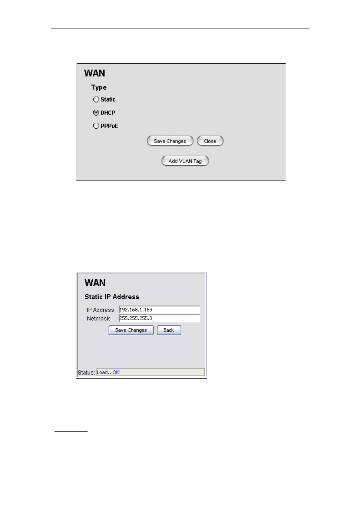
5.3.1.4 Network > WAN (MAP-3100 only)
Define the type of WAN interface to use. Three options are available: Static, DHCP, and
PPPoE. If user wish es to change the t ype to dynamic, s elect the DHCP, then click the Save
Changes button. If Static or PPPoE is selecte d instead, the Configure button will lead the
user to the configuration page of the type.
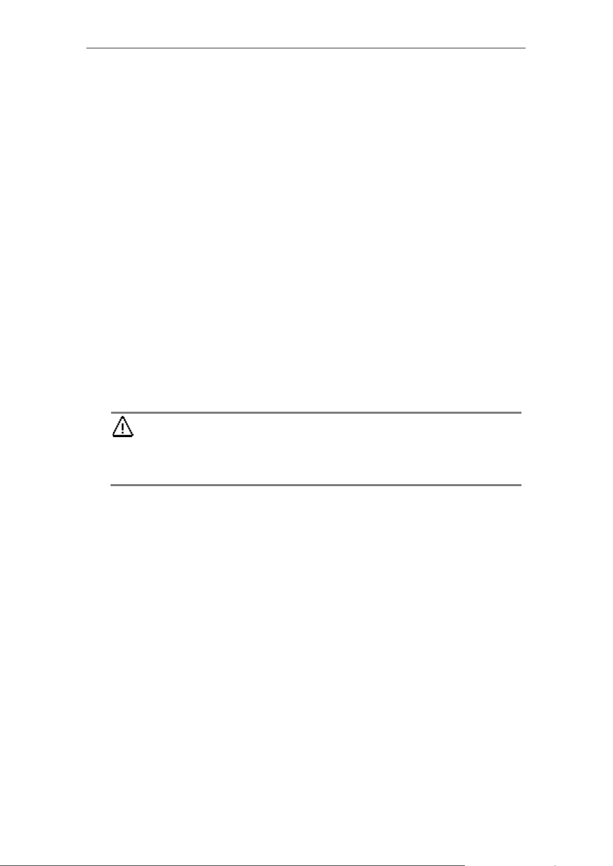
• Network > WAN > Static
Enter the Static IP Address and its netmask, clic k the Save Changes button to activat e the
Static WAN interface type. Hit the Back to go back to the WAN Type configuration page.
Parameters:
1) IP Address
• The static IP Address for the WAN interface
• Data type: IP Address
PLANET Mesh Network Manager Guide
Page 74

PLANET Mesh Network Manager Guide
Page 74 of 126
2) Netmask
• The netmask for the Static IP Address.
• Data type: IP Address
• Network > WAN > PPPoE
Fill in the PPPoE ’s username and password, t hen click the Save Change s butt on to activate
the PPPoE WAN interface t ype. Hit the Back but ton to back to the WAN Type configuration
page.
Parameters:
1) Enable PPPoE
• A checkbox to enable or disable the PPPoE service.
2) Username
• The username of the PPPoE client
• Data type: Display String
3) Password, Confirm
• The password corresponding to the username of the PPPoE client
• Must key in the same input at the Confirm field to avoid mistakes
• Data type: Display String
PLANET Mesh Network Manager Guide
Page 75

PLANET Mesh Network Manager Guide
Page 75 of 126
1. If your Ethernet network that connect to WAN port supports VLAN
Maximum is 15 virtual WAN interfaces are allowed.
• Network > WAN > Add VLAN Tag
Note that there is an Ad d VL AN Tag button at the WAN page. Press the button would open
the VLAN Tag page, where user may define the VLAN ID for a desired WAN interface.
Note
Parameters (VLAN Tag List columns)
1) ID
• The VLAN-ID
• Data type: Integer, in between 1 and 4096
tagging and you plan to make the Mesh Network route for different
purpose, you can use the “Add VLAN Tag” button to create different
VLAN for WAN interface.
2. O nl y the default WAN is un-tagged. Any other newly inserted WAN
interface will be tagged follow the ID setting that range from 1 to 4095.
PLANET Mesh Network Manager Guide
Page 76

PLANET Mesh Network Manager Guide
Page 76 of 126
2) Type
3) IP
4) Subnet
5) Comment
• The type of the WAN-VLAN defined.
• Available option: Static and DHCP
• The IP Address of the interface.
• This field is disabled if the Type chosen is DHCP
• Data type: IP Address
• The corresponding subnet for the IP Address of the interface.
• This field is disabled if the Type chosen is DHCP
• Data type: IP Address
• Optional comment regarding the table entry
• Data type: Display String
6) Status
• Enable or disable the table entry.
• Available option: Enable and Disable
Hit the Back button to go back to the WAN-Type page.
PLANET Mesh Network Manager Guide
Page 77

PLANET Mesh Network Manager Guide
Page 77 of 126
5.3.1.5 Network > VLAN
The page is displa ying the VLAN Table which is showing the activat ed VAP of the Mesh AP.
There are total of 16 VLANs available in the device. In order to activate an inactive VAP,
choose an entr y from the Inactive VAP List, then click the Edit Inactive VAP button. Then the
Edit Inactive VAP – VLANx panel would appear. Similarly, to edit or disable an active VAP,
user can select t he entry from the table, and hit the Edit Active VAP. Fill in t he following
parameters:
1) ID
• The ID for the VLAN interface.
• The value is ranged between 1 to 4095, where 0 is reserved for VLAN0
2) Type
• The type of the VLAN
• The available options are static and dynamic
PLANET Mesh Network Manager Guide
Page 78
PLANET Mesh Network Manager Guide
Page 78 of 126
1. ONLY VLAN 0, the default VLAN, is un-tagged packets. For VLAN 1 to
connect wired device for different VLAN.
3) IP Address
• The IP Address of the selected VLAN interface
4) Netmask
• The Netmask for the IP Address
5) Address Type
• The type of the IP Address, either NAT or Routable
6) Comment
• An optional comment regarding the table entry
7) Active
• The status of the VAP
• Set to Active to enable an inactive VAP; set to Inactive to disable an active VAP.
Finally click the Save Changes button to commit the changes.
Note
VLAN 15, it will be tagged packets at LAN interface after it is enabled.
And for Wireless interface, different SSID are required for different
VLAN.
2. The connected LAN device should support VLAN tagging if you plan to
PLANET Mesh Network Manager Guide
Page 79

PLANET Mesh Network Manager Guide
Page 79 of 126
5.3.1.6 Network > Mesh
The Mesh configuration page read the data from the wireless interface, ath0. Select the
Wireless Settings button to view or edit the corresponding data.
Parameters (Mesh Configuration)
1) IP Address
• IP Address for the Mesh interface
• Data type: IP Address
2) Netmask
• Netmask for the IP Address of the Mesh interface
• Data type: IP Address
PLANET Mesh Network Manager Guide
Page 80

PLANET Mesh Network Manager Guide
Page 80 of 126
3) Comment
• An optional comment regarding the Mesh interface
• Data type: Display String
4) Active
• The status of the Mesh interface, either active or inactive.
Parameters (Wireless Settings)
1) MAC Address
• The Mac Address of the Mesh interface
• This is a read-only parameter
2) Mode
• Define the mode of the Mesh interface
• In this case, the mode is fixed to AD-HOC
3) Band
• The band to use
• Three options available: 802.11a, 802.11b, and 802.11g
4) ESSID
• The identifying name of a wireless access point’s network
• Data type: Display String
5) Frequency
• The operating frequency of the ath0 wireless network interface in Mega Hertz.
6) Beacon Interval
• The beacon interval in milliseconds
• Data type: Integer, in between 20 and 1000
• Default value is 100
7) RTS Threshold
• The RTS Threshold value
• Data type: Integer, in between 256 and 2346
• Default value is 2346
PLANET Mesh Network Manager Guide
Page 81

PLANET Mesh Network Manager Guide
Page 81 of 126
8) Fragment Threshold
• The Fragment Threshold value
• Data type: Integer, even number only, in between 1500 and 2346
• Default value is 2346
9) DTIM Interval
• Data type: Integer, in between 1 and 256
• Default value is 1
10) Data Rate
• Select the data rate of the interface from the list
• Available selection: Auto, 1, 2, 5.5, 6, 9, 11, 12, 18, 24, 36, 48, 54 Mbps
11) TX Antenna
• The properties of the transmission antenna
• Available selection: Diversity, Port1, Port2 and Card Default
12) RX Antenna
• The properties of the reception antenna
• Available selection: Diversity, Port1, Port2 and Card Default
13) Current Tx Power (dBm)
• This is a read-only field indicating the current transmission power used by the
mesh interface.
• The value is in the unit of dBm
14) Tx Power (dBm)
• The transmiss ion power f ield, where user c an alt er the level of po wer t hrough t he
selection available.
• The default value for this field is Max, which will use t he m aximum power l evel of
the wireless interface.
15) Security
• The security type to be used by the wireless network, wither open, WEP, or AES
16) Encryption Key
• The encryption key used in corresponding to the security type used.
• Data type: Octet String
PLANET Mesh Network Manager Guide
Page 82

PLANET Mesh Network Manager Guide
Page 82 of 126
5.3.1.7 Network > Wireless Configuration
The upper portion of the W ireless Conf iguration page i s displa ying the comm on settings of all
the wireless interfac es. The parameters here will be applied to all the VAP. The table in the
page is showing the list of virtual APs. User can only edit the information in the table.
Parameters (Common Settings)
1) MAC Address
• The Mac Address of the Wireless interface
• This is a read-only parameter
2) Mode
• The Mode is fixed to AP
PLANET Mesh Network Manager Guide
Page 83

PLANET Mesh Network Manager Guide
Page 83 of 126
3) Band
• The band to use
• Three options available: 802.11a, 802.11b, and 802.11g
4) Frequency
• The operating frequency of the ath1 wireless network interface in Mega Hertz
5) TX Antenna
• The properties of the transmission antenna
• Available selection: Diversity, Port1, Port2 and Card Default
6) RX Antenna
• The properties of the reception antenna
• Available selection: Diversity, Port1, Port2 and Card Default
7) Current Tx Power (dBm)
• This read-only field indicating the cur rent transmission power level used by the
wireless interface.
• The value is in the unit of dBm
8) Tx Power (dBm)
• The transmission power level of the wireless interface
• The default value is Max, where the device will tune the transmiss ion power to
the maximum level of the wireless interface.
Click the Save Changes button to commit the common configurations.
Parameters (Virtual AP list)
1) ESSID
• The Enhanced Service Set Identifier of the wireless network
• Data type: Display String
2) Broadcast SSID
• Enable or disable the SSID to be broadcasted.
3) Beacon Interval
• The beacon interval in milliseconds
PLANET Mesh Network Manager Guide
Page 84

PLANET Mesh Network Manager Guide
Page 84 of 126
• Data type: Integer, in between 20 and 1000
• Default value is 100
4) RTS Threshold
• The RTS Threshold value
• Data type: Integer, in between 256 and 2346
• Default value is 2346
5) Fragment Threshold
• The Fragment Threshold value
• Data type: Integer, even number only, in between 15 0 0 and 2346
• Default value is 2346
6) DTIM Interval
• DTIM Interval
• Data type: Integer, in between 1 and 256
• Default value is 1
7) Data Rate
• Select the data rate of the interface from the list
• Available selection: Auto, 1, 2, 5.5, 6, 9, 11, 12, 18, 24, 36, 48, 54 Mbps
8) Security
• The security type, can be either Open, WEP, WPA1, WPA2, and WPA1&2
9) WPA-Type
• The type of the WPA security mode
• Available options: TKIP and AES
• This field is only writable if the security type WPA is selected
10) 802.1x
• Enable or disable the use of Radius Server as authenticator
• This field is only enabled if WEP or WPA is selected
11) Encryption Key
• The encryption key depends on the type of security mode using
• This field is only enabled if WEP or WPA is selected
PLANET Mesh Network Manager Guide
Page 85

PLANET Mesh Network Manager Guide
Page 85 of 126
5.3.1.8 Network > Route
The route table is a network m ap that notif ies the node about the way to deliver the packets to
its addressee. This configuration page presents the routing table of the Mesh AP.
Parameters:
1) Subnet
• The subnet address of the route
• Data type: IP Address
2) Netmask
• The netmask corresponding to the subnet address
• Data type: IP Address
3) Gateway
• The gateway IP Address for this route entry
• Data type: IP Address
4) Device
• Specifies the route devices for this route entry
• Data type: Octet String
PLANET Mesh Network Manager Guide
Page 86

PLANET Mesh Network Manager Guide
Page 86 of 126
5) Direct
• Select the type of routing, either direc t or indirec t.
• Direct type using device, whereas indirect is using the two hope gateway
6) Comment
• An optional comment regarding the route table entry
• Data type: Display String
7) Status
• Specify the status of the route entry, enable or disable.
5.3.1.9 Network > IP Sec (MAP-3100 only)
The IP Sec configuration page enable user to alter the setting of the IP Security Protocol. With
IPSec, a security “tunnel” is created between the source and destination point, allow the
packet to be sent through the “tunnel”. In this page, user can define the characteristics,
including the certificate key and RSA key, of the tunnel.
Parameters:
1) Enable IP Sec
• A checkbox to enable or disable the IPSec service.
PLANET Mesh Network Manager Guide
Page 87

PLANET Mesh Network Manager Guide
Page 87 of 126
2) Type
• Select the type of the IPSec protocol.
• Available selection:
3) Local ID
• The identifier of the local host.
• Data type: Octet String
4) Remote ID
• The identifier of the remote host at the other end
• Data type: Octet String
5) Remote IP Address
o x509
o RSA
o PSK
• The IP Address of the remote host.
• Data type: IP Address
6) Remote Subnet, Remote Netmask
• The Subnet where the remote host is located at, with its correspond netmask
• Data type: IP Address
7) Local Certificate Password
• The x.509 certificate pem passphrase, used when IPSec type x509 is
selected
• Data type: Octet String
8) Local RSA Key
• The RSA Key of the local host, used when IPSec type RSA is selected
• Data type: Octet String
9) Remote RSA Key
• The RSA Key of the remote host, used when IPSec type RSA is selected
• Data type: Octet String
10) PSK
• The PSK Key, used when IP Sec type PSK is selected
• Data type: Octet String
PLANET Mesh Network Manager Guide
Page 88

PLANET Mesh Network Manager Guide
Page 88 of 126
5.3.1.10 Network > L2TP Client
The L2TP (Layer 2 Tunneling Pr otocol) is a tunnel ing protoc ol that used to s upport the virtual
private network. Adm in can cr eate a L2TP client at this panel for the network traff ic tunneling
purpose.
Parameters
1) Enable L2TP Client Service
• A checkbox to enable or disable the L2TP feature
2) LNS Address
• The L2TP Network Server address.
• Data type: DNS String
3) Username
• The username for the L2TP client
• Data type: Display String
4) Password
• The correspond password for the username above
• Data type: Display String
PLANET Mesh Network Manager Guide
Page 89

PLANET Mesh Network Manager Guide
Page 89 of 126
5.3.1.11 Network > OLSR (MAP-3100 only)
The OLSR configurat ion page defines t he Optimi zed Link State Routing protocol of the Mesh
AP. It is a routing protocol for the Layer 3 mesh backhaul connections.
Parameters
1) Enable OLSR
• A checkbox to enable the OLSR service
2) TOS Value
• This field define the type of service value that should be set in the OLSR
control traffic packet IP headers
• Data type: Integer
3) Enable Willingness
• A checkbox to enable the willingness of the Mesh AP.
• Willingness of an AP is defined as the readiness of a node to carry and
4) Willingness Level
• The level of the willingness.
• Data type: Integer (0-7)
PLANET Mesh Network Manager Guide
forward traffic for other nodes.
Page 90

PLANET Mesh Network Manager Guide
Page 90 of 126
5) Enable Hysteresis
• A checkbox to enable the hysteresis of the Mesh AP
• Link hysteresis determines the criteria at which a link to a neighbour is
accepted or rejected. Hysteresis adds more robustness to the link sensing,
but delays the neighbour registration.
6) Hysteresis Scaling
• The level scale of the hysteresis
• Data type: Float (0.0 ~ 1.0)
7) Hysteresis THR High
• The upper limit (threshold high) of the hysteresis
• Data type: Float (0.0 ~ 1.0)
8) Hysteresis THR Low
• The lower limit (threshold low) of the hysteresis
• Data type: Float (0.0 ~ 1.0)
9) Link Quality Type
• The type of link quality
• Available options:
o Disable
o Use for MPR selection
o Use for MPR selection and Routing
10) Link Quality Size
• The Link quality window size
• Data type: Integer, default size is 10
11) Poll Rate
• The polling rate, where the value is in the interval of 0 and 1
• Data type: Float
12) TC Rate
• The TC redundancy specifies the level of neighbour information should be
• Available options:
PLANET Mesh Network Manager Guide
sent in a TC message.
Page 91

PLANET Mesh Network Manager Guide
Page 91 of 126
settings should fit for the most application.
13) MPR
14) Shared Key
Note
o Send only MPR Selectors
o Send only MPR Selectors and MPRs
o Send all neighbours
• This field s pecifies how many MPRs a node sho uld try select to reach ever y
2hop neighbour
• Data type: Integer, default value is 1
• The secret shared key.
• User must re-enter the same password at the Confirm field to set this field
• Data type: Display String
Unless you are familiar with the setting, otherwise we would suggest to
keep the value unchanged, or press Reset to set back to default. These
5.3.1.12 Services > NTP
The NTP service implem ents the Network Time Protocol to the Mesh APs to synchronize the
system time to som e time reference. The NT P Table in this page lists the NTP server that is
used by the device.
PLANET Mesh Network Manager Guide
Page 92

PLANET Mesh Network Manager Guide
Page 92 of 126
Parameters
1) Enable NTP Service
• A checkbox to enable the NTP service of the system
2) Time Zone
• A list of tim e zones is available in the drop down list. Select the appr opriate
one to synchronize.
Parameters (NTP Table columns)
1) Server
• The NTP server host name
• Data type: DNS String
2) Min Pool
• The minimum pool time of the server, in seconds
3) Max Pool
4) Comment
5) Active
• Data type: Integer, def au lt value is 4
• The maximum pool time of the server, in seconds
• Data type: Integer, default value is 10
• An optional comment regarding the NTP Table entry
• Data type: Display String
• The status of the NTP Table entry, either active or inactive
PLANET Mesh Network Manager Guide
Page 93
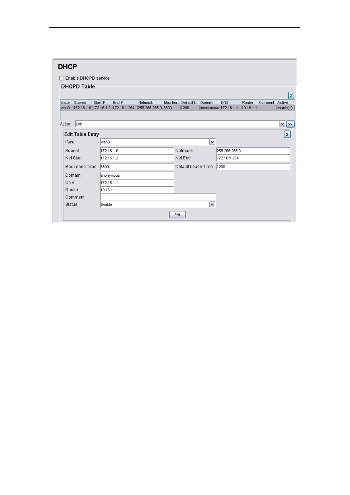
PLANET Mesh Network Manager Guide
Page 93 of 126
5.3.2 Services > DHCP (MAP-3100 only)
The DHCP service offers the Mesh AP a feature to assign dynamic IP Address to all the
clients. The DHCPD Table in this configuration page lists the dynamic IP assignments in the
device.
Parameters (DHCPD Table columns)
1) Iface
• The name of the active interface in the Mesh AP unit.
• Data type: Octet String
2) Subnet
• The subnet address
• Data type: IP Address
3) Netmask
• The netmask corresponding to the subnet of the table entry
• Data type: IP Address
4) Net Start
• The starting IP Address in the subnet for the assignment.
• Data type: IP Address
PLANET Mesh Network Manager Guide
Page 94

PLANET Mesh Network Manager Guide
Page 94 of 126
5) Net End
• The last IP Address in the subnet for the assignment
• Data type: IP Address
6) Max Lease Time
• The maximum duration for the client to retain its current IP Address
• Data type: Integer, in the range of 600 to 864000 seconds
7) Default Lease Time
• The lease time def ined for t he c l ient to ret ai n its c urr en t IP Addr es s . Onc e the
time is up, the IP Address will be released.
• Data type: Integer, in the range of 600 to 864000 seconds
8) Domain
• The domain name for the DHCP Server
• Data type: DNS String
9) DNS
• The IP Address of the DNS server of the subnet
• Data type: IP Address
10) Router
• The router IP Address of the subnet
• Data type: IP Address
11) Comment
• An optional comment for the particular table entry
• Data type: Display String
12) Status
• The status of that particular table entry, either active or inactive
PLANET Mesh Network Manager Guide
Page 95

PLANET Mesh Network Manager Guide
Page 95 of 126
5.3.2.1 Services > MAC Access
The Mac Access featur e of the Mesh AP provides a filter ing method to lim it the acces sing of
the client. User can set the Mac Access Table to deny or inversely, allow the client that
defined with their Mac Address to attach to the network.
Parameters:
1) Enable MAC Access
• A checkbox to enable or disable the MAC Access feature
2) Filter Type
• Define the filter type of the user not listed in t he MAC Ac cess Table, e ither to
allow or deny the client entries to access the network.
Parameters (MAC Access Table)
1) Mac Address
• The Mac Address of the client to be filtered.
• Data type: Mac Address
PLANET Mesh Network Manager Guide
Page 96

PLANET Mesh Network Manager Guide
Page 96 of 126
2) Type
• Define the type of control for th e correspo nding Mac Addr ess, either All ow or
Deny
3) Comment
• An optional comment regarding the client
• Data type: Display String
4) Active
• The status of the table entry, either active or inactive
The Browse Active U sers but to n o pens a lis t tha t s h o ws ev er y ac ti ve user as s oc iating t o the
network. From this table, the administrator may add the desired user into the Mac Access
Table, by using the Update button. Choose the type of accessing from the drop down list.
PLANET Mesh Network Manager Guide
Page 97

PLANET Mesh Network Manager Guide
Page 97 of 126
5.3.2.2 Services > NAT (MAP-3100 only)
The Network Address Translation service enables the clients with IP addresses that are not
globally unique to connect to the network by translating those addresses into a globally
routable IP address space.
Parameters
1) Enable NAT Service
• A checkbox to enable or disable the NAT service
Parameters (NAT Table column)
1) Protocol
• Protocol to use. Choose from UDP, TCP and Both
2) Port
• The port number to forward to.
• Data type: Integer, in the range of 1 to 65535
3) IP Address
• The destination host IP Address
• Data type: IP Address
PLANET Mesh Network Manager Guide
Page 98

PLANET Mesh Network Manager Guide
Page 98 of 126
4) Comment
• An optional comment regarding the selected table entry
• Data type: Display String
5) Active
• The status of the selected table entry, either active or inactive
5.3.2.3 Services > Firewall (MAP-3100 only)
The Firewall service is t h e sec ur it y featur e tha t included in the Mesh A P to lim it c ertain t ype of
traffic. User can define and add a firewall rule through this configuration page.
Parameter
1) Enable Firewall Service
• A checkbox to enable or disable the firewall service
Parameters (Firewall Table columns)
1) Target
• Define the type of the firewall rule, allow or deny the traffic
PLANET Mesh Network Manager Guide
Page 99

PLANET Mesh Network Manager Guide
Page 99 of 126
2) Source Iface
• The source interface of the firewall rule.
• Data type: Octet String
3) Destination Iface
• The destination interface of the firewall rule
• Data type: Octet String
4) Source IP & Mask
• The IP Address and its netmask of the source interface
• Data type: IP Address
5) Destination IP & Mask
• The IP Address and its netmask of the destination interface
• Data type: IP Address
6) Protocol
• The protocol of the rule.
• Data type: Integer, in the range of 0 to 255
7) Start Port & End Port
• The start and end define the range of port.
• Data type: Integer, in the range of -1 to 65535
• Fill the fields with ‘-1’ if the ports is not applicable
8) Comment
• An optional comment regarding the firewall rule
• Data type: Display Stri n g
9) Active
• The status of the firewall rule, either active or inactive
PLANET Mesh Network Manager Guide
Page 100

PLANET Mesh Network Manager Guide
Page 100 of 126
5.3.2.4 Services > Traffic Shaping (MAP-3100 only)
User can set the download and upload speed at the Traffic Shaping configuration page in
order to alter the net work performance. The Traffic Shaping Table def ines the traffic volume
for a port with a specified protocol.
Parameters
1) Enable Traffic Shaping service
• A checkbox to enable or disable the Traffic Shaping service on the Mesh AP
2) WAN Uplink Speed
• Define the upload speed of the WAN interface
• Data type: Integer, in the range of 5 and 100 Mbps
PLANET Mesh Network Manager Guide
 Loading...