

Page 1

User’s Manual of IGS-604HPT-M12
1
Page 2

User’s Manual of IGS-604HPT-M12
Trademarks
Copyright © PLANET Technology Corp. 2016.
Contents are subject to revision without prior notice.
PLANET is a registered trademark of PLANET Technology Corp. All other trademarks belong to their respective owners.
Disclaimer
PLANET Technology does not warrant that the hardware will work properly in all environments and applications, and makes no
warranty and representation, either implied or expressed, with respect to the quality, performance, merchantability, or fitness for
a particular purpose. PLANET has made every effort to ensure that this User's Manual is accurate; PLANET disclaims liability
for any inaccuracies or omissions that may have occurred.
Information in this User's Manual is subject to change without notice and does not represent a commitment on the part of
PLANET. PLANET assumes no responsibility for any inaccuracies that may be contained in this User's Manual. PLANET makes
no commitment to update or keep current the information in this User's Manual, and reserves the right to make improvements to
this User's Manual and/or to the products described in this User's Manual, at any time without notice.
If you find information in this manual that is incorrect, misleading, or incomplete, we would appreciate your comments and
suggestions.
FCC Warning
This equipment has been tested and found to comply with the limits for a Class A digital device, pursuant to Part 15 of the FCC
Rules. These limits are designed to provide reasonable protection against harmful interference when the equipment is operated
in a commercial environment. This equipment generates, uses, and can radiate radio frequency energy and, if not installed and
used in accordance with the Instruction manual, may cause harmful interference to radio communications. Operation of this
equipment in a residential area is likely to cause harmful interference in which case the user will be required to correct the
interference at his own expense.
CE Mark Warning
This is a Class A product. In a domestic environment, this product may cause radio interference, in which case the user may be
required to take adequate measures.
Energy Saving Note of the Device
This power required device does not support Standby mode operation. For energy saving, please remove the power cable to
disconnect the device from the power circuit. In view of saving the energy and reducing the unnecessary power consumption, it
is strongly suggested to remove the power connection for the device if this device is not intended to be active.
WEEE Warning
To avoid the potential effects on the environment and human health as a result of the presence of
hazardous substances in electrical and electronic equipment, end users of electrical and electronic
equipment should understand the meaning of the crossed-out wheeled bin symbol. Do not dispose of
WEEE as unsorted municipal waste and have to collect such WEEE separately.
Revision
User's Manual of PLANET Industrial IP67 Rated 4-Port 10/100/1000T 802.3at PoE + 2-Port 10/100/1000T Managed Ethernet
Switch
FOR MODEL: IGS-604HPT-M12
REVISION: 1.0 (August, 2016)
Part No: EM-IGS-604HPT-M12_v1.0
2
Page 3

User’s Manual of IGS-604HPT-M12
TABLE OF CONTENTS
1. INTRODUCTION..................................................................................................................10
1.1 Package Contents.....................................................................................................................................10
1.2 Product Description.................................................................................................................................. 11
1.3 How to Use This Manual........................................................................................................................... 17
1.4 Product Features....................................................................................................................................... 18
1.5 Product Specifications ............................................................................................................................. 21
2. INSTALLATION ................................................................................................................... 24
2.1 Hardware Description...............................................................................................................................24
2.1.1 Physical Dimensions .......................................................................................................................................... 24
2.1.2 Front Panel ......................................................................................................................................................... 25
2.1.3 LED Indications .................................................................................................................................................. 26
2.1.4 M12 10/100/1000T Connector Pin Assignment .................................................................................................. 28
2.1.5 M12 (8-pin, Male) to RJ45 (8-pin) Straight-through UTP Cable Wiring............................................................... 28
2.1.6 Wiring the DC Power Input ................................................................................................................................. 29
2.2 Installing the Industrial Managed Switch................................................................................................31
2.2.1 Installation Steps ................................................................................................................................................ 31
2.2.2 DIN-rail Mounting................................................................................................................................................ 31
2.2.3 Wall-mount Plate Mounting................................................................................................................................. 34
2.2.4 Recovering Back to Default Configuration .......................................................................................................... 36
3. SWITCH MANAGEMENT.................................................................................................... 37
3.1 Requirements.............................................................................................................................................37
3.2 Management Access Overvi ew................................................................................................................ 38
3.3 CLI Mode Management............................................................................................................................. 39
3.4 Web Management......................................................................................................................................40
3.5 SNMP-based Network Management........................................................................................................ 41
3.6 PLANET Smart Discovery Utility ............................................................................................................. 42
4. WEB CONFIGURATION...................................................................................................... 44
4.1 Main Web page.......................................................................................................................................... 47
4.2 System........................................................................................................................................................ 49
4.2.1 System Information............................................................................................................................................. 50
3
Page 4

User’s Manual of IGS-604HPT-M12
4.2.2 IP Configuration.................................................................................................................................................. 51
4.2.3 IP Status ............................................................................................................................................................. 53
4.2.4 Users Configuration............................................................................................................................................ 54
4.2.5 Privilege Levels .................................................................................................................................................. 57
4.2.6 NTP Configuration .............................................................................................................................................. 59
4.2.7 Time Configuration ............................................................................................................................................. 60
4.2.8 UPnP .................................................................................................................................................................. 61
4.2.9 DHCP Relay ....................................................................................................................................................... 63
4.2.10 DHCP Relay Statistics ...................................................................................................................................... 65
4.2.11 CPU Load ......................................................................................................................................................... 67
4.2.12 System Log....................................................................................................................................................... 68
4.2.13 Detailed Log ..................................................................................................................................................... 69
4.2.14 Remote Syslog ................................................................................................................................................. 70
4.2.15 SMTP Configuration ......................................................................................................................................... 71
4.2.16 Fault Alarm ....................................................................................................................................................... 72
4.2.17 Web Firmware Upgrade.................................................................................................................................... 73
4.2.18 TFTP Firmware Upgrade .................................................................................................................................. 74
4.2.19 Save Startup Config.......................................................................................................................................... 75
4.2.20 Configuration Download ................................................................................................................................... 75
4.2.21 Configuration Upload ........................................................................................................................................ 76
4.2.22 Configuration Activate....................................................................................................................................... 76
4.2.23 Configuration Delete ......................................................................................................................................... 77
4.2.24 Image Select..................................................................................................................................................... 77
4.2.25 Factory Default ................................................................................................................................................. 78
4.2.26 System Reboot ................................................................................................................................................. 79
4.3 Simple Network Management Protocol................................................................................................... 80
4.3.1 SNMP Overview ................................................................................................................................................. 80
4.3.2 SNMP System Configuration .............................................................................................................................. 81
4.3.3 SNMP Trap Configuration................................................................................................................................... 83
4.3.4 SNMP System Information ................................................................................................................................. 85
4.3.5 SNMPv3 Configuration ....................................................................................................................................... 86
4.3.5.1 SNMPv3 Communities ............................................................................................................................. 86
4.3.5.2 SNMPv3 Users......................................................................................................................................... 87
4.3.5.3 SNMPv3 Groups....................................................................................................................................... 88
4.3.5.4 SNMPv3 Views......................................................................................................................................... 89
4.3.5.5 SNMPv3 Access....................................................................................................................................... 90
4.4 Port Management......................................................................................................................................92
4.4.1 Port Configuration............................................................................................................................................... 92
4.4.2 Port Statistics Overview...................................................................................................................................... 94
4.4.3 Port Statistics Detail............................................................................................................................................ 95
4.4.4 Port Mirror........................................................................................................................................................... 97
4.5 Link Aggregation.......................................................................................................................................99
4
Page 5

User’s Manual of IGS-604HPT-M12
4.5.1 Static Aggregation............................................................................................................................................. 101
4.5.2 LACP Configuration.......................................................................................................................................... 102
4.5.3 LACP System Status ........................................................................................................................................ 104
4.5.4 LACP Port Status.............................................................................................................................................. 105
4.5.5 LACP Port Statistics.......................................................................................................................................... 106
4.6 VLAN......................................................................................................................................................... 107
4.6.1 VLAN Overview ................................................................................................................................................ 107
4.6.2 IEEE 802.1Q VLAN .......................................................................................................................................... 108
4.6.3 VLAN Port Configuration ...................................................................................................................................111
4.6.4 VLAN Membership Status..................................................................................................................................117
4.6.5 VLAN Port Status...............................................................................................................................................118
4.6.6 Private VLAN .....................................................................................................................................................119
4.6.7 Port Isolation..................................................................................................................................................... 121
4.6.8 VLAN setting example: ..................................................................................................................................... 123
4.6.8.1 Two Separate 802.1Q VLANs................................................................................................................. 123
4.6.8.2 VLAN Trunking between two 802.1Q aware switches ............................................................................ 126
4.6.8.3 Port Isolate ............................................................................................................................................. 128
4.6.9 MAC-based VLAN ............................................................................................................................................ 130
4.6.10 Protocol-based VLAN ..................................................................................................................................... 131
4.6.11 Protocol-based VLAN Membership................................................................................................................. 134
4.7 Spanning Tree Protocol.......................................................................................................................... 135
4.7.1 Theory .............................................................................................................................................................. 135
4.7.2 STP System Configuration ............................................................................................................................... 141
4.7.3 Bridge Status .................................................................................................................................................... 143
4.7.4 CIST Port Configuration.................................................................................................................................... 144
4.7.5 MSTI Priorities .................................................................................................................................................. 147
4.7.6 MSTI Configuration........................................................................................................................................... 149
4.7.7 MSTI Ports Configuration ................................................................................................................................. 150
4.7.8 Port Status........................................................................................................................................................ 152
4.7.9 Port Statistics.................................................................................................................................................... 153
4.8 Multicast................................................................................................................................................... 154
4.8.1 IGMP Snooping ................................................................................................................................................ 154
4.8.2 Profile Table...................................................................................................................................................... 158
4.8.3 Address Entry ................................................................................................................................................... 159
4.8.4 IGMP Snooping Configuration .......................................................................................................................... 160
4.8.5 IGMP Snooping VLAN Configuration................................................................................................................ 162
4.8.6 IGMP Snooping Port Group Filtering ................................................................................................................ 164
4.8.7 IGMP Snooping Status ..................................................................................................................................... 165
4.8.8 IGMP Group Information................................................................................................................................... 166
4.8.9 IGMPv3 Information.......................................................................................................................................... 167
4.8.10 MLD Snooping Configuration.......................................................................................................................... 168
4.8.11 MLD Snooping VLAN Configuration ............................................................................................................... 169
5
Page 6

User’s Manual of IGS-604HPT-M12
4.8.12 MLD Snooping Port Group Filtering................................................................................................................ 171
4.8.13 MLD Snooping Status..................................................................................................................................... 172
4.8.14 MLD Group Information .................................................................................................................................. 173
4.8.15 MLDv2 Information ......................................................................................................................................... 174
4.8.16 MVR (Multicast VLAN Registration)................................................................................................................ 175
4.8.17 MVR Status..................................................................................................................................................... 178
4.8.18 MVR Groups Information ................................................................................................................................ 179
4.8.19 MVR SFM Information .................................................................................................................................... 180
4.9 Quality of Service....................................................................................................................................181
4.9.1 Understanding QoS .......................................................................................................................................... 181
4.9.2 Port Policing ..................................................................................................................................................... 182
4.9.3 Port Classification............................................................................................................................................. 183
4.9.4 Port Scheduler.................................................................................................................................................. 185
4.9.5 Port Shaping..................................................................................................................................................... 186
4.9.5.1 QoS Egress Port Schedule and Shapers ............................................................................................... 187
4.9.6 Port Tag Remarking.......................................................................................................................................... 189
4.9.6.1 QoS Egress Port Tag Remarking............................................................................................................ 190
4.9.7 Port DSCP ........................................................................................................................................................ 191
4.9.8 DSCP-based QoS ............................................................................................................................................ 193
4.9.9 DSCP Translation............................................................................................................................................. 194
4.9.10 DSCP Classification........................................................................................................................................ 195
4.9.11 QoS Control List ............................................................................................................................................. 196
4.9.11.1 QoS Control Entry Configuration .......................................................................................................... 198
4.9.12 QCL Status ..................................................................................................................................................... 200
4.9.13 Storm Control Configuration ........................................................................................................................... 202
4.9.14 QoS Statistics ................................................................................................................................................. 203
4.9.15 Voice VLAN Configuration .............................................................................................................................. 204
4.9.16 Voice VLAN OUI Table.................................................................................................................................... 206
4.10 Access Control List...............................................................................................................................207
4.10.1 Access Control List Status .............................................................................................................................. 207
4.10.2 Access Control List Configuration ................................................................................................................... 209
4.10.3 ACE Configuration ...........................................................................................................................................211
4.10.4 ACL Ports Configuration ................................................................................................................................. 221
4.10.5 ACL Rate Limiter Configuration ...................................................................................................................... 223
4.11 Authentication........................................................................................................................................224
4.11.1 Understanding IEEE 802.1X Port-based Authentication ................................................................................. 225
4.11.2 Authentication Configuration ........................................................................................................................... 229
4.11.3 Network Access Server Configuration............................................................................................................. 230
4.11.4 Network Access Overview .............................................................................................................................. 241
4.11.5 Network Access Statistics ............................................................................................................................... 242
4.11.6 RADIUS .......................................................................................................................................................... 249
4.11.7 TACACS+ ....................................................................................................................................................... 251
6
Page 7

User’s Manual of IGS-604HPT-M12
4.11.8 RADIUS Overview .......................................................................................................................................... 253
4.11.9 RADIUS Details .............................................................................................................................................. 255
4.11.10 Windows Platform RADIUS Server Configuration......................................................................................... 262
4.11.11 802.1X Client Configuration .......................................................................................................................... 267
4.12 Security .................................................................................................................................................. 270
4.12.1 Port Limit Control............................................................................................................................................ 270
4.12.2 Access Management ...................................................................................................................................... 274
4.12.3 Access Management Statistics ....................................................................................................................... 275
4.12.4 HTTPs ............................................................................................................................................................ 276
4.12.5 SSH ................................................................................................................................................................ 277
4.12.6 Port Security Status........................................................................................................................................ 277
4.12.7 Port Security Detail......................................................................................................................................... 280
4.12.8 DHCP Snooping ............................................................................................................................................. 281
4.12.9 Snooping Table ............................................................................................................................................... 282
4.12.10 IP Source Guard Configuration..................................................................................................................... 283
4.12.11 IP Source Guard Static Table ........................................................................................................................ 284
4.12.12 Dynamic IP Source Guard Table................................................................................................................... 285
4.12.13 ARP Inspection ............................................................................................................................................. 286
4.12.14 ARP Inspection Static Table.......................................................................................................................... 288
4.12.15 Dynamic ARP Inspection Table ..................................................................................................................... 289
4.13 MAC Address Table............................................................................................................................... 291
4.13.1 MAC Table Configuration ................................................................................................................................ 291
4.13.2 MAC Address Table Status ............................................................................................................................. 293
4.14 LLDP.......................................................................................................................................................295
4.14.1 Link Layer Discovery Protocol ........................................................................................................................ 295
4.14.2 LLDP Configuration ........................................................................................................................................ 295
4.14.3 LLDP MED Configuration ............................................................................................................................... 298
4.14.4 LLDP-MED Neighbor ...................................................................................................................................... 305
4.14.5 Neighbor ......................................................................................................................................................... 309
4.14.6 Port Statistics.................................................................................................................................................. 310
4.15 Network Diagnostics............................................................................................................................. 312
4.15.1 Ping ................................................................................................................................................................ 313
4.15.2 IPv6 Ping ........................................................................................................................................................ 314
4.15.3 Remote IP Ping Test ....................................................................................................................................... 315
4.15.4 Cable Diagnostics........................................................................................................................................... 316
4.16 Power over Ethernet ............................................................................................................................. 318
4.16.1 Power over Ethernet Powered Device............................................................................................................ 319
4.16.2 System Configuration ..................................................................................................................................... 320
4.16.3 Power Over Ethernet Configuration................................................................................................................ 321
4.16.4 Port Sequential ............................................................................................................................................... 322
4.16.5 Port Configuration........................................................................................................................................... 323
7
Page 8

User’s Manual of IGS-604HPT-M12
4.16.6 PoE Status...................................................................................................................................................... 325
4.16.7 PoE Schedule................................................................................................................................................. 327
4.16.8 PoE Alive Check Configuration....................................................................................................................... 329
4.16.9 LLDP PoE Neighbours.................................................................................................................................... 331
4.17 Loop Protection.....................................................................................................................................332
4.17.1 Configuration .................................................................................................................................................. 332
4.17.2 Loop Protection Status ................................................................................................................................... 333
4.18 RMON......................................................................................................................................................335
4.18.1 RMON Alarm Configuration ............................................................................................................................ 335
4.18.2 RMON Alarm Status ....................................................................................................................................... 337
4.18.3 RMON Event Configuration ............................................................................................................................ 338
4.18.4 RMON Event Status ....................................................................................................................................... 339
4.18.5 RMON History Configuration .......................................................................................................................... 340
4.18.6 RMON History Status ..................................................................................................................................... 341
4.18.7 RMON Statistics Configuration ....................................................................................................................... 342
4.18.8 RMON Statistics Status................................................................................................................................... 343
4.19 PTP..........................................................................................................................................................345
4.19.1 PTP Configuration .......................................................................................................................................... 345
4.19.2 PTP Status...................................................................................................................................................... 349
4.20 Ring.........................................................................................................................................................351
4.20.1 MEP Configuration.......................................................................................................................................... 352
4.20.2 Detailed MEP Configuration ........................................................................................................................... 353
4.20.3 Ethernet Ring Protocol Switch ........................................................................................................................ 357
4.20.4 Ethernet Ring Protocol Switch Configuration.................................................................................................. 359
4.20.5 Ring Wizard .................................................................................................................................................... 362
4.20.6 Ring Wizard Example: .................................................................................................................................... 363
5. SWITCH OPERATION....................................................................................................... 366
5.1 Address Table..........................................................................................................................................366
5.2 Learning ................................................................................................................................................... 366
5.3 Forwarding & Filtering............................................................................................................................ 366
5.4 Store-and-Forward..................................................................................................................................366
5.5 Auto-Negotiation ..................................................................................................................................... 367
6. TROUBLESHOOTING....................................................................................................... 368
APPENDIX A: Networking Connection............................................................................... 369
A.1 Switch's Data RJ45 Pin Assignments - 1000Mbps, 1000BASE-T....................................................... 369
8
Page 9

User’s Manual of IGS-604HPT-M12
A.2 10/100Mbps, 10/100BASE-TX.................................................................................................................369
APPENDIX B : GLOSSARY.................................................................................................. 371
9
Page 10

User’s Manual of IGS-604HPT-M12
1. INTRODUCTION
Thank you for purchasing PLANET Industrial L2+ Managed Ethernet Switch. “Industrial Managed Switch” is used as an
alternative name in this user’s manual.
1.1 Package Contents
Open the box of the Industrial Managed Switch and carefully unpack it. The box should contain the following items:
The Industrial Managed Switch x 1
Quick Installation Guide x 1
1.2m M12 Power Cable x 1
2m M12-to-RJ45 UTP Cable x 1
M12 Female Dust Cap x 6
M12 Power Waterproof Cap x 1
DIN-rail Kit x 1
Wall-mount Kit x 1
If any of these are missing or damaged, please contact your dealer immediately; if possible, retain the carton including the
original packing material, and use them again to repack the product in case there is a need to return it to us for repair.
10
Page 11
User’s Manual of IGS-604HPT-M12
1.2 Product Description
Suitable for Industrial Environment
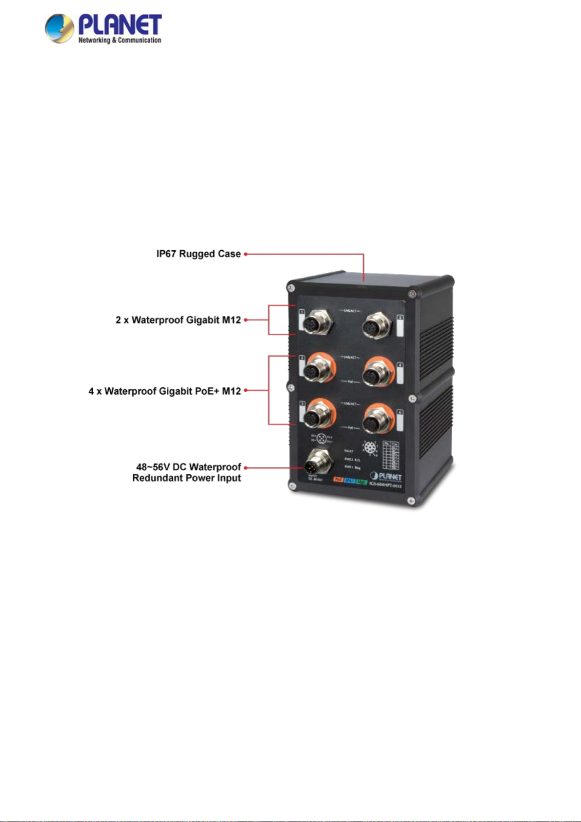
PLANET IGS-604HPT-M12, an Industrial Managed Ethernet Switch, comes with an IP67-rated industrial case, 4-port
10/100/1000T 802.3at PoE, 2-port 10/100/1000T, and static Layer 3 routing, providing a high level of immunity against
electromagnetic interference and heavy electrical surges which are usually found on plant floors or in curb-side traffic control
cabinets. The IGS-604HPT-M12 can be easily mounted on a DIN rail or wall taking up less space. Each of the four Gigabit
PoE+ ports provides 36 watts of power, which means a total power budget of up to 144 watts can be utilized simultaneously
without considering the different types of PoE applications being employed. It also provides a quick, safe and cost-effective
Power over Ethernet network solution to IP security surveillance for small businesses and enterprises.
Waterproof and Dustproof M12 Ethernet Connector
The IGS-604HPT-M12 is equipped with a 6-port 10/100/1000BASE-T auto-negotiation waterproof and dustproof M12 connector
with 4-port IEEE 802.3at PoE+ (Port 3 to Port 6); each PoE port provides 36-watt PoE output. The M12 connector provides tight
and strong connection and guarantees stable Ethernet operation performance under high vibration and shock environment and
ensures it comes with the industrial protection rating of IP67 capable of withstanding humidity, dirt, dust, shock, vibrations, heat
and cold.
11
Page 12

User’s Manual of IGS-604HPT-M12
Environmentally Hardened Design
The IGS-604HPT-M12 is able to protect itself from dust and water ingress, and to operate under the temperature range from -40
to 75 degrees C. All these features ensure the highest level of reliability for mission-critical applications in any difficult
environment.
Dual Power Input for High Availability Network System
The IGS-604HPT-M12 features a strong dual power input system (Dual 48V~56V DC) incorporated into customer’s automation
network to enhance system reliability and uptime. For example, when DC Power 1 fails to work, the hardware failover function
will be activated automatically to keep powering the IGS-604HPT-M12 via DC Power 2 alternatively without any loss of
operation.
Centralized Power Management for Gigabit Ethernet PoE Networking
To fulfill the needs of higher power required PoE network applications with Gigabit speed transmission, the IGS-604HPT-M12
features high-performance Gigabit IEEE 802.3at PoE+ (up to 36 watts) on all ports. It perfectly meets the power requirements of
PoE VoIP phone, PoE Wireless AP and all kinds of PoE IP cameras such as IR, PTZ, speed dome cameras and even box type
IP cameras with a built-in fan and heater for high power consumption. The IGS-604HPT-M12’s PoE capabilities also help to
reduce deployment costs for network devices as a result of freeing from restrictions of power outlet locations. Power and data
switching are integrated into one unit, delivered over a single cable and managed centrally. It thus eliminates cost for additional
AC wiring and reduces installation time.
12
Page 13
User’s Manual of IGS-604HPT-M12
Built-in Unique PoE Functions for Surveillance Management
As a managed PoE Switch for surveillance network, the IGS-604HPT-M12 features the following intelligent PoE management
functions:
PD Alive Check
Scheduled Power Recycling
SMTP/SNMP Trap Event Alert
PoE Schedule
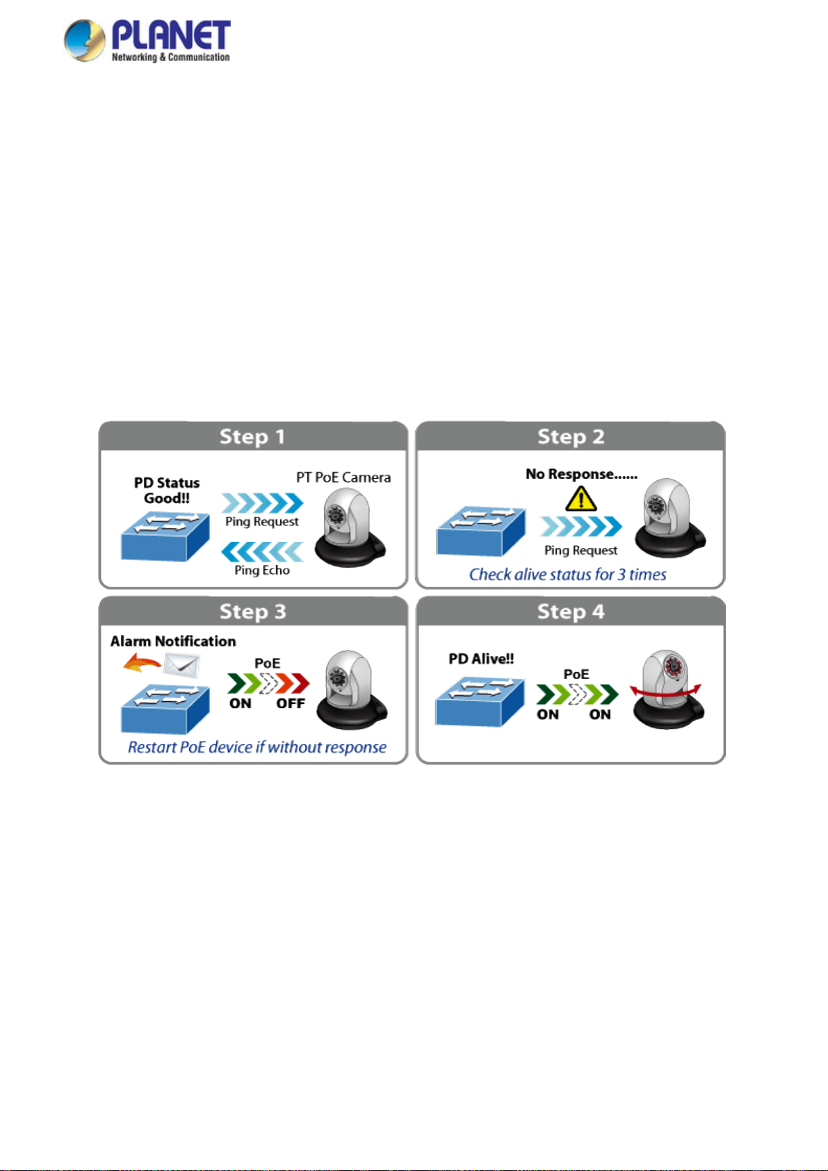
Intelligent Powered Device Alive Check
The IGS-604HPT-M12 can be configured to monitor a connected PD (Powered Device) status in real time via ping action. Once
the PD stops working and it is without response, the IGS-604HPT-M12 will resume the PoE port power and bring the PD back to
work. It will greatly enhance the network reliability through the PoE port resetting the PD’s power source, thus reducing
administrator management burden.
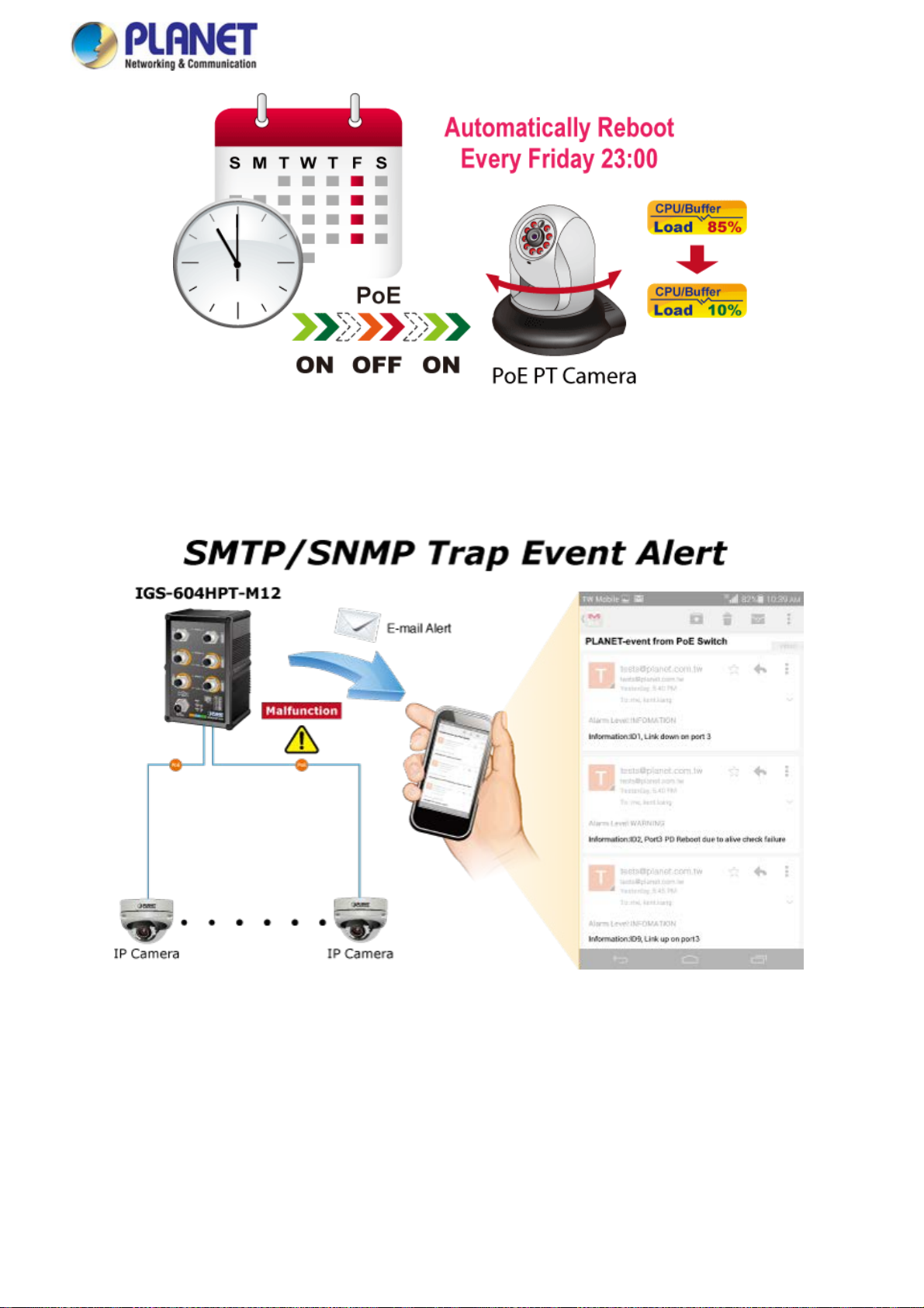
Scheduled Power Recycling
The IGS-604HPT-M12 allows each of the connected PDs to reboot at a specified time each week. Therefore, it will reduce the
chance of PD crash resulting from buffer overflow.
13
Page 14
User’s Manual of IGS-604HPT-M12
SMTP/SNMP Trap Event Alert
Though most NVR or camera management software offers SMTP email alert function, the IGS-604HPT-M12 further provides
event alert function to help to diagnose the abnormal device owing to whether or not there is a break of the network connection,
loss of PoE power or the rebooting response by the PD Alive Check process.
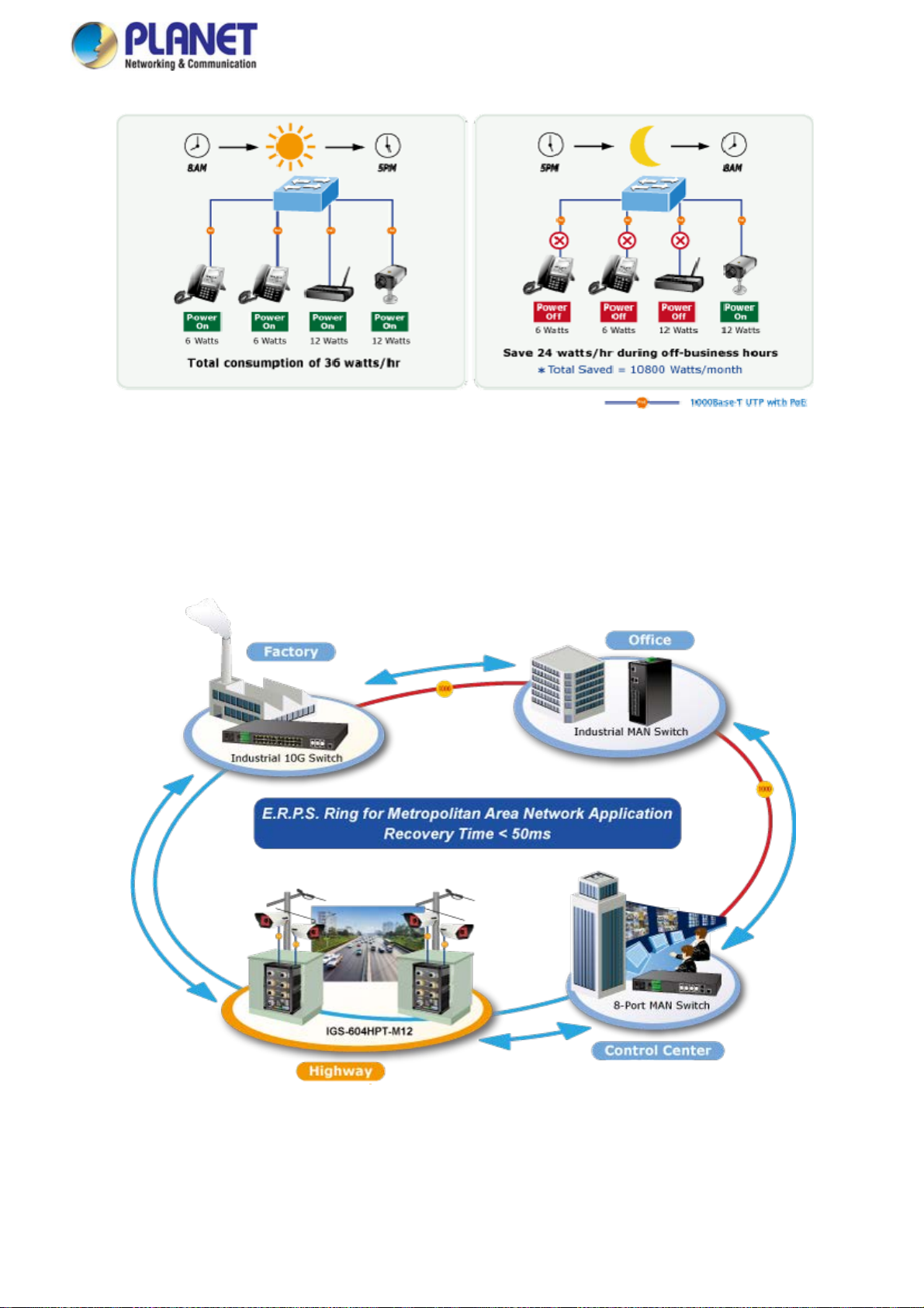
PoE Schedule for Energy Saving
Besides being used for IP surveillance, the IGS-604HPT-M12 is certainly applicable to build any PoE network including VoIP
and wireless LAN. Under the trend of energy saving worldwide and contributing to the environmental protection on the Earth,
the IGS-604HPT-M12 can effectively control the power supply besides its capability of giving high watts power. The “PoE
schedule” function helps you to enable or disable PoE power feeding for each PoE port during specified time intervals and it is a
powerful function to help SMBs and enterprises save energy and budget.
14
Page 15
User’s Manual of IGS-604HPT-M12
Redundant Ring, Fast Recovery for Critical Network Applications
The IGS-604HPT-M12 supports redundant ring technology and features strong, rapid self-recovery capability to prevent
interruptions and external intrusions. It incorporates advanced ITU-T G.8032 ERPS (Ethernet Ring Protection Switching)
technology, Spanning Tree Protocol (802.1s MSTP), and redundant power input system into customer’s industrial automation
network to enhance system reliability and uptime in harsh factory environments. In a certain, simple Ring network, the recovery
time of data link can be as fast as 20ms.
IPv6/IPv4 Dual Stack
Supporting both IPv6 and IPv4 protocols, the IGS-604HPT-M12 helps data centers, campuses, telecoms, and more to
experience the IPv6 era with the lowest investment as its network facilities need not be replaced or overhauled if the IPv6 FTTx
edge network is set up.
15
Page 16
User’s Manual of IGS-604HPT-M12
Laye
r 3 IPv4 and IPv6 VLAN Routing for Secure and Flexible Management
The IGS-604HPT-M12 not only provides ultra high transmission performance, and excellent layer 2 and layer 4 technologies,
but also layer 3 IPv4/IPv6 VLAN routing feature which allows to crossover different VLANs and different IP addresses for the
purpose of having a highly-secure, flexibly-managed and simple networking application.
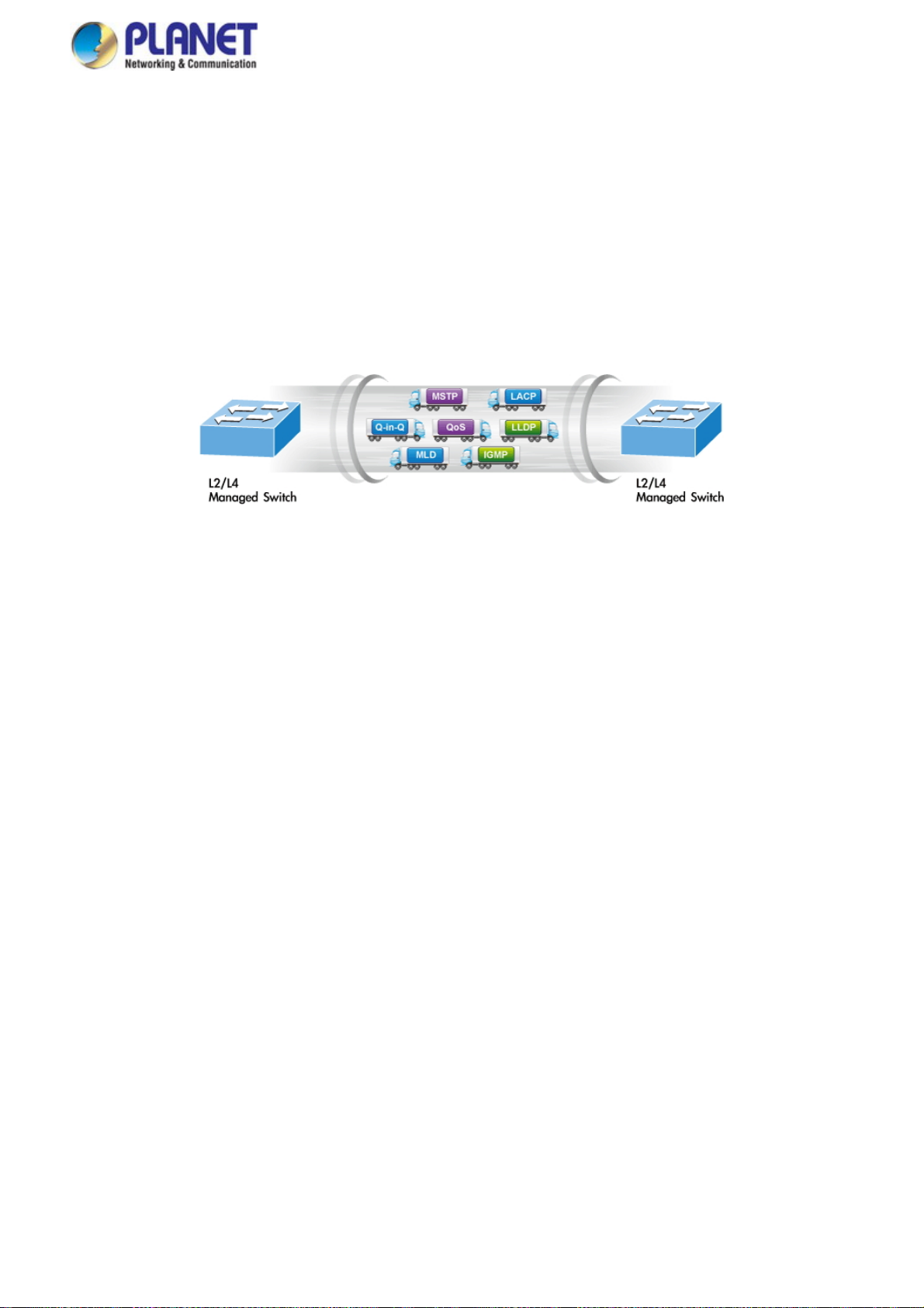
Robust Layer 2 Features
The IGS-604HPT-M12 can be programmed for advanced switch management functions such as dynamic port link aggregation,
Q-in-Q VLAN, private VLAN, Multiple Spanning Tree Protocol (MSTP), Layer 2 to Layer 4 QoS, bandwidth control and
IGMP/MLD Snooping. Via the link aggregation of supporting ports, the IGS-604HPT-M12 allows the operation of a high-speed
trunk to combine with multiple fiber ports and supports fail-over as well.
Powerful Security
The IGS-604HPT-M12 offers a comprehensive layer 2 to layer 4 Access Control List (ACL) for enforcing security to the edge.
It can be used to restrict network access by denying packets based on source and destination IP address, TCP/UDP ports or
defined typical network applications. Its protection mechanism also comprises 80 2.1X Port-based and MAC-based user, and
device authentication. With the private VLAN function, communication between edge ports can be prevented to ensure user
privacy. The IGS-604HPT-M12 also provides DHCP Snooping, IP Source Guard and Dynamic ARP Inspection functions to
prevent IP snooping from attack and discard ARP packets with invalid MAC address. The network administrators can now
construct highly-secure corporate networks with considerably less time and effort than before.
Excellent Traffic Control
The IGS-604HPT-M12 is loaded with powerful traffic management and QoS features to enhance connection services by
telecoms and ISPs. The QoS feature includes wire-speed Layer 4 traffic classifiers and bandwidth limit that are particularly
useful for multi-tenant units, multi-business units, Telco and network service providers’ applications. It also empowers the
industrial environment to take full advantage of the limited network resources and guarantees the best performance in VoIP and
video conferencing transmission.
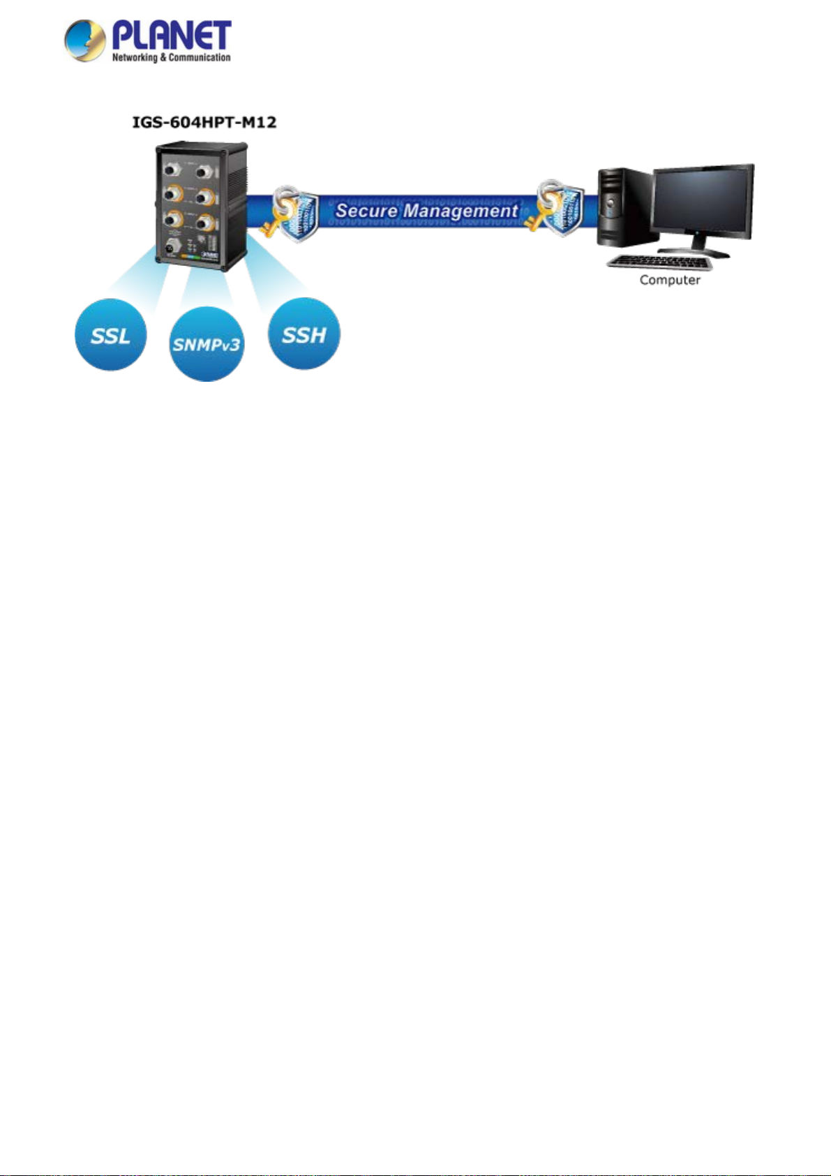
Efficient and Secure Management
With built-in Web-based management interface, the IGS-604HPT-M12 L2+ Managed Switch offers an easy-to-use,
platform-independent management and configuration facility which includes Web and SNMP management interfaces. The
SNMP can be managed via any management software based on the standard of SNMP Protocol. For reducing product learning
time, it offers Cisco-like command via Telnet and customer does not need to learn new console command. Moreover, it also
offers secure remote management by supporting SSH, SSL and SNMP v3 connections which encrypt the packet content at
each session.
16
Page 17
User’s Manual of IGS-604HPT-M12
1.3 How to Use This Manual
This User’s Manual is structured as follows:
Section 2, INSTALLATION
The section explains the functions of the Industrial Managed Switch and how to physically install the Industrial
Managed Switch.
Section 3, SWITCH MANAGEMENT
The section contains the information about the software function of the Industrial Managed Switch.
Section 4, WEB CONFIGURATION
The section explains how to manage the Industrial Managed Switch by Web interface.
Section 5, SWITCH OPERATION
The chapter explains how to do the switch operation of the Industrial Managed Switch.
Section 6, TROUBLESHOOTING
The chapter explains how to do troubleshooting of the Industrial Managed Switch.
Appendix A
The section contains cable information of the Industrial Managed Switch.
Appendix B
The section contains glossary information of the Industrial Managed Switch.
17
Page 18

User’s Manual of IGS-604HPT-M12
1.4 Product Features
Physical Port
6-port 10/100/1000BASE-T waterproof and dustproof M12 connectors with 4-port IEEE 802.3at/af Power over
Ethernet Injector function
Hardware Conformance
Complies with IEEE 802.3at Power over Ethernet Plus end-span PSE
Complies with IEEE 802.3af Power over Ethernet end-span PSE
Up to 4 ports of IEEE 802.3af/802.3at devices powered
Supports PoE Power up to 36 watts for each PoE port
Auto detects powered device (PD)
Circuit protection prevents power interference between ports
Remote power feeding up to 100 meters
PoE Management
Total PoE power budget control
Per port PoE function enable/disable
PoE Port Power feeding priority
Per PoE port power limitation
PD classification detection
PD alive check
PoE schedule
PD scheduled power recycling
Hardware Conformance
IP67-rated aluminum case
Redundant power design
48 to 56V DC, redundant power with polarity reverse protect function
Active-active redundant power failure protection
Backup of catastrophic power failure on one supply
Fault tolerance and resilience
DIN-rail and wall-mount design
Supports 6000V DC Ethernet ESD protection
-40 to 75 degrees C operating temperature
Layer 3 IP Routing Features
Supports maximum 32 static routes and route summarization
Layer 2 Features
Prevents packet loss with back pressure (half-duplex) and IEEE 802.3x pause frame flow control (full-duplex)
High performance of Store-and-Forward architecture, and runt/CRC filtering that eliminates erroneous packets to
optimize the network bandwidth
Storm control support
Broadcast/Multicast/Unicast
Supports VLAN
IEEE 802.1Q tagged VLAN
18
Page 19

Up to 255 VLANs groups, out of 4095 VLAN IDs
Provides Bridging (VLAN Q-in-Q) support (IEEE 802.1ad)
Private VLAN Edge (PVE)
Protocol-based VLAN
MAC-based VLAN
IP subnet-based VLAN
Voice VLAN
Supports Spanning Tree Protocol
IEEE 802.1D Spanning Tree Protocol (STP)
IEEE 802.1w Rapid Spanning Tree Protocol (RSTP)
IEEE 802.1s Multiple Spanning Tree Protocol (MSTP), spanning tree by VLAN
BPDU Guard
Supports Link Aggregation
802.3ad Link Aggregation Control Protocol (LACP)
Cisco ether-channel (static trunk)
Maximum 3 trunk groups, with 2 ports for each trunk
Up to 4Gbps bandwidth (full duplex mode)
Provides port mirror (many-to-1)
Port mirroring monitors the incoming or outgoing traffic on a particular port
Loop protection to avoid broadcast loops
Supports E.R.P.S. (Ethernet Ring Protection Switching)
IEEE 1588 and synchronous Ethernet network timing
User’s Manual of IGS-604HPT-M12
Quality of Service
Ingress shaper and egress rate limit per port bandwidth control
8 priority queues on all switch ports
Traffic classification
- IEEE 802.1p CoS
- ToS/DSCP/IP precedence of IPv4/IPv6 packets
- IP TCP/UDP port number
- Typical network application
Strict priority and Weighted Round Robin (WRR) CoS policies
Traffic-policing policies on the switch port
DSCP remarking
Multicast
Supports IGMP snooping v1, v2 and v3
Supports MLD snooping v1 and v2
Querier mode support
IGMP snooping port filtering
MLD snooping port filtering
MVR (Multicast VLAN Registration)
19
Page 20

User’s Manual of IGS-604HPT-M12
Security
Authentication
- IEEE 802.1x port-based/MAC-based network access authentication
- IEEE 802.1x authentication with guest VLAN
- Built-in RADIUS client to cooperate with the RADIUS servers
- RADIUS/TACACS+ users access authentication
Access Control List
- IP-based Access Control List (ACL)
- MAC-based Access Control List (ACL)
Source MAC/IP address binding
DHCP Snooping to filter distrusted DHCP messages
Dynamic ARP Inspection discards ARP packets with invalid MAC address to IP address binding
IP Source Guard prevents IP spoofing attacks
IP address access management to prevent unauthorized intruder
Management
IPv4 and IPv6 dual stack management
Switch Management Interfaces
- Telnet command line interface
- Web switch management
- SNMP v1, v2c, and v3 switch management
- SSH/SSL secure access
IPv6 address/NTP management
Built-in Trivial File Transfer Protocol (TFTP) client
BOOTP and DHCP for IP address assignment
System Maintenance
- Firmware upload/download via HTTP/TFTP
- Reset button for system reboot or reset to factory default
- Dual images
DHCP relay and option 82
User privilege levels control
NTP (Network Time Protocol)
Link Layer Discovery Protocol (LLDP) and LLDP-MED
Network diagnostic
- Cable diagnostic technology provides the mechanism to detect and report potential cabling issues
- ICMPv6/ICMPv4 remote ping
SMTP/Syslog remote alarm
Four RMON groups (history, statistics, alarms and events)
SNMP trap for interface link up and link down notification
System Log
PLANET Smart Discovery Utility for deployment management
20
Page 21
1.5 Product Specifications
Product IGS-604HPT-M12
Hardware Specifications
Copper Ports
PoE Injector Port
Power Connector
Switch Architecture
Switch Fabric
Throughput
Address Table
Shared Data Buffer
Flow Control
Jumbo Frame
Dimensions (W x D x H)
Weight
Enclosure
Installation
LED
6 x M12, 8-pin A-Coded female connector, 10/100/1000BASE-T
auto-MDI/MDI-X ports
4 ports with 802.3at/af PoE injector function (Port-3 to Port-6)
1 x M12, 5-pin A-Coded male connector
Store-and-Forward
12Gbps/non-blocking
8.9Mpps@64bytes
8K entries, automatic source address learning and aging
4M bits
IEEE 802.3x pause frame for full-duplex
Back pressure for half-duplex
9K bytes
103 x 68.2 x 163 mm
1069g
IP67 aluminum case
Wall-mount kit and DIN rail kit
System:
PWR1 (Green), PWR2 (Green), Fault (Red)
Ring (Green), R.O. (Green)
10/100/1000T RJ45 Interfaces (Port 1 to Port 2):
LNK/ACT (Green)
10/100/1000T RJ45 Interfaces (Port 3 to Port 6):
LNK/ACT (Green)
PoE-in-Use (Orange)
User’s Manual of IGS-604HPT-M12
Power Consumption
Power Requirements
ESD Protection
Power over Ethernet
PoE Standard IEEE 802.3af/802.3at PoE/PSE
PoE Power Supply Type End-span
PoE Power Output
Power Pin Assignment 1/2(+), 3/6(-)
PoE Power Budget
PD @ 7 watts 4 units
PoE Ability
Layer 2 Management Functions
PD @ 15.4 watts 4 units
PD @ 30.8 watts 4 units
Max. 165.3 watts/563.7 BTU
Dual 48~56V DC (>53V DC for PoE+ output recommended)
6KV DC
IEEE 802.3af Standard
- Per port 48V~53V DC (depending on the power supply), max. 15.4
watts
IEEE 802.3at Standard
- Per port 53V~56V DC (depending on the power supply), max. 36 watts
144 watts max. (depending on power input)
21
Page 22

Port Configuration
Port Status
Port Mirroring
VLAN
Link Aggregation
Spanning Tree Protocol
QoS
IGMP Snooping
MLD Snooping
Access Control List
Bandwidth Control
Layer 3 Functions
User’s Manual of IGS-604HPT-M12
Port disable/enable
Auto-negotiation 10/100/1000Mbps full and half duplex mode selection
Flow control disable/enable
Display each port’s speed duplex mode, link status, flow control status,
auto-negotiation status, trunk status
TX/RX/Both
Many-to-1 monitor
802.1Q tagged based VLAN
Q-in-Q tunneling
Private VLAN Edge (PVE)
MAC-based VLAN
Protocol-based VLAN
Voice VLAN
IP Subnet-based VLAN
MVR (Multicast VLAN registration)
Up to 255 VLAN groups, out of 4095 VLAN IDs
IEEE 802.3ad LACP/static trunk
3 groups with 2 ports per trunk
IEEE 802.1D Spanning Tree Protocol (STP)
IEEE 802.1w Rapid Spanning Tree Protocol (RSTP)
IEEE 802.1s Multiple Spanning Tree Protocol (MSTP)
Traffic classification based, strict priority and WRR
8-level priority for switching:
- Port number
- 802.1p priority
- 802.1Q VLAN tagging
- DSCP/ToS field in IP packet
IGMP (v1/v2/v3) snooping, up to 255 multicast groups
IGMP querier mode support
MLD (v1/v2) snooping, up to 255 multicast groups
MLD querier mode support
IP-based ACL/MAC-based ACL
Up to 256 entries
Per port bandwidth control
Ingress: 100Kbps~1000Mbps
Egress: 100Kbps~1000Mbps
IP Interfaces Max. 8 VLAN interfaces
Routing Table Max. 32 routing entries
Routing Protocols
Management
Basic Management Interfaces Telnet; Web browser; SNMP v1, v2c
Secure Management Interfaces SSH/SSL, SNMP v3
SNMP MIBs
IPv4 software static routing
IPv6 software static routing
RFC 1213 MIB-II
RFC 1493 Bridge MIB
RFC 1643 Ethernet MIB
22
RFC 2863 IF-MIB
RFC 2933 IGMP-STD-MIB
RFC 3411 SNMP-Frameworks-MIB
Page 23

RFC 2863 Interface MIB
RFC 2665 Ether-Like MIB
RFC 2819 RMON MIB
(Groups 1, 2, 3 and 9)
RFC 2737 Entity MIB
RFC 2618 RADIUS Client
MIB
Standards Conformance
Regulatory Compliance FCC Part 15 Class A, CE
IEC60068-2-32 (free fall)
Stability Testing
Railway Traffic *EN50155
Standards Compliance
Environment
Operating
Storage
Standard Accessories
Packet Contents
IEC60068-2-27 (shock)
IEC60068-2-6 (vibration)
IEEE 802.3 10BASE-T
IEEE 802.3u 100BASE-TX
IEEE 802.3ab Gigabit
1000T
IEEE 802.3x flow control
and back pressure
IEEE 802.3ad port trunk
with LACP
IEEE 802.1D Spanning
Tree Protocol
IEEE 802.1w Rapid
Spanning Tree Protocol
IEEE 802.1s Multiple
Spanning Tree Protocol
IEEE 802.1p Class of
Service
IEEE 802.1Q VLAN
tagging
IEEE 802.1X Port
Authentication Network
Control
Temperature: -40 ~ 75 degrees C
Relative Humidity: 5 ~ 95% (non-condensing)
Temperature: -40 ~ 80 degrees C
Relative Humidity: 5 ~ 95% (non-condensing)
1 x 8-pin A-code M12-to-RJ45 UTP cable, 2m
1 x M12 5-pin A-coded female connector power cable, 1.2m
1 x Wall-mount kit
1 x DIN-rail kit
1 x Quick Installation Guide
6 x M12 Female Dust Cap
1 x M12 Power Waterproof Cap
User’s Manual of IGS-604HPT-M12
RFC 4292 IP Forward MIB
RFC 4293 IP MIB
RFC 4836 MAU-MIB
IEEE 802.1X PAE
LLDP
Power over Ethernet MIB
IEEE 802.1ab LLDP
IEEE 802.3af Power over Ethernet
IEEE 802.3at Power over Ethernet Plus
IEEE 802.3az EEE (Energy Efficient
Ethernet)
RFC 768 UDP
RFC 793 TFTP
RFC 791 IP
RFC 792 ICMP
RFC 2068 HTTP
RFC 1112 IGMP v1
RFC 2236 IGMP v2
RFC 3376 IGMP v3
RFC 2710 MLD v1
RFC 3810 MLD v2
ITU-T G.8032 ERPS (Ethernet Ring
Protection Switching)
* The certificate will be obtained in December this year.
23
Page 24
User’s Manual of IGS-604HPT-M12
2. INSTALLATION
2.1 Hardware Description
This section describes the hardware features of Industrial Managed Switch. For easier management and control of the Industrial
Managed Switch, familiarize yourself with its display indicators and ports. Front panel illustrations in this chapter display the unit
LED indicators. Before connecting any network device to the Industrial Managed Switch, read this chapter carefully.
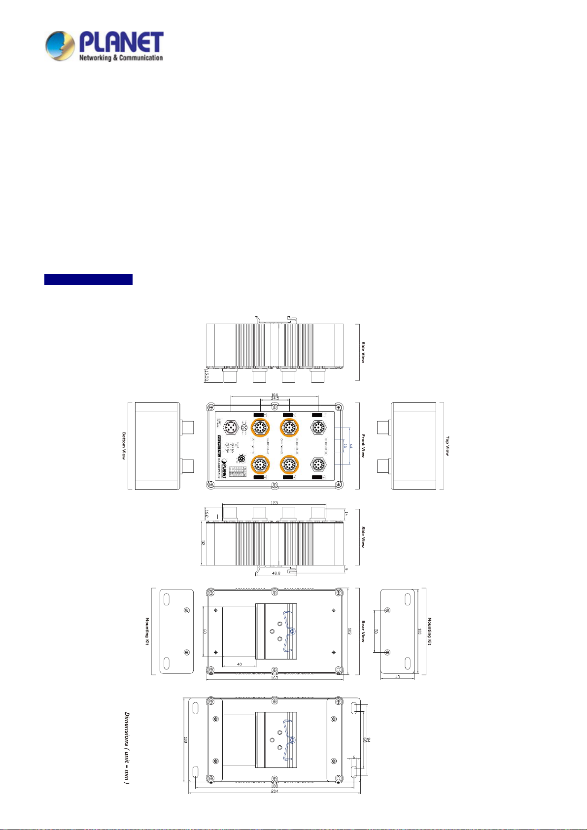
2.1.1 Physical Dimensions
IGS-604HPT-M12
Dimensions (W x D x H) : 103 x 68.3 x 163mm
24
Page 25

User’s Manual of IGS-604HPT-M12
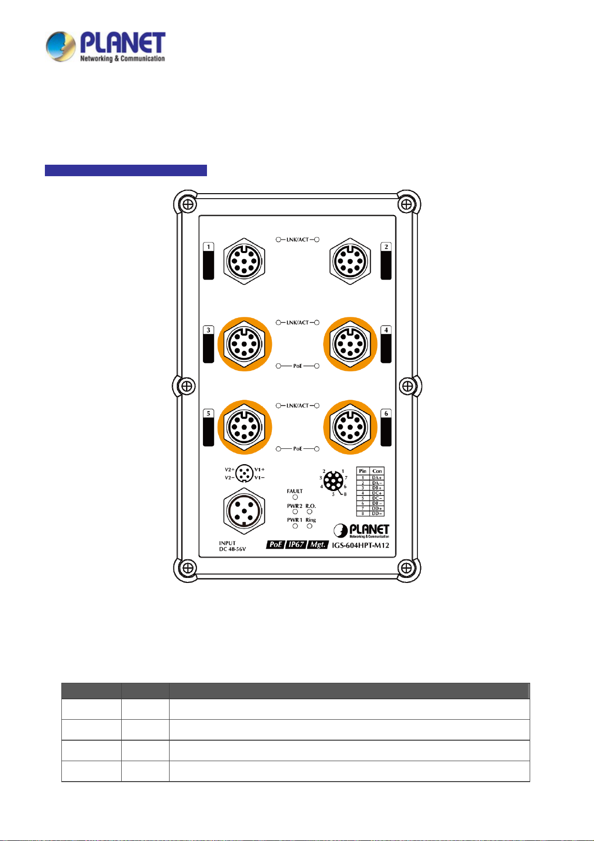
2.1.2 Front Panel
The front panel provides a simple interface monitoring the Managed Switch. Figure 2-1 shows the front panel of the Managed
Switch.
IGS-604HPT-M12 Front Panel
Figure 2-1: IGS-604HPT-M12 Switch Front Panel
■ Gigabit TP Interface
10/100/1000BASE-T M12 copper: Up to 100 meters.
■ M12 DC Power Connector
The front panel of the Managed Switch has an M12 DC power connector, which accepts DC power input voltage from -48V
to -56V DC.
25
Page 26
User’s Manual of IGS-604HPT-M12
2.1.3 LED Indications
The front panel LEDs indicate instant status of power and system status, fan status, port links, PoE-in-use and data activity; they
help monitor and troubleshoot when needed. Figure 2-2 shows the LED indications of the Managed Switch.
IGS-604HPT-M12 LED Indication
■ LED Definiti on
■ System
LED Color Function
PWR1 Green Lights to indicate DC power input 1 has power.
PWR2 Green Lights to indicate DC power input 2 has power.
Fault Red Lights to indicate that Switch DC has failed.
Ring Green Lights to indicate that the ERPS Ring has been created successfully.
Figure 2-2: IGS-604HPT-M12 LED on Front Panel
26
Page 27

User’s Manual of IGS-604HPT-M12
R.O. Green
Lights to indicate that Ring state is in idle mode.
Blinks to indicate that the Ring state is in protected mode.
■ Per 10/100/1000BASE-T Port (port 1~2)
LED Color Function
Lights
1000
Green
LNK/ACT
Blinks
Indicating the port is running in 10/100/1000Mbps speed and
successfully established.
Indicating that the switch is actively sending or receiving data over that
port.
■ Per 10/100/1000BASE-T PoE+ Port (port 3~6)
LED Color Function
Lights
LNK/ACT Green
Blinks
Indicating the port is running in 10/100/1000Mbps speed and
successfully established.
Indicating that the switch is actively sending or receiving data over that
port.
PoE-in-Use Orange
Lights
Off
To indicate the port is providing 45~53V DC in-line power.
To indicate the connected device is not a PoE powered device (PD).
27
Page 28
User’s Manual of IGS-604HPT-M12
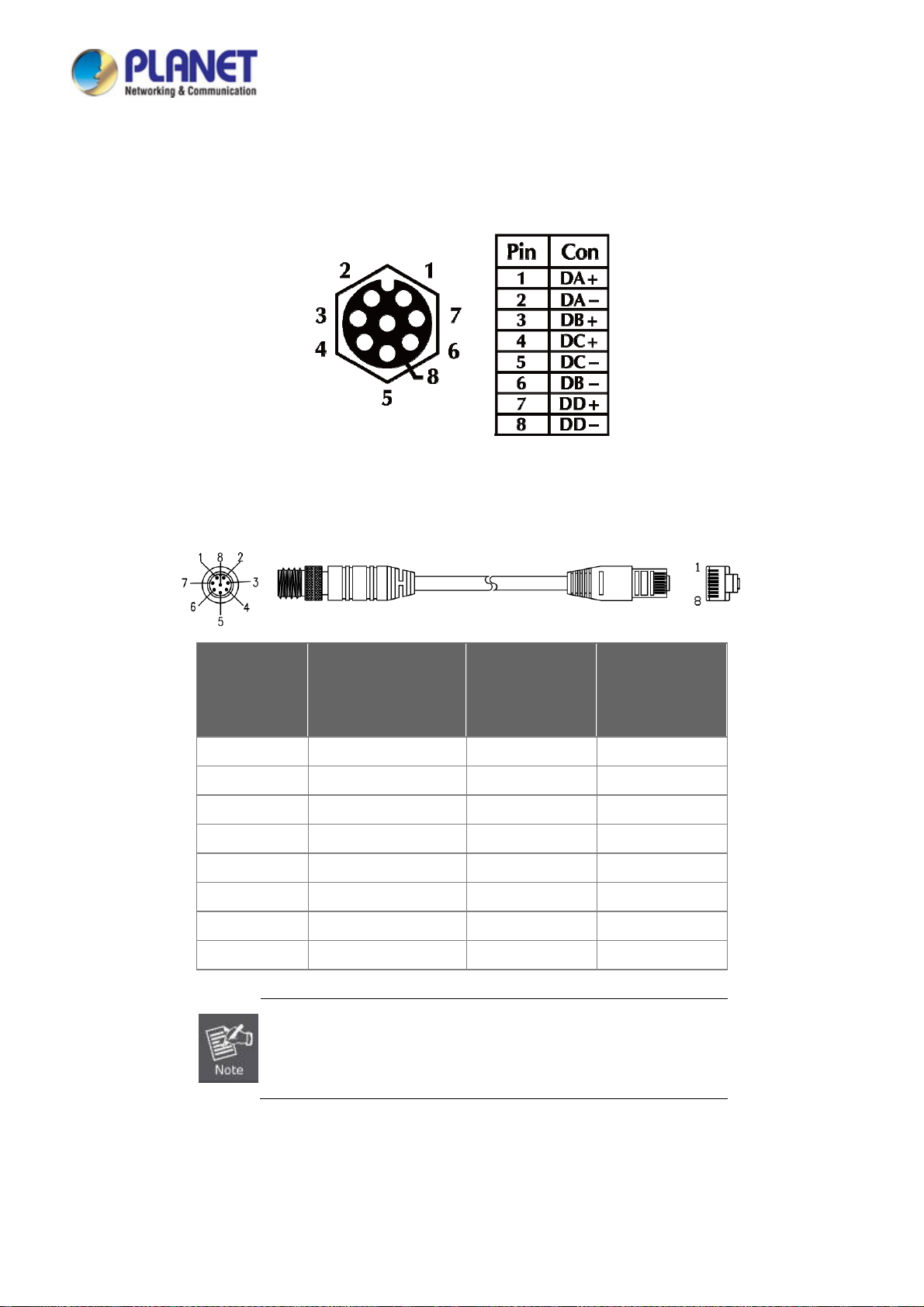
2.1.4 M12 10/100/1000T Connector Pin Assignment
The Industrial Managed Switch front panel provides six 10/100/1000BASE-T Ethernet ports in the form of M12 8-pin A-coded
female connector. These ports are designed for Ethernet equipment connection through Cat5/5e UTP cables. The M12 input
interface pinout is shown below:
8-pin M12 Female 10/100/1000T Connector Pin Assignment
2.1.5 M12 (8-pin, Male) to RJ45 (8-pin) Straight-through UTP Cable Wiring
M12 A-code
Male Connector
Pin No.
1 BI_DA+ white/orange 1
2 BI_DA- orange 2
3 BI_DB+ white/green 3
4 BI_DC+ blue 4
5 BI_DC- white/blue 5
6 BI_DB- green 6
7 BI_DD+ white/brown 7
8 BI_DD- brown 8
1000BASE-T Signal ID
MDI
T568B Color
RJ45 connector
Pin No.
As each Ethernet port of the Industrial Managed Switch is running in auto
negotiation mode, make sure the Ethernet ports of the corresponding
Ethernet devices are also running in auto negotiation mode; otherwise, the
Ethernet performance will be poor.
28
Page 29
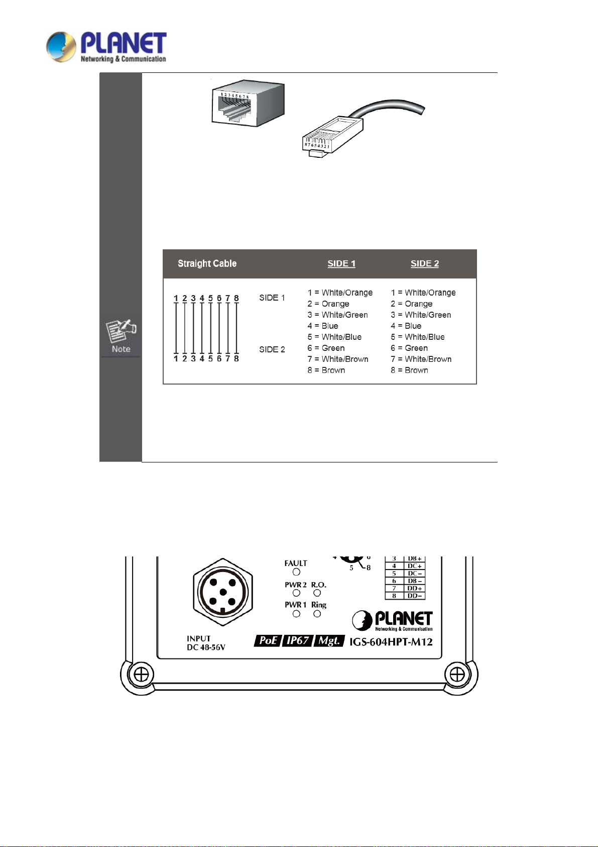
User’s Manual of IGS-604HPT-M12
The standard RJ45 receptacle/connector
There are 8 wires on a standard UTP/STP cable and each wire is color-coded. The
following shows the pin allocation and colors of straight-through cable connection:
Please make sure your waterproof RJ45 cables are with the same pin assignment and
colors as the above picture before deploying the cables into your network.
2.1.6 Wiring the DC Power Input
The front panel of the Industrial Managed Switch provides one M12 A-coded 5-pin male connector for DC power input.
Please use the power cable with the M12 A-coded 5-pin female connector from the Industrial Managed Switch package for DC
power input. The M12 DC power cable pin assignment is shown below:
29
Page 30
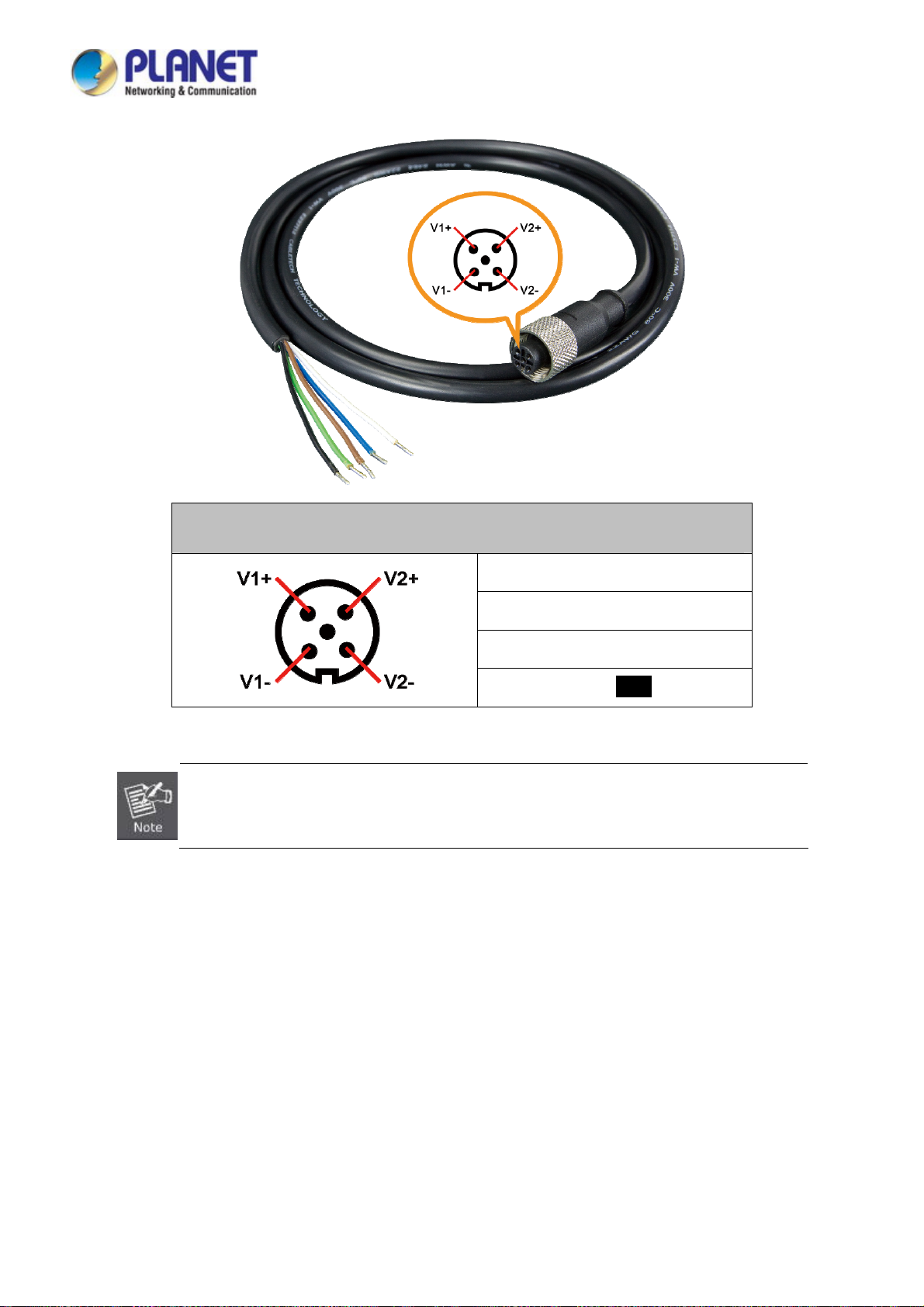
User’s Manual of IGS-604HPT-M12
M12 DC power cable pin assignment & wire code
V1 positive (+) pin = black cable
V1 negative (-) pin = brown cable
V2 positive (+) pin = blue cable
Make sure you connect the correct power pin to your DC power source.
1. The wire gauge for the power cable should be in the range of 12 ~ 24 AWG.
2. The DC power input range is 48 ~ 56V DC.
V2 negative (-) pin = white cable
30
Page 31

User’s Manual of IGS-604HPT-M12
2.2 Installing the Industrial Managed Switch
This section describes how to install your Industrial Managed Switch and make connections to the Industrial Managed Switch.
Please read the following topics and perform the procedures in the order being presented. To install your Industrial Managed
Switch on a desktop or shelf, simply complete the following steps.
In this paragraph, we will describe how to install the Industrial Managed Switch and the installation points attended to it.
2.2.1 Installation Steps
1. Unpack the Industrial Managed Switch
2. Check if the DIN-rail is screwed on the Industrial Managed Switch or not. If the DIN-rail is not screwed on the
Industrial Managed Switch, please refer to DIN-rail Mounting section for DIN-rail installation. If users want to
wall-mount the Industrial Managed Switch, please refer to the W all-mount Plate Mounting section for wall-mount plate
installation.
3. To hang the Industrial Managed Switch on the DIN-rail track or wall.
4. Power on the Industrial Managed Switch. Please refer to the Wiring the Power Inputs section for the information
about how to wire the power. The power LED on the Industrial Managed Switch will light up. Please refer to the LED
Indicators section for indication of LED lights.
5. Prepare the M12 cable for Ethernet connection.
6. Insert one side of M12 cable into the Industrial Managed Switch Ethernet port while the other side to the network
device’s Ethernet port (RJ45 port), e.g., Switch PC or Server. The UTP port (RJ45) LED on the Industrial Managed
Switch will light up when the cable is connected with the network device. Please refer to the LED Indicators section for
LED indication.
Make sure that the connected network devices support MDI/MDI-X. If it does not support,
use the crossover Category 5 cable.
7. When all connections are set and all LED lights show normal, the installation is completed.
2.2.2 DIN-rail Mounting
This section describes how to install the Industrial Managed Switch. There are two methods to install the Industrial
Managed Switch -- DIN-rail mounting and wall-mount plate mounting. Please read the following topics and perform the
procedures in the order being presented.
31
Page 32

Follow all the DIN-rail installation steps as shown in the example.
Step 1: Screw the DIN-rail on the Industrial Managed Switch.
User’s Manual of IGS-604HPT-M12
Step 2: Lightly slide the DIN-rail into the track.
tep 3: Check whether the DIN-rail is tightly on the track.
S
Please refer to the following procedures to remove the Industrial Managed Switch from the track.
32
Page 33

Step 4: Lightly remove the DIN-rail from the track.
User’s Manual of IGS-604HPT-M12
33
Page 34

User’s Manual of IGS-604HPT-M12
2.2.3 Wall-mount Plate Mounting
To install the Industrial Managed Switch on the wall, please follow the instructions below.
Follow all the DIN-rail installation steps as shown in the example.
Step 1: Remove the DIN-rail from the Industrial Managed Switch. Use the screwdriver to loosen the screws to remove the
DIN-rail.
Step 2: Place the wall-mount plate on the rear panel of the Industrial Managed Switch.
Step 3: Use the screwdriver to screw the wall-mount plate on the Industrial Managed Switch.
34
Page 35

User’s Manual of IGS-604HPT-M12
Step 4: Use the hook holes at the corners of the wall mount plate to hang the Industrial Managed Switch on the wall.
Step 5: To remove the wall-mount plate, reverse the steps above.
35
Page 36

User’s Manual of IGS-604HPT-M12
2.2.4 Recovering Back to Default Configuration
IP address has been changed or admin password has been forgotten –
1. Power off the Industrial Managed Switch and remove all the existing connections.
2. Use the M12 cable to connect to port 1 and port 2 in the loop topology as shown below:
3. Power on the Industrial Managed Switch and 6 LNK/ACT LEDs will be lit.
4. Resetting Industrial Managed Switch to the factory default is done when 6 LNK/ACT LEDs are lit again.
5. Remove the M12 cable from port 1 and port 2.
6. Reset the Industrial Managed Switch to Factory Default configuration. The Industrial Managed Switch will then reboot and
load the default settings as shown below:
Default Username: admin
Default Password: admin
Default IP Address: 192.168.0.100
Default Subnet Mask: 255.255.255.0
Default Gateway: 192.168.0.254
36
Page 37

User’s Manual of IGS-604HPT-M12
3. SWITCH MANAGEMENT
This chapter explains the methods that you can use to configure management access to the Industrial Managed Switch. It
describes the types of management applications and the communication and management protocols that deliver data between
your management device (workstation or personal computer) and the system. It also contains information about port connection
options.
This chapter covers the following topics:
Requirements
Management Access Overview
Remote Telnet Access
Web Management Access
SNMP Access
Standards, Protocols, and Related Reading
3.1 Requirements
Workstation running Windows XP/2003, Vista, Windows 7/8/10, MAC OS X, Linux, Fedora, Ubuntu or other
platform is compatible with TCP/IP protocols.
Workstation is installed with Ethernet NIC (Network Interface Card)
Ethernet Port
Network cables -- Use standard network (UTP) cables with RJ45 connectors.
The above workstation is installed with Web browser and JAVA runtime environment Plug-in
It is recommended to use Internet Explore 8.0 or above to access Industrial Managed Switch.
37
Page 38

User’s Manual of IGS-604HPT-M12
3.2 Management Access Overview
The Industrial Managed Switch gives you the flexibility to access and manage it using any or all of the following methods:
Remote Telnet Interface
Web browser Interface
An external SNMP-based network management application
The remote Telnet and Web browser interfaces are embedded in the Industrial Managed Switch software and are available for
immediate use. Each of these management methods has their own advantages. Table 3-1 compares the three management
methods.
Method Advantages Disadvantages
Remote
Telnet
Web Browser
SNMP Agent
Text-based
Telnet functionality built into Windows
XP/2003, Vista, Windows 7 operating
systems
Can be accessed from any location
Ideal for configuring the switch remotely
Compatible with all popular browsers
Can be accessed from any location
Most visually appealing
Communicates with switch functions at
the MIB level
Based on open standards
Table 3-1: Management Methods Comparison
Security can be compromised (hackers need
only know the IP address)
Security can be compromised (hackers need
only know the IP address and subnet mask)
May encounter lag times on poor connections
Requires SNMP manager software
Least visually appealing of all three methods
Some settings require calculations
Security can be compromised (hackers need
only know the community name)
38
Page 39

User’s Manual of IGS-604HPT-M12
3.3 CLI Mode Management
Remote telnet is an IP-based protocol and console port is for user to operate the Industrial Managed Switch locally only;
however, their operations are the same.
The command line user interface is for performing system administration, such as displaying statistics or changing option
settings. When this method is used, you can access the Industrial Managed Switch remote telnet interface from personal
computer, or workstation in the same Ethernet environment as long as you know the current IP address of the Industrial
Managed Switch.
You can change these settings, if desired, after you log on. This management method is often preferred because you can
remain connected and monitor the system during system reboots. Also, certain error messages are sent to the serial port,
regardless of the interface through which the associated action was initiated. A Macintosh or PC attachment can use any
terminal-emulation program for connecting to the terminal serial port. A workstation attachment under UNIX can use an emulator
Remote Telnet
In Windows system, you may click “Start” and then choose “Acessories”and “Command Prompt”. Please input “telnet
192.168.0.100” and press “enter’ from your keyboard. You will see the following screen appears as Figure 3-1 shows.
F
igure 3-1: Remote Telnet Interface Main Screen of Industrial Managed Switch
39
Page 40

User’s Manual of IGS-604HPT-M12
3.4 Web Management
The Industrial Managed Switch offers management features that allow users to manage the Industrial Managed Switch from
anywhere on the network through a standard browser such as Microsoft Internet Explorer. After you set up your IP address for
the Industrial Managed Switch, you can access the Industrial Managed Switch’s Web interface applications directly in your
Web browser by entering the IP address of the Industrial Managed Switch.
Figure 3-2: Web Management
You can then use your Web browser to list and manage the Industrial Managed Switch configuration parameters from one
central location; the Web Management requires Microsoft Internet Explorer 8.0 or later.
Figure 3-3: Web Main Screen of Industrial Managed Switch
40
Page 41

User’s Manual of IGS-604HPT-M12
3.5 SNMP-based Network Management
You can use an external SNMP-based application to configure and manage the Industrial Managed Switch, such as SNMP
Network Manager, HP Openview Network Node Management (NNM) or What’s Up Gold. This management method requires
the SNMP agent on the Industrial Managed Switch and the SNMP Network Management Station to use the same community
string. This management method, in fact, uses two community strings: the get community string and the set community
string.
If the SNMP Network Management Station only knows the set community string, it can read and write to the MIBs. However, if it
only knows the get community string, it can only read MIBs. The default gets and sets community strings for the Industrial
Managed Switch are public.
Figure 3-4: SNMP Management
41
Page 42
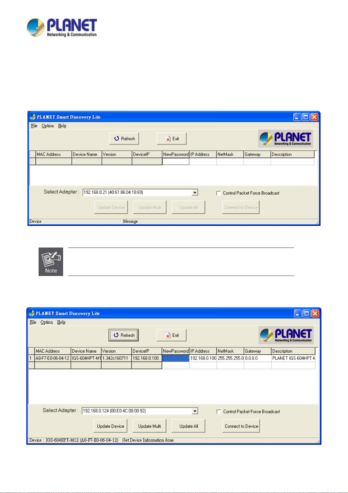
User’s Manual of IGS-604HPT-M12
3.6 PLANET Smart Discovery Utility
To easily list the Industrial Managed Switch in your Ethernet environment, the Planet Smart Discovery Utility from user’s
manual CD-ROM is an ideal solution. The following install instructions guide you to running the Planet Smart Discovery Utility.
1. Open the Planet Smart Discovery Utility in administrator PC.
2. Run this utility and the following screen appears.
Figure 3-5: Planet Smart Discovery Utility Screen
If there are two LAN cards or above in the same administrator PC, choose a different LAN card
by using the “Select Adapter” tool.
3. Press the “Refresh” button for the currently connected devices in the discovery list as the screen is shown as follows.
Figure 3-6: Planet Smart Discovery Utility Screen
42
Page 43

User’s Manual of IGS-604HPT-M12
1. This utility shows all the necessary information from the devices, such as MAC Address, Device Name, firmware version
and Device IP Subnet address. A new password, IP Subnet address and description can be assigned to the devices.
2. After setup is completed, press the “Update Device”, “Update Multi” or “Up date A ll” button to take effect. The meanings
of the 3 buttons above are shown below:
Update Device: Use the current setting on one single device.
Update Multi: Use thecurrent setting on choose multi-devices.
Update All: Use the current setting on whole devices in the list.
The same functions mentioned above also can be found in “Option” tools bar.
3. To click the “Control Packet Force Broadcast” function, it allows new setting value to be assigned to the Web Smart
Switch under a different IP subnet address.
4. Press the “Connect to Device” button and then the Web login screen appears in Figure 3-6.
5. Press the “Exit” button to shut down Planet Smart Discovery Utility.
43
Page 44
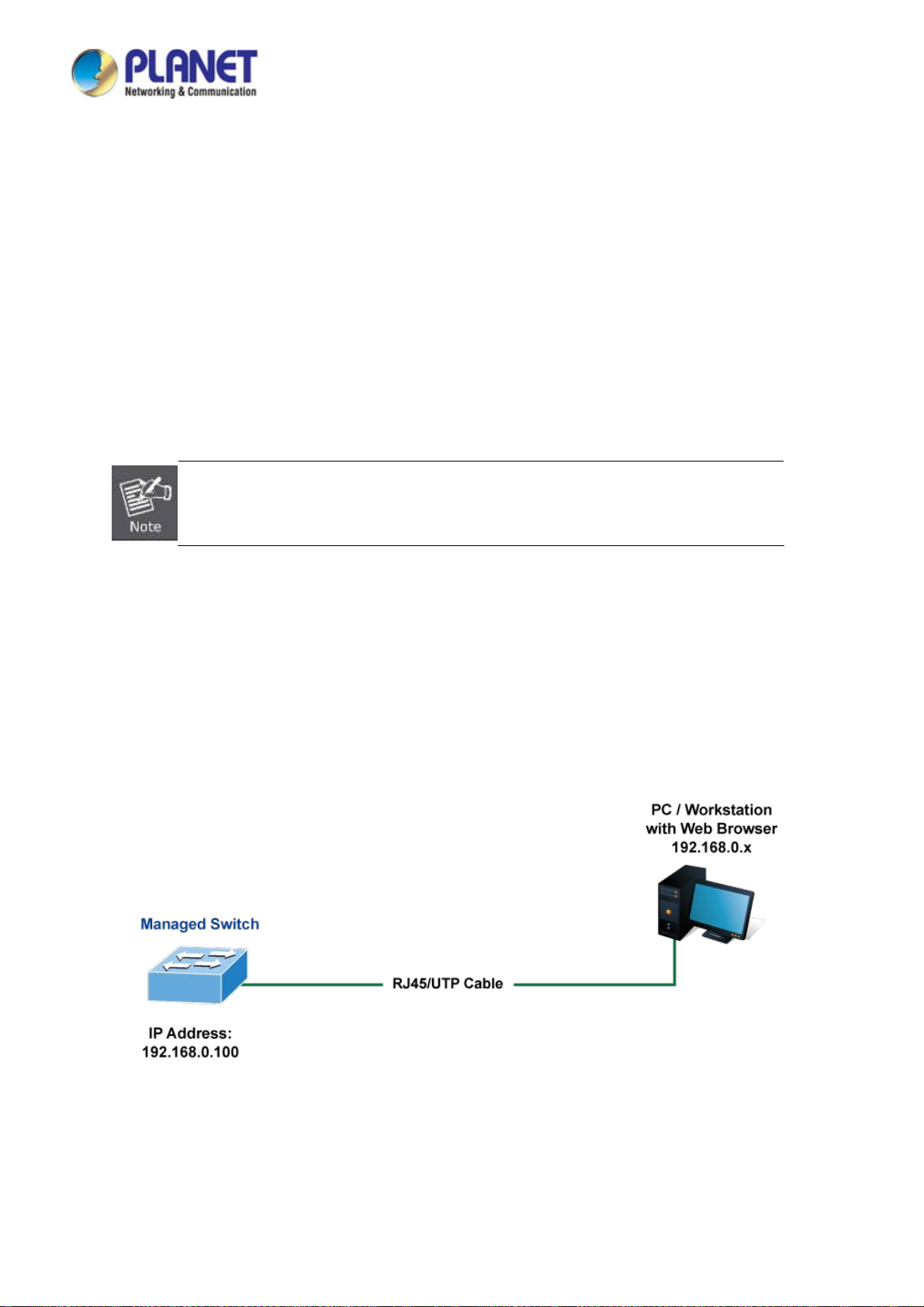
User’s Manual of IGS-604HPT-M12
4. WEB CONFIGURATION
This section introduces the configuration and functions of the Web-based management.
About Web-based Management
The Industrial Managed Switch offers management features that allow users to manage the Industrial Managed Switch from
anywhere on the network through a standard browser such as Microsoft Internet Explorer.
The Web-based Management supports Internet Explorer 8.0. It is based on Java Applets with an aim to reducing network
bandwidth consumption, enhancing access speed and presenting an easy viewing screen.
By default, IE7.0 or later version does not allow Java Applets to open sockets. The user has to
explicitly modify the browser setting to enable Java Applets to use network ports.
The Industrial Managed Switch can be configured through an Ethernet connection, making sure the manager PC must be set
on same the IP subnet address with the Industrial Managed Switch.
For example, the default IP address of the Industrial Managed Switch is 192.168.0.100, then the manager PC should be set
at 192.168.0.x (where x is a number between 1 and 254, except 100), and the default subnet mask is 255.255.255.0.
If you have changed the default IP address of the Industrial Managed Switch to 192.168.1.1 with subnet mask 255.255.255.0
via console, then the manager PC should be set at 192.168.1.x (where x is a number between 2 and 254) to do the related
configuration on manager PC.
Figure 4-1-1: Web Management
Logging on the Industrial Managed Switch
1. Use Internet Explorer 7.0 or above Web browser. Enter the factory-default IP address to access the Web interface. The
factory-default IP address is as follows:
44
Page 45

User’s Manual of IGS-604HPT-M12
http://192.168.0.100
2. When the following login screen appears, please enter the default username "admin" with password “admin” (or the
username/password you have changed via console) to login the main screen of Industrial Managed Switch. The login
screen in Figure 4-1-2 appears.
Figure 4-1-2: Login Screen
Default User name: admin
Default Password: admin
After entering the username and password, the main screen appears as Figure 4-1-3.
Figure 4-1-3: Default Main Page
45
Page 46

User’s Manual of IGS-604HPT-M12
Now, you can use the Web management interface to continue the switch management or manage the Industrial Managed
Switch by Web interface. The Switch Menu on the left of the web page lets you access all the commands and statistics the
Industrial Managed Switch provides.
1. It is recommended to use Internet Explore 8.0 or above to access Industrial Managed Switch.
2. The changed IP address takes effect immediately after clicking on the Save button. From now
on, you need to use the new IP address to access the Internet.
3. For security reason, please change and memorize the new password after this first setup.
4. Only accept command in lowercase letter.
46
Page 47
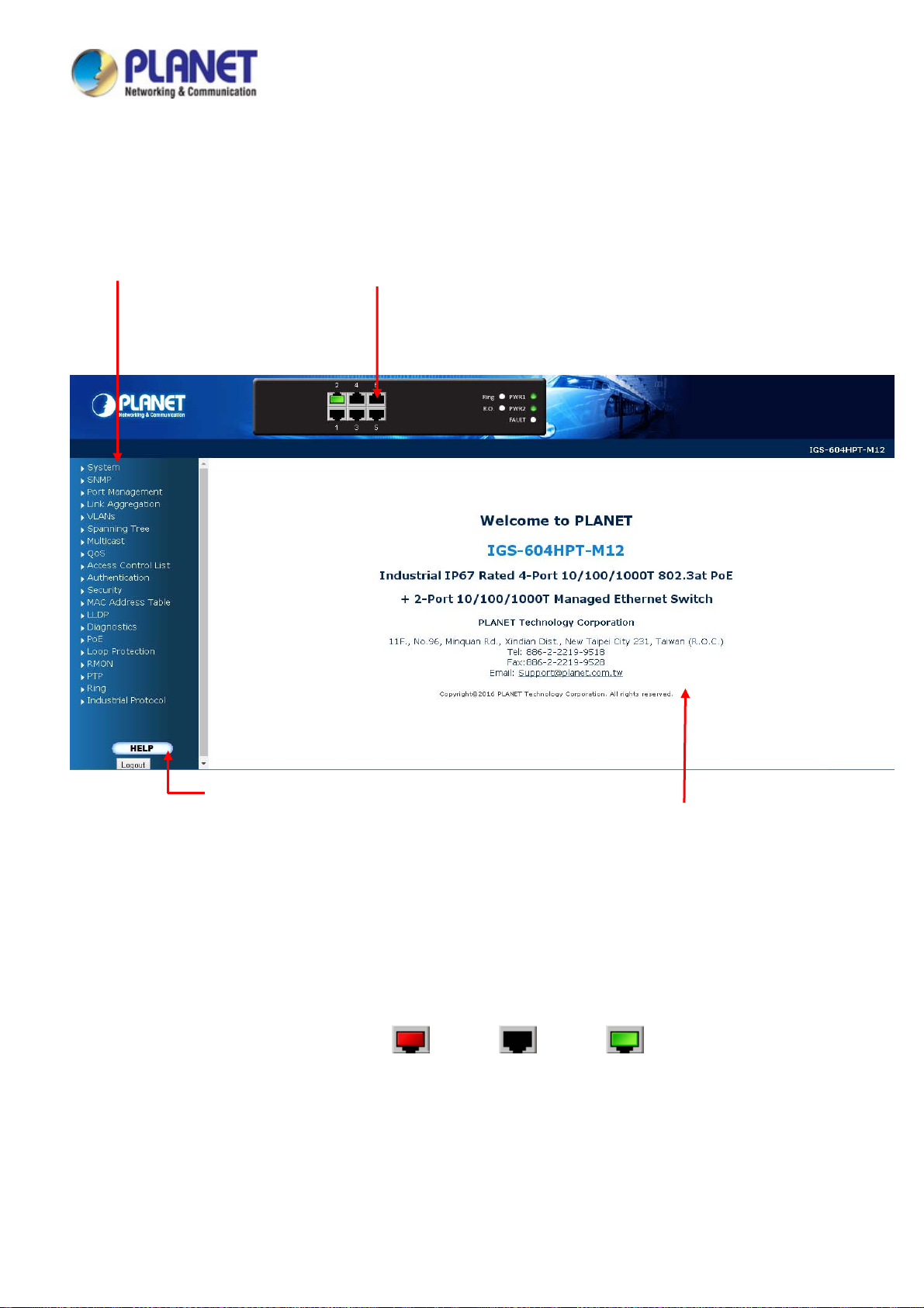
User’s Manual of IGS-604HPT-M12
4.1 Main Web page
The Industrial Managed Switch provides a Web-based browser interface for configuring and managing it. This interface allows
you to access the Industrial Managed Switch using the Web browser of your choice. This chapter describes how to use the
Industrial Managed Switch’s Web browser interface to configure and manage it.
Main Functions Menu
Copper Port Link Status
Help Button
el Display
Pan
The web agent displays an image of the Industrial Managed Switch’s ports. The Mode can be set to display different
information for the ports, including Link up or Link down. Clicking on the image of a port opens the Port Statistics page.
The port states are illustrated as follows:
State Disabled Down Link
RJ45 Ports
igure 4-1-4: Main Page
F
Main Screen
Main Screen
47
Page 48

User’s Manual of IGS-604HPT-M12
Main Menu
Using the onboard web agent, you can define system parameters, manage and control the Industrial Managed Switch, and all
its ports, or monitor network conditions. Via the Web-Management, the administrator can set up the Industrial Managed
Switch by selecting the functions those listed in the Main Function. The screen in Figure 4-1-5 appears.
Figure 4-1-5: Industrial Managed Switch Main Functions Menu
48
Page 49

User’s Manual of IGS-604HPT-M12
4.2 System
Use the System menu items to display and configure basic administrative details of the Industrial Managed Switch. Under
System the following topics are provided to configure and view the system information.
■ System Information The Managed Switch system information is provided here.
■ IP Configuration Configures the Managed Switch with IPv4/IPv6 interface and IP routes on
this p
age.
■ IP Status
■ Users Configuration
This page displays the status of the IP protocol layer. The status is defined
by the IP interfaces, the IP routes and the neighbour cache (ARP cache)
status.
This page provides an overview of the current users. Currently the only way
to login as another user on the web server is to close and reopen the
browser.
■ Privilege Levels
■ NTP Configuration Configure NTP server on this page.
■ Time Configure time parameter on this page.
■ UPnP Configure UPnP on this page.
■ DHCP Relay Configure DHCP Relay on this page.
■ DHCP Relay Statistics This page provides statistics for DHCP relay.
■ CPU Load This page displays the CPU load, using an SVG graph.
■ System Log The Managed Switch system log information is provided here.
■ Detailed Log The Managed Switch system detailed log information is provided here.
■ Remo te Syslog Configure remote syslog on this page.
■ SMTP Configuration Configuration SMTP parameters on this page.
■ Fault Alarm Configuration fault alarm on this page.
■ Web Firmware Upgrade This page facilitates an update of the firmware controlling the Managed
■ TFTP Firmware Upgrade Upgrade the firmware via TFTP server
■ Save Startup Config
This page provides an overview of the privilege levels.
Switch.
This copies running-config to startup-config, thereby ensuring that the
currently active configuration will be used at the next reboot.
■ Configuration Download
■ Configuration Upload
■ Configuration Activate
■ Configuration Delete
■ Imag e Select
■ Factory Default
■ System Reboot You can restart the Managed Switch on this page. After restarting, the
You can download the files on the switch.
You can upload the files to the switch.
You can activate the configuration file present on the switch.
You can delete the writable files which are stored in flash.
Configuration active or alternate firmware on this page.
You can reset the configuration of the Managed Switch on this page. Only
the IP configuration is retained.
Managed Switch will boot normally.
49
Page 50
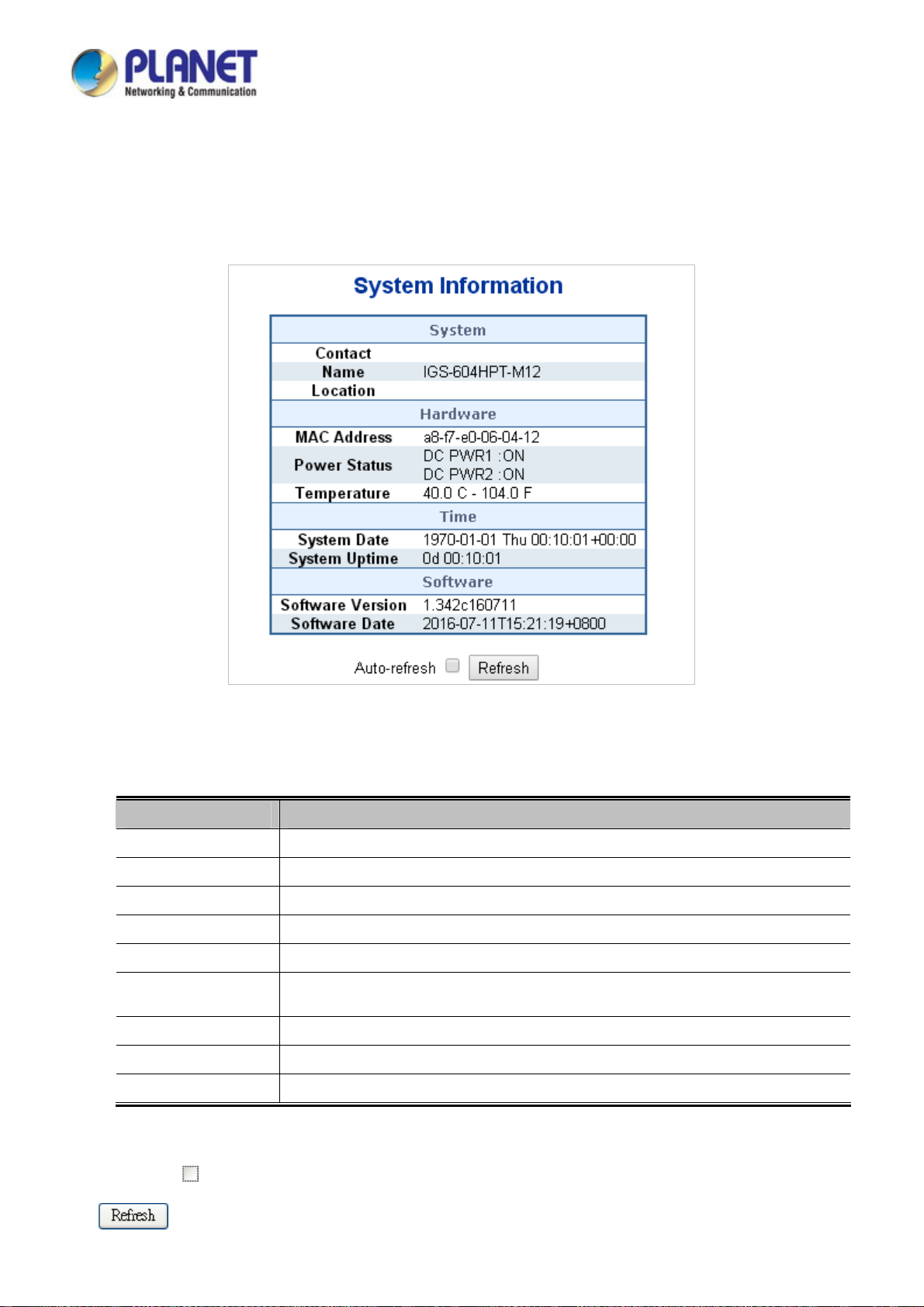
User’s Manual of IGS-604HPT-M12
4.2.1 System Information
The System Info page provides information for the current device information. System Info page helps a switch administrator to
identify the hardware MAC address, software version and system uptime. The screen in Figure 4-2-1 appears.
The page includes the following fields:
Object Description
Contact
Name
Location
MAC Addre ss
Temperature
System Date
System Uptime
Software Version
Software Date
The system contact configured in Configuration | System | Information | System Contact.
The system name configured in Configuration | System | Information | System Name.
The system location configured in Configuration | System | Information | System Location.
The MAC Address of this Industrial Managed Switch.
The Temperature shows the status of the current temperature of the switch.
The current (GMT) system time and date. The system time is obtained through the
configured SNTP Server, if any.
The period of time the device has been operational.
The software version of the Industrial Managed Switch.
The date when the switch software was produced.
Figure 4-2-1: System Information Screenshot
Buttons
Auto-refresh
: Check this box to refresh the page automatically. Automatic refresh occurs every 3 seconds.
: Click to refresh the page.
50
Page 51

User’s Manual of IGS-604HPT-M12
4.2.2 IP Configuration
The IP Configuration includes the IP Configuration, IP Interface and IP Routes. The configured column is used to view or
change the IP configuration. The maximum number of interfaces supported is 128 and the maximum number of routes is 32.
The screen in Figure 4-2-2 appears.
Figure 4-2-2: IP Configuration Screenshot
The current column is used to show the active IP configuration.
Object Description
IP Configurations
Mode
DNS Server
Configure whether the IP stack should act as a Host or a Router. In
Host mode, IP traffic between interfaces will not be routed. In Router
mode traffic is routed between all interfaces.
This setting controls the DNS name resolution done by the switch. The
following modes are supported:
From any DHCP interfaces
The first DNS server offered from a DHCP lease to a DHCP-enabled
interface will be used.
No DNS server
No DNS server will be used.
Configured
Explicitly provides the IP address of the DNS Server in dotted
decim
al notation.
51
Page 52

User’s Manual of IGS-604HPT-M12
IP Address
DNS Proxy
Delete
VLAN
IPv4
DHCP
IPv4
Enabled
Fallback
Current Lease
Address
From this DHCP interface
Specify from which DHCP-enabled interface a provided DNS server
should be preferred.
When DNS proxy is enabled, system will relay DNS requests to the
currently configured DNS server, and reply as a DNS resolver to the client
devices on the network.
Select this option to delete an existing IP interface.
The VLAN associated with the IP interface. Only ports in this VLAN will be
able to access the IP interface. This field is only available for input when
creating an new interface.
Enable the DHCP client by checking this box.
The number of seconds for trying to obtain a DHCP lease.
For DHCP interfaces with an active lease, this column show the current
interface address, as provided by the DHCP server.
Provide the IP address of this Industrial Managed Switch in dotted
decimal notation.
IP Routes
Mask Length
IPv6
Delete
Network
Mask Length
Gateway
Next Hop VLAN
Address
Mask Length
The IPv4 network mask, in number of bits (prefix length). Valid values are
between 0 and 30 bits for a IPv4 address.
Provide the IP address of this Industrial Managed Switch. A IPv6 address
is in 128-bit records represented as eight fields of up to four hexadecimal
digits with a colon separating each field (:).
The IPv6 network mask, in number of bits (prefix length). Valid values are
between 1 and 128 bits for a IPv6 address.
Select this option to delete an existing IP route.
The destination IP network or host address of this route. Valid format is
dotted decimal notationor a valid IPv6 notation. A default route can use
the value 0.0.0.0or IPv6 :: notation.
The destination IP network or host mask, in number of bits (prefix length).
The IP address of the IP gateway. Valid format is dotted decimal notation
or a valid IPv6 notation. Gateway and Network must be of the same type.
The VLAN ID (VID) of the specific IPv6 interface associated with the
gateway.
Buttons
: Click to add a new IP interface. A maximum of 128 interfaces is supported.
: Click to add a new IP route. A maximum of 32 routes is supported.
: Click to apply changes.
: Click to undo any changes made locally and revert to previously saved values.
52
Page 53

User’s Manual of IGS-604HPT-M12
4.2.3 IP Status
IP Status displays the status of the IP protocol layer. The status is defined by the IP interfaces, the IP routes and the neighbour
cache (ARP cache) status. The screen in Figure 4-2-3 appears.
Figure 4-2-3: IP Status Screenshot
The page includes the following fields:
Object Description
IP Interfaces
IP Routes
Neighbor Cache
Buttons
Interface
Type
Address
Status
Network
Gateway
Status
IP Address
Link Address
The name of the interface.
The address type of the entry. This may be LINK or IPv4.
The current address of the interface (of the given type).
The status flags of the interface (and/or address).
The destination IP network or host address of this route.
The gateway address of this route.
The status flags of the route.
The IP address of the entry.
The Link (MAC) address for which a binding to the IP address given exist.
Auto-refresh
: Check this box to refresh the page automatically. Automatic refresh occurs every 3 seconds.
: Click to refresh the page.
53
Page 54

User’s Manual of IGS-604HPT-M12
4.2.4 Users Configuration
This page provides an overview of the current users. Currently the only way to login as another user on the web server is to
close and reopen the browser. After setup is completed, press the “Apply” button to take effect. Please login web interface with
new user name and passwordas Figure 4-2-4 shows.
Figure 4-2-4: Users Configuration Screenshot
The page includes the following fields:
Buttons
Object Description
User Name
Privilege Level
: Click to add a new user.
The name identifying the user. This is also a link to Add/Edit User.
The privilege level of the user.
The allowed range is 1 to 15. If the privilege level value is 15, it can access all
groups, i.e. that is granted the fully control of the device. But others value need to
refer to each group privilege level. User's privilege should be same or greater
than the group privilege level to have the access of that group.
By default setting, most groups privilege level 5 has the read-only access and
privilege level 10 has the read-write access. And the system maintenance
(software upload, factory defaults and etc.) need user privilege level 15.
Generally, the privilege level 15 can be used for an administrator account,
privilege level 10 for a standard user account and privilege level 5 for a guest
account.
Add/Edit User
This page configures a user – add, edit or delete user.
54
Page 55

Figure 4-2-5: Add/Edit User Configuration Screenshot
The page includes the following fields:
Object Description
User’s Manual of IGS-604HPT-M12
Buttons
Username
Password
Password (again)
Privilege Level
: Click to apply changes.
: Click to undo any changes made locally and revert to previously saved values.
A string identifying the user name that this entry should belong to. The allowed
string length is 1 to 31. The valid user name is a combination of letters, numbers
and underscores.
The password of the user. The allowed string length is 1 to 31.
Please enter the user’s new password here again to confirm.
The privilege level of the user.
The allowed range is 1 to 15. If the privilege level value is 15, it can access all
groups, i.e. that is granted the fully control of the device. But others value need to
refer to each group privilege level. User's privilege should be same or greater
than the group privilege level to have the access of that group.
: Click to undo any changes made locally and return to the Users.
: Delete the current user. This button is not available for new configurations (Add new user)
By default setting, most groups privilege level 5 has the read-only access and privilege level 10 has the
read-write access. And the system maintenance (software upload, factory defaults, etc.) needs user
privilege level 15.
55
Page 56

User’s Manual of IGS-604HPT-M12
Generally, the privilege level 15 can be used for an administrator account, privilege level 10 for a
standard user account and privilege level 5 for a guest account.
Once the new user is added, the new user entry is shown on the Users Configuration page.
igure 4-2-6: User Configuration Screenshot
F
If you forget the new password after changing the default password, please press the “Reset”
button on the front panel of the Industrial Managed Switch for over 10 seconds and then release
it. The current setting including VLAN will be lost and the Industrial Managed Switch will restore
to the default mode.
56
Page 57

User’s Manual of IGS-604HPT-M12
4.2.5 Privilege Levels
This page provides an overview of the privilege levels. After setup is completed, please press the “Apply” button to take effect.
Please login web interface with new user name and password and the screen in Figure 4-2-7 appears.
Figure 4-2-7: Privilege Levels Configuration Screenshot
57
Page 58

The page includes the following fields:
Object Description
User’s Manual of IGS-604HPT-M12
Group Name
Privilege Level
The name identifying the privilege group. In most cases, a privilege level group
consists of a single module (e.g. LACP, RSTP or QoS), but a few of them contain
more than one. The following description defines these privilege level groups in
details:
System: Contact, Name, Location, Timezone, Log.
Security: Authentication, System Access Management, Port (contains Dot1x
port, MAC based and the MAC Address Limit), ACL, HTTPS, SSH, ARP
Inspection and IP source guard.
IP: Everything except 'ping'.
Port: Everything except 'VeriPHY'.
Diagnostics: 'ping' and 'VeriPHY'.
Maintenance: CLI- System Reboot, System Restore Default, System
Password, Configuration Save, Configuration Load and Firmware Load.
Web- Users, Privilege Levels and everything in Maintenance.
Debug: Only present in CLI.
Every privilege level group has an authorization level for the following sub
groups:
Buttons
Configuration read-only
Configuration/execute read-write
Status/statistics read-only
Status/statistics read-write (e.g., for clearing of statistics).
: Click to apply changes.
: Click to undo any changes made locally and revert to previously saved values.
58
Page 59
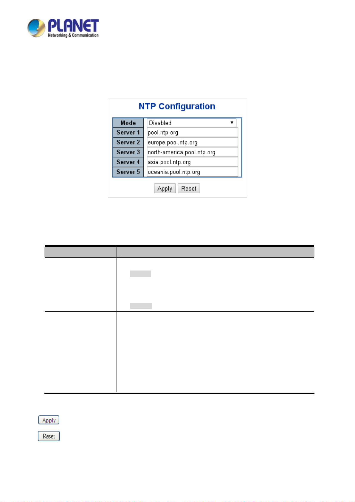
User’s Manual of IGS-604HPT-M12
4.2.6 NTP Configuration
Configure NTP on this page. NTP is an acronym for Network Time Protocol, a network protocol for synchronizing the clocks of
computer systems. NTP uses UDP (data grams) as transport layer. You can specify NTP Servers. The NTP Configuration
screen in Figure 4-2-8 appears.
The page includes the following fields:
Object Description
Mode
Server #
Figure 4-2-8: NTP Configuration Screenshot
Indicates the NTP mode operation. Possible modes are:
Enabled: Enable NTP mode operation. When enable NTP mode operation,
the agent forward and to transfer NTP messages between the clients and the
server when they are not on the same subnet domain.
Disabled: Disable NTP mode operation.
Provide the NTP IPv4 or IPv6 address of this switch. IPv6 address is in 128-bit
records represented as eight fields of up to four hexadecimal digits with a colon
separates each field (:).
For example, 'fe80::215:c5ff:fe03:4dc7'. The symbol '::' is a special syntax that
can be used as a shorthand way of representing multiple 16-bit groups of
Buttons
contiguous zeros; but it can only appear once. It also used a following legally
IPv4 address. For example, '::192.1.2.34'.
: Click to apply changes.
: Click to undo any changes made locally and revert to previously saved values.
59
Page 60
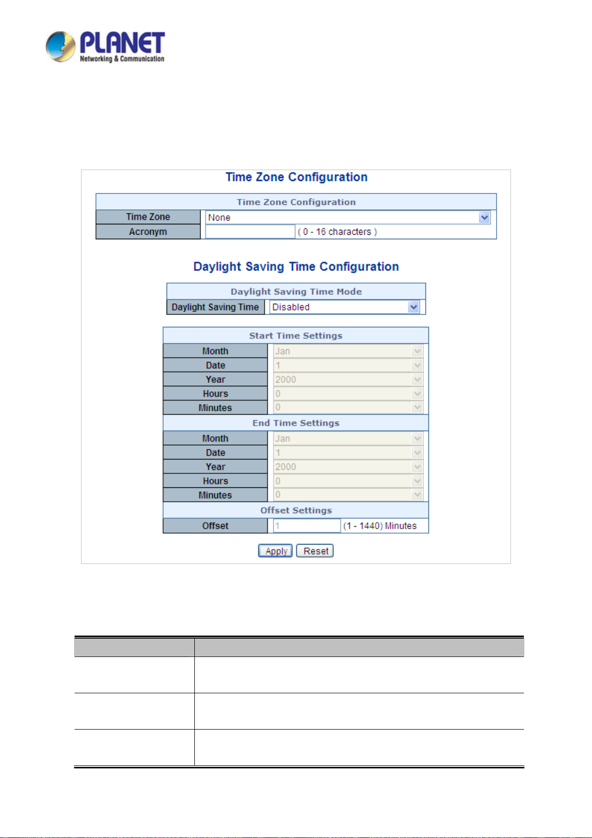
User’s Manual of IGS-604HPT-M12
4.2.7 Time Configuration
Configure Time Zone on this page. A Time Zone is a region that has a uniform standard time for legal, commercial, and social
purposes. It is convenient for areas in close commercial or other communication to keep the same time, so time zones tend to
follow the boundaries of countries and their subdivisions. The Time Zone Configuration screen in Figure 4-2-9 appears
The page includes the following fields:
Object Description
Time Zone
Acronym
Daylight Saving Time
Figure 4-2-9: Time
Lists various Time Zones worldwide. Select appropriate Time Zone from the
drop-down menu and click Save to set.
User can set the acronym of the time zone. This is a User configurable acronym
to identify the time zone. ( Range : Up to 16 characters )
This is used to set the clock forward or backward according to the configurations
set below for a defined Daylight Saving Time duration. Select 'Disable' to disable
Configuration Screenshot
60
Page 61
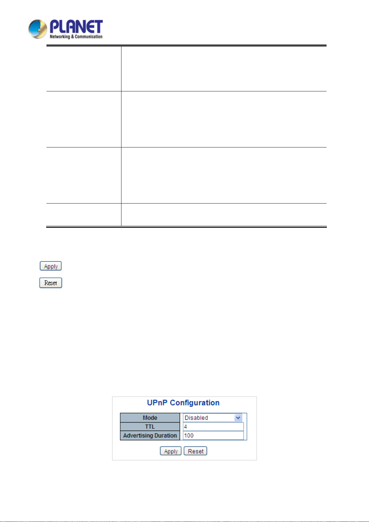
User’s Manual of IGS-604HPT-M12
the Daylight Saving Time configuration. Select 'Recurring' and configure the
Daylight Saving Time duration to repeat the configuration every year. Select
'Non-Recurring' and configure the Daylight Saving Time duration for single time
configuration. ( Default : Disabled ).
Start Time Settings Week - Select the starting week number.
Day - Select the starting day.
Month - Select the starting month.
Hours - Select the starting hour.
Minutes - Select the starting minute.
End Time Settings Week - Select the ending week number.
Day - Select the ending day.
Month - Select the ending month.
Hours - Select the ending hour.
Minutes - Select the ending minute
Offset Settings
Buttons
: Click to apply changes.
: Click to undo any changes made locally and revert to previously saved values.
Enter the number of minutes to add during Daylight Saving Time. ( Range: 1 to
1440 )
4.2.8 UPnP
Configure UPnP on this page. UPnP is an acronym for Universal Plug and Play. The goals of UPnP are to allow devices to
connect seamlessly and to simplify the implementation of networks in the home (data sharing, communications, and
entertainment) and in corporate environments for simplified installation of computer components. The UPnP Configuration
screen in Figure 4-2-10 appears.
Figure 4-2-10: UPnP
Configuration Screenshot
61
Page 62

The page includes the following fields:
Object Description
User’s Manual of IGS-604HPT-M12
Mode
TTL
Advertising Duration
Indicates the UPnP operation mode. Possible modes are:
Enabled: Enable UPnP mode operation.
Disabled: Disable UPnP mode operation.
When the mode is enabled, two ACEs are added automatically to trap UPnP
related packets to CPU. The ACEs are automatically removed when the mode is
disabled.
The TTL value is used by UPnP to send SSDP advertisement messages.
Valid values are in the range of 1 to 255.
The duration, carried in SSDP packets, is used to inform a control point or control
points how often it or they should receive a SSDP advertisement message from
this switch. If a control point does not receive any message within the duration, it
will think that the switch no longer exists. Due to the unreliable nature of UDP, in
the standard it is recommended that such refreshing of advertisements to be
done at less than one-half of the advertising duration. In the implementation, the
switch sends SSDP messages periodically at the interval one-half of the
advertising duration minus 30 seconds. Valid values are in the range 100 to
86400.
Buttons
: Click to apply changes
: Click to undo any changes made locally and revert to previously saved values.
Figure 4-2-11: UPnP
devices show on Windows My Network Place
62
Page 63

User’s Manual of IGS-604HPT-M12
4.2.9 DHCP Relay
Configure DHCP Relay on this page. DHCP Relay is used to forward and to transfer DHCP messages between the clients and
the server when they are not on the same subnet domain.
The DHCP option 82 enables a DHCP relay agent to insert specific information into a DHCP request packets when forwarding
client DHCP packets to a DHCP server and remove the specific information from a DHCP reply packets when forwarding server
DHCP packets to a DHCP client. The DHCP server can use this information to implement IP address or other assignment
policies. Specifically the option works by setting two sub-options:
Circuit ID (option 1)
Remote ID (option 2).
The Circuit ID sub-option is supposed to include information specific to which circuit the request came in on.
The Remote ID sub-option was designed to carry information relating to the remote host end of the circuit.
The definition of Circuit ID in the switch is 4 bytes in length and the format is "vlan_id" "module_id" "port_no". The parameter of
"vlan_id" is the first two bytes representing the VLAN ID. The parameter of "module_id" is the third byte for the module ID (in
standalone switch it always equals 0; in stackable switch it means switch ID). The parameter of "port_no" is the fourth byte and it
means the port number.
The Remote ID is 6 bytes in length, and the value equals the DHCP relay agent’s MAC address. The DHCP Relay Configuration
screen in Figure 4-2-12 appears.
Figure 4-2-12 DHCP Relay
The page includes the following fields:
Configuration Screenshot
Object Description
Relay Mode
Indicates the DHCP relay mode operation. Possible modes are:
Enabled: Enable DHCP relay mode operation. When enabling DHCP relay
mode operation, the agent forwards and transfers DHCP messages between
the clients and the server when they are not on the same subnet domain.
And the DHCP broadcast message won't flood for security considered.
Disabled: Disable DHCP relay mode operation.
Relay Server
Indicates the DHCP relay server IP address. A DHCP relay agent is used to
63
Page 64

User’s Manual of IGS-604HPT-M12
forward and transfer DHCP messages between the clients and the server when
they are not on the same subnet domain.
Relay Information
Mode
Relay Information
Policy
Indicates the DHCP relay information mode option operation. Possible modes
are:
Enabled: Enable DHCP relay information mode operation. When enabling
DHCP relay information mode operation, the agent inserts specific
information (option82) into a DHCP message when forwarding to DHCP
server and removing it from a DHCP message when transferring to DHCP
client. It only works under DHCP relay operation mode enabled.
Disabled: Disable DHCP relay information mode operation.
Indicates the DHCP relay information option policy. When enabling DHCP relay
information mode operation, if agent receives a DHCP message that already
contains relay agent information. It will enforce the policy. And it only works under
DHCP relay information operation mode enabled. Possible policies are:
Replace: Replace the original relay information when receiving a DHCP
message that already contains it.
Keep: Keep the original relay information when receiving a DHCP message
that already contains it.
Drop: Drop the package when receiving a DHCP message that already
Buttons
contains relay information.
: Click to apply changes
: Click to undo any changes made locally and revert to previously saved values.
64
Page 65
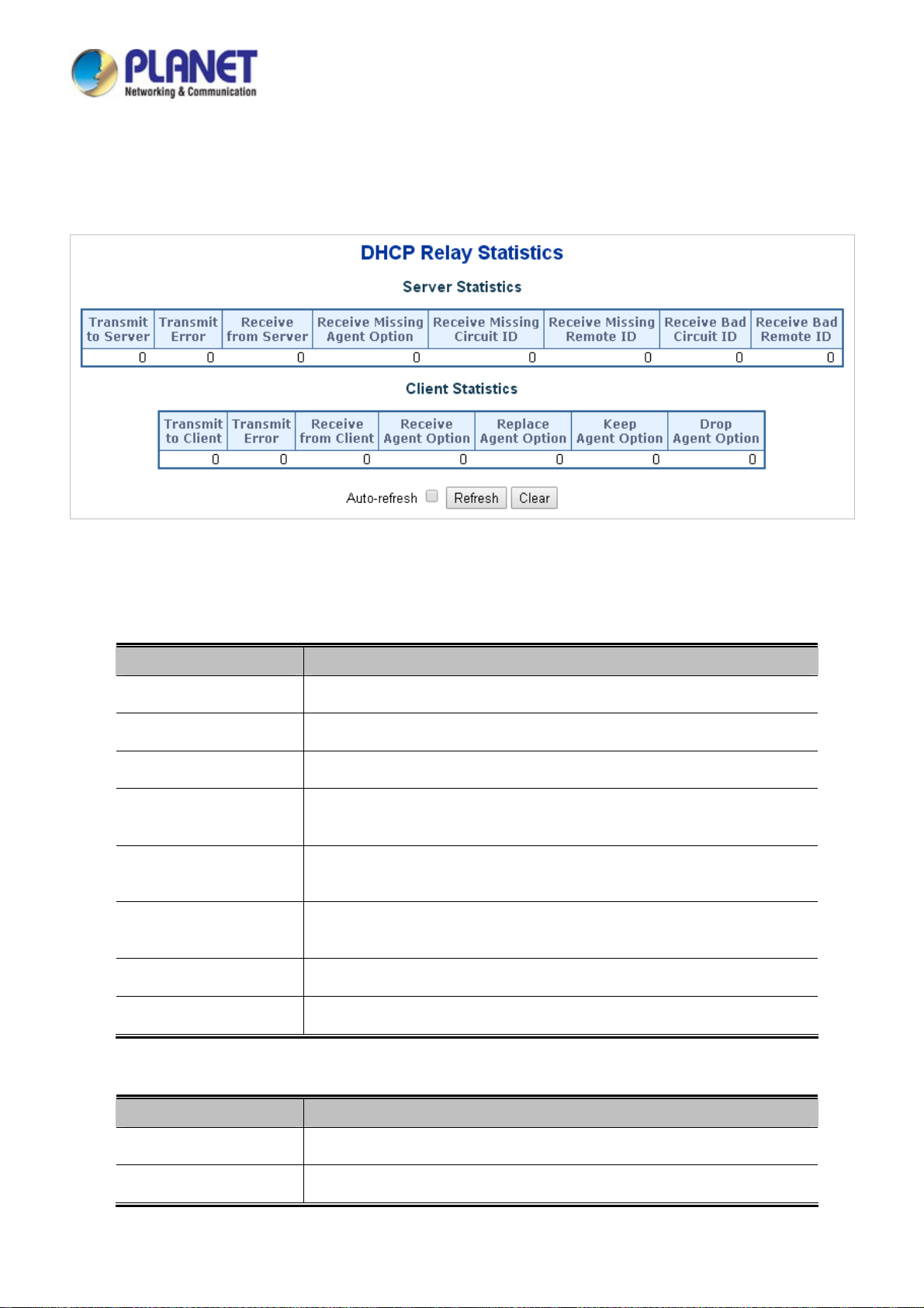
User’s Manual of IGS-604HPT-M12
4.2.10 DHCP Relay Statistics
This page provides statistics for DHCP relay. The DHCP Relay Statistics screen in Figure 4-2-13 appears.
The page includes the following fields:
Server Statistics
Object Description
Transmit to Server
Transmit Error
Receive from Server
Receive Missing Agent
Option
Receive Missing
Circuit ID
Receive Missing
Remote ID
Figure 4-2-13: DHCP Relay Statistics Screenshot
The packets number that is relayed from client to server.
The packets number whose errors are sending to clients.
The packets number that is received from server.
The packets number that is received without agent information options.
The packets number whose missing circuit ID is received.
The packets number whose missing remote ID is received.
Receive Bad Circuit ID
Receive Bad Remote ID
Client Statistics
Object Description
Transmit to Client
Transmit Error
The packets number whose Circuit ID does not match known circuit ID.
The packets number whose Remote ID does not match known remote ID.
The packets number that is relayed from server to client.
The packets number that is erroneously sent to servers.
65
Page 66

User’s Manual of IGS-604HPT-M12
Receive from Client
Receive Agent Option
Replace Agent Option
Keep Agent Option
Drop Agent Option
Buttons
Auto-refresh : Check this box to refresh the page automatically. Automatic refresh occurs every 3 seconds.
: Click to refresh the page immediately.
: Clears all statistics.
The packets number that is received from server.
The packets number that is received with relay agent information option.
The packets number that is replaced with relay agent information option.
The packets number that keeps relay agent information option.
The packets number that drops relay agent information option.
66
Page 67
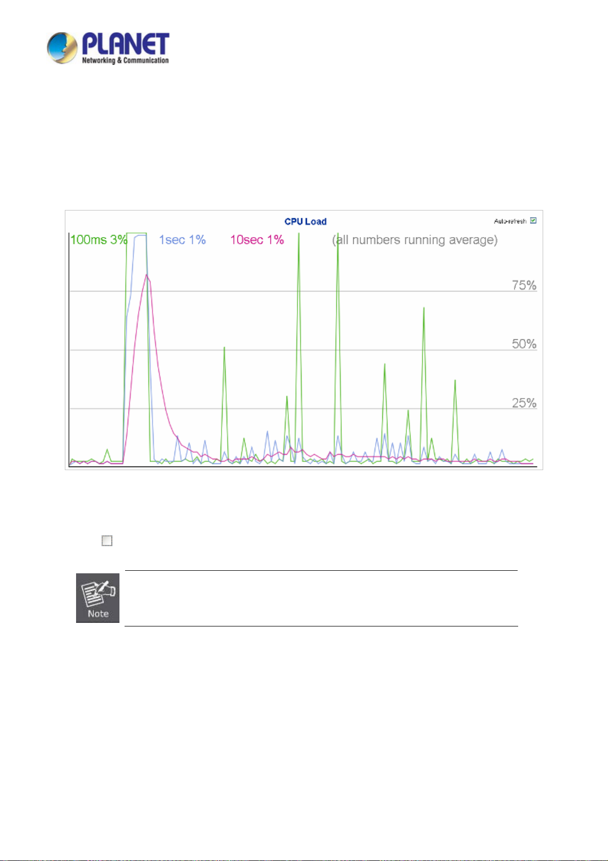
User’s Manual of IGS-604HPT-M12
4.2.11 CPU Load
This page displays the CPU load, using an SVG graph. The load is measured as average over the last 100ms, 1sec and 10
seconds intervals. The last 120 samples are graphed, and the last numbers are displayed as text as well. In order to display the
SVG graph, your browser must support the SVG format. Consult the SVG Wiki for more information on browser support.
Specifically, at the time of writing, Microsoft Internet Explorer will need to have a plugin installed to support SVG. The CPU Load
screen in Figure 4-2-14 appears.
Buttons
Auto-refresh
Figure 4-2-14: CPU Load Screenshot
: Check this box to refresh the page automatically. Automatic refresh occurs every 3 seconds.
If your browser cannot display anything on this page, please download Adobe SVG tool and
install it in your computer.
67
Page 68

User’s Manual of IGS-604HPT-M12
4.2.12 System Log
The Industrial Managed Switch system log information is provided here. The System Log screen in Figure 4-2-15 appears.
The page includes the following fields:
Object Description
ID
Level
Clear Level
Figure 4-2-15: System Log Screenshot
The ID (>= 1) of the system log entry.
The level of the system log entry. The following level types are supported:
Info: Information level of the system log.
Warning: Warning level of the system log.
Error: Error level of the system log.
All: All levels.
To clear the system log entry level. The following level types are supported:
Info: Information level of the system log.
Warning: Warning level of the system log.
Error: Error level of the system log.
All: All levels.
Time
Message
Buttons
Auto-refresh : Check this box to refresh the page automatically. Automatic refresh occurs every 3 seconds.
: Updates the system log entries, starting from the current entry ID.
: Flushes the selected log entries.
: Hides the selected log entries.
The time of the system log entry.
The message of the system log entry.
68
Page 69

User’s Manual of IGS-604HPT-M12
: Downloads the selected log entries.
: Updates the system log entries, starting from the first available entry ID.
: Updates the system log entries, ending at the last entry currently displayed.
: Updates the system log entries, starting from the last entry currently displayed.
: Updates the system log entries, ending at the last available entry ID.
4.2.13 Detailed Log
The Industrial Managed Switch system detailed log information is provided here. The Detailed Log screen in Figure 4-2-16
appears.
The page includes the following fields:
Object Description
ID
Message
Buttons
: Download the system log entry to the current entry ID.
: Updates the system log entry to the current entry ID.
: Updates the system log entry to the first available entry ID.
: Updates the system log entry to the previous available entry ID.
: Updates the system log entry to the next available entry ID.
Figure 4-2-16: Detailed Log Screenshot
The ID (>= 1) of the system log entry.
The message of the system log entry.
: Updates the system log entry to the last available entry ID.
: Print the system log entry to the current entry ID.
69
Page 70
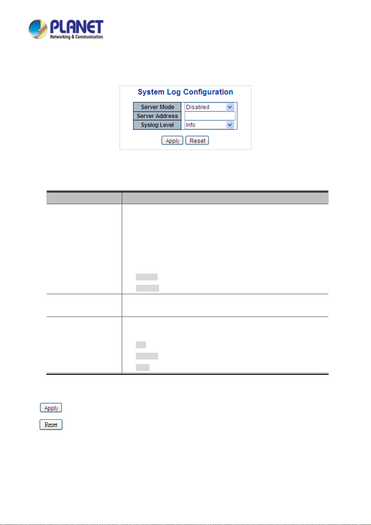
User’s Manual of IGS-604HPT-M12
4.2.14 Remote Syslog
Configure remote syslog on this page. The Remote Syslog screen in Figure 4-2-17 appears.
Figure 4-2-17: Remote Syslog Screenshot
The page includes the following fields:
Object Description
Mode
Indicates the server mode operation. When the mode operation is enabled, the
syslog message will send out to syslog server. The syslog protocol is based on
UDP communication and received on UDP port 514 and the syslog server will not
send acknowledgments back to sender since UDP is a connectionless protocol
and it does not provide acknowledgments. The syslog packet will always be sent
out even if the syslog server does not exist. Possible modes are:
Enabled: Enable remote syslog mode operation.
Disabled: Disable remote syslog mode operation.
Syslog Server IP
Syslog Level
Indicates the IPv4 host address of syslog server. If the switch provides DNS
feature, it also can be a host name.
Indicates what kind of message will be sent to syslog server. Possible modes
are:
Info: Send information, warnings and errors.
Warning: Send warnings and errors.
Error: Send errors.
Buttons
: Click to apply changes
: Click to undo any changes made locally and revert to previously saved values.
70
Page 71

User’s Manual of IGS-604HPT-M12
4.2.15 SMTP Configuration
This page facilitates an SMTP Configuration on the switch. The SMTP Configure screen in Figure 4-2-18 appears.
The page includes the following fields:
Object Description
SMTP Mode
SMTP Server
SMTP Port
SMTP Authentication
Authentication User
Name
Authentication
Password
E-mail From
E-mail Subject
Figure 4-2-18: SMTP Configuration Screenshot
Controls whether SMTP is enabled on this switch.
Type the SMTP server name or the IP address of the SMTP server.
Set port number of SMTP service.
Controls whether SMTP Authentication is enabled If authentication is required
when an e-mail is sent.
Type the user name for the SMTP server if Authentication is Enable.
Type the password for the SMTP server if Authentication is Enable.
Type the sender’s E-mail address. This address is used for replying e-mails.
Type the subject/title of the e-mail.
Buttons
E-mail 1 To
E-mail 2 To
: Send a test mail to mail server to check this account is available or not.
: Click to save changes.
: Click to undo any changes made locally and revert to previously saved values.
Type the receiver’s e-mail address.
71
Page 72

User’s Manual of IGS-604HPT-M12
4.2.16 Fault Alarm
This page facilitates an update of the firmware controlling the switch. The Web Firmware Upgrade screen in Figure 4-2-19
appears.
Figure 4-2-19: Fault Alarm Control Configuration Screenshot
The page includes the following fields:
Object Description
Enable
Record
Action
Port Alarm
Buttons
: Click to apply changes
: Click to undo any changes made locally and revert to previously saved values.
Controls whether Fault Alarm is enabled on this switch.
Controls whether Record is sending System log or SNMP Trap or both.
Controls whether Port Fail or Power Fail or both for fault detecting.
Controls which Ports or all for fault detecting.
72
Page 73
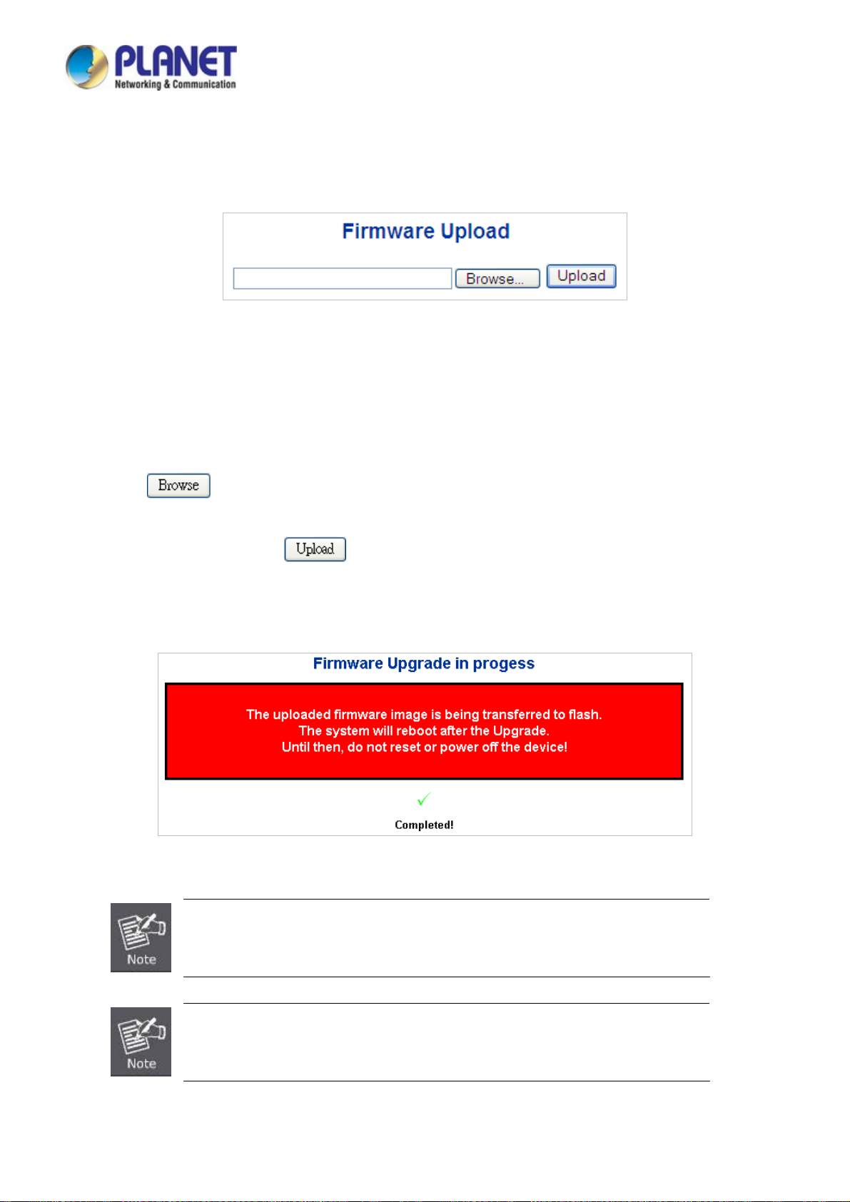
User’s Manual of IGS-604HPT-M12
4.2.17 Web Firmware Upgrade
This page facilitates an update of the firmware controlling the switch. The Web Firmware Upgrade screen in Figure 4-2-20
appears.
Figure 4-2-20: Web Firmware Upgrade Screenshot
To open Firmware Upgrade screen, perform the following:
1. Click System -> Web Firmware Upgrade.
2. The Firmware Upgrade screen is displayed as in Figure 4-2-21.
3. Click the “
4. Select on the firmware then click “
5. Once the software is loaded to the system successfully, the following screen appears. The system will load the new
software after reboot.
“button of the Main page, the system would pop up the file selection menu to choose firmware.
”, the Software Upload Progress would show the file with upload status.
Figure 4-2-21: Software Successfully Loaded Notice Screen
DO NOT Power OFF the Industrial Managed Switch until the update progress is completed.
Do not quit the Firmware Upgrade page without pressing the “OK” button after the image is
loaded. Or the system won’t apply the new firmware. User has to repeat the firmware
upgrade process.
73
Page 74
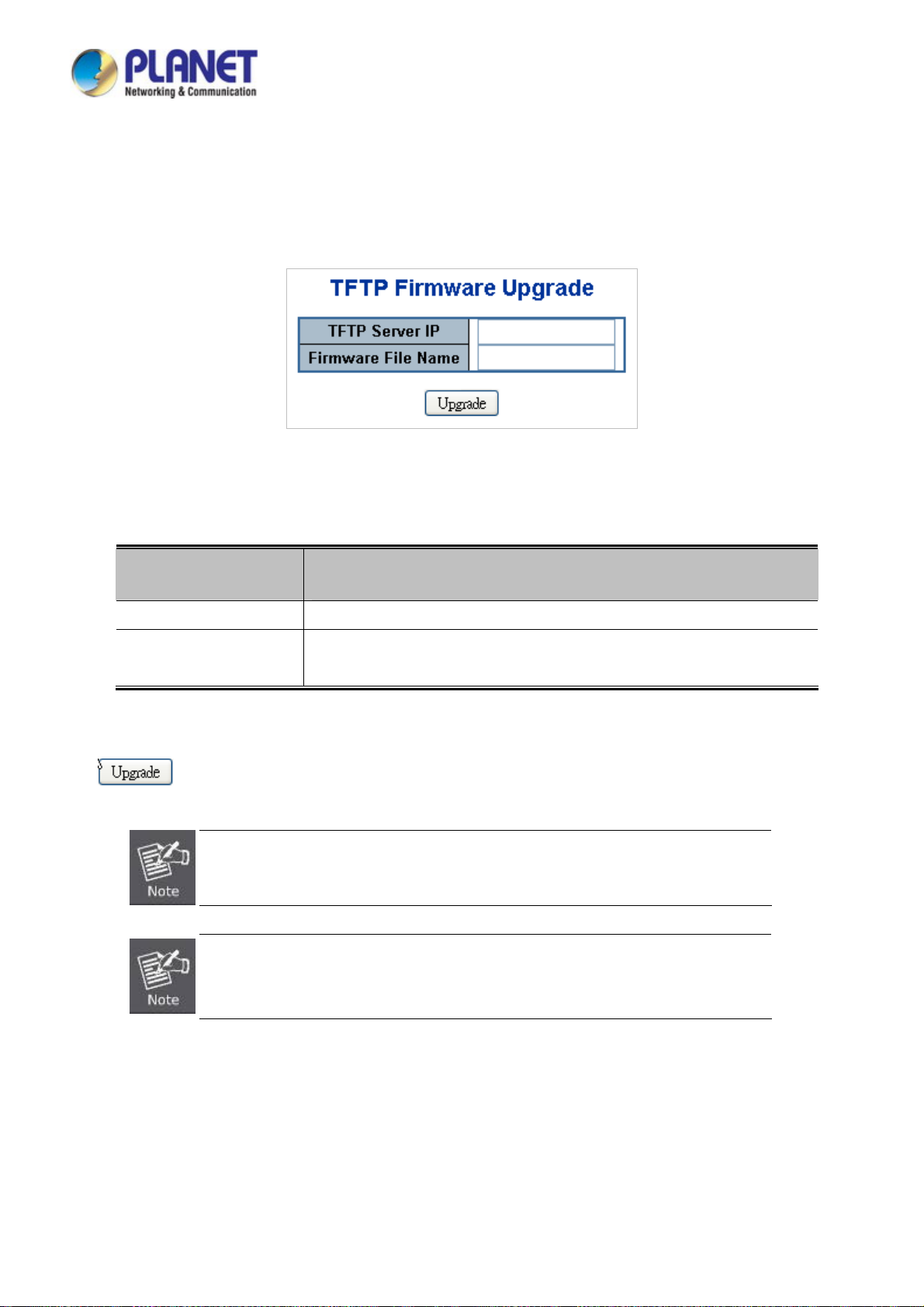
User’s Manual of IGS-604HPT-M12
4.2.18 TFTP Firmware Upgrade
The Firmware Upgrade page provides the functions to allow a user to update the Industrial Managed Switch firmware from the
TFTP server in the network. Before updating, make sure you have your TFTP server ready and the firmware image is on the
TFTP server. The TFTP Firmware Upgrade screen in Figure 4-2-22 appears.
Figure 4-2-22: TFTP Firmware Update Screenshot
The page includes the following fields:
Object Description
TFTP Server IP
Firmware File Name
Buttons
: Click to upgrade firmware.
DO NOT Power OFF the Industrial Managed Switch until the update progress is completed.
Do not quit the Firmware Upgrade page without pressing the “OK” button after the image is
Fill in your TFTP server IP address.
The name of firmware image.
(Maximum length: 24 characters)
loaded. Or the system won’t apply the new firmware. User has to repeat the firmware
upgrade process.
74
Page 75

User’s Manual of IGS-604HPT-M12
4.2.19 Save Startup Config
This function allows to save the current configuration, thereby ensuring that the current active configuration can be used at the
next reboot screen in Figure 4-2-23 as shown below. After saving the configuration, the screen in Figure 4-2-24 appears.
Figure 4-2-23: Configuration Save Screenshot
Figure 4-2-24: Finish Saving Screenshot
4.2.20 Configuration Download
The switch stores its configuration in a number of text files in CLI format. The files are either virtual (RAM-based) or stored in
flash on the switch.
There are three system files:
running-config: A virtual file that represents the currently active configuration on the switch. This file is volatile.
startup-config: The startup configuration for the switch reads at boot time.
default-config: A read-only file with vendor-specific configuration. This file is read when the system is restored to default
settings.
It is also possible to store up to two other files and apply them to running-config, thereby switching configuration.
Configuration Download page allows the downloads of the running-config, startup-config and default-config on the switch.
Please refer to Figure 4-2-25 shown below.
Figure 4-2-25: Configuration Download Screenshot
75
Page 76
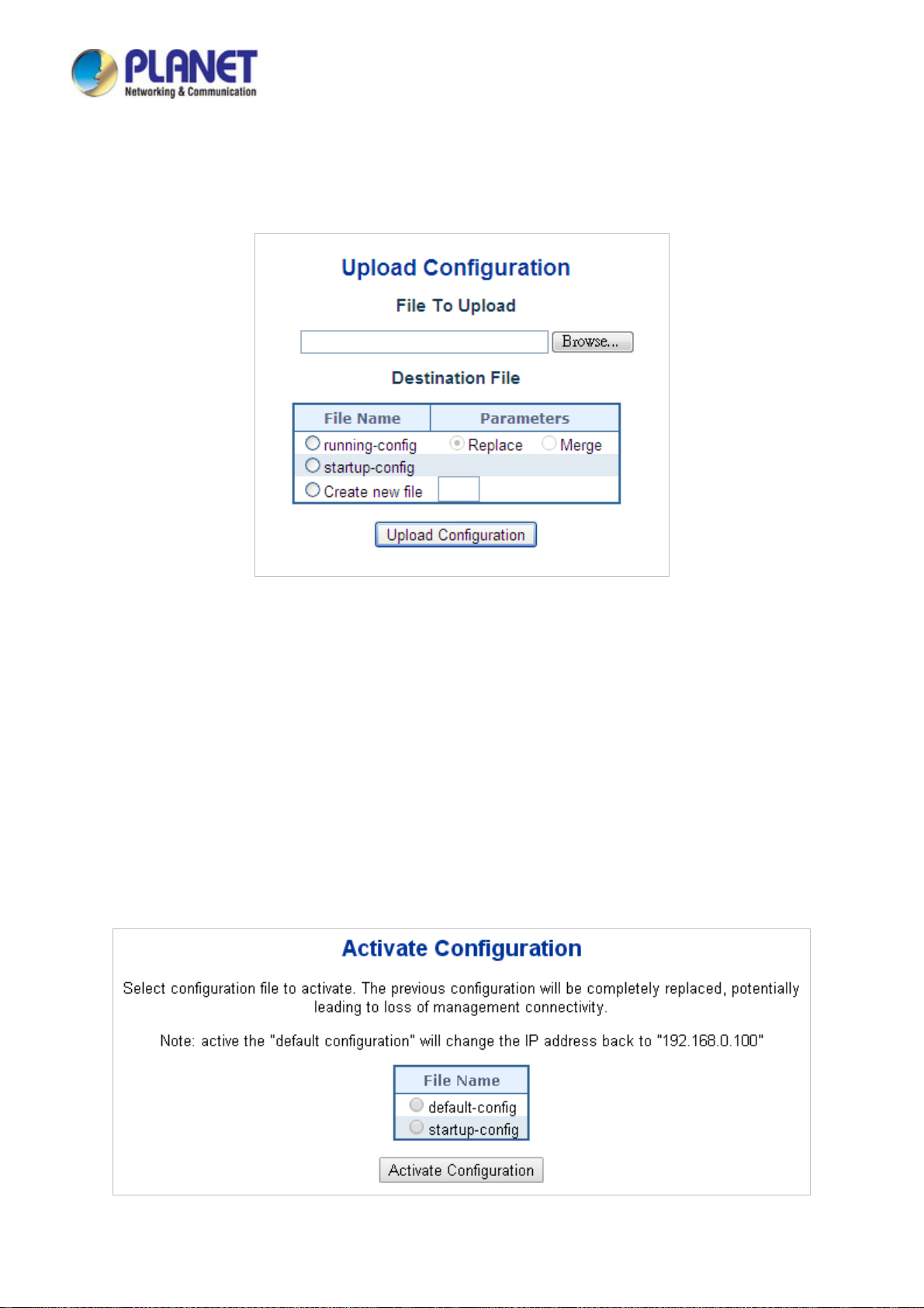
User’s Manual of IGS-604HPT-M12
4.2.21 Configuration Upload
Configuration Upload page allows the uploads of the running-config and startup-config on the switch. Please refer to Figure
4-2-26 shown below.
Figure 4-2-26: Configuration Upload Screenshot
If the destination is running-config, the file will be applied to the switch configuration. This can be done in two ways:
Replace mode: The current configuration is fully replaced with the configuration in the uploaded file.
Merge mode: The uploaded file is merged into running-config.
If the file system is full (i.e. contains the three system files mentioned above plus two other files), it is not possible to create new
files, but an existing file must be overwritten or another deleted first.
4.2.22 Configuration Activate
Configuration Activate page allows to activate the startup-config and default-config files present on the switch. Please refer to
Figure 4-2-27 shown below.
Figure 4-2-27: Configuration Activate Screenshot
76
Page 77
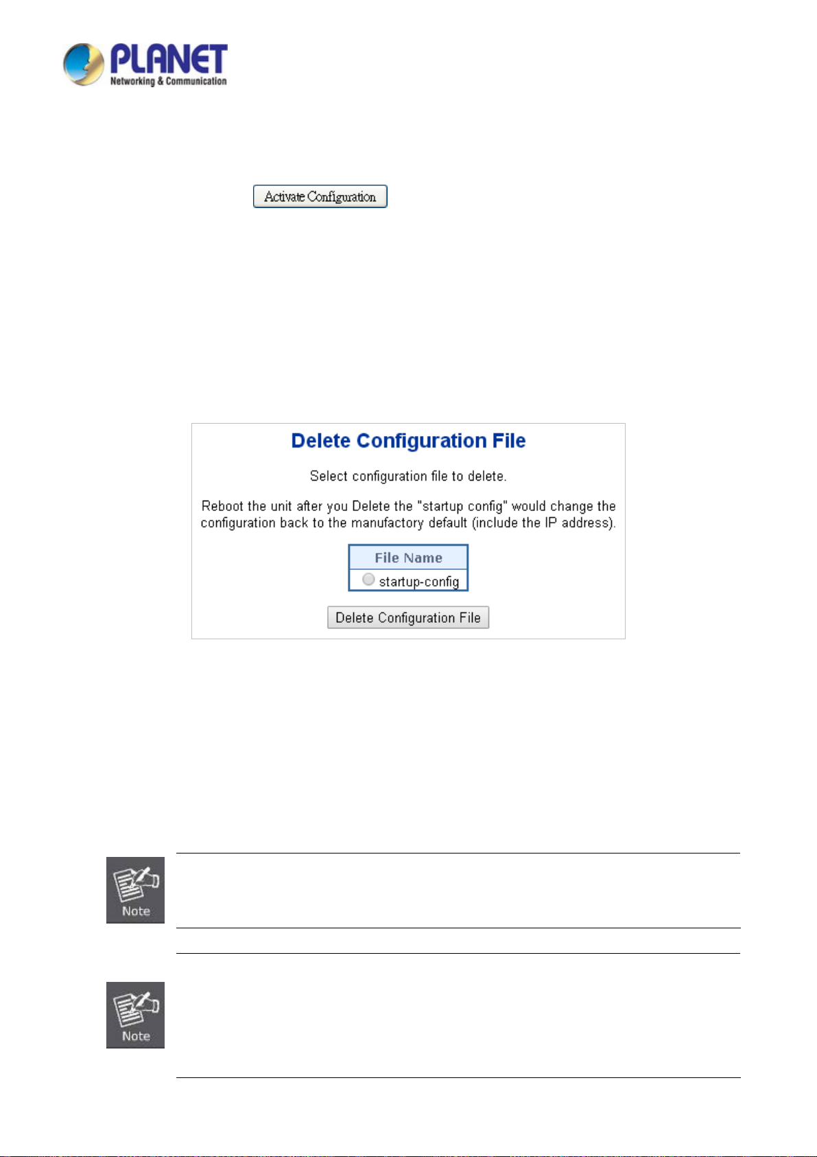
User’s Manual of IGS-604HPT-M12
It is possible to activate any of the configuration files present on the switch, except for running-config which represents the
currently active configuration.
Select the file to activate and click
configuration with that of the selected file.
. This will initiate the process of completely replacing the existing
4.2.23 Configuration Delete
Configuration Delete page allows to delete the startup-config and default-config files which are stored in FLASH. If this is done
and the switch is rebooted without a prior Save operation, this effectively resets the switch to default configuration. Please refer
to Figure 4-2-28 shown below.
Figure 4-2-28: Configuration Delete Screenshot
4.2.24 Image Select
This page provides information about the active and alternate (backup) firmware images in the device, and allows you to revert
to the alternate image. The web page displays two tables with information about the active and alternate firmware images. The
Image Select screen in Figure 4-2-29 appears.
In case the active firmware image is the alternate image, only the "Active Image" table is shown. In this
case, the Activate Alternate Image button is also disabled.
1. If the alternate image is active (due to a corruption of the primary image or by manual
intervention), uploading a new firmware image to the device will automatically use the primary
image slot and activate this.
2. The firmware version and date information may be empty for older firmware releases. This does
not constitute an error.
77
Page 78

Figure 4-2-29: Software Image Selection Screenshot
The page includes the following fields:
User’s Manual of IGS-604HPT-M12
Object Description
Image
Version
Date
Buttons
: Click to use the alternate image. This button may be disabled depending on system state.
The flash index name of the firmware image. The name of primary (preferred)
image is image, the alternate image is named image.bk.
The version of the firmware image.
The date where the firmware was produced.
4.2.25 Factory Default
You can reset the configuration of the Industrial Managed Switch on this page. Only the IP configuration is retained. The new
configuration is available immediately, which means that no restart is necessary. The Factory Default screen in Figure 4-2-30
appears.
Figure 4-2-30: Factory Default Screenshot
78
Page 79
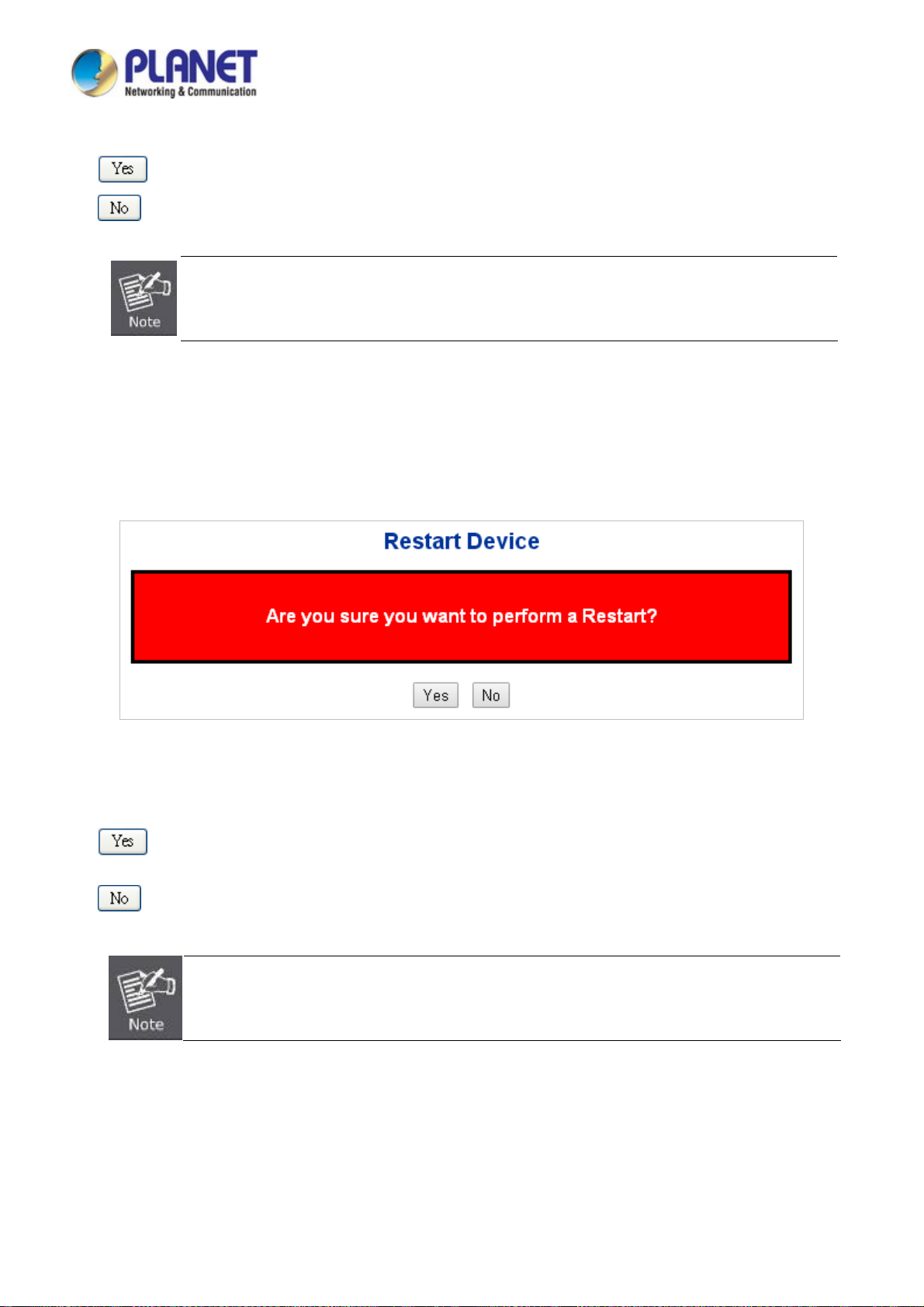
User’s Manual of IGS-604HPT-M12
Buttons
: Click to reset the configuration to Factory Defaults.
: Click to return to the Port State page without resetting the configuration.
To reset the Industrial Managed Switch to the Factory default setting, you can also press the hardware
reset button on the front panel for about 10 seconds. After the device is rebooted, you can login the
management Web interface within the same subnet of 192.168.0.xx.
4.2.26 System Reboot
The Reboot page enables the device to be rebooted from a remote location. Once the Reboot button is pressed, users have to
re-login the Web interface for about 60 seconds later as the System Reboot screen in Figure 4-2-31 appears.
Buttons
Figure 4-2-31: System Reboot Screenshot
: Click to reboot the system.
: Click to return to the Port State page without rebooting the system.
You can also check the SYS LED on the front panel to identify whether the System is loaded completely or
not. If the SYS LED is blinking, then it is in the firmware load stage; if the SYS LED light is on, you can use
the Web browser to login the Industrial Managed Switch.
79
Page 80

User’s Manual of IGS-604HPT-M12
4.3 Simple Network Management Protocol
4.3.1 SNMP Overview
The Simple Network Management Protocol (SNMP) is an application layer protocol that facilitates the exchange of management
information between network devices. It is part of the Transmission Control Protocol/Internet Protocol (TCP/IP) protocol suite.
SNMP enables network administrators to manage network performance, find and solve network problems, and plan for network
growth.
An SNMP-managed network consists of three key components: Network management stations (NMSs), SNMP agents,
Management information base (MIB) and network-management protocol:
■ Network management stations (NMSs):Sometimes called consoles, these devices execute management applications
that monitor and control network elements. Physically, NMSs are usually engineering workstation-caliber computers with
fast CPUs, megapixel color displays, substantial memory, and abundant disk space. At least one NMS must be present in
each managed environment.
■ Agents:Agents are software modules that reside in network elements. They collect and store management information
such as the number of error packets received by a network element.
■ Management information base (MIB):A MIB is a collection of managed objects residing in a virtual information store.
Collections of related managed objects are defined in specific MIB modules.
■ Network management protocol:A management protocol is used to convey management information between agents
and NMSs. SNMP is the Internet community's de facto standard management protocol.
SNMP Operations
SNMP itself is a simple request/response protocol. NMSs can send multiple requests without receiving a response.
■ Get -- Allows the NMS to retrieve an object instance from the agent.
■ Set -- Allows the NMS to set values for object instances within an agent.
■ Tra p - - Used by the agent to asynchronously inform the NMS of some event. The SNMPv2 trap message is designed to
replace the SNMPv1 trap message.
80
Page 81

User’s Manual of IGS-604HPT-M12
SNMP community
An SNMP community is the group that devices and management stations running SNMP belong to. It helps define where
information is sent. The community name is used to identify the group. A SNMP device or agent may belong to more than one
SNMP community. It will not respond to requests from management stations that do not belong to one of its communities. SNMP
default communities are:
。 Write = private
。 Read = public
Use the SNMP Menu to display or configure the Industrial Managed Switch's SNMP function. This section has the following
items:
System Configuration
Trap Configuration
System Information
SNMPv3 Communities
SNMPv3 Users
SNMPv3 Groups
SNMPv3 Views
SNMPv3 Access
Configure SNMP on this page.
Configure SNMP trap on this page.
The system information is provided here.
Configure SNMPv3 communities table on this page.
Configure SNMPv3 users table on this page.
Configure SNMPv3 groups table on this page.
Configure SNMPv3 views table on this page.
Configure SNMPv3 accesses table on this page.
4.3.2 SNMP System Configuration
Configure SNMP on this page. The SNMP System Configuration screen in Figure 4-3-1 appears.
Figure 4-3-1: SNMP System Configuration Screenshot
81
Page 82

The page includes the following fields:
Object Description
User’s Manual of IGS-604HPT-M12
Mode
Version
Read Community
Write Community
Indicates the SNMP mode operation. Possible modes are:
Enabled: Enable SNMP mode operation.
Disabled: Disable SNMP mode operation.
Indicates the SNMP supported version. Possible versions are:
SNMP v1: Set SNMP supported version 1.
SNMP v2c: Set SNMP supported version 2c.
SNMP v3: Set SNMP supported version 3.
Indicates the community read access string to permit access to SNMP agent.
The allowed string length is 0 to 255, and the allowed content is the ASCII
characters from 33 to 126.
The field is applicable only when SNMP version is SNMPv1 or SNMPv2c. If
SNMP version is SNMPv3, the community string will be associated with SNMPv3
communities table. It provides more flexibility to configure security name than a
SNMPv1 or SNMPv2c community string. In addition to community string, a
particular range of source addresses can be used to restrict source subnet.
Indicates the community write access string to permit access to SNMP agent.
Buttons
The allowed string length is 0 to 255, and the allowed content is the ASCII
characters from 33 to 126.
The field is applicable only when SNMP version is SNMPv1 or SNMPv2c. If
SNMP version is SNMPv3, the community string will be associated with SNMPv3
communities table. It provides more flexibility to configure security name than a
SNMPv1 or SNMPv2c community string. In addition to community string, a
particular range of source addresses can be used to restrict source subnet.
Engine ID
: Click to apply changes
: Click to undo any changes made locally and revert to previously saved values.
Indicates the SNMPv3 engine ID. The string must contain an even number
between 10 and 64 hexadecimal digits, but all-zeros and all-'F's are not allowed.
Change of the Engine ID will clear all original local users.
82
Page 83

User’s Manual of IGS-604HPT-M12
4.3.3 SNMP Trap Configuration
Configure SNMP trap on this page. The SNMP Trap Configuration screen in Figure 4-3-2 appears.
The page includes the following fields:
Object Description
Trap Config
Trap Mode
Trap Version
Figure 4-3-2: SNMP Trap Configuration Screenshot
Indicates which trap Configuration's name for configuring. The allowed string
length is 0 to 255, and the allowed content is ASCII characters from 33 to 126.
Indicates the SNMP trap mode operation. Possible modes are:
Enabled: Enable SNMP trap mode operation.
Disabled: Disable SNMP trap mode operation.
Indicates the SNMP trap supported version. Possible versions are:
SNMP v1: Set SNMP trap supported version 1.
SNMP v2c: Set SNMP trap supported version 2c.
SNMP v3: Set SNMP trap supported version 3.
83
Page 84

User’s Manual of IGS-604HPT-M12
Trap Community
Trap Destination
Address
Trap Destination Port
Trap Inform Mode
Trap Inform Timeout
(seconds)
Trap Inform Retry
Times
Trap Probe Security
Engine ID
Indicates the community access string when send SNMP trap packet. The
allowed string length is 0 to 255, and the allowed content is the ASCII characters
from 33 to 126.
Indicates the SNMP trap destination address.
Indicates the SNMP trap destination port. SNMP Agent will send SNMP message
via this port, the port range is 1~65535.
Indicates the SNMP trap inform mode operation. Possible modes are:
Enabled: Enable SNMP trap authentication failure.
Disabled: Disable SNMP trap authentication failure.
Indicates the SNMP trap inform timeout.
The allowed range is 0 to 2147.
Indicates the SNMP trap inform retry times.
The allowed range is 0 to 255.
Indicates the SNMPv3 trap probe security engine ID mode of operation. Possible
values are:
Trap Security Engine
ID
Trap Security Name
System
Interface
Enabled: Enable SNMP trap probe security engine ID mode of operation.
Disabled: Disable SNMP trap probe security engine ID mode of operation.
Indicates the SNMP trap security engine ID. SNMPv3 sends traps and informs
using USM for authentication and privacy. A unique engine ID for these traps and
informs is needed. When "Trap Probe Security Engine ID" is enabled, the ID will
be probed automatically. Otherwise, the ID specified in this field is used. The
string must contain an even number(in hexadecimal format) with number of digits
between 10 and 64, but all-zeros and all-'F's are not allowed.
Indicates the SNMP trap security name. SNMPv3 traps and informs using USM
for authentication and privacy. A unique security name is needed when traps and
informs are enabled.
Enable/disable that the Interface group's traps. Possible traps are:
Warm Start: Enable/disable Warm Start trap.
Cold Start: Enable/disable Cold Start trap.
Indicates that the Interface group's traps. Possible traps are:
Link Up: Enable/disable Link up trap.
Link Down: Enable/disable Link down trap.
LLDP: Enable/disable LLDP trap.
AAA
Switch
Indicates that the AAA group's traps. Possible traps are:
Authentication Fail : Enable/disable SNMP trap authentication failure trap.
Indicates that the Switch group's traps. Possible traps are:
STP: Enable/disable STP trap.
RMON: Enable/disable RMON trap.
84
Page 85

User’s Manual of IGS-604HPT-M12
Buttons
: Click to apply changes
: Click to undo any changes made locally and revert to previously saved values.
4.3.4 SNMP System Information
The switch system information is provided here. The SNMP System Information screen in Figure 4-3-3 appears.
Figure 4-3-3: System Information Configuration Screenshot
The page includes the following fields:
Object Description
System Contact
System Name
System Location
The textual identification of the contact person for this managed node, together
with information on how to contact this person. The allowed string length is 0 to
255, and the allowed content is the ASCII characters from 32 to 126.
An administratively assigned name for this managed node. By convention, this is
the node's fully-qualified domain name. A domain name is a text string drawn
from the alphabet (A-Za-z), digits (0-9), minus sign (-). No space characters are
permitted as part of a name. The first character must be an alpha character. And
the first or last character must not be a minus sign. The allowed string length is 0
to 255.
The physical location of this node(e.g., telephone closet, 3rd floor). The allowed
string length is 0 to 255, and the allowed content is the ASCII characters from 32
Buttons
to 126.
: Click to apply changes
: Click to undo any changes made locally and revert to previously saved values.
85
Page 86

User’s Manual of IGS-604HPT-M12
4.3.5 SNMPv3 Configuration
4.3.5.1 SNMPv3 Communities
Configure SNMPv3 communities table on this page. The entry index key is Community. The SNMPv3 Communities screen in
Figure 4-3-4 appears.
Figure 4-3-4: SNMPv3 Communities Configuration Screenshot
The page includes the following fields:
Object Description
Delete
Community
Source IP
Source Mask
Buttons
Check to delete the entry. It will be deleted during the next save.
Indicates the community access string to permit access to SNMPv3 agent. The
allowed string length is 1 to 32, and the allowed content is ASCII characters from
33 to 126. The community string will be treated as security name and map a
SNMPv1 or SNMPv2c community string.
Indicates the SNMP access source address. A particular range of source
addresses can be used to restrict source subnet when combined with source
mask.
Indicates the SNMP access source address mask.
: Click to add a new community entry.
: Click to apply changes
: Click to undo any changes made locally and revert to previously saved values.
86
Page 87

User’s Manual of IGS-604HPT-M12
4.3.5.2 SNMPv3 Users
Configure SNMPv3 users table on this page. The entry index keys are Engine ID and User Name. The SNMPv3 Users screen in
Figure 4-3-5 appears.
Figure 4-3-5: SNMPv3 Users Configuration Screenshot
he page includes the following fields:
T
Object Description
Delete
Engine ID
User Name
Security Level
Check to delete the entry. It will be deleted during the next save.
An octet string identifying the engine ID that this entry should belong to. The
string must contain an even number(in hexadecimal format) with number of digits
between 10 and 64, but all-zeros and all-'F's are not allowed. The SNMPv3
architecture uses the User-based Security Model (USM) for message security
and the View-based Access Control Model (VACM) for access control. For the
USM entry, the usmUserEngineID and usmUserName are the entry's keys.
In a simple agent, usmUserEngineID is always that agent's own snmpEngineID
value. The value can also take the value of the snmpEngineID of a remote SNMP
engine with which this user can communicate. In other words, if user engine ID
equal system engine ID then it is local user; otherwise it's remote user.
A string identifying the user name that this entry should belong to. The allowed
string length is 1 to 32, and the allowed content is ASCII characters from 33 to
126.
Indicates the security model that this entry should belong to. Possible security
models are:
NoAuth, NoPriv: None authentication and none privacy.
Auth, NoP riv: Authentication and none privacy.
Auth, Priv: Authentication and privacy.
The value of security level cannot be modified if entry already exist. That means
must first ensure that the value is set correctly.
Authentication
Protocol
Indicates the authentication protocol that this entry should belong to. Possible
authentication protocol are:
None: None authentication protocol.
87
Page 88

User’s Manual of IGS-604HPT-M12
MD5: An optional flag to indicate that this user using MD5 authentication
protocol.
SHA: An optional flag to indicate that this user using SHA authentication
protocol.
The value of security level cannot be modified if entry already exist. That means
must first ensure that the value is set correctly.
Buttons
Authentication
Password
Privacy Protocol
Privacy Password
: Click to add a new user entry.
A string identifying the authentication pass phrase. For MD5 authentication
protocol, the allowed string length is 8 to 32. For SHA authentication protocol, the
allowed string length is 8 to 40. The allowed content is the ASCII characters from
33 to 126.
Indicates the privacy protocol that this entry should belong to. Possible privacy
protocol are:
None: None privacy protocol.
DES: An optional flag to indicate that this user using DES authentication
protocol.
AES: An optional flag to indicate that this user uses AES authentication
protocol.
A string identifying the privacy pass phrase. The allowed string length is 8 to 32,
and the allowed content is the ASCII characters from 33 to 126.
: Click to apply changes
: Click to undo any changes made locally and revert to previously saved values.
4.3.5.3 SNMPv3 Groups
Configure SNMPv3 groups table on this page. The entry index keys are Security Model and Security Name. The SNMPv3
Groups screen in Figure 4-3-6 appears.
Figure 4-3-6: SNMPv3 Groups Configuration Screenshot
88
Page 89

The page includes the following fields:
Object Description
User’s Manual of IGS-604HPT-M12
Buttons
Delete
Security Model
Security Name
Group Name
: Click to add a new group entry.
Check to delete the entry. It will be deleted during the next save.
Indicates the security model that this entry should belong to. Possible security
models are:
v1: Reserved for SNMPv1.
v2c: Reserved for SNMPv2c.
usm: User-based Security Model (USM).
A string identifying the security name that this entry should belong to.
The allowed string length is 1 to 32, and the allowed content is the ASCII
characters from 33 to 126.
A string identifying the group name that this entry should belong to.
The allowed string length is 1 to 32, and the allowed content is the ASCII
characters from 33 to 126.
: Click to apply changes
: Click to undo any changes made locally and revert to previously saved values.
4.3.5.4 SNMPv3 Views
Configure SNMPv3 views table on this page. The entry index keys are View Name and OID Subtree. The SNMPv3 Views
screen in Figure 4-3-7 appears.
Figure 4-3-7: SNMPv3 Views Configuration Screenshot
89
Page 90

The page includes the following fields:
Object Description
User’s Manual of IGS-604HPT-M12
Buttons
Delete
View Name
View Type
OID Subtree
Check to delete the entry. It will be deleted during the next save.
A string identifying the view name that this entry should belong to. The allowed
string length is 1 to 32, and the allowed content is the ASCII characters from 33
to 126.
Indicates the view type that this entry should belong to. Possible view type are:
included: An optional flag to indicate that this view subtree should be
included.
excluded: An optional flag to indicate that this view subtree should be
excluded.
In general, if a view entry's view type is 'excluded', it should be exist another view
entry which view type is 'included' and it's OID subtree overstep the 'excluded'
view entry.
The OID defining the root of the subtree to add to the named view. The allowed
OID length is 1 to 128. The allowed string content is digital number or asterisk(*).
: Click to add a new view entry.
: Click to apply changes
: Click to undo any changes made locally and revert to previously saved values.
4.3.5.5 SNMPv3 Access
Configure SNMPv3 accesses table on this page. The entry index keys are Group Name, Security Model and Security Level.
The SNMPv3 Access screen in Figure 4-3-8 appears.
Figure 4-3-8: SNMPv3 Accesses Configuration Screenshot
90
Page 91
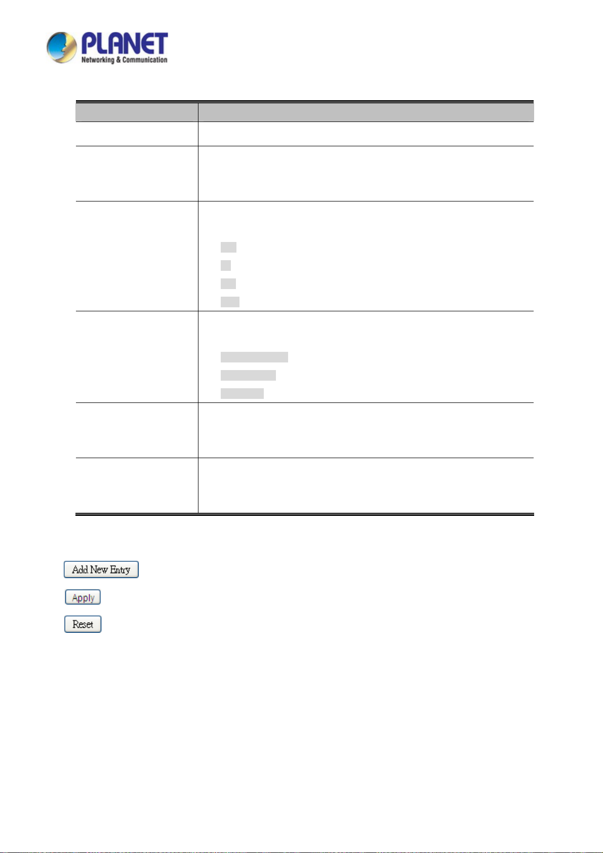
The page includes the following fields:
Object Description
User’s Manual of IGS-604HPT-M12
Delete
Group Name
Security Model
Security Level
Read View Name
Check to delete the entry. It will be deleted during the next save.
A string identifying the group name that this entry should belong to. The allowed
string length is 1 to 32, and the allowed content is the ASCII characters from 33
to 126.
Indicates the security model that this entry should belong to. Possible security
models are:
any: Accepted any security model (v1|v2c|usm).
v1: Reserved for SNMPv1.
v2c: Reserved for SNMPv2c.
usm: User-based Security Model (USM)
Indicates the security model that this entry should belong to. Possible security
models are:
NoAuth, NoPriv: None authentication and none privacy.
Auth, NoP riv: Authentication and none privacy.
Auth, Priv: Authentication and privacy.
The name of the MIB view defining the MIB objects for which this request may
Buttons
request the current values. The allowed string length is 1 to 32, and the allowed
content is the ASCII characters from 33 to 126.
Write View Name
: Click to add a new access entry.
: Click to apply changes
: Click to undo any changes made locally and revert to previously saved values.
The name of the MIB view defining the MIB objects for which this request may
potentially SET new values. The allowed string length is 1 to 32, and the allowed
content is the ASCII characters from 33 to 126.
91
Page 92
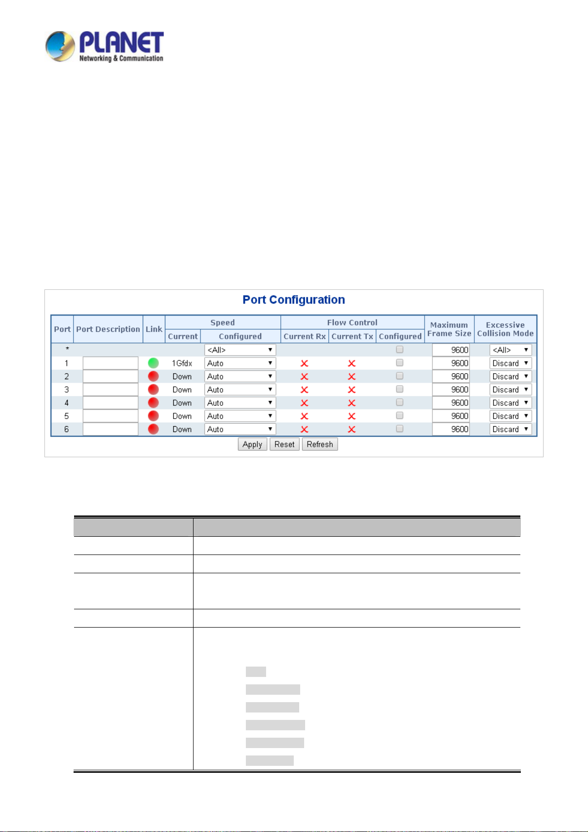
User’s Manual of IGS-604HPT-M12
4.4 Port Management
Use the Port Menu to display or configure the Industrial Managed Switch's ports. This section has the following items:
Port Configuration
Port Statistics Overview
Port Statistics Detail
Port Mirror
Configures port connection settings
Lists Ethernet and RMON port statistics
Lists Ethernet and RMON port statistics
Sets the source and target ports for mirroring
4.4.1 Port Configuration
This page displays current port configurations. Ports can also be configured here. The Port Configuration screen in Figure 4-4-1
appears.
The page includes the following fields:
Object Description
Port
Port Description
Link
Current Link Speed
Configured Link Speed
Figure 4-4-1: Port Configuration Screenshot
This is the logical port number for this row.
Indicates the per port description.
The current link state is displayed graphically. Green indicates the link is up and
red that it is down.
Provides the current link speed of the port.
Select any available link speed for the given switch port. Draw the menu bar to
select the mode.
Auto - Setup Auto negotiation for copper interface.
10Mbps HDX - Force sets 10Mbps/Half-Duplex mode.
10Mbps FDX - Force sets 10Mbps/Full-Duplex mode.
100Mbps HDX - Force sets 100Mbps/Half-Duplex mode.
100Mbps FDX - Force sets 100Mbps/Full-Duplex mode.
1Gbps FDX - Force sets 1000Mbps/Full-Duplex mode.
92
Page 93

User’s Manual of IGS-604HPT-M12
Disable - Shutdown the port manually.
Flow Control
Maximum Frame Size
Excessive Collision
Mode
When set each port to run at 100M Full, 100M Half, 10M Full, and 10M Half-speed modes. The
Auto-MDIX function will disable.
When Auto Speed is selected on a port, this section indicates the flow control
capability that is advertised to the link partner.
When a fixed-speed setting is selected, that is what is used. The Current Rx
column indicates whether pause frames on the port are obeyed, and the Current
Tx column indicates whether pause frames on the port are transmitted. The Rx
and Tx settings are determined by the result of the last Auto-Negotiation.
Check the configured column to use flow control. This setting is related to the
setting for Configured Link Speed.
Enter the maximum frame size allowed for the switch port, including FCS. The
allowed range is 1518 bytes to 10056 bytes.
Configure port transmit collision behavior.
Discard: Discard frame after 16 collisions (default).
Restart: Restart back off algorithm after 16 collisions.
Buttons
: Click to apply changes
: Click to undo any changes made locally and revert to previously saved values.
: Click to refresh the page. Any changes made locally will be undone.
93
Page 94

User’s Manual of IGS-604HPT-M12
4.4.2 Port Statistics Overview
This page provides an overview of general traffic statistics for all switch ports. The Port Statistics Overview screen in Figure
4-4-2 appears.
Figure 4-4-2: Port Statistics Overview Screenshot
The displayed counters are:
Object Description
Port
Packets
Bytes
Errors
Drops
Filtered
Buttons
: Download the Port Statistics Overview result as EXECL file.
The logical port for the settings contained in the same row.
The number of received and transmitted packets per port.
The number of received and transmitted bytes per port.
The number of frames received in error and the number of incomplete
transmissions per port.
The number of frames discarded due to ingress or egress congestion.
The number of received frames filtered by the forwarding process.
: Click to refresh the page immediately.
: Clears the counters for all ports.
: Print the Port Statistics Overview result.
Auto-refresh : Check this box to enable an automatic refresh of the page at regular intervals.
94
Page 95
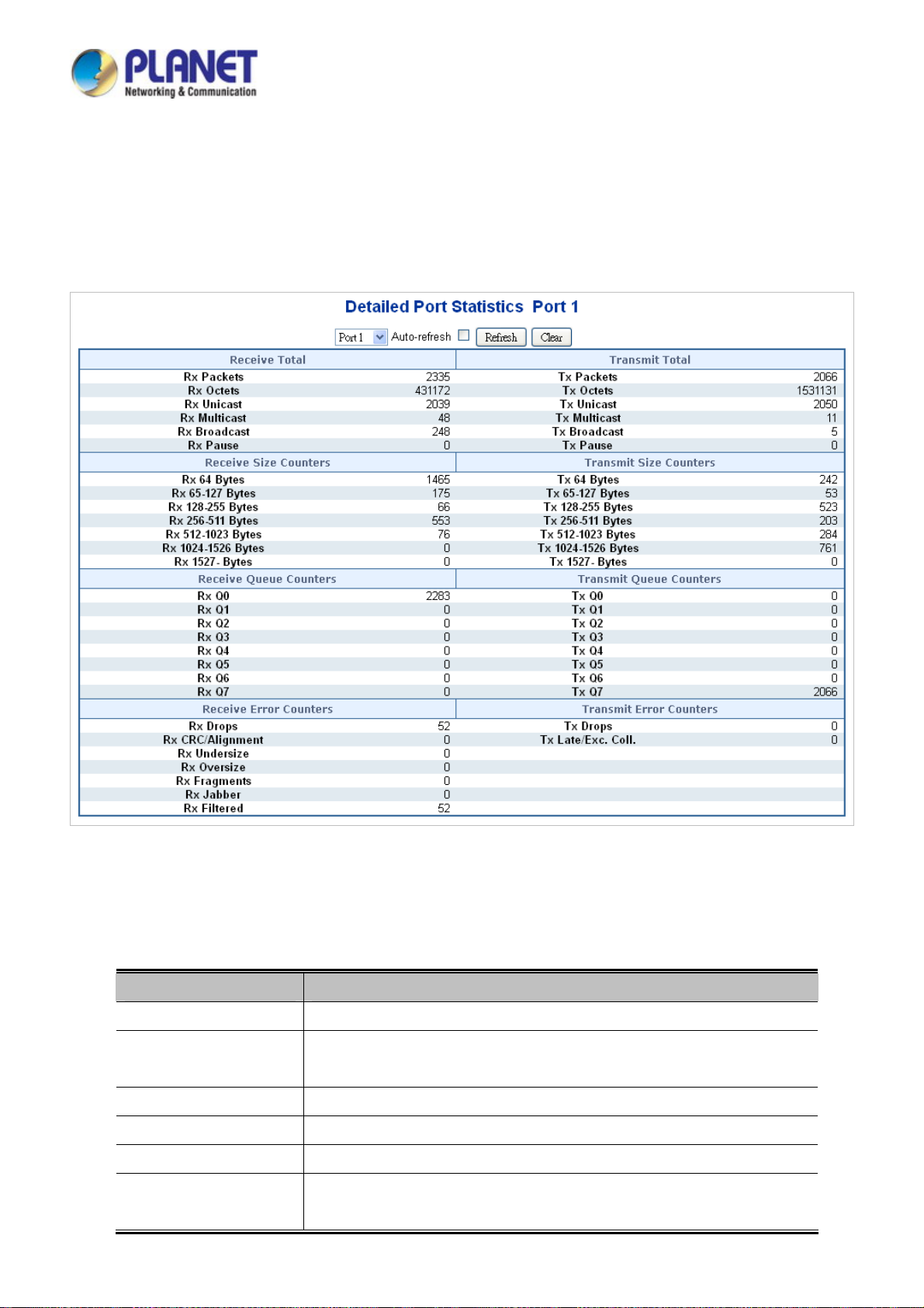
User’s Manual of IGS-604HPT-M12
4.4.3 Port Statistics Detail
This page provides detailed traffic statistics for a specific switch port. Use the port select box to select which switch port details
to display. The selected port belong to the currently selected stack unit, as reflected by the page header. The displayed counters
are the totals for receive and transmit, the size counters for receive and transmit, and the error counters for receive and transmit.
The Port Statistics Detail screen in Figure 4-4-3 appears.
Figure 4-4-3: Detailed Port Statistics Port 1 Screenshot
The page includes the following fields:
Receive Total and Transmit Total
Object Description
Rx and Tx Packets
Rx and Tx Octets
Rx and Tx Unicast
Rx and Tx Multicast
Rx and Tx Broadcast
Rx and Tx Pause
The number of received and transmitted (good and bad) packets
The number of received and transmitted (good and bad) bytes, including FCS,
but excluding framing bits.
The number of received and transmitted (good and bad) unicast packets.
The number of received and transmitted (good and bad) multicast packets.
The number of received and transmitted (good and bad) broadcast packets.
A count of the MAC Control frames received or transmitted on this port that has
an opcode indicating a PAUSE operation.
95
Page 96

User’s Manual of IGS-604HPT-M12
Receive and Transmit Size Counters
The number of received and transmitted (good and bad) packets split into categories based on their respective frame
sizes.
Receive and Transmit Queue Counters
The number of received and transmitted packets per input and output queue.
Receive Error Counters
Object Description
Rx Drops
Rx CRC/Alignment
Rx Undersize
Rx Oversize
Rx Fragments
Rx Jabber
Rx Filtered
1 Short frames are frames that are smaller than 64 bytes.
2 Long frames are frames that are longer than the configured maximum frame length for this port.
Transmit Error Counters
Object Description
The number of frames dropped due to lack of receive buffers or egress
congestion.
The number of frames received with CRC or alignment errors.
The number of short frames received with valid CRC.
The number of long frames received with valid CRC.
The number of short frames received with invalid CRC.
The number of long frames received with invalid CRC.
The number of received frames filtered by the forwarding process.
Tx Drops
Tx Late/Exc. Coll.
Buttons
: Click to refresh the page immediately.
: Clears the counters for all ports.
Auto-refresh : Check this box to enable an automatic refresh of the page at regular intervals.
The number of frames dropped due to output buffer congestion.
The number of frames dropped due to excessive or late collisions.
96
Page 97

User’s Manual of IGS-604HPT-M12
4.4.4 Port Mirror
Configure port Mirroring on this page. This function provides monitoring network traffic that forwards a copy of each incoming or
outgoing packet from one port of a network Switch to another port where the packet can be studied. It enables the manager to
keep close track of switch performance and alter it if necessary.
To debug network problems, selected traffic can be copied, or mirrored to a mirror port where a frame analyzer can be
attached to analyze the frame flow.
The Industrial Managed Switch can unobtrusively mirror traffic from any port to a monitor port. You can then attach a
protocol analyzer or RMON probe to this port to perform traffic analysis and verify connection integrity.
Figure 4-4-4: Port Mirror Application
The traffic to be copied to the mirror port is selected as follows:
All frames received on a given port (also known as ingress or source mirroring).
All frames transmitted on a given port (also known as egress or destination mirroring).
Mirror Port Configuration
The Port Mirror screen in Figure 4-4-5 appears.
97
Page 98

User’s Manual of IGS-604HPT-M12
The page includes the following fields:
Object Description
Port to mirror on
Port
Mode
For a given port, a frame is only transmitted once. It is therefore not possible to mirror Tx frames on
Figure 4-4-5: Mirror Configuration Screenshot
Frames from ports that have either source (rx) or destination (tx) mirroring enabled are
mirrored to this port. Disabled disables mirroring.
The logical port for the settings contained in the same row.
Select mirror mode.
■ Rx only: Frames received at this port are mirrored to the mirroring port. Frames
transmitted are not mirrored.
■ Tx only: Frames transmitted from this port are mirrored to the mirroring port. Frames
received are not mirrored.
■ Disabled: Neither frames transmitted or frames received are mirrored.
■ Both: Frames received and frames transmitted are mirrored to the mirror port.
Buttons
the mirror port. Because of this, mode for the selected mirror port is limited to Disabled or Rx only.
: Click to apply changes
: Click to undo any changes made locally and revert to previously saved values.
98
Page 99

User’s Manual of IGS-604HPT-M12
4.5 Link Aggregation
Port Aggregation optimizes port usage by linking a group of ports together to form a single Link Aggregated Groups (LAGs). Port
Aggregation multiplies the bandwidth between the devices, increases port flexibility, and provides link redundancy.
Each LAG is composed of ports of the same speed, set to full-duplex operations. Ports in a LAG, can be of different media types
(UTP/Fiber, or different fiber types), provided they operate at the same speed.
Aggregated Links can be assigned manually (Port Trunk) or automatically by enabling Link Aggregation Control Protocol
(LACP) on the relevant links.
Aggregated Links are treated by the system as a single logical port. Specifically, the Aggregated Link has similar port attributes
to a non-aggregated port, including auto-negotiation, speed, Duplex setting, etc.
The device supports the following Aggregation links :
Static LAGs (Port Trunk) – Force aggregared selected ports to be a trunk group.
Link Aggregation Control Protocol (LACP) LAGs - LACP LAG negotiate Aggregated Port links with other LACP
ports located on a different device. If the other device ports are also LACP ports, the devices establish a LAG
between them.
Figure 4-5-1: Link Aggregation
99
Page 100

User’s Manual of IGS-604HPT-M12
The Link Aggregation Control Protocol (LACP) provides a standardized means for exchanging information between Partner
Systems that require high speed redundant links. Link aggregation lets you group up to eight consecutive ports into a single
dedicated connection. This feature can expand bandwidth to a device on the network. LACP operation requires full-duplex mode,
more detail information refer to the IEEE 802.3ad standard.
Port link aggregations can be used to increase the bandwidth of a network connection or to ensure fault recovery. Link
aggregation lets you group up to 4 consecutive ports into a single dedicated connection between any two the Switch or other
Layer 2 switches. However, before making any physical connections between devices, use the Link aggregation Configuration
menu to specify the link aggregation on the devices at both ends. When using a port link aggregation, note that:
The ports used in a link aggregation must all be of the same media type (RJ45, 100 Mbps fiber).
The ports that can be assigned to the same link aggregation have certain other restrictions (see below).
Ports can only be assigned to one link aggregation.
The ports at both ends of a connection must be configured as link aggregation ports.
None of the ports in a link aggregation can be configured as a mirror source port or a mirror target port.
All of the ports in a link aggregation have to be treated as a whole when moved from/to, added or deleted from a VLAN.
The Spanning Tree Protocol will treat all the ports in a link aggregation as a whole.
Enable the link aggregation prior to connecting any cable between the switches to avoid creating a data loop.
Disconnect all link aggregation port cables or disable the link aggregation ports before removing a port link aggregation to
avoid creating a data loop.
It allows a maximum of 10 ports to be aggregated at the same time. The Industrial Managed Switch support Gigabit Ethernet
ports (up to 5 groups). If the group is defined as a LACP static link aggregation group, then any extra ports selected are placed
in a standby mode for redundancy if one of the other ports fails. If the group is defined as a local static link aggregation group,
then the number of ports must be the same as the group member ports.
The aggregation code ensures that frames belonging to the same frame flow (for example, a TCP connection) are always
forwarded on the same link aggregation member port. Recording of frames within a flow is therefore not possible. The
aggregation code is based on the following information:
Source MAC
Destination MAC
Source and destination IPv4 address.
Source and destination TCP/UDP ports for IPv4 packets
Normally, all 5 contributions to the aggregation code should be enabled to obtain the best traffic distribution among the link
aggregation member ports. Each link aggregation may consist of up to 10 member ports. Any quantity of link aggregation s may
be configured for the device (only limited by the quantity of ports on the device.) To configure a proper traffic distribution, the
ports within a link aggregation must use the same link speed.
100
 Loading...