

Page 1

Industrial IP67-rated 6-Port Gigabit
Managed Ethernet Switch
(-40~75 degrees C)
IGS-5227-6T/IGS-5227-6MT/IGS-5227-6MT-X
Quick Installation Guide
Page 2

Table of Contents
1. Package Contents ....................................................................................... 3
2. Making Waterproof RJ45 Cable (IGS-5227-6T) .............................................. 4
3. Connecting Waterproof Cable to the IGS-5227-6T ......................................... 7
4. M12 A-coded Connector Pin Assignment ......................................................10
5. M12 (8-pin, A-coded Male) to RJ45 (8-pin) Straight-through UTP Cabling .......11
6. M12 X-coded Connector Pin Assignment ......................................................12
7. M12 (8-pin, X-coded Male) to RJ45 (8-pin) Straight-through UTP Cabling .......13
8. Connecting M12 Cable to the IGS-5227-6MT/IGS-5227-6MT-X .......................14
9. M12 DC Power Cable Pin Assignment .........................................................16
10. Requirements ...........................................................................................17
11. Starting Web Management .........................................................................18
12. Saving Conguration via Web .....................................................................21
13. Recovering Back to Default Conguration .................................................... 22
14. Customer Support .....................................................................................23
Page 3

1. Package Contents
Thank you for purchasing PLANET Industrial L2+ Managed Ethernet Switch.
“Industrial Managed Switch” is used as an alternative name in this Quick
Installation Guide. Open the box of the Industrial Managed Switch and carefully
unpack it. The box should contain the following items:
z The Industrial Managed Switch
(IGS-5227-6T/IGS-5227-6MT/IGS-5227-6MT-X) x 1
z Quick Installation Guide x 1
z 1.2m M12 Power Cable x 1
z Waterproof RJ45 Connector (IGS-5227-6T only) x 6
z 2m 8-pin A-coded M12-to-RJ45 UTP Cable (IGS-5227-6MT only) x 1
z 2m 8-pin X-coded M12-to-RJ45 UTP Cable (IGS-5227-6MT-X only) x 1
z DIN Rail Kit x 1
z Wall-mount Kit x 1
If any item is found missing or damaged, please contact your local reseller for
replacement.
3
Page 4
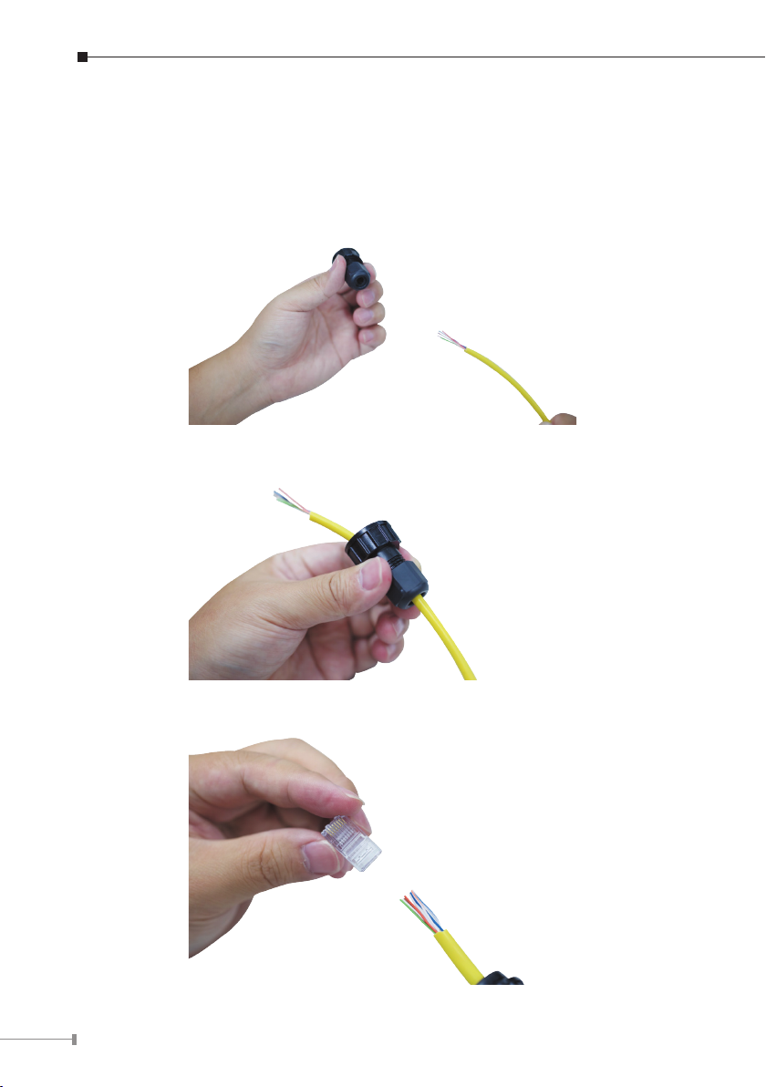
2. Making Waterproof RJ45 Cable (IGS-5227-6T)
Please read the following instructions and follow the procedures in the order being
presented:
Step 1: Take a waterproof RJ45 jack out from the Industrial Managed Switch box
and get hold of one RJ45 cable.
Step 2: Insert the RJ45 cable through the waterproof RJ45 jack.
Step 3: Prepare an RJ45 connector.
4
Page 5
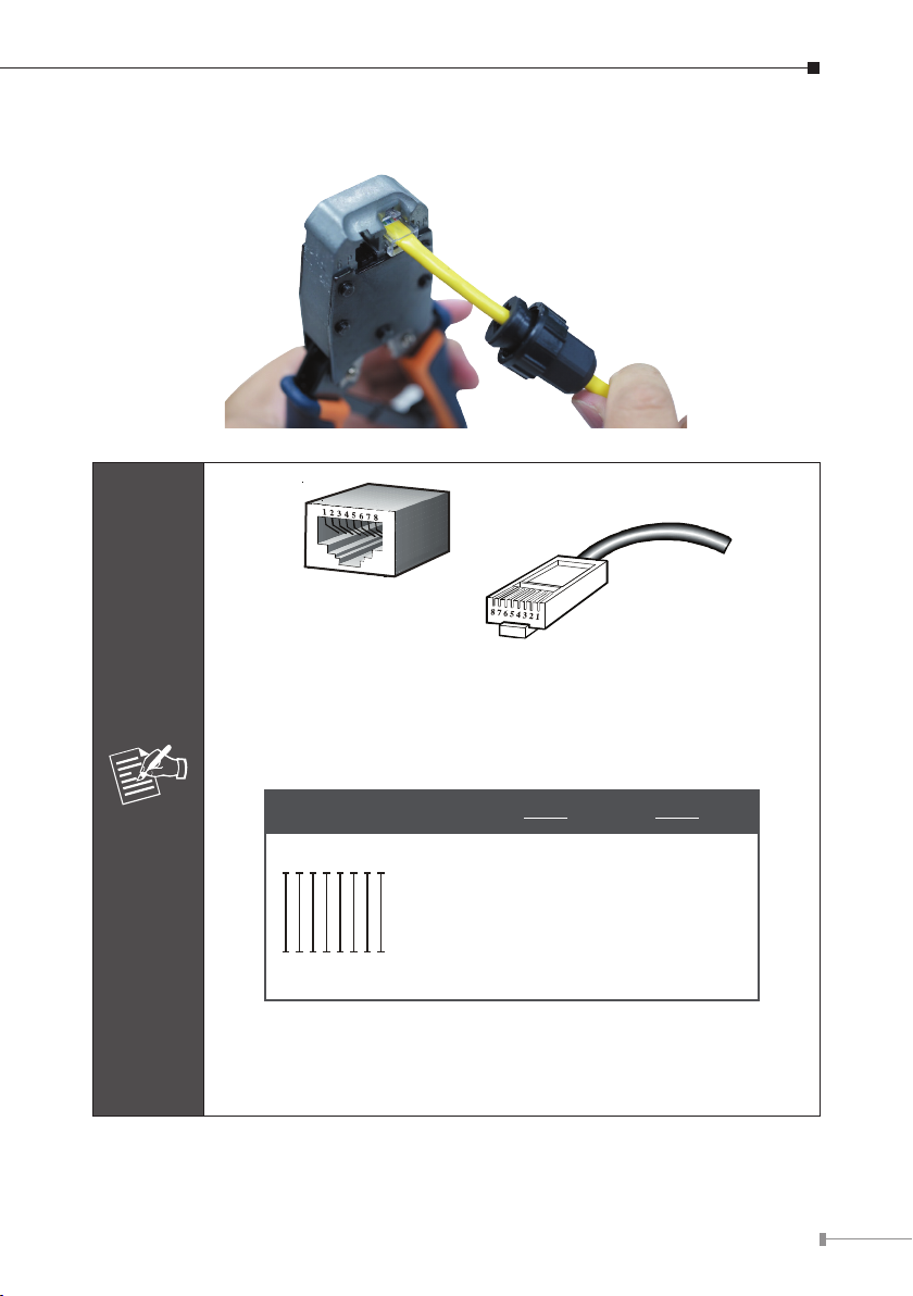
Step 4: Put the RJ45 connector in place with cable crimper.
The standard RJ45 receptacle/connector
There are 8 wires on a standard UTP/STP cable and each wire is
color-coded. The following shows the pin allocation and colors of
straight-through cable connection:
Note
Straight Cable
112233445566778
SIDE 1
SIDE 1
SIDE 2
8
1 = White/Orange
2 = Orange
3 = White/Green
4 = Blue
5 = White/Blue
6 = Green
7 = White/Brown
8 = Brown
SIDE 2
1 = White/Orange
2 = Orange
3 = White/Green
4 = Blue
5 = White/Blue
6 = Green
7 = White/Brown
8 = Brown
Please make sure your waterproof RJ45 cables are with same pin
assignment and colors as the above picture before deploying the
cables into your network.
5
Page 6
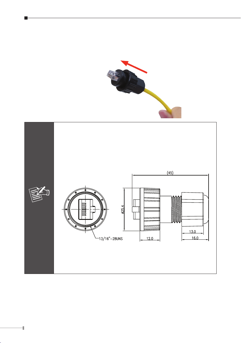
Step 5: To lock in the RJ45 connector, pull back the cable till the connector nicely
ts into the waterproof connector hole.
1. Use only the waterproof RJ45 connector provided in the package
of the IGS-5227-6T.
2.If the waterproof RJ45 connector is found missing or damaged,
please contact your local reseller where you purchased from. If
the new waterproof RJ45 connector is obtained from PLANET,
make sure its dimensions are the same.
6
Note
3. Never use any waterproof RJ45 connector that is not purchased
from PLANET or doesn’t have the same dimensions of the IGS5227-6T; it will damage the device permanently.
Page 7
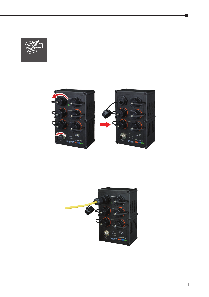
3. Connecting Waterproof Cable to the IGS-5227-6T
Follow all the connecting waterproof cable steps as shown in the
example.
Note
Step 1: Turn counterclockwise to remove the waterproof screw nuts of a RJ45
port and power input.
Step 2: Insert the waterproof RJ45 connector into the port of the Industrial
Managed Switch.
7
Page 8

Step 3: Turn clockwise to tighten the screw nut of the waterproof RJ45 connector.
Step 4: Insert the waterproof M12 power connector into the port of the power
input.
8
Page 9

Step 5: Turn clockwise to tighten the screw nut of the waterproof M12 power
connector.
1. Make sure to tightly close all interfaces to have waterproof effect.
2. Before connecting the DC power cord, please check whether your
Note
local DC power source is stable.
9
Page 10

4. M12 A-coded Connector Pin Assignment
The IGS-5227-6MT front panel provides six 10/100/1000BASE-T Ethernet ports
in the form of M12 8-pin A-coded female connector. These ports are designed
for Ethernet equipment connection through Cat5/5e UTP cables. The M12 8-pin
A-coded input interface pinout is shown below:
Pin Con
12
73
4
6
8
5
8-pin M12 A-coded Female 10/100/1000T Connector Pin Assignment
1 DA+
2 DA
3 DB+
4 DC+
5 DC
6 DB
7 DD+
8 DD
10
Page 11

5. M12 (8-pin, A-coded Male) to RJ45 (8-pin) Straight-
through UTP Cabling
M12 A-code Male
Connector Pin No.
1 BI_DA+ white/orange 1
2 BI_DA- orange 2
3 BI_DB+ white/green 3
4 BI_DC+ blue 4
5 BI_DC- white/blue 5
6 BI_DB- green 6
7 BI_DD+ white/brown 7
8 BI_DD- brown 8
As each Ethernet port of the Industrial Managed Switch is running
in auto negotiation mode, make sure the Ethernet ports of the
corresponding Ethernet devices are also running in auto negotiation
Note
mode, otherwise, the Ethernet performance will be poor.
MDI
1000BASE-T Signal ID
T568B Color
RJ45 Connector
Pin No.
11
Page 12

6. M12 X-coded Connector Pin Assignment
The IGS-5227-6MT-X front panel provides six 10/100/1000BASE-T Ethernet ports
in the form of M12 8-pin X-coded female connector. These ports are designed
for Ethernet equipment connection through Cat5/5e UTP cables. The M12 8-pin
X-coded input interface pinout is shown below:
6
7
5
8
Pin Con
1 DA+
2 DA
4
3
8-pin M12 X-coded Female 10/100/1000T Connector Pin Assignment
1
2
3 DB+
DB4
5
DD+
6
DD
7
8
DC
DC+
12
Page 13

7. M12 (8-pin, X-coded Male) to RJ45 (8-pin) Straight-
through UTP Cabling
M12 X-code Male
Connector Pin No.
1 BI_DA+ white/orange 1
2 BI_DA- orange 2
3 BI_DB+ white/green 3
4 BI_DB- green 6
5 BI_DD+ white/brown 7
6 BI_DD- brown 8
7 BI_DC- White/blue 5
8 BI_DC+ blue 4
As each Ethernet port of the Industrial Managed Switch is running
in auto negotiation mode, make sure the Ethernet ports of the
Note
corresponding Ethernet devices are also running in auto negotiation
mode, otherwise, the Ethernet performance will be poor.
MDI
1000BASE-T Signal ID
T568B Color
RJ45 Connector
Pin No.
13
Page 14

8. Connecting M12 Cable to the IGS-5227-6MT/
IGS-5227-6MT-X
Follow all the connecting M12 cable to the IGS-5227-6MT/IGS-
Note
Step 1: Turn counterclockwise to remove the waterproof screw nuts of an M12
Step 2: Insert the M12 UTP male connector into the M12 female Gigabit Ethernet
5227-6MT-X steps as shown in the example.
connector and power input.
port of the Industrial Managed Switch.
Step 3: Turn clockwise to tighten the screw nut of the M12 connector and make
sure the connection is tight.
14
Page 15

Step 4: Insert the M12 power female connector into the M12 male port of the
power input.
Step 5: Turn clockwise to tighten the screw nut of the M12 power connector.
Note
Note
Before connecting the DC power cord, please check whether your
local DC power source is stable.
Make sure to tightly close all interfaces to have waterproof
effect.
15
Page 16

9. M12 DC Power Cable Pin Assignment
The front panel of the Industrial Managed Switch provides one M12 DC power
5-pin male connector for DC power input. Please use the power cable with the M12
DC power 5-pin female connector from the Industrial Managed Switch package for
DC power input. The M12 DC power cable pin assignment is shown below:
M12 DC power cable pin assignment and wiring code
V1 positive (+) pin = black cable
V1 negative (-) pin = brown cable
V2 positive (+) pin = blue cable
16
Note
V2 negative (-) pin = white cable
A. Make sure you connect the correct power pin to your DC power
source.
1. The wire gauge for the power cable should be in the range of
12 ~ 24 AWG.
2. The DC power input range is 12 ~ 48V DC.
B. There are two methods to install the Industrial Managed Switch
– DIN-rail mounting and wall-mount plate mounting. For more
detailed information, please refer to Chapter 2 of the user’s
manual.
Page 17

10. Requirements
Workstations running Windows XP/2003/Vista/7/8/10/2008, MAC OS X or later,
Linux, UNIX, or other platforms are compatible with TCP/IP Protocols.
Workstations are installed with Ethernet NIC (Network Interface Card)
Ethernet Port Connection
z Network cables -- Use standard network (UTP) cables with RJ45 connectors.
z The above PC is installed with Web browser and JAVA runtime environment plug-
in.
It is recommended to use Internet Explore 8.0 or above to access
the Industrial Managed Switch. If the Web interface of the Indus-
Note
trial Managed Switch is not accessible, please turn off the anti-virus
software or firewall and then try it again.
17
Page 18

11. Starting Web Management
with Web Browser
The following shows how to start up the Web Management of the Industrial
Managed Switch. Note the Industrial Managed Switch is congured through an
Ethernet connection. Please make sure the manager PC must be set on the same
IP subnet address.
For example, the default IP address of the Industrial Managed Switch is
192.168.0.100, then the manager PC should be set at 192.168.0.x (where x
is a number between 1 and 254, except 100), and the default subnet mask is
255.255.255.0.
PC / Workstation
192.168.0.x
Industrial
Managed Switch
RJ45/UTP Cable
IP Address:
192.168.0.100
Figure 11-1: IP Management Diagram
18
Page 19

Logging in to the Industrial Managed Switch
1. Use Internet Explorer 8.0 or above Web browser and enter IP address
http://192.168.0.100 (default IP address) to access the Web interface.
2. When the following dialog box appears, please enter the default user name and
password “admin”. The login screen in Figure 11-2 appears.
Default Username: admin
Default Password: admin
Figure 11-2: Login Screen
3. After entering the password, the main screen appears as Figure 11-3 shows.
Figure 11-3: Web Main Screen of Industrial Managed Switch
19
Page 20

The Switch Menu on the left of the Web page lets you access all the commands
and statistics the Industrial Managed Switch provides.
Figure 11-4: Switch Menu
If you are not familiar with Switch functions or the related parameter, press “Help icon” anytime on the Web page to get the help
Note
description.
Now, you can use the Web management interface to continue the Switch
management. Please refer to the user’s manual for more details.
20
Page 21

12. Saving Conguration via Web
In the Industrial Managed Switch, the running conguration le is stored in the
RAM. In the current version, the running conguration sequence of running-
cong can be saved from the RAM to FLASH by executing save startup cong
command, so that the running conguration sequence becomes the startup
conguration le, which is called conguration save.
To save all applied changes and set the current conguration as a startup
conguration, the startup-conguration le will be loaded automatically across a
system reboot.
1. Click System, Save Startup Cong.
2. Press the “Save Conguration” button.
21
Page 22

13. Recovering Back to Default Conguration
IP address has been changed or admin password has been forgotten –
Follow all the recovering back to default configuration steps as
Note
1. Power off the Industrial Managed Switch and remove all the existing connections.
2. Use the straight RJ45 cable to connect to port 1 and port 2 in the loop topology
as shown below:
shown in the example.
3. Power on the Industrial Managed Switch and 6 LNK/ACT LEDs will be lit.
4. Resetting Industrial Managed Switch to the factory default is done when 6 LNK/
ACT LEDs are lit again.
5. Remove the RJ45 cable from port 1 and port 2.
6. Reset the Industrial Managed Switch to Factory Default conguration. The Industrial Managed Switch will then reboot and load the default settings as shown
below:
Default Username: admin
Default Password: admin
Default IP Address: 192.168.0.100
Default Subnet Mask: 255.255.255.0
Default Gateway: 192.168.0.254
22
Page 23

14. Customer Support
Thank you for purchasing PLANET products. You can browse our online FAQ
resource and User’s Manual on PLANET Web site rst to check if it could solve your
issue. If you need more support information, please contact PLANET switch support
team.
PLANET online FAQ:
http://www.planet.com.tw/en/support/faq.php?type=1
Switch support team mail address:
support_switch@planet.com.tw
IGS-5227-6T/IGS-5227-6MT/IGS-5227-6MT-X User’s Manual:
http://www.planet.com.tw/en/support/download.php?type1=22153&model=&type=3
(Please select your switch model name from the drop-down menu of Product
Models.)
Copyright © PLANET Technology Corp. 2017.
Contents are subject to revision without prior notice.
PLANET is a registered trademark of PLANET Technology Corp. All other trademarks belong to their
respective owners.
23
Page 24

 Loading...