

Page 1

5-/8-Port 10/100/1000Mbps
Industrial Gigabit Ethernet Switch
IGS-501T/IGS-801T
User's Manual
Page 2

Table of Contents
1. Package Contents ...................................................................... 3
2. Hardware Introduction ............................................................... 4
2.1 Physical Dimensions ............................................................ 4
2.2 Switch Front Panel .............................................................. 6
2.3 LED Indicators .................................................................... 7
2.4 Switch Upper Panel ............................................................. 8
2.5 Wiring the Power Inputs ...................................................... 8
2.6 Wiring the Fault Alarm Contact ............................................ 9
2.7 ProductSpecications ........................................................10
3. Installation ..............................................................................12
3.1 DIN-rail Mounting Installation .............................................12
3.2 Wall-mount Plate Mounting .................................................13
4. Troubleshooting ........................................................................15
5. Customer Support ....................................................................16
APPENDIX A: Networking Connection ...............................................17
A.1 Switch’s RJ45 Pin Assignments ............................................17
A.2 RJ45 Cable Pin Assignments ................................................18
Page 3
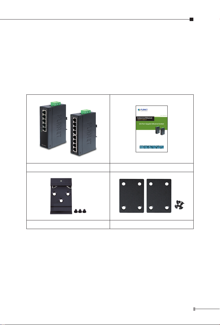
1. Package Contents
Thank you for purchasing PLANET 5-/8-Port 10/100/1000T industrial
Gigabit Ethernet Switch, IGS-501T and IGS-801T. In the following
section, the term “Industrial Gigabit Ethernet Switch” means the
IGT-501T/IGT-801T.
Open the box of the Industrial Gigabit Ethernet Switch and carefully
unpack it. The box should contain the following items:
Industrial Gigabit Ethernet Switch x 1 User's Manual x 1
DIN Rail Kit x 1 Wall-mount Kit x 1
If any of these are missing or damaged, please contact your dealer
immediately; if possible, retain the carton including the original packing
material, and use them again to repack the product in case there is a
need to return it to us for repair.
3
Page 4
2. Hardware Introduction
Rear View
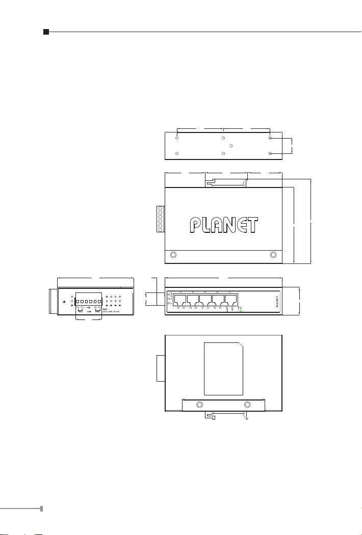
2.1 Physical Dimensions
IGS-501T dimensions (W x D x H): 135 x 87 x 32mm
53.50 53.50
Top View
48.8046.50 39.70
18.00
87.80
97.10
Side View
87.80
30.00
9.20
15.20
Front View
135.00
Bottom View
32.00
Dimensions ( unit = mm )
4
Page 5
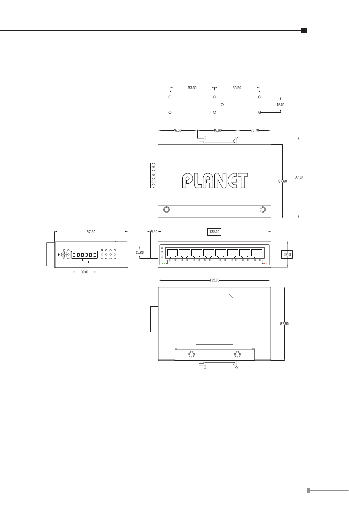
IGS-801T dimensions (W x D x H): 135 x 87 x 32mm
Dimensions ( unit = mm )
Rear View
Top View
Side View
V1+ V1- V2+ V2-
PWR1
PWR2Fault
Input
DC12~48V, AC 24V
P1 P2 FAULT
ACT
LNK
1000
Front View
1
2
3
4
5
6
7
8
IGS-801T
ACT
LNK
100
Bottom View
5
Page 6
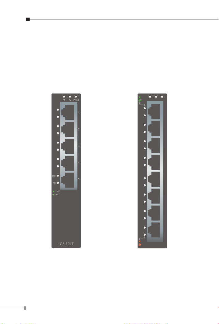
2.2 Switch Front Panel
The front panel of the Industrial Gigabit Ethernet Switch consists of
5 or 8 auto-sensing 10/100/1000Mbps Ethernet RJ45 ports. The LED
Indicators are also located on the RJ45 ports of the Gigabit Ethernet
Switch.
Figures 2-1 and 2-2 show the front panels of Industrial Gigabit
Ethernet Switches.
LNK
P1 P2 FAULT
ACT
1000
1
2
3
4
5
6
7
100
LNK
ACT
8
IGS-801T
Figure 2-1: IGS-501T Front Panel Figure 2-2: IGS-801T Front Panel
6
Page 7

2.3 LED Indicators
IGS-501T:
LED Color Function
P1 Green Lit: indicates power 1 has power.
P2 Green Lit: indicates power 2 has power.
FAULT Green Lit: indicates either power 1 or power 2 has no power.
Lit: indicates the port is successfully connecting to
the network at 1000Mbps.
1000 Green
100 Green
IGS-801T:
LED Color Function
P1 Green Lit: indicates power 1 has power.
P2 Green Lit: indicates power 2 has power.
FAULT Red Lit: indicates either power 1 or power 2 has no power.
1000 Green
100 Orange
Off: indicates that the port is successfully connecting
to the network at 10Mbps or 100Mbps.
Blinking: indicates that the port is actively sending
or receiving data.
Lit: indicates the port is successfully connecting to
the network at 100Mbps or 10Mbps.
Off: indicates that the port is successfully connecting
to the network at 1000Mbps.
Blinking: indicates that the port is actively sending
or receiving data.
Lit: indicates the port is successfully connecting to
the network at 1000Mbps.
Off: indicates that the port is successfully connecting
to the network at 10Mbp or 100Mbps.
Blinking: indicates that the port is actively sending
or receiving data.
Lit: indicates the port is successfully connecting to
the network at 100Mbps or 10Mbps.
Off: indicates that the port is successfully connecting
to the network at 1000Mbps.
Blinking: indicates that the port is actively sending
or receiving data.
7
Page 8

2.4 Switch Upper Panel
The upper panel of the Industrial Gigabit Ethernet Switch consists of
one terminal block connector within two DC power inputs.
Figure 2-3 shows the upper panel of the Industrial Gigabit Ethernet
Switch.
Figure 2-3: Industrial Gigabit Ethernet Switch Upper Panel
2.5 Wiring the Power Inputs
The 6-contact terminal block connector on the top panel of Industrial
Gigabit Ethernet Switch is used for two DC redundant power inputs.
Please follow the steps below to insert the power wire.
1. Insert positive and negative DC power wires into contacts 1 and 2
for Power 1 or 5, and 6 for Power 2.
V1+ V1- V2+ V2-
8
Page 9

2. Tighten the wire-clamp screws for preventing the wires from loosening.
1 2 3 4 5 6
Power 1 Fault Power 2
+ - + -
1 The wire gauge for the terminal block should be in the
range between 12 and 24 AWG.
Note
2. The device must be grounded.
3. The DC power input range is 12V ~ 48V DC.
2.6 Wiring the Fault Alarm Contact
The fault alarm contacts are in the middle of the terminal block
connector as the picture shows below. Inserting the wires, the
Industrial Gigabit Ethernet Switch will detect the fault status of the
power failure and then forms an open circuit. The following illustration
shows an application example for wiring the fault alarm contacts.
Insert the wires into the fault alarm contacts
9
Page 10

1. The wire gauge for the terminal block should be in the
range between 12 and 24 AWG.
2. Alarm relay circuit accepts up to 30V, max. 3A
Note
currents.
Fault Alarm Contacts
Fault
The Fault Alarm Contacts are
energized (CLOSE) for normal
operation and will OPEN when
failure occurs
2.7 Product Specications
Model IGS-501T IGS-801T
HardwareSpecications
10/100/1000BASE-T
Ports
Dimensions
(W x D x H)
Weight 498g 461g
12~48V DC, redundant power with polarity
Power Requirements
reverse protection function, 24V AC power
support
Power Consumption/
Dissipation
5.28 watts/18BTU 6.72 watts/23BTU
Installation DIN rail kit and wall-mount ear
SwitchSpecications
Switch Processing
Scheme
5 8
135 x 87 x 32 mm
Store-and-Forward
10
Page 11

Address Table 2K 4K
Buffer 1M bits
Flow Control
Switch Fabric 10Gbps 16Gbps
Throughput
(packet per second)
Jumbo Frame 9K
Network Cables
Standards Conformance
Standards
Compliance
Temperature
Humidity
Regulatory
Compliance
Back pressure for half duplex
IEEE 802.3x pause frame for full duplex
7.4Mpps 11.9Mpps
10/100/1000BASE-T:
Cat3, 4, 5, 5e, 6 UTP cable (100 meters, max.)
EIA/TIA-568 100-ohm STP (100 meters, max.)
IEEE 802.3 Ethernet
IEEE 802.3u Fast Ethernet
IEEE 802.3ab Gigabit Ethernet
IEEE 802.3x Full-Duplex Flow Control
Operating: -40~75 degrees C
Storage: -40~75 degrees C
Operating: 5% to 95%, Storage: 5% to 95%
(non-condensing)
FCC Part 15 Class A, CE
1.5Mbits SRAM packet
buffer
11
Page 12

3. Installation
3.1 DIN-rail Mounting Installation
The DIN-rail is screwed on the Industrial Gigabit Ethernet Switch when
out of factory. When you need to replace the wall-mount application
with DIN-rail application on Industrial Gigabit Ethernet Switch, please
refer to the following gures to screw the DIN-rail on the Industrial
Gigabit Ethernet Switch. To hang the Industrial Gigabit Ethernet Switch,
follow the steps below:
Step 1: Screw the DIN-rail on the Industrial Gigabit Ethernet Switch.
Step 2: Place the bottom of DIN-rail lightly into the track.
12
Page 13

Step 3: Check whether the DIN-rail is tightly on the track.
Step 4: Please refer to the following procedure to remove the
Industrial Gigabit Ethernet Switch from the track.
Step 5: Lightly pull out the bottom of DIN-rail to remove it from the
track.
13
Page 14

3.2 Wall-mount Plate Mounting
To install the Industrial Gigabit Ethernet Switch on the wall, please
follow the instructions described below.
Step 1: Remove the DIN-rail from the Industrial Gigabit Ethernet
Switch; loosen the screws to remove the DIN-rail.
Step 2: Place the wall-mount plate on the rear panel of the Industrial
Gigabit Ethernet Switch.
Step 3: Use the screws to screw the wall-mount plate on the
Industrial Gigabit Ethernet Switch.
Step 4: Use the hook holes at the corners of the wall-mount plate to
hang the Industrial Gigabit Ethernet Switch on the wall.
Step 5: To remove the wall-mount plate, reverse the steps above.
14
Page 15

4. Troubleshooting
This chapter contains information to help you solve issues. If the
Industrial Gigabit Ethernet Switch is not functioning properly, make
sure the Industrial Gigabit Ethernet Switch was set up according to
instructions in this manual.
The per port LED is not lit
Solution:
Check the cable connection of the Industrial Gigabit Ethernet Switch.
Performance is bad
Solution:
Check the speed duplex mode of the partner device. The Industrial
Gigabit Ethernet Switch is run in auto-negotiation mode and if the
partner is set to half duplex, then the performance will be poor.
Per port LED is lit, but the trafc is irregular
Solution:
Check that the attached device is not set to dedicate full duplex. Some
devices use a physical or software switch to change duplex modes.
Auto-negotiation may not recognize this type of full-duplex setting.
Why the Industrial Gigabit Ethernet Switch doesn’t connect to
the network
Solution:
Check per port LED on the Industrial Gigabit Ethernet Switch. Try
another port on the Industrial Gigabit Ethernet Switch. Make sure the
cable is installed properly. Make sure the cable is the right type. Turn
off the power. After a while, turn on the power again.
15
Page 16

5. Customer Support
Thank you for purchasing PLANET products. You can browse our online
FAQresource andUser’sManual on PLANET Web site rst to check if it
could solve your issue. If you need more support information, please
contact PLANET switch support team.
PLANET online FAQ:
http://www.planet.com.tw/en/support/faq.php?type=1
Switch support team mail address:
support_switch@planet.com.tw
Copyright © PLANET Technology Corp. 2016.
Contents are subject to revision without prior notice.
PLANET is a registered trademark of PLANET Technology Corp. All other trademarks
belong to their respective owners.
16
Page 17

APPENDIX A: Networking Connection
A.1 Switch’s RJ45 Pin Assignments
1000Mbps, 1000BASE-T
Contact MDI MDI-X
1 BI_DA+ BI_DB+
2 BI_DA- BI_DB-
3 BI_DB+ BI_DA+
4 BI_DC+ BI_DD+
5 BI_DC- BI_DD-
6 BI_DB- BI_DA-
7 BI_DD+ BI_DC+
8 BI_DD- BI_DC-
10/100Mbps, 10/100BASE-TX
RJ45 Connector pin assignment
MDI
Contact
1 Tx + (transmit) Rx + (receive)
2 Tx - (transmit) Rx - (receive)
3 Rx + (receive) Tx + (transmit)
4, 5 Not used
6 Rx - (receive) Tx - (transmit)
7, 8 Not used
Media Dependent
Interface
Media Dependent
Interface-Cross
MDI-X
17
Page 18

EC Declaration of Conformity
For the following equipment:
*Type of Product : 5-/8-Port 10/100/1000Mbps Industrial Ethernet Switch
*Model Number : IGS-501T, IGS-801T
* Produced by:
Manufacturer‘s Name : Planet Technology Corp.
Manufacturer‘s Address : 10F., No.96, Minquan Rd., Xindian Dist.,
New Taipei City 231, Taiwan (R.O.C.)
is herewith confirmed to comply with the requirements set out in the Council Directive on the
Approximation of the Laws of the Member States relating to Electromagnetic Compatibility
Directive on (2004/108/EC).
For the evaluation regarding the EMC, the following standards were applied:
EN 55022 (2010+AC: 2011)
EN 61000-3-2 (2006+A1:2009+A2:2009)
EN 61000-3-3 (2008)
EN 55024 (2010)
IEC 61000-4-2 (2009)
IEC 61000-4-3 (2006 + A1:2008 + A2 :2010)
IEC 61000-4-4 (2010)
IEC 61000-4-5 (2006)
IEC 61000-4-6 (2009)
IEC 61000-4-8 (2010)
IEC 61000-4-11 (2004)
Responsible for marking this declaration if the:
Manufacturer Authorized representative established within the EU
Authorized representative established within the EU (if applicable):
Company Name: Planet Technology Corp.
Company Address: 10F., No.96, Minquan Rd., Xindian Dist., New Taipei City 231, Taiwan
(R.O.C.)
Person responsible for making this declaration
Name, Surname Kent Kang
Position / Title : Product Manager
Taiwan 21, April, 2014
Place Date Legal Signature
PLANET TECHNOLOGY CORPORATION
e-mail: sales@planet.com.tw http://www.planet.com.tw
10F., No.96, Minquan Rd., Xindian Dist., New Taipei City, Taiwan, R.O.C. Tel:886-2-2219-9518 Fax:886-2-2219-9528
A.2 RJ45 Cable Pin Assignments
There are 8 wires on a standard UTP/STP cable and each wire is colorcoded. The following shows the pin allocation and color of straightthrough cable and crossover cable connection:
Straight Cable
12345678
12345678
Cross Over Cable
12345678
12345678
Please make sure your connected cables are with the same pin
assignment and color as the above picture before deploying the cables
into your network.
The standard RJ45 receptacle/connector
SIDE 1
SIDE 2
SIDE 1
SIDE 2
SIDE 1
1 = White/Orange
2 = Orange
3 = White/Green
4 = Blue
5 = White/Blue
6 = Green
7 = White/Brown
8 = Brown
SIDE 1 SIDE 2
1 = White/Orange
2 = Orange
3 = White/Green
4 = Blue
5 = White/Blue
6 = Green
7 = White/Brown
8 = Brown
SIDE 2
1 = White/Orange
2 = Orange
3 = White/Green
4 = Blue
5 = White/Blue
6 = Green
7 = White/Brown
8 = Brown
1 = White/Green
2 = Green
3 = White/Orange
4 = Blue
5 = White/Blue
6 = Orange
7 = White/Brown
8 = Brown
Figure A-1: Straight-through and Crossover Cable
18
Page 19

For the following equipment:
*Type of Product : 5-/8-Port 10/100/1000Mbps Industrial Ethernet Switch
*Model Number : IGS-501T, IGS-801T
* Produced by:
Manufacturer‘s Name : Planet Technology Corp.
Manufacturer‘s Address : 10F., No.96, Minquan Rd., Xindian Dist.,
New Taipei City 231, Taiwan (R.O.C.)
is herewith confirmed to comply with the requirements set out in the Council Directive on the
Approximation of the Laws of the Member States relating to Electromagnetic Compatibility
Directive on (2004/108/EC).
For the evaluation regarding the EMC, the following standards were applied:
EN 55022 (2010+AC: 2011)
EN 61000-3-2 (2006+A1:2009+A2:2009)
EN 61000-3-3 (2008)
EN 55024 (2010)
IEC 61000-4-2 (2009)
IEC 61000-4-3 (2006 + A1:2008 + A2 :2010)
IEC 61000-4-4 (2010)
IEC 61000-4-5 (2006)
IEC 61000-4-6 (2009)
IEC 61000-4-8 (2010)
IEC 61000-4-11 (2004)
EC Declaration of Conformity
Responsible for marking this declaration if the:
Manufacturer Authorized representative established within the EU
Authorized representative established within the EU (if applicable):
Company Name: Planet Technology Corp.
Company Address: 10F., No.96, Minquan Rd., Xindian Dist., New Taipei City 231, Taiwan
Person responsible for making this declaration
Name, Surname Kent Kang
Position / Title : Product Manager
(R.O.C.)
Taiwan 21, April, 2014
Place Date Legal Signature
PLANET TECHNOLOGY CORPORATION
10F., No.96, Minquan Rd., Xindian Dist., New Taipei City, Taiwan, R.O.C. Tel:886-2-2219-9518 Fax:886-2-2219-9528
e-mail: sales@planet.com.tw http://www.planet.com.tw
Page 20

 Loading...