

Page 1

Industrial 8-Port 10/100/1000BASE-T
+ 2-Port 100/1000BASE-X SFP Ethernet Switch
IGS-1020TF
User’s Manual
Page 2

Table Of Contents
1. Package Contents ............................................................. 3
2. Hardware Introduction ...................................................... 4
2.1 Physical Dimensions ................................................ 4
2.2 Switch Front Panel................................................... 5
2.3 LED Indicators ........................................................ 6
2.4 Switch Upper Panel ................................................. 8
2.5 Wiring the Power Inputs .......................................... 8
2.6 Wiring the Fault Alarm Contact ............................... 10
2.7 Product Specications ............................................ 10
3. Installation ..................................................................... 14
3.1 DIN-rail Mounting Installation ................................. 14
3.2 Wall-mount Plate Mounting ..................................... 16
3.3 Installing the SFP Transceiver ................................. 17
3.4 Removing the Transceiver Module ........................... 19
4. Troubleshooting .............................................................. 20
APPENDIX A: Networking Connection .................................... 21
A.1 Switch’s RJ45 Pin Assignments ................................... 21
A.2 RJ45 Cable Pin Assignments ...................................... 22
A.3 Fiber Optic Cable Connection Parameter ..................... 23
APPENDIX B: Approved PLANET SFP Transceivers .................. 25
Page 3
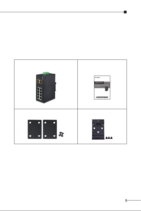
1. Package Contents
Thank you for purchasing PLANET industrial 10-port Gigabit
Ethernet Switch, IGS-1020TF. In the following section, the term
“Industrial Gigabit Ethernet Switch” means the IGS-1020TF.
Open the box of the Industrial Gigabit Ethernet Switch and
carefully unpack it. The box should contain the following items:
Industrial Gigabit Ethernet Switch x 1 User’s Manual x 1
Wall-mount Kit x DIN Rail Kit x 1
If any of these are missing or damaged, please contact your
dealer immediately; if possible, retain the carton including the
original packing material, and use them again to repack the
product in case there is a need to return it to us for repair.
3
Page 4

2. Hardware Introduction
Side View
2.1 Physical Dimensions
IGS-1020TF Industrial Gigabit Ethernet Switch dimensions (W
x D x H): 135 x 87.8 x 50mm
DIN-Rail Kit
Mounting Kit
Mounting Kit
Dimensions ( unit = mm )
Top View Rear View
109
864
1 2 3 4 5 6
V1+ V1- V2+V2-
PWR1
ACT
ACT
ACT
ACT
LNK
1000 LNK
10/100
LNK
LNK
100/1000X SFP
9 10
100
1000
Input
PWR2Fault
DC12~48V, AC 24V
P1 P2 FAULT
753
2
IGS-1020TF
1
Bottom View Front View
4
Page 5
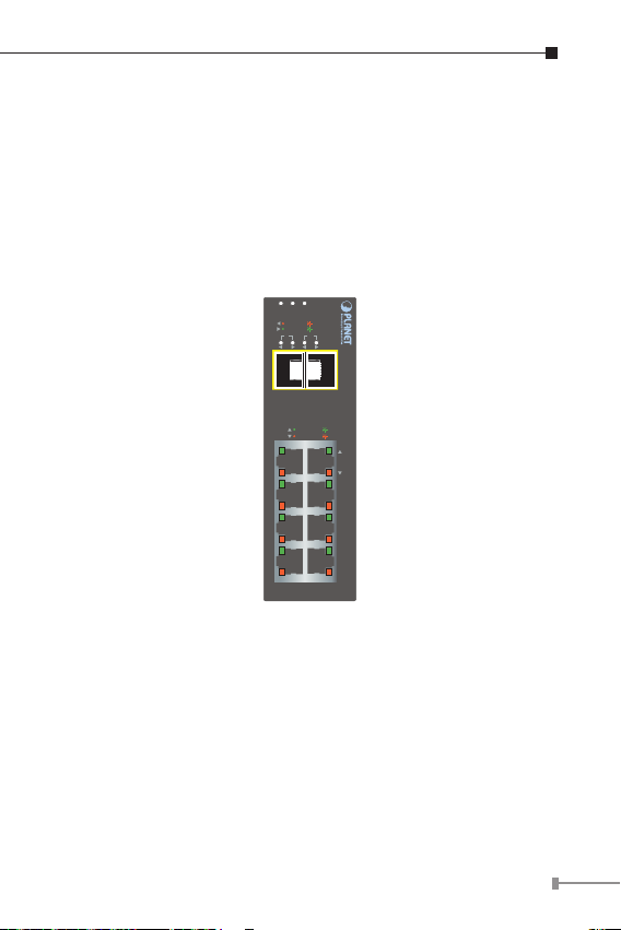
2.2 Switch Front Panel
The front panel of the Industrial Gigabit Ethernet Switch consists
of 8 auto-sensing 10/100/1000Mbps Ethernet RJ45 ports and
2 dual speed 100/1000BASE-X SFP slots. The LED Indicators
are also located on the RJ45 ports and SFP slots of the Gigabit
Ethernet Switch.
Figure 2-1 shows the front panel of Industrial Gigabit Ethernet
Switch.
P1 P2 FAULT
ACT
LNK
100
1000
LNK
ACT
9 10
109
100/1000X SFP
ACT
1000 LNK
LNK
10/100
ACT
7
5
3
1
Figure 2-1: IGS-1020TF Front Panel
Gigabit TP Interface
10/100/1000BASE-T Copper, RJ45 Twisted-pair: Up to 100
meters.
SFP Slot
100/1000BASE-X mini-GBIC slot, SFP (Small-form Factor
Pluggable) transceiver module: From 550 meters to 2km
(multi-mode ber) and 10/20/30/40/50/70/120 kilometers
(single-modeber).
8
6
4
2
IGS-1020TF
5
Page 6
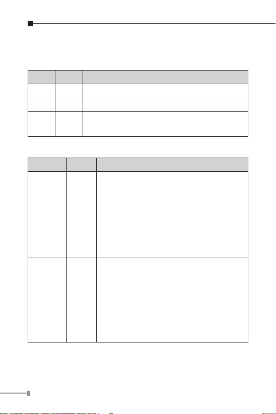
2.3 LED Indicators
System
LED Color Function
P1 Green Lit: indicates power 1 has power.
P2 Green Lit: indicates power 2 has power.
FAULT Red
Per 10/100/1000T Port
LED Color Function
100
LNK/ACT
1000
LNK/ACT
Lit: indicates either power 1 or power 2 has
no power.
Lit: indicates the link through that port is
successfully established at 100Mbps
or 10Mbps.
Orange
Green
Blinking: indicates that the Switch is
actively sending or receiving data
over that port.
Off: indicates the link through that port is
successfully established at 1000Mbps.
Lit: indicates the link through that port is
successfully established at 1000Mbps
or 10Mbps.
Blinking: indicates that the Switch is
actively sending or receiving data
over that port.
Off: indicates the link through that port is
successfully established at 100Mbps.
6
Page 7
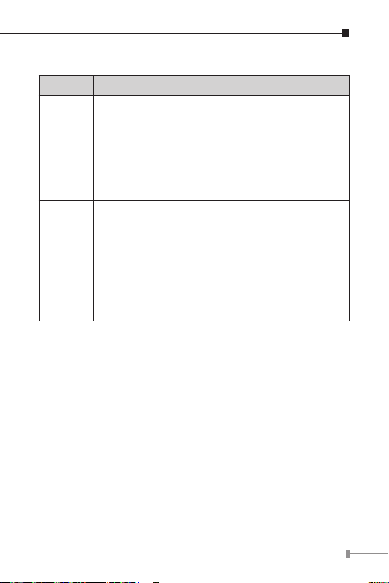
Per 100 / 1000X SFP Slot
LED Color Function
Lit: indicates the link through that port is
successfully established at 100Mbps.
100
LNK/ACT
1000
LNK/ACT
Orange
Green
Blinking: indicates that the Switch is
actively sending or receiving data
over that port.
Off: indicates the link through that port is
successfully established at 1000Mbps.
Lit: indicates the link through that port is
successfully established at 1000Mbps
or 10Mbps.
Blinking: indicates that the Switch is
actively sending or receiving data
over that port.
Off: indicates the link through that port is
successfully established at 100Mbps.
7
Page 8
2.4 Switch Upper Panel
The upper panel of the Industrial Gigabit Ethernet Switch
consists of one terminal block connector within two DC power
inputs,
Figure 2-2 shows the upper panel of the Industrial Gigabit
Ethernet Switch.
1 2 3 4 5 6
V1+ V1- V2+ V2-
PWR1
PWR2Fault
Input
DC12~48V, AC 24V
Figure 2-2: Industrial Gigabit Ethernet Switch Upper Panel
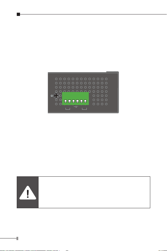
2.5 Wiring the Power Inputs
The 6-contact terminal block connector on the top panel of
Industrial Gigabit Ethernet Switch is used for two DC redundant
power inputs. Please follow the steps below to insert the power
wire.
When performing any of the procedures like
inserting the wires or tightening the wire-clamp
screws, make sure the power is OFF to prevent
from getting an electric shock.
8
Page 9
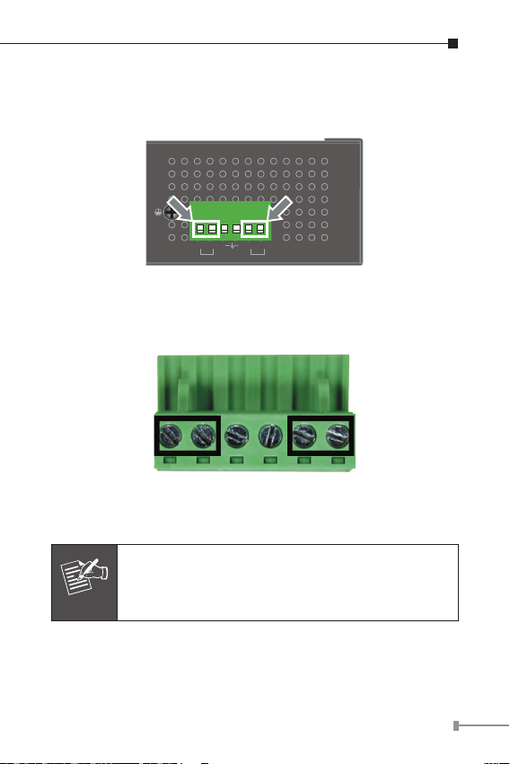
1. Insert positive and negative DC power wires into contacts 1
and 2 for POWER 1, or 5 and 6 for POWER 2.
1 2 3 4 5 6
V1+ V1- V2+ V2-
PWR1
PWR2Fault
Input
DC12~48V, AC 24V
2. Tighten the wire-clamp screws for preventing the wires from
loosening.
1 2 3 4 5 6
Power 1 Fault Power 2
+ - + -
1. The wire gauge for the terminal block should be
in the range between 12 and 24 AWG.
Note
2. The DC power input range is 12V ~ 48V DC.
9
Page 10

2.6 Wiring the Fault Alarm Contact
The fault alarm contacts are in the middle of the terminal block
connector as the picture shows below. Inserting the wires, the
Industrial Gigabit Ethernet Switch will detect the fault status of
the power failure and then forms an open circuit. The following
illustration shows an application example for wiring the fault
alarm contacts.
1 2 3 4 5 6
The Fault Alarm Contacts are
energized (CLOSE) for normal
Fault Alarm Contacts
Fault
operation and will OPEN when
failure occurs
Insert the wires into the fault alarm contacts
1. The wire gauge for the terminal block should be
in the range between 12 and 24 AWG.
Note
2. Alarm relay circuit accepts up to 30V, max. 3A
currents.
2.7 ProductSpecications
Model IGS-1020TF
HardwareSpecications
Copper Ports
8 x 10/100/1000BASE-T RJ45 TP
Auto-MDI/MDI-X, auto-negotiation
10
Page 11

SFP/mini-GBIC
Slots
Switch Processing
Scheme
Switch Fabric 20Gbps (non-blocking)
Switch Throughput
(packet per
second)
MAC Address Table 4K entries
Flow Control
Jumbo Frame 9216 bytes
Connector
Alarm
LED Indicator
2 1000BASE-SX/LX/BX SFP interfaces
(Port-9 and Port-10)
Compatible with 100BASE-FX SFP
Store-and-Forward
14.88Mpps@64bytes
Back pressure for half duplex
IEEE 802.3x pause frame for full duplex
Removable 6-pin terminal block
Pin 1/2 for Power 1; Pin 3/4 for fault
alarm; Pin 5/6 for Power 2
Provides one relay output for power
failure
Alarm Relay current carry ability: 1A @
DC 24V
3 x LED for System and Power:
Green: DC Power 1
Green: DC Power 2
Red: Power Fault
2 x LED for Per Copper Port (Port1~Port-8):
Green: 1000 LNK/ACT
Orange:100 LNK/ACT
2 x LED for Per mini-GBIC interface
(Port-9 and Port-10)
Green: 1000 LNK/ACT
Orange: 100 LNK/ACT
11
Page 12

ESD Protection 6KV DC
Enclosure IP30 type metal case
Installation DIN rail kit and wall mount ear
Dimensions
(W x D x H)
Weight 540g
Power
Requirements
Power
Consumption/
Dissipation
Twisted-pair
Cable
Fiber-Optic
Cable
56 x 87 x 135 mm
DC 12~48V or AC 24V
Redundant power with polarity reverses
protection function
8.7watts/29.69BTU
10BASE-T: 2-pair UTP Cat. 3, 4, 5, up to
100 meters
100BASE-TX: 2-pair UTP Cat. 5, 5e up to
100 meters
1000BASE-T: 4-pair UTP Cat. 5e, 6 up to
100 meters
1000BASE-SX :
50/125μmor 62.5/125μmmulti-mode
beroptic cable,up to550m
1000BASE-LX :
9/125μmsingle-mode beroptic cable,
up to 10/20/30/40/50/70/120 kilometers
(vary on SFP module)
100BASE-FX :
50/125μmor 62.5/125μmmulti-mode
beroptic cable,up to2 kilometers
9/125μmsingle-mode beroptic cable,
up to 20/40/60 kilometers (vary on SFP
module)
12
Page 13
Standards Conformance
IEEE 802.3 Ethernet/10BASE-T
IEEE 802.3u Fast Ethernet/100BASE-TX
IEEE 802.3ab Gigabit
Standards
Compliance
Regulatory
Compliance
Stability Testing
Environment
Temperature
Humidity
Ethernet/1000BASE-T
IEEE 802.3z Gigabit
Ethernet/1000BASE-SX/LX
IEEE 802.3x Full-Duplex Flow Control
IEEE802.3az EnergyEfcient Ethernet
(EEE)
IEEE 802.1p Cos
FCC Part 15 Class A, CE
IEC60068-2-32 (free fall)
IEC60068-2-27 (anti-shock)
IEC60068-2-6 (anti-vibration)
Operating: -40~75 degrees C
Storage: -40~75 degrees C
Operating: 5~95% (non-condensing)
Storage: 5~95% (non-condensing)
13
Page 14

3. Installation
This section describes the functionalities of the Industrial
Gigabit Ethernet Switch’s components and guides how to install
it on the DIN-rail and wall. Basic knowledge of networking is
assumed. Please read this chapter completely before continuing.
This following picture is telling the user how
to install the device, and the device is not IGS-
Note
3.1 DIN-rail Mounting Installation
The DIN-rail is screwed on the Industrial Gigabit Ethernet Switch
when out of factory. When replacing the wall-mount application
with DIN-rail application, Industrial Gigabit Ethernet Switch
is needed. Please refer to the following gures to screw the
DIN-rail on the Industrial Gigabit Ethernet Switch. To hang the
Industrial Gigabit Ethernet Switch, follow the following steps:
Step 1: Screw the DIN-rail on the Industrial Gigabit Ethernet
1020TF.
Switch.
14
Page 15

Step 2: Lightly insert the bottom of the switch into the track
1
2
Step 3: Make sure if the DIN-Rail is tightly secured on the
track.
Step 4: Please refer to the following procedures to remove the
Industrial Gigabit Ethernet Switch from the track.
1
2
15
Page 16

Step 5: Lightly pull out the bottom of the switch for removing
it from the track.
3.2 Wall-mount Plate Mounting
To install the Industrial Gigabit Ethernet Switch on the wall,
please follow the instructions described below.
Step 1: To remove the DIN-Rail from the Industrial Gigabit
Ethernet Switch, loosen the screws to remove the
DIN-rail.
Step 2: Place the wallmount plate on the rear panel of the
Industrial Gigabit Ethernet Switch.
Step 3: Use the screws to screw the wallmount plate on the
Industrial Gigabit Ethernet Switch.
Step 4: Use the hook holes at the corners of the wallmount
plate to hang the Industrial Gigabit Ethernet Switch on
the wall.
Step 5: To remove the wallmount plate, reverse the steps
above.
16
Page 17

3.3 Installing the SFP Transceiver
The sections describe how to insert an SFP transceiver into an
SFP slot.
The SFP transceivers are hot-pluggable and hot-swappable.
You can plug in and out the transceiver to/from any SFP port
without having to power down the Industrial Gigabit Ethernet
Switch as Figure 2-3 shows.
MGB/MFB
Series Module
Figure 3-1: Plug-in the SFP Transceiver
PLANET Industrial Gigabit Ethernet Switch supports 100/1000
dual mode with both single mode and multi-mode SFP
transceivers.
1. Before we connect Industrial Gigabit Ethernet Switch to the
other network device, we have to make sure both sides of
the SFP transceivers are with the same media type, for
example, 1000BASE-SX to 1000BASE-SX, 1000BASE-LX to
1000BASE-LX.
17
Page 18

2.Check whether the ber-optic cable type matches with the
SFP transceiver requirement.
To connect to 1000BASE-SX SFP transceiver, please use
the multi-mode ber cable with one side being the male
duplex LC connector type.
To connect to 1000BASE-LX or 1000BASE-BX SFP trans-
ceiver, please use the single-mode ber cable with one
side being the male duplex LC connector type.
Connect the Fiber Cable
1. Insert the duplex LC connector into the SFP transceiver.
2. Connect the other end of the cable to a device with SFP
transceiver installed.
3. Check the LNK/ACT LED of the SFP slot on the front of the
Industrial Gigabit Ethernet Switch. Ensure that the SFP transceiver is operating correctly.
4. Check the Link mode of the SFP port if the link fails.
It is recommended to use PLANET SFPs on the
Industrial Gigabit Ethernet Switch. If you insert an
Note
SFP transceiver that is not supported, the Industrial Gigabit Ethernet Switch will not recognize it.
18
Page 19

3.4 Removing the Transceiver Module
1. Make sure there is no network activity by consulting or
checking with the network administrator. Or through the
management interface of the switch/converter (if available) to
disable the port in advance.
2. Remove the Fiber Optic Cable gently.
3. Turn the lever of the MGB/MFB module to a horizontal position.
4. Pull out the module gently through the lever.
MGB/MFB
Series Module
12
Figure 3-2: Pull Out from the Transceiver
Never pull out the module without pulling the
lever or the push bolts on the module. Directly
pulling out the module with force could damage
Note
the module and the SFP module slot of the
Industrial Gigabit Ethernet Switch.
19
Page 20

4. Troubleshooting
This chapter contains information to help you solve issues.
If the Industrial Gigabit Ethernet Switch is not functioning
properly, make sure the Industrial Gigabit Ethernet Switch was
set up according to instructions in this manual.
The per port LED is not lit
Solution:
Check the cable connection of the Industrial Gigabit Ethernet
Switch.
Per port LED is lit, but the trafc is irregular
Solution:
Check whether the attached device is not set to dedicated full
duplex. Some devices use a physical or software switch to
change duplex modes. Auto-negotiation may not recognize this
type of full-duplex setting.
Why the Industrial Gigabit Ethernet Switch doesn’t
connect to the network
Solution:
Check each port LED on the Industrial Gigabit Ethernet Switch.
Try another port on the Industrial Gigabit Ethernet Switch. Make
sure the cable is installed properly and the right type. Turn off
the power. After a while, turn on the power again.
Can I install MGB-SX or other non wide temperature
SFP module into SFP slot of Industrial Gigabit Ethernet
Switch?
Solution:
Yes, you can. However, the MGB-SX and the other non wide
temperature SFP module cannot operate under -40 to 75
degrees C.
20
Page 21

APPENDIX A: Networking Connection
A.1 Switch’s RJ45 Pin Assignments
1000Mbps, 1000BASE-T
Contact MDI MDI-X
1 BI_DA+ BI_DB+
2 BI_DA- BI_DB-
3 BI_DB+ BI_DA+
4 BI_DC+ BI_DD+
5 BI_DC- BI_DD-
6 BI_DB- BI_DA-
7 BI_DD+ BI_DC+
8 BI_DD- BI_DC-
10/100Mbps, 10/100BASE-TX
RJ45 Connector pin assignment
MDI
Contact
1 Tx + (transmit) Rx + (receive)
2 Tx - (transmit) Rx - (receive)
3 Rx + (receive) Tx + (transmit)
4, 5 Not used
6 Rx - (receive) Tx - (transmit)
7, 8 Not used
Media Dependent
Interface
MDI-X
Media Dependent
Interface -Cross
21
Page 22

A.2 RJ45 Cable Pin Assignments
The standard RJ45 receptacle/connector
There are 8 wires on a standard UTP/STP cable and each wire is
color-coded. The following shows the pin allocation and color of
straight-through cable and crossover cable connection:
Straight Cable
12345678
12345678
Cross Over Cable
12345678
12345678
SIDE 1
SIDE 2
SIDE 1
SIDE 2
SIDE 1
1 = White/Orange
2 = Orange
3 = White/Green
4 = Blue
5 = White/Blue
6 = Green
7 = White/Brown
8 = Brown
SIDE 1 SIDE 2
1 = White/Orange
2 = Orange
3 = White/Green
4 = Blue
5 = White/Blue
6 = Green
7 = White/Brown
8 = Brown
SIDE 2
1 = White/Orange
2 = Orange
3 = White/Green
4 = Blue
5 = White/Blue
6 = Green
7 = White/Brown
8 = Brown
1 = White/Green
2 = Green
3 = White/Orange
4 = Blue
5 = White/Blue
6 = Orange
7 = White/Brown
8 = Brown
Figure A-1: Straight-through and Crossover Cable
Please make sure your connected cables are with the same pin
assignment and color as the above picture before deploying the
cables into your network.
22
Page 23

A.3 Fiber Optic Cable Connection Parameter
The wiring details are shown below:
100FX Fiber Optic Cables:
Standard Fiber Type CableSpecications
100BASE-FX
(1300nm)
100BASE-FX
(1310nm)
100BASE-BX-U
(TX:1310/RX:1550)
100BASE-BX-D
(TX:1550/RX:1310)
Multi-mode
Multi-mode
Single-mode 9/125μm
Single-mode 9/125μm
1000X Fiber Optic Cables:
Standard Fiber Type CableSpecications
1000BASE-SX
(850nm)
1000BASE-LX
(1300nm)
Multi-mode 50/125μmor62.5/125μm
Multi-mode 50/125μmor62.5/125μm
Single-mode 9/125μm
50/125μmor
62.5/125μm
50/125μmor
62.5/125μm
23
Page 24

Wiring Distances:
Standard Fiber
1000BASE- SX MM
1000BASE- LX
MM
SM 9 N/A 5000*
Diameter
(micron)
62.5
62.5
50
50
62.5
50
50
Modal
Bandwidth
(MHz * km)
100
200
400
500
5
4
5
Max. Distance
(meters)
220
275
500
550
550
24
Page 25

APPENDIX B: Approved PLANET SFP
Transceivers
The following list of approved PLANET SFP transceivers is correct
at the time of publication:
Gigabit SFP Transceiver Modules
MGB-GT SFP-Port 1000BASE-T Module - 100m
MGB-SX SFP-Port 1000BASE-SX mini-GBIC module - 550m
MGB-SX2 SFP-Port 1000BASE-SX mini-GBIC module – 2km
MGB-LX SFP-Port 1000BASE-LX mini-GBIC module - 10km
MGB-L30 SFP-Port 1000BASE-LX mini-GBIC module - 30km
MGB-L50 SFP-Port 1000BASE-LX mini-GBIC module - 50km
MGB-L70 SFP-Port 1000BASE-LX mini-GBIC module - 70km
MGB-L120 SFP-Port 1000BASE-LX mini-GBIC module - 120km
MGB-LA10
MGB-LB10
MGB-LA20
MGB-LB20
MGB-LA40
MGB-LB40
SFP-Port 1000BASE-LX (WDM, TX:1310nm) miniGBIC module - 10km
SFP-Port 1000BASE-LX (WDM, TX:1550nm) miniGBIC module - 10km
SFP-Port 1000BASE-LX (WDM, TX:1310nm) miniGBIC module – 20km
SFP-Port 1000BASE-LX (WDM, TX:1550nm) miniGBIC module - 20km
SFP-Port 1000BASE-LX (WDM, TX:1310nm) miniGBIC module - 40km
SFP-Port 1000BASE-LX (WDM, TX:1550nm) miniGBIC module - 40km
25
Page 26

MGB-LA60
MGB-LB60
MGB-TSX
MGB-TLX
MGB-TL30
MGB-TL70
MGB-TLA10
MGB-TLB10
MGB-TLA20
MGB-TLB20
MGB-TLA40
MGB-TLB40
MGB-TLA60
MGB-TLB60
SFP-Port 1000BASE-LX (WDM, TX:1310nm) miniGBIC module - 60km
SFP-Port 1000BASE-LX (WDM, TX:1550nm) miniGBIC module - 60km
SFP-Port 1000BASE-SX mini-GBIC module - 550m
(-40~75°C)
SFP-Port 1000BASE-LX mini-GBIC module - 10km
(-40~75°C)
SFP-Port 1000BASE-LX mini-GBIC module - 30km
(-40~75°C)
SFP-Port 1000BASE-LX mini-GBIC module - 70km
(-40~75°C)
SFP-Port 1000BASE-LX (WDM, TX:1310nm) miniGBIC module - 10km (-40~75°C)
SFP-Port 1000BASE-LX (WDM, TX:1550nm) miniGBIC module - 10km (-40~75°C)
SFP-Port 1000BASE-LX (WDM, TX:1310nm) miniGBIC module – 20km (-40~75°C)
SFP-Port 1000BASE-LX (WDM, TX:1550nm) miniGBIC module - 20km (-40~75°C)
SFP-Port 1000BASE-LX (WDM, TX:1310nm) miniGBIC module - 40km (-40~75°C)
SFP-Port 1000BASE-LX (WDM, TX:1550nm) miniGBIC module - 40km (-40~75°C)
SFP-Port 1000BASE-LX (WDM, TX:1310nm) miniGBIC module - 60km (-40~75°C)
SFP-Port 1000BASE-LX (WDM, TX:1550nm) miniGBIC module - 60km (-40~75°C)
26
Page 27

Fast Ethernet SFP Transceiver Modules
MFB-FX SFP-Port 100BASE-FX Transceiver (1310nm) - 2km
MFB-F20
MFB-F40
MFB-F60
MFB-F120
MFB-FA20
MFB-FB20
MFB-TFX
MFB-TF20
MFB-TFA20
MFB-TFB20
MFB-TFA40
MFB-TFB40
SFP-Port 100BASE-FX Transceiver (1310nm) 20km
SFP-Port 100BASE-FX Transceiver (1310nm) 40km
SFP-Port 100BASE-FX Transceiver (1310nm) 60km
SFP-Port 100BASE-FX Transceiver (1550nm) 120km
SFP-Port 100BASE-BX Transceiver (WDM,
TX:1310nm) - 20km
SFP-Port 100BASE-BX Transceiver (WDM,
TX:1550nm) - 20km
SFP-Port 100BASE-FX Transceiver (1310nm) - 2km
(-40~75°C)
SFP-Port 100BASE-FX Transceiver (1310nm) 20km (-40~75°C)
SFP-Port 100BASE-BX Transceiver (WDM,
TX:1310nm) - 20km (-40~75°C)
SFP-Port 100BASE-BX Transceiver (WDM,
TX:1550nm) - 20km (-40~75°C)
SFP-Port 100BASE-BX Transceiver (WDM,
TX:1310nm) - 40km (-40~75°C)
SFP-Port 100BASE-BX Transceiver (WDM,
TX:1550nm) - 40km (-40~75°C)
27
Page 28

 Loading...