

Page 1
User’s Manual
Page 2

User’s Manual
2
Trademarks
Copyright © PLANET Technology Corp. 2016.
Contents are subject to revision without prior notice.
PLANET is a registered trademark of PLANET Technology Corp. All other trademarks belong to their respective owners.
Disclaimer
PLANET Technology does not warrant that the hardware will work properly in all environments and applications, and makes no
warranty and representation, either implied or expressed, with respect to the quality, performance, merchantability, or fitness for
a particular purpose. PLANET has made every effort to ensure that this User's Manual is accurate; PLANET disclaims liability
for any inaccuracies or omissions that may have occurred.
Information in this User's Manual is subject to change without notice and does not represent a commitment on the part of
PLANET. PLANET assumes no responsibility for any inaccuracies that may be contained in this User's Manual. PLANET makes
no commitment to update or keep current the information in this User's Manual, and reserves the right to make improvements to
this User's Manual and/or to the products described in this User's Manual, at any time without notice.
If you find information in this manual that is incorrect, misleading, or incomplete, we would appreciate your comments and
suggestions.
FCC Warning
This equipment has been tested and found to comply with the limits for a Class A digital device, pursuant to Part 15 of the FCC
Rules. These limits are designed to provide reasonable protection against harmful interference when the equipment is operated
in a commercial environment. This equipment generates, uses, and can radiate radio frequency energy and, if not installed and
used in accordance with the Instruction manual, may cause harmful interference to radio communications. Operation of this
equipment in a residential area is likely to cause harmful interference in which case the user will be required to correct the
interference at his own expense.
CE Mark Warning
This is a Class A product. In a domestic environment, this product may cause radio interference, in which case the user may be
required to take adequate measures.
Energy Saving Note of the Device
This power required device does not support Standby mode operation. For energy saving, please remove the power cable to
disconnect the device from the power circuit. In view of saving the energy and reducing the unnecessary power consumption, it
is strongly suggested to remove the power connection for the device if this device is not intended to be active.
WEEE Warning
To avoid the potential effects on the environment and human health as a result of the presence of
hazardous substances in electrical and electronic equipment, end users of electrical and electronic
equipment should understand the meaning of the crossed-out wheeled bin symbol. Do not dispose of
WEEE as unsorted municipal waste and have to collect such WEEE separately.
Revision
User's Manual of PLANET Industrial L2+ Multi-port Full Gigabit Industrial Managed Switch
FOR MODEL: IGS-10020MT/10020PT/10020HPT/10080MFT/12040MT/20040MT/20160HPT
REVISION: 1.4 (Aug., 2016)
Part No: EM-IGS-Series_v1.4
Page 3

User’s Manual
3
TABLE OF CONTENTS
1. INTRODUCTION .................................................................................................................. 10
1.1 Packet Contents ......................................................................................................................................... 10
1.2 Product Description ................................................................................................................................... 11
1.3 How to Use This Manual ............................................................................................................................ 15
1.4 Product Features ........................................................................................................................................ 16
1.5 Product Specificatio n s .............................................................................................................................. 19
2. INSTALLATION ................................................................................................................... 30
2.1 Hardware Description ................................................................................................................................ 30
2.1.1 Physical Dimensions ........................................................................................................................................... 30
2.1.2 Front Panel .......................................................................................................................................................... 37
2.1.3 LED Indications ................................................................................................................................................... 41
2.1.4 Switch Upper Panel ............................................................................................................................................. 45
2.1.5 Wiring the Fault Alarm Contact ........................................................................................................................... 49
2.1.6 Wiring the Digital Input/Output ............................................................................................................................. 49
2.2 Installing the Industrial Managed Switch ................................................................................................. 51
2.2.1 Installation Steps.................................................................................................................................................. 51
2.2.2 DIN-rail Mounting ................................................................................................................................................. 53
2.2.3 Wall Mount Plate Mounting .................................................................................................................................. 55
2.3 Cabling ........................................................................................................................................................ 56
2.3.1 Installing the SFP Transceiver ............................................................................................................................. 57
2.3.2 Removing the SFP Transceiver ........................................................................................................................... 60
3. SWITCH MANAGEMENT .................................................................................................... 61
3.1 Requirements .............................................................................................................................................. 61
3.2 Management Access Overview ................................................................................................................. 62
3.3 CLI Mode Management .............................................................................................................................. 63
3.4 Web Management ....................................................................................................................................... 65
3.5 SNMP-based Network Management ......................................................................................................... 66
3.6 PLANET Smart Discovery Utility .............................................................................................................. 67
4. WEB CONFIGURATION ...................................................................................................... 69
Page 4

User’s Manual
4
4.1 Main Web page ........................................................................................................................................... 72
4.2 System ......................................................................................................................................................... 74
4.2.1 System Information .............................................................................................................................................. 75
4.2.2 IP Configuration ................................................................................................................................................... 76
4.2.3 IP Status .............................................................................................................................................................. 78
4.2.4 Users Configuration ............................................................................................................................................. 79
4.2.5 Privilege Levels ................................................................................................................................................... 82
4.2.6 NTP Configuration ............................................................................................................................................... 84
4.2.7 Time Configuration .............................................................................................................................................. 85
4.2.8 UPnP ................................................................................................................................................................... 86
4.2.9 DHCP Relay ........................................................................................................................................................ 87
4.2.10 DHCP Relay Statistics ....................................................................................................................................... 89
4.2.11 CPU Load .......................................................................................................................................................... 91
4.2.12 System Log ........................................................................................................................................................ 92
4.2.13 Detailed Log ...................................................................................................................................................... 93
4.2.14 Remote Syslog .................................................................................................................................................. 94
4.2.15 SMTP Configuration .......................................................................................................................................... 95
4.2.16 Digital Input/Output ............................................................................................................................................ 96
4.2.17 Fault Alarm ........................................................................................................................................................ 98
4.2.18 Web Firmware Upgrade ..................................................................................................................................... 99
4.2.19 TFTP Firmware Upgrade ................................................................................................................................. 100
4.2.20 Save Startup Config ......................................................................................................................................... 101
4.2.21 Configuration Download .................................................................................................................................. 101
4.2.22 Configuration Upload ....................................................................................................................................... 102
4.2.23 Configuration Activate ...................................................................................................................................... 102
4.2.24 Configuration Delete ........................................................................................................................................ 103
4.2.25 Image Select .................................................................................................................................................... 103
4.2.26 Factory Default ................................................................................................................................................ 104
4.2.27 System Reboot ................................................................................................................................................ 105
4.3 Simple Network Management Protocol .................................................................................................. 106
4.3.1 SNMP Overview ................................................................................................................................................ 106
4.3.2 SNMP System Configuration ............................................................................................................................. 107
4.3.3 SNMP Trap Configuration .................................................................................................................................. 109
4.3.4 SNMP System Information ................................................................................................................................ 111
4.3.5 SNMPv3 Configuration ...................................................................................................................................... 11 2
4.3.5.1 SNMPv3 Communities ............................................................................................................................ 11 2
4.3.5.2 SNMPv3 Users ........................................................................................................................................ 11 3
4.3.5.3 SNMPv3 Groups ...................................................................................................................................... 11 4
4.3.5.4 SNMPv3 Views ........................................................................................................................................ 11 5
Page 5

User’s Manual
5
4.3.5.5 SNMPv3 Access ...................................................................................................................................... 116
4.4 Port Management ..................................................................................................................................... 118
4.4.1 Port Configuration .............................................................................................................................................. 118
4.4.2 Port Statistics Overview ..................................................................................................................................... 120
4.4.3 Port Statistics Detail ........................................................................................................................................... 121
4.4.4 SFP Module Information .................................................................................................................................... 123
4.4.5 Port Mirror .......................................................................................................................................................... 124
4.5 Link Aggregation ...................................................................................................................................... 127
4.5.1 Static Aggregation .............................................................................................................................................. 129
4.5.2 LACP Configuration ........................................................................................................................................... 130
4.5.3 LACP System Status ......................................................................................................................................... 132
4.5.4 LACP Port Status ............................................................................................................................................... 133
4.5.5 LACP Port Statistics ........................................................................................................................................... 134
4.6 VLAN .......................................................................................................................................................... 135
4.6.1 VLAN Overview ................................................................................................................................................. 135
4.6.2 IEEE 802.1Q VLAN ........................................................................................................................................... 136
4.6.3 VLAN Port Configuration ................................................................................................................................... 139
4.6.4 VLAN Membership Status .................................................................................................................................. 145
4.6.5 VLAN Port Status ............................................................................................................................................... 146
4.6.6 Private VLAN ..................................................................................................................................................... 147
4.6.7 Port Isolation ...................................................................................................................................................... 149
4.6.8 VLAN setting example: ...................................................................................................................................... 151
4.6.8.1 Two Separate 802.1Q VLANs .................................................................................................................. 151
4.6.8.2 VLAN Trunking between two 802.1Q aware switches ............................................................................. 154
4.6.8.3 Port Isolate .............................................................................................................................................. 156
4.6.9 MAC-based VLAN ............................................................................................................................................. 157
4.6.10 Protocol-based VLAN ...................................................................................................................................... 159
4.6.11 Protocol-based VLAN Membership .................................................................................................................. 161
4.7 Spanning Tree Protocol ........................................................................................................................... 162
4.7.1 Theory ............................................................................................................................................................... 162
4.7.2 STP System Configuration ................................................................................................................................ 168
4.7.3 Bridge Status ..................................................................................................................................................... 170
4.7.4 CIST Port Configuration ..................................................................................................................................... 171
4.7.5 MSTI Priorities ................................................................................................................................................... 174
4.7.6 MSTI Configuration ............................................................................................................................................ 175
4.7.7 MSTI Ports Configuration .................................................................................................................................. 176
4.7.8 Port Status ......................................................................................................................................................... 178
4.7.9 Port Statistics ..................................................................................................................................................... 179
Page 6

User’s Manual
6
4.8 Multicast .................................................................................................................................................... 180
4.8.1 IGMP Snooping ................................................................................................................................................. 180
4.8.2 Profile Table ....................................................................................................................................................... 184
4.8.3 Address Entry .................................................................................................................................................... 185
4.8.4 IGMP Snooping Configuration ........................................................................................................................... 186
4.8.5 IGMP Snooping VLAN Configuration ................................................................................................................. 188
4.8.6 IGMP Snooping Port Group Filtering ................................................................................................................. 190
4.8.7 IGMP Snooping Status ...................................................................................................................................... 191
4.8.8 IGMP Group Information .................................................................................................................................... 192
4.8.9 IGMPv3 Information ........................................................................................................................................... 193
4.8.10 MLD Snooping Configuration ........................................................................................................................... 194
4.8.11 MLD Snooping VLAN Configuration................................................................................................................. 195
4.8.12 MLD Snooping Port Group Filtering ................................................................................................................. 197
4.8.13 MLD Snooping Status ...................................................................................................................................... 198
4.8.14 MLD Group Information ................................................................................................................................... 199
4.8.15 MLDv2 Information .......................................................................................................................................... 200
4.8.16 MVR (Multicast VLAN Registration) ................................................................................................................. 201
4.8.17 MVR Status ...................................................................................................................................................... 204
4.8.18 MVR Groups Information ................................................................................................................................. 205
4.8.19 MVR SFM Information ..................................................................................................................................... 206
4.9 Quality of Service ..................................................................................................................................... 207
4.9.1 Understanding QoS ........................................................................................................................................... 207
4.9.2 Port Policing ...................................................................................................................................................... 208
4.9.3 Port Classification .............................................................................................................................................. 209
4.9.4 Port Scheduler ................................................................................................................................................... 2 11
4.9.5 Port Shaping ...................................................................................................................................................... 212
4.9.5.1 QoS Egress Port Schedule and Shapers ................................................................................................ 213
4.9.6 Port Tag Remarking ........................................................................................................................................... 215
4.9.6.1 QoS Egress Port Tag Remarking ............................................................................................................. 216
4.9.7 Port DSCP ......................................................................................................................................................... 217
4.9.8 DSCP-based QoS ............................................................................................................................................. 219
4.9.9 DSCP Translation .............................................................................................................................................. 220
4.9.10 DSCP Classification ......................................................................................................................................... 221
4.9.11 QoS Control List............................................................................................................................................... 222
4.9.11.1 QoS Control Entry Configuration ........................................................................................................... 224
4.9.12 QCL Status ...................................................................................................................................................... 226
4.9.13 Storm Control Configuration ............................................................................................................................ 228
4.9.14 QoS Statistics .................................................................................................................................................. 229
4.9.15 Voice VLAN Configuration ............................................................................................................................... 230
4.9.16 Voice VLAN OUI Table ..................................................................................................................................... 232
Page 7

User’s Manual
7
4.10 Access Control List ................................................................................................................................ 233
4.10.1 Access Control List Status ............................................................................................................................... 233
4.10.2 Access Control List Configuration .................................................................................................................... 235
4.10.3 ACE Configuration ........................................................................................................................................... 237
4.10.4 ACL Ports Configuration .................................................................................................................................. 247
4.10.5 ACL Rate Limiter Configuration ....................................................................................................................... 249
4.11 Authentication ......................................................................................................................................... 250
4.11.1 Understanding IEEE 802.1X Port-based Authentication .................................................................................. 251
4.11.2 Authentication Configuration ............................................................................................................................ 255
4.11.3 Network Access Server Configuration .............................................................................................................. 256
4.11.4 Network Access Overview ............................................................................................................................... 267
4.11.5 Network Access Statistics ................................................................................................................................ 268
4.11.6 RADIUS ........................................................................................................................................................... 275
4.11.7 TACACS+ ........................................................................................................................................................ 277
4.11.8 RADIUS Overview ........................................................................................................................................... 278
4.11.9 RADIUS Details ............................................................................................................................................... 280
4.11.10 Windows Platform RADIUS Server Configuration .......................................................................................... 286
4.11.11 802.1X Client Configuration ........................................................................................................................... 291
4.12 Security ................................................................................................................................................... 294
4.12.1 Port Limit Control ............................................................................................................................................. 294
4.12.2 Access Management ....................................................................................................................................... 297
4.12.3 Access Management Statistics ........................................................................................................................ 298
4.12.4 HTTPs ............................................................................................................................................................. 299
4.12.5 SSH ................................................................................................................................................................. 300
4.12.6 Port Security Status ......................................................................................................................................... 301
4.12.7 Port Security Detail .......................................................................................................................................... 303
4.12.8 DHCP Snooping .............................................................................................................................................. 304
4.12.9 Snooping Table ................................................................................................................................................ 306
4.12.10 IP Source Guard Configuration ...................................................................................................................... 306
4.12.11 IP Source Guard Static Table ......................................................................................................................... 308
4.12.12 Dynamic IP Source Guard Table .................................................................................................................... 309
4.12.13 ARP Inspection .............................................................................................................................................. 310
4.12.14 ARP Inspection Static Table ........................................................................................................................... 311
4.12.15 Dynamic ARP Inspection Table ...................................................................................................................... 312
4.13 MAC Address Table ................................................................................................................................ 314
4.13.1 MAC Table Configuration ................................................................................................................................. 314
4.13.2 MAC Address Table Status .............................................................................................................................. 316
4.14 LLDP ........................................................................................................................................................ 318
Page 8

User’s Manual
8
4.14.1 Link Layer Discovery Protocol ......................................................................................................................... 318
4.14.2 LLDP Configuration ......................................................................................................................................... 318
4.14.3 LLDP MED Configuration ................................................................................................................................ 321
4.14.4 LLDP-MED Neighbor ....................................................................................................................................... 328
4.14.5 Neighbor .......................................................................................................................................................... 332
4.14.6 Port Statistics ................................................................................................................................................... 333
4.15 Network Diagnostics .............................................................................................................................. 335
4.15.1 Ping ................................................................................................................................................................. 336
4.15.2 IPv6 Ping ......................................................................................................................................................... 337
4.15.3 Remote IP Ping Test ........................................................................................................................................ 338
4.15.4 Cable Diagnostics ............................................................................................................................................ 339
4.16 Power over Ethernet (IGS-10020PT/10020HPT/20160HPT) ................................................................ 341
4.16.1 Power over Ethernet Powered Device ............................................................................................................. 341
4.16.2 System Configuration ...................................................................................................................................... 342
4.16.3 Power Over Ethernet Configuration ................................................................................................................. 343
4.16.4 Port Sequential ................................................................................................................................................ 345
4.16.5 Port Configuration ............................................................................................................................................ 346
4.16.6 PoE Status ....................................................................................................................................................... 348
4.16.7 PoE Schedule .................................................................................................................................................. 350
4.16.8 LLDP PoE Neighbours ..................................................................................................................................... 352
4.17 Loop Protection ...................................................................................................................................... 354
4.17.1 Configuration ................................................................................................................................................... 354
4.17.2 Loop Protection Status..................................................................................................................................... 355
4.18 RMON ....................................................................................................................................................... 357
4.18.1 RMON Alarm Configuration ............................................................................................................................. 357
4.18.2 RMON Alarm Status......................................................................................................................................... 359
4.18.3 RMON Event Configuration ............................................................................................................................. 360
4.18.4 RMON Event Status......................................................................................................................................... 361
4.18.5 RMON History Configuration ........................................................................................................................... 362
4.18.6 RMON History Status....................................................................................................................................... 363
4.18.7 RMON Statistics Configuration ........................................................................................................................ 364
4.18.8 RMON Statistics Status .................................................................................................................................... 365
4.19 PTP (IGS-12040MT/20040MT/20160HPT Only) ..................................................................................... 367
4.19.1 PTP Configuration ........................................................................................................................................... 367
4.19.2 PTP Status ....................................................................................................................................................... 371
4.20 Ring .......................................................................................................................................................... 373
4.20.1 MEP Configuration........................................................................................................................................... 374
Page 9

User’s Manual
9
4.20.2 Detailed MEP Configuration ............................................................................................................................ 375
4.20.3 Ethernet Ring Protocol Switch ......................................................................................................................... 378
4.20.4 Ethernet Ring Protocol Switch Configuration ................................................................................................... 380
4.20.5 Ring Wizard ..................................................................................................................................................... 383
4.20.6 Ring Wizard Example: ..................................................................................................................................... 384
5. SWITCH OPERATION ....................................................................................................... 387
5.1 Address Table ........................................................................................................................................... 387
5.2 Learning .................................................................................................................................................... 387
5.3 Forwarding & Filtering ............................................................................................................................. 387
5.4 Store-and-Forward ................................................................................................................................... 387
5.5 Auto-Negotiation ...................................................................................................................................... 388
6. TROUBLESHOOTING ....................................................................................................... 389
APPENDIX A : Networking Connection ............................................................................... 390
A.1 Switch's Data RJ45 Pin Assignments - 1000Mbps, 1000BASE-T ........................................................ 390
A.2 10/100Mbps, 10/100BASE-TX .................................................................................................................. 390
APPENDIX B : GLOSSARY .................................................................................................. 392
Page 10
User’s Manual
10
Model Name
Item
The Industrial
Managed Switch
RS232 to RJ45
Console Cable
1. INTRODUCTION
The descriptions of PLANET L2+ Industrial Managed Switch series, such as IGS-10020, IGS-10080MFT, IGS-12040MT,
IGS-20040MT and IGS-20160HPT, are as follows:
IGS-10020MT Industrial 8-Port 10/100/1000T + 2-Port 100/1000X SFP Managed Switch
IGS-10020PT Industrial 8-Port 10/100/1000T 802.3af PoE + 2-Port 100/1000X SFP Managed Switch
IGS-10020HPT Industrial 8-Port 10/100/1000T 802.3af/at PoE + 2-Port 100/1000X SFP Managed Switch
IGS-10080MFT Industrial 8-Port 100/1000X SFP + 2-Port 10/100/1000T Managed Switch
IGS-12040MT Industrial 8-Port 10/100/1000T + 4-Port 100/1000X SFP Managed Switch
IGS-20040MT Industrial 16-Port 10/100/1000T + 4-Port 100/1000X SFP Managed Switch
IGS-20160HPT
“Industrial Managed Switch” is used as an alternative name for the above models in this user’s manual.
Industrial 16-Port 10/100/1000T 802.3at PoE + 2-Port 10/100/100T + 2-Port 100/1000X SFP Managed
Switch
1.1 Packet Contents
Open the box of the Industrial Managed Switch and carefully unpack it. The box should contain the following items:
Quick Installation
Guide
DIN Rail Kit
IGS-10020MT
■ ■ ■ ■ ■ ■
■ ■ ■ ■ ■ ■
x
■ ■ ■ ■ ■ ■
IGS-10020PT
IGS-10020HPT
■ ■ ■ ■ ■
IGS-10080MFT IGS-12040MT IGS-20040MT IGS-20160HPT
Wall Mounting Kit
SFP Dust Caps
RJ45 Dust Caps
If any of these are missing or damaged, please contact your dealer immediately; if possible, retain the carton including the
original packing material, and use them again to repack the product in case there is a need to return it to us for repair.
■ ■ ■ ■ ■ ■
2 2 8 4 4 2
8 9 3 9 17 19
Page 11

User’s Manual
11
1.2 Product Description
PLANET Industrial Managed Switch is specially designed to build a full Gigabit backbone to transmit reliable and high-speed
data in heavy industrial demanding environments and forward data to remote network through fiber optic cabling. It comes with
an IP30 rugged case and redundant power system. Besides support for 40Gbps switch fabric to handle extremely large
amounts of video, voice and important data in a secure topology, the Industrial Managed Switch provides user-friendly but
advanced IPv6/ IPv4 management interfaces and abundant L2/L4 switching functions. It is the best investment for expanding
industrial business or upgrading its network infrastructure.
Redundant Ring, Fast Recovery for Critical Network Applications
The Industrial Managed Switch supports redundant ring technology and features strong, rapid self-recovery capability to prevent
interruptions and external intrusions. It incorporates advanced ITU-T G.8032 ERPS (Ethernet Ring Protection Switching)
technology, Spanning Tree Protocol (802.1s MSTP), and redundant power input system into customer’s industrial automation
network to enhance system reliability and uptime in harsh factory environments. In a certain simple Ring network, the recovery
time of data link can be as fast as 20ms.
Environmentally Hardened Design
With IP30 aluminum case, the Industrial Managed Switch provides a high level of immunity against electromagnetic interference
and heavy electrical surges which are usually found on plant floors or in curb-side traffic control cabinets. It also possesses an
integrated power supply source with a wide range of voltages for worldwide high availability applications requiring dual or
backup power inputs. Being able to operate under the temperature range from -40 to 75 degrees C, the Industrial Managed
Switch can be placed in almost any difficult environment.
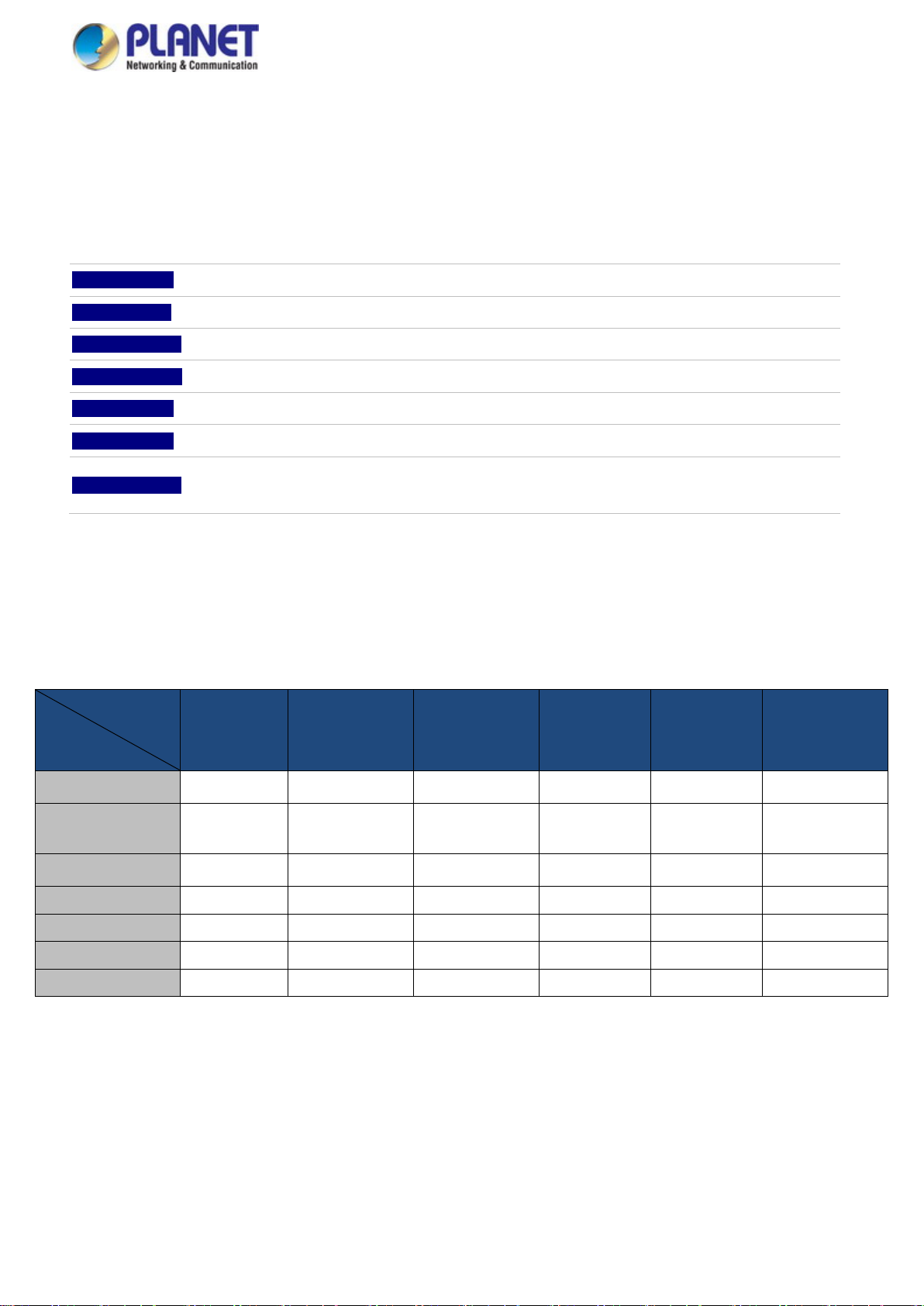
Digital Input and Digital Output for External Alarm
( IGS-10020(H)PT, IGS-12040MT, IGS-20040MT, IGS-20160HPT )
The Industrial Managed Switch supports Digital Input and Digital Output on its upper panel. The external alarm enables users to
use Digital Input to detect external device’s status (such as door intrusion detector), and send event alarm to the administrators.
The Digital Output could be used to alarm the administrators if the Industrial Managed Switch port is link-down, link-up or
power-dead.
Page 12
User’s Manual
12
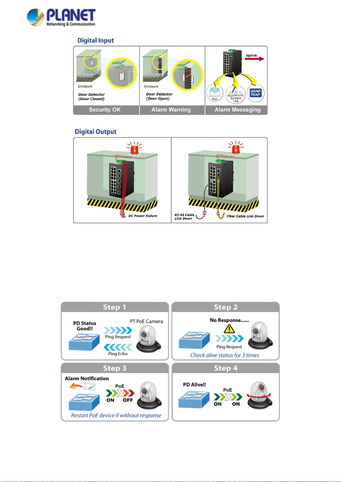
Intelligent Powered Device Alive Check (IGS-10020PT, IGS-10020HPT, IGS-20160HPT)
The Industrial Managed PoE Switch can be configured to monitor connected PD (powered device) status in real-time via ping
action. Once the PD stops working and responding, the Industrial Managed PoE Switch will recycle the PoE port power and
bring the PD back to work. It will greatly enhance the network reliability through the PoE port resetting the PD’s power source
and reduce administrator management burden.
Page 13
User’s Manual
13
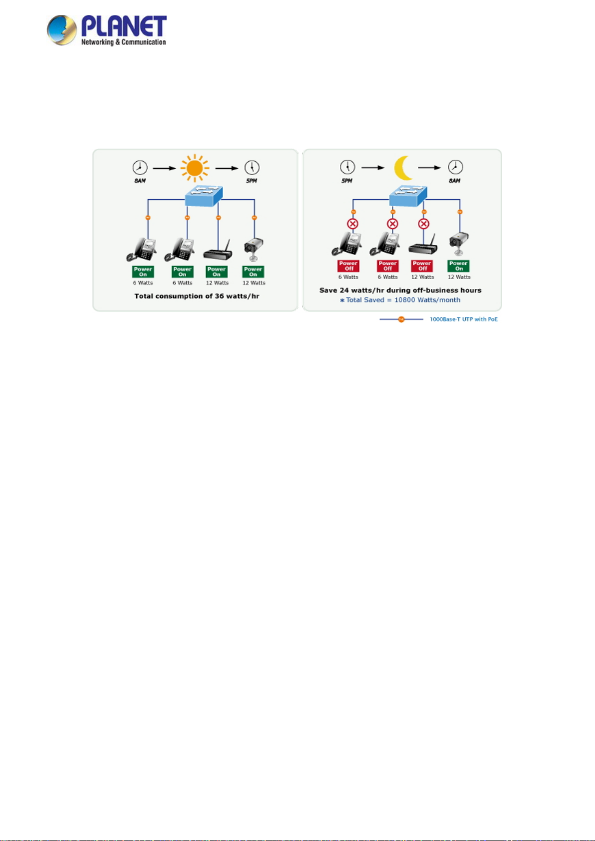
PoE Schedule for Energy Saving (IGS-10020PT, IGS-10020HPT, IGS-20160HPT)
Under the trend of energy saving worldwide and contributing to environment protection on the Earth, the Industrial Managed
PoE Switch can effectively control the power supply along with its capability of giving high watts power over Ethernet. The “PoE
schedule” function enables you to activate or inactivate PoE power feeding for each PoE port during specified time intervals,
which is a powerful function to help SMBs or enterprises save power and money.
Robust Layer2 Features
The Industrial Managed Switch can be programmed for advanced switch management function, such as dynamic port link
aggregation, Q-in-Q VLAN, Multiple Spanning Tree Protocol (MSTP), Layer 2/4 QoS, bandwidth control and IGMP/MLD
snooping. The Industrial Managed Switch allows the operation of a high-speed trunk combining multiple ports.
IPv6/IPv4 Full-function Secure Switch for Building Automation Networking
The Industrial Managed Switch is the ideal solution to fulfilling the demand of IPv6 management Gigabit Ethernet Switch,
especially in the Industrial hardened environment. It supports both IPv4 and IPv6 protocols, advanced Layer 2 to Layer 4 data
switching and redundancy, QoS traffic control, network access control and authentication, and Secure Management features to
protect customer’s industrial and building automation network connectivity with reliable switching recovery capability that is
suitable for implementing fault tolerant and mesh network architectures.
IPv4 and IPv6 VLAN Routing for Secure and Flexible Management
The Industrial Managed Switch offers IPv4/IPv6 VLAN routing feature which allows to crossover different VLANs and different IP
addresses for the purpose of having a highly-secured, flexible management and simpler networking application.
User-friendly Management Interfaces
For efficient management, the Industrial Managed Switch is equipped with console, Web and SNMP management interfaces.
With the built-in web-based management interface, the Industrial Managed Switch offers an easy-to-use, platform independent
management and configuration facility. The Industrial Managed Switch supports SNMP which can be managed via any
management software based on standard SNMP v1 or v2. For reducing product learning time, the Industrial Managed Switch
offers Cisco-like command via Telnet or console port and customer doesn’t need to learn new command from these switches.
Moreover, the Industrial Managed Switch offers remote secure management by supporting SSH, SSL and SNMPv3 connection
which can encrypt the packet content at each session.
Page 14

User’s Manual
14
Intelligent SFP Diag n o s is Mechanism
The Industrial Managed Switch supports SFP-DDM (Digital Diagnostic Monitor) function that can easily monitor real-time
parameters of the SFP for network administrator, such as optical output power, optical input power, temperature, laser bias
current, and transceiver supply voltage.
Flexible and Extendable Solution
It features 100BASE-FX and 1000BASE-SX/LX SFP (Small Form-factor Pluggable) fiber-optic modules, meaning the
administrator now can flexibly choose the suitable SFP transceiver according to the transmission distance or the transmission
speed required to extend the network efficiently.
1588 Precision Time Protocol for Industrial Computing Networks
The IGS-12040MT/IGS-20040MT/20160HPT is intended for telecom and carrier Ethernet applications, supporting MEF service
delivery and timing over packet solutions for the IEEE 1588 Precision Time Protocol and synchronous Ethernet.
Page 15

15
1.3 How to Use This Manual
This User’s Manual is structured as follows:
Section 2, INSTALLATION
The section explains the functions of the Industrial Managed Switch and how to physically install the Industrial
Managed Switch.
Section 3, SWITCH MANAGEMENT
The section contains the information about the software function of the Industrial Managed Switch.
Section 4, WEB CONFIGURATION
The section explains how to manage the Industrial Mana ge d S witch by Web interface.
Section 5, SWITCH OPERATION
The chapter explains how to do the switch operation of the Industrial Managed S witch.
Section 6, TROUBLESHOOTING
The chapter explains how to do troubleshooting of the Industrial Managed Switch.
User’s Manual
Appendix A
The section contains cable information of the Industrial Managed Switch.
Appendix B
The section contains glossary information of the Industrial Managed Switch.
Page 16

16
1.4 Product Features
Physical Port
10/100/1000BASE-T RJ45 copper
100/1000BASE-X mini-GBIC/SFP slots, SFP type auto detection
Console interface for basic management and setup (IGS-10020(H)PT, IGS-10080MFT, IGS-12040MT,
IGS-20040MT, IGS-20160HPT)
Power over Ethernet (IGS-10020(H)PT, IGS-20160HPT)
Complies with IEEE 802.3at Power over Ethernet Plus/end-span PSE
Up to 8/16 IEEE 802.3af/802.3at devices powered
Supports PoE power up to 15.4/36 watts for each PoE port
Auto detects powered device (PD)
Circuit protection prevents power interference between ports
Remote power feeding up to 100m
PoE management features
− Total PoE power budget control
− Per port PoE function enable/disable
− PoE admin-mode control
− PoE port power feeding priority
− Per PoE port power limit
− PD classification detection
Intelligent PoE features
− Temperature threshold control
− PoE usage threshold control
− PD alive check
− PoE schedule
User’s Manual
Industrial Case and Installation
IP30 aluminum case
DIN-rail and wall-mount design
− Redundant power design
Supports Ethernet ESD protection for 6000V DC
-40 to 75 degrees C operating temperature
Digital Input and Digital Output (IGS-10020(H)PT, IGS-12040MT, IGS-20040MT, IGS-20160HPT)
2 Digital Input (DI)
2 Digital Output (DO)
Integrates sensors into auto alarm system
Transfers alarm to IP network via email and SNMP trap
Layer 2 Features
High performance of Store-and-Forward architecture and runt/CRC filtering eliminates erroneous packets to optimize
Page 17

17
the network bandwidth
Storm Control support
− Broadcast/Multicast/Unknown Unicast
Supports VLAN
− IEEE 802.1Q tagged VLAN
− Up to 255 VLANs groups, out of 4095 VLAN IDs
− Provider Bridging (VLAN Q-in-Q) support (IEEE 802.1ad)
− Private VLAN Edge (PVE)
− Protocol-based VLAN
− MAC-based VLAN
− Voice VLAN
Supports Spanning Tree Protocol
− IEEE 802.1D Span ning Tree Protocol (STP)
− IEEE 802.1w Rapid Spanning Tree Protocol (RSTP)
− IEEE 802.1s Multiple Spanning Tree Protocol (MSTP) by VLAN
− BPDU Guard
Supports Link Aggregation
− 802.3ad Link Aggregation Control Protocol (LACP)
− Cisco ether-channel (static trunk)
Provides port mirror (many-to-1)
Port mirroring of the incoming or outgoing traffic on a particular port
Loop protection to avoid broadcast loops
Supports E.R.P.S. (Ethernet Ring Protection Switching)
IEEE 1588 and synchronous Ethernet network timing (IGS-12040MT, IGS-20040MT)
User’s Manual
Quality of Service
Ingress Shaper and Egress Rate Limit per port bandwidth control
8 priority queues on all switch ports
Traffic classification
- IEEE 802.1p CoS
- IP TOS/DSCP/IP Precedence
- IP TCP/UDP port number
- Typical network application
Strict priority and Weighted Round Robin (WRR) CoS policies
Supports QoS and In/Out bandwidth control on each port
Traffic-policing policies on the switch port
DSCP remarking
Multicast
Supports IPv4 IGMP snooping v1, v2 and v3
Supports IPv6 MLD snooping v1 and v2
Querier mode support
IGMP snooping port filtering
MLD snooping port filtering
MVR (Multicast VLAN Registration)
Page 18

18
Security
Authentication
− IEEE 802.1x Port-based/MAC-based network access authentication
− Built-in RADIUS client to cooperate with the RADIUS servers
− TACACS+ login users access authentication
− RADIUS/TACACS+ users access authentication
Access Control List
− IP-based Access Control List (ACL)
− MAC-based Access Control List
Source MAC/IP address binding
DHCP snooping to filter untrusted DHCP messages
Dynamic ARP Inspection discards ARP packets with invalid MAC address to IP address binding
IP Source Guard prevents IP spoofing attacks
Auto DoS rule to defend DoS attack
IP address access management to prevent unauthorized intruder
Layer 3 IP Routing Features
Supports static routes and route summarization
User’s Manual
Management
IPv4 and IPv6 dual stack management
Switch Management Interfaces
- Console/Telnet Command Line Interface
- Web switch management
- SNMP v1 and v2c switch management
- SSH/SSL and SNMP v3 secure access
IPv6 IP address/NTP/DNS management
Built-in Trivial File Transfer Protocol (TFTP) client
BOOTP and DHCP for IP address assignment
System Maintenance
− Firmware upload/download via HTTP/TFTP
− Reset button for system reboot or reset to factory default
− Dual Images
DHCP Relay and DHCP Option82
User Privilege levels control
NTP (Network Time Protocol)
Link Layer Discovery Protocol (LLDP) and LLDP-MED
SFP-DDM (Digital Diagnostic Monitor)
Network Diagnostic
− ICMPv6/ICMPv4 Remote Ping
− Cable Diagnostic technology provides the mechanism to detect and report potential cabling issues
SMTP/Syslog remote alarm
Four RMON groups (history, statistics, alarms and events)
SNMP trap for interfacing Link Up and Link Down notification
System Log
PLANET Smart Discovery Utility for deployment management
Page 19

19
Model Name
IGS-10020MT
IGS-12040MT
IGS-20040MT
Hardware Specificati ons
ports
ports
ports
(115200, 8, N, 1)
(115200, 8, N, 1)
Switch Architecture
Store-and-Forward
Switch Fabric
20Gbps/non-blocking
24Gbps/non-blocking
40Gbps/non-blocking
Throughput (packet per second)
and ageing
and ageing
and ageing
Shared Data Buffer
512 kilobytes
4Mbits
4Mbits
Back pressure for half-duplex
Jumbo Frame
> 5 sec: Factory Default
ESD Protection
6KV DC
Enclosure
IP30 aluminum case
Installation
3/4 for fault alarm; Pin 5/6
; Pin
5/6 for GND
ower 1; Pin 3/4
5/6 for GND
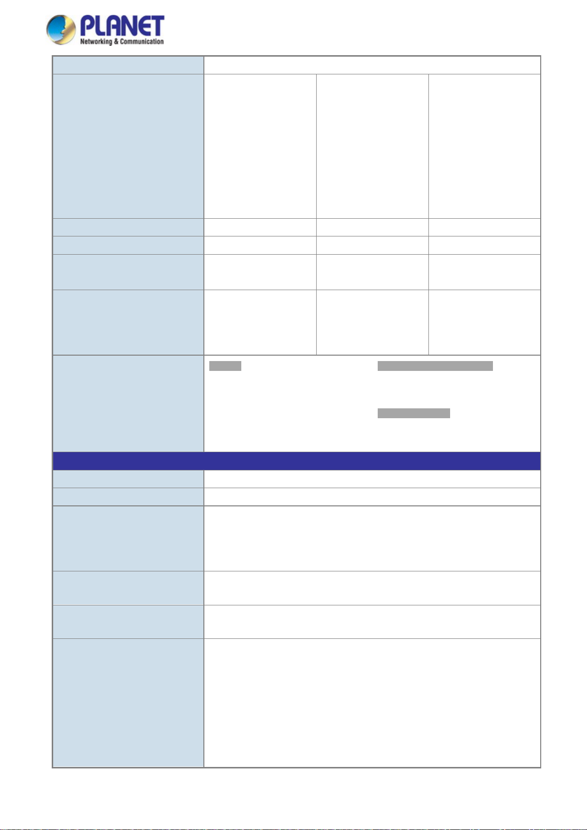
1.5 Product Specifications
IGS-10020MT/IGS-12040MT/IGS-20040MT
User’s Manual
8 10/ 100/1000BASE-T
Copper Ports
SFP/mini-GBIC Slots
Console -
Address Table
Flow Control
RJ45 Auto-MDI/MDI-X
2 1000BASE-X SFP
interfaces (Port-9 to
Port-10)
Compatible with
100BASE-FX SFP
14.8Mpps@64Bytes 17.85Mpps@64Bytes 25.6Mpps@64Bytes
8K entries, automatic
source address learning
IEEE 802.3x pause frame for full-duplex
8 10/ 100/1000BASE-T
RJ45 Auto-MDI/MDI-X
4 1000BASE-X SFP
interfaces (Port-9 to
Port-12)
Compatible with
100BASE-FX SFP
1 x RJ45 serial port
8K entries, automatic
source address learning
16 10/ 100/1000BASE-T
RJ45 Auto-MDI/MDI-X
4 1000BASE-X SFP
interfaces (Port-17 to
Port-20)
Compatible with
100BASE-FX SFP
1 x RJ45 serial port
8K entries, automatic
source address learning
Reset Button
Connector
9Kbytes
< 5 sec: System reboot
DIN rail kit and wall-mount kit
Removable 6-pin terminal
block for power input
Pin 1/2 for Power 1; Pin
3/4 for fault alarm; Pin 5/6
for Power 2
Removable 6-pin terminal
block for power input
Pin 1/2 for Power 1; Pin
for Power 2
Removable 6-pin terminal
block for DI/DO interface
Pin 1/2 for DI 0 & DI 1
3/4 for DO 0 & DO 1; Pin
Removable 6-pin terminal
block for power input
Pin 1/2 for P
for fault alarm; Pin 5/6 for
Power 2
Removable 6-pin terminal
block for DI/DO interface
Pin 1/2 for DI 0 & DI 1; Pin
3/4 for DO 0 & DO 1; Pin
Page 20
User’s Manual
20
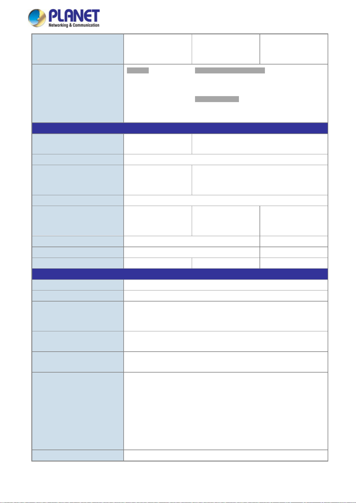
Alarm
One relay output for power failure. Alarm Relay current carry ability: 1A @ 24V AC
2 Digital Input (DI)
Level 0:
Level 1: 2.1V~24V (
Input Load to 24V DC,
10mA max.
100mA (max.)
2 Digital Input (DI)
Level 0:
Level 1: 2.1V~24V
Input Load to 24V DC,
10mA max.
100mA (max.)
Dimensions (W x D x H)
56 x 87.8 x 135mm
72 x 107 x 152mm
72 x 107 x 152mm
Weight
loading)
loading)
R.O. (Green)
100 LNK/ACT (Orange)
Layer 2 Functions
Basic Management Interfaces
Web browser; Remote Telnet; SNMPv1, v2c
Secure Management Interfac e
SSH, SSL, SNMPv3
Power saving mode control
Many to 1 monitor
Up to 255 VLAN groups, out of 4095 VLAN IDs
DI and DO -
720g 1010g 1043g
Power Requirements
Power Consumption
LED Indicator
12V to 48V DC
24V AC
10 watts/34BTU (Full
loading)
System:
Power 1 (Green)
Power 2 (Green)
Fault Alarm (Green)
Ring (Green)
:
-24V~2.1V (±0.1V)
±0.1V)
2 Digital Output (DO):
Open collector to 24V DC,
12V to 72V DC
24V AC
6.5 watts/22.18BTU
(System on)
12 watts/40.95BTU (Full
Per 10/100/1000T RJ45 Port:
1000 LNK/ACT (Green)
10/100 LNK/ACT (Orange)
Per SFP Interface:
1000 LNK/ACT (Green)
:
-24V~2.1V (±0.1V)
(±0.1V)
2 Digital Output (DO):
Open collector to 24V DC,
9V to 48V DC
24V AC
8 watts/27BTU (System
on)
17 watts/57BTU (Full
Port Configuration
Port Status
Port Mirroring
VLAN
Port disable/enable
Auto-negotiation 10/100/1000Mbps full and half duplex mode selection
Flow Control disable/enable
Display each port’s speed duplex mode, link status, Flow control status. Auto
negotiation status, trunk status.
TX/RX/Both
802.1Q tagged-based VLAN, up to 255 VLAN groups
Q-in-Q tunneling
Private VLAN Edge (PVE)
MAC-based VLAN
Protocol-based VLAN
Voice VLAN
MVR (Multicast VLAN Registration)
Page 21

User’s Manual
21
Support 5 groups of 10-Port trunk support
- DSCP/TOS field in IP Packet
IGMP Querier mode support
Up to 123 entries
Egress: 500Kb~1000Mbps
Layer 3 Functions
IP Interfaces
Routing Table
Max. 32 routing entries
IPv6 software static routing
Standards Conformance
Regulatory Compliance
IEC60068-2-6 (vibration)
RFC 791 IP
Link Aggregation
QoS
IGMP Snooping
MLD Snooping
Access Control List
Bandwidth Control
IEEE 802.3ad LACP/static trunk
Traffic classification based, strict priority and WRR
8-level priority for switching
- Port Number
- 802.1p priority
- 802.1Q VLAN tag
IGMP (v1/v2/v3) snooping, up to 255 multicast Groups
MLD (v1/v2) snooping, up to 255 multicast Groups
MLD Querier mode support
IP-based ACL/MAC-based ACL
Per port bandwidth control
Ingress: 500Kb~1000Mbps
Routing Protocols
Stability Testing
Standards Compliance
Max. 8 VLAN interfaces
IPv4 software static routing
FCC Part 15 Class A, CE
IEC60068-2-32 (free fall)
IEC60068-2-27 (shock)
IEEE 802.3 10BASE-T
IEEE 802.3u 100BASE-TX/100BASE-FX
IEEE 802.3z Gigabit SX/LX
IEEE 802.3ab Gigabit 1000BASE-T
IEEE 802.3x Flow Control and Back Pressure
IEEE 802.3ad Port Trunk with LACP
IEEE 802.1D Spanning Tree Protocol
IEEE 802.1w Rapid Spanning Tree Protocol
IEEE 802.1s Multiple Spanning Tree Protocol
IEEE 802.1p Class of Service
IEEE 802.1Q VLAN Tagging
IEEE 802.1x Port Authentication Network Control
IEEE 802.1ab LLDP
RFC 768 UDP
RFC 793 TFTP
Page 22

22
MAU-MIB
Environment
Relative Humidity: 5 ~ 95% (non-condensing)
SNMP MIBs
User’s Manual
RFC 792 ICMP
RFC 2068 HTTP
RFC 1112 IGMP version 1
RFC 2236 IGMP version 2
RFC 3376 IGMP version 3
RFC 2710 MLD version 1
FRC 3810 MLD version 2
RFC-1213 MIB-II
IF-MIB
RFC 1493 Bridge MIB
RFC 1643 Ethernet MIB
RFC 2863 Interface MIB
RFC 2665 Ether-Like MIB
RFC 2819 RMON MIB (Group 1, 2, 3 and 9)
RFC 2737 Entity MIB
RFC 2618 RADIUS Client MIB
RFC 2933 IGMP-STD-MIB
RFC 3411 SNMP-Frameworks-MIB
IEEE 802.1X PAE
LLDP
Operating
Storage
Temperature: -40 ~ 75 degrees C
Relative Humidity: 5 ~ 95% (non-condensing)
Temperature: -40 ~ 75 degrees C
Page 23

23
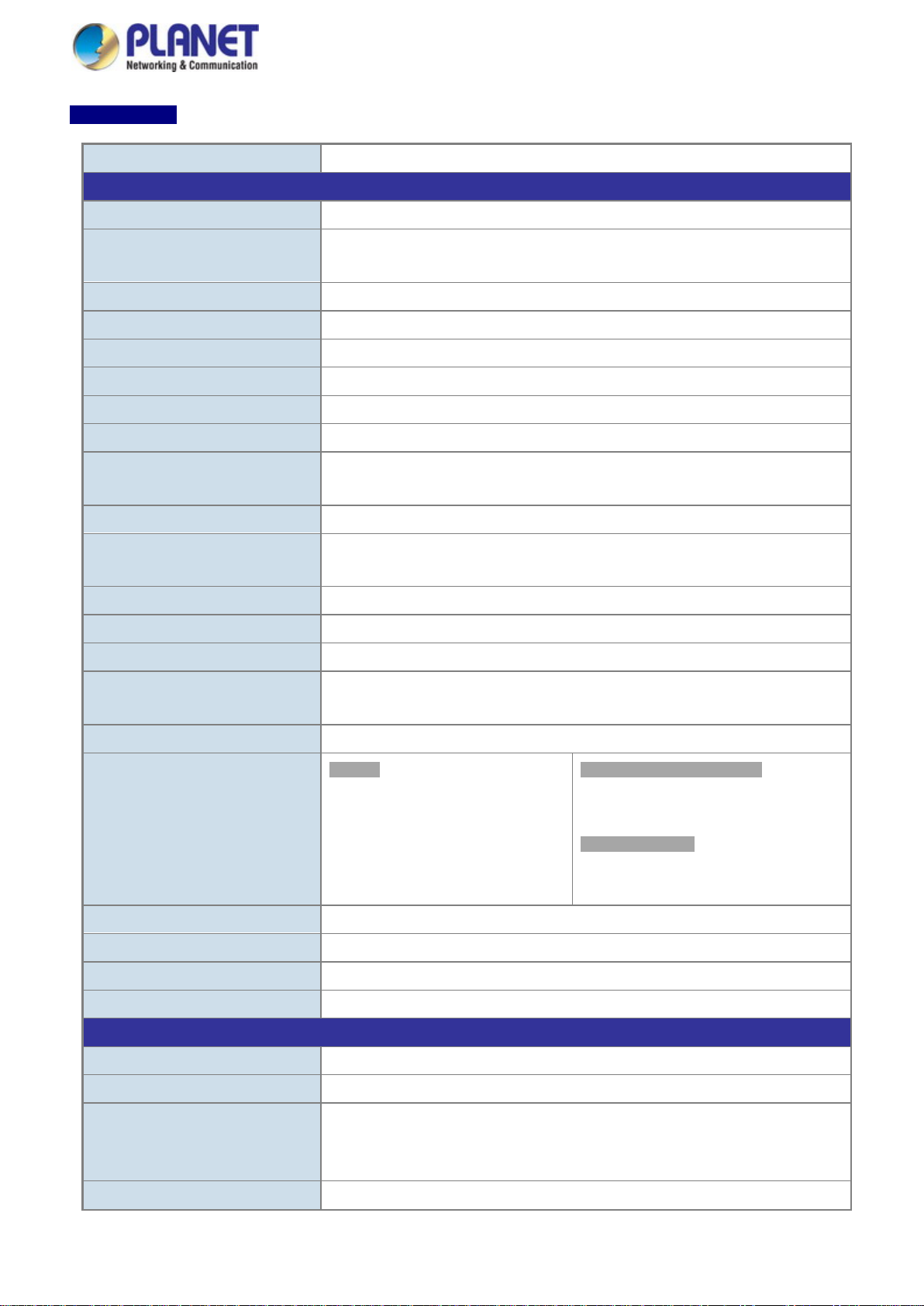
Model Name
IGS-10020PT
IGS-10020HPT
IGS-20160HPT
Hardware Specificati ons
ports
Port-1 to Port-16
Console
1 x RJ45 serial port (115200, 8, N, 1)
Switch Architecture
Store-and-Forward
Switch Fabric
Throughput (packet per second)
14.8Mpps@64Bytes
29.7Mpps@64Bytes
Address Table
8K entries, automatic source address learning and ageing
Shared Data Buffer
4Mbits
Jumbo Frame
9Kbytes
> 5 sec: Factory Default
ESD Protection
6KV DC
Enclosure
Installation
DIN rail kit and wall-mount kit
Pin 1/2 for DI 0 & DI 1; Pin 3/4 for DO 0 & DO 1; Pin 5/6 for GND
Alarm
One relay output for power failure. Alarm Relay current carry ability: 1A @ 24V AC
Dimensions (W x D x H)
72 x 107 x 152mm
84 x 107 x 152mm
Weight
1684g
1533g
Power Requirements
48V DC
48~56V DC
IGS-10020PT/IGS-10020HPT/IGS-20160HPT
Copper Ports 8 10/100/1000BASE-T RJ45 Auto-MDI/MDI-X ports
2 1000BASE-SX/LX/BX SFP interfaces (Port-9 to
SFP/mini-GBIC Slots
Port-10)
Compatible with 100BASE-FX SFP
User’s Manual
18 10/100/1000BASE-T
RJ45 Auto-MDI/MDI-X
2 1000BASE-SX/LX/BX
SFP interfaces (Port-19 to
Port-20)
Compatible with
100BASE-FX SFP
PoE Injector Ports
Flow Control
Reset Button
8 ports with 802.3at/af PoE injector function with Port-1
to Port-8
20Gbps/non-blocking 40Gbps/non-blocking
IEEE 802.3x pause frame for full-duplex
Back pressure for half-duplex
< 5 sec: System reboot
IP30 aluminum case
16 ports with 802.3at/af
PoE injector function with
Removable 6-pin terminal block for power input
Connector
DI and DO
Pin 1/2 for Power 1; Pin 3/4 for fault alarm; Pin 5/6 for Power 2
Removable 6-pin terminal block for DI/DO interface
2 Digital Input (DI): Level 0: -24V~2.1V (±0.1V)
Level 1: 2.1V~24V (±0.1V)
Input Load to 24V DC, 10mA max.
2 Digital Output (DO): Open collector to 24V DC, 100mA (max.)
Page 24
User’s Manual
24
function)
function)
function)
R.O. (Green)
1000 (Orange)
Power Over Ethernet
PoE Power Supply Type
End-span
Per Port 48V DC, 350mA .
Per Port 56V DC, 590mA. Max. 36 watts (IEEE 802.3at)
Power Pin Assignment
1/2(+), 3/6(-)
Max. number of Class 2 PDs
8
16
Max. number of Class 3 PDs
8
16
Max. number of Class 4 PDs
Not supported
8
10
Layer 2 Functions
Basic Management Interfaces
Web browser; remote Telnet; SNMPv1, v2c; local console
Secure Management Interface
SSH, SSL, SNMPv3
Flow Control disable/enable
Many to 1 monitor
Up to 255 VLAN groups, out of 4095 VLAN IDs
Link Aggregation
IEEE 802.3ad LACP/static trunk
Power Consumption
LED Indicator
PoE Standard
PoE Power Output
PoE Power Budget
161.9 watts/522.08BTU
(Full loading with PoE
System:
Power 1 (Green)
Power 2 (Green)
Fault Alarm (Green)
Ring (Green)
IEEE 802.3af Power over
Ethernet/PSE
Max. 15.4 watts
130W maximum
(depending on power
input)
306 watts/1043.46BTU
(Full loading with PoE
Per 10/100/1000T RJ45 Port:
LNK/ACT (Green)
PoE-in-Use (Orange)
Per SFP Interface:
LNK/ACT (Green)
IEEE 802.3af/IEEE 802.3at Power over Ethernet/PSE
Per Port 56V DC, 350mA . Max. 15.4 watts (IEEE
802.3af)
270W maximum
(depending on power
input)
349 watts/1190.83BTU
(Full loading with PoE
320W maximum
(depending on power
input)
Port Configuration
Port Status
Port Mirroring
VLAN
Port disable/enable
Auto-negotiation 10/100/1000Mbps full and half duplex mode selection
Display each port’s speed duplex mode, link status, flow control status, auto
negotiation status, and trunk status.
TX/RX/Both
802.1Q tagged-based VLAN, up to 255 VLAN groups
Q-in-Q tunneling
Private VLAN Edge (PVE)
MAC-based VLAN
Protocol-based VLAN
Voice VLAN
MVR (Multicast VLAN Registration)
Page 25

User’s Manual
25
Supports 5 trunk groups with 2 ports for each trunk
- DSCP/TOS field in IP packet
IGMP querier mode support
Up to 256 entries
Egress: 500Kb~1000Mbps
Layer 3 Functions
IP Interfaces
Routing Table
Max. 32 routing entries
IPv6 software static routing
Standards Conformance
Regulatory Compliance
IEC60068-2-6 (vibration)
RFC 793 TFTP
Traffic classification based, strict priority and WRR
8-level priority for switching
QoS
- Port number
- 802.1p priority
- 802.1Q VLAN tag
IGMP Snooping
MLD Snooping
Access Control List
Bandwidth Control
Routing Protocols
Stability Testing
IGMP (v1/v2/v3) snooping, up to 255 multicast Groups
MLD (v1/v2) snooping, up to 255 multicast Groups
MLD querier mode support
IP-based ACL/MAC-based ACL
Per port bandwidth control
Ingress: 500Kb~1000Mbps
Max. 8 VLAN interfaces
IPv4 software static routing
FCC Part 15 Class A, CE
IEC60068-2-32 (free fall)
IEC60068-2-27 (shock)
Standards Compliance
IEEE 802.3 10BASE-T
IEEE 802.3u 100BASE-TX/100BASE-FX
IEEE 802.3z Gigabit SX/LX
IEEE 802.3ab Gigabit 1000BASE-T
IEEE 802.3x Flow Control and Back Pressure
IEEE 802.3ad Port Trunk with LACP
IEEE 802.1D Spanning Tree Protocol
IEEE 802.1w Rapid Spanning Tree Protocol
IEEE 802.1s Multiple Spanning Tree Protocol
IEEE 802.1p Class of Service
IEEE 802.1Q VLAN Tagging
IEEE 802.1ab LLDP
IEEE 802.1x Port Authentication Network Control
IEEE 802.3af Power over Ethernet
IEEE 802.3at Power over Ethernet (IGS-10020HPT)
RFC 768 UDP
Page 26

26
Environment
Relative Humidity: 5 ~ 95% (non-condensing)
SNMP MIBs
User’s Manual
RFC 791 IP
RFC 792 ICMP
RFC 2068 HTTP
RFC 1112 IGMP version 1
RFC 2236 IGMP version 2
RFC 3376 IGMP version 3
RFC 2710 MLD version 1
FRC 3810 MLD version 2
RFC-1213 MIB-II
IF-MIB
RFC 1493 Bridge MIB
RFC 1643 Ethernet MIB
RFC 2863 Interface MIB
RFC 2665 Ether-Like MIB
RFC 2819 RMON MIB (Group 1, 2, 3 and 9)
RFC 2737 Entity MIB
RFC 2618 RADIUS Client MIB
RFC 2933 IGMP-STD-MIB
RFC 3411 SNMP-Frameworks-MIB
IEEE 802.1X PAE
LLDP
MAU-MIB
Operating
Storage
Temperature: -40 ~ 75 degrees C
Relative Humidity: 5 ~ 95% (non-condensing)
Temperature: -40 ~ 75 degrees C
Page 27
27
Model Name
IGS-10080MFT
Hardware Specificati ons
Copper Ports
2 10/ 100/1000BASE-T RJ45 Auto-MDI/MDI-X ports
Console
1 x RJ45 serial port (115200, 8, N, 1)
Switch Architecture
Store-and-Forward
Switch Fabric
20Gbps/non-blocking
Throughput (packet per second)
Address Table
8K entries, automatic source address learning and ageing
Shared Data Buffer
4Mbits
Back pressure for half-duplex
Jumbo Frame
> 5 sec: Factory Default
ESD Protection
6KV DC
Enclosure
IP30 aluminum case
Installation
Pin 1/2 for Power 1; Pin 3/4 for fault alarm; Pin 5/6 for Power 2
Alarm
One relay output for power failure. Alarm Relay current carry ability: 1A @ 24V AC
R.O. (Green)
LNK/ACT (Orange)
Dimensions (W x D x H)
Weight
1036g
Power Requirements
DC 12 to 48V, AC 24V power adapter
Power Consumption
13.92 watts/47.76BTU (full loading)
Layer 2 Functions
Basic Management Interfaces
Web browser; Remote Telnet; SNMPv1, v2c; local console
Secure Management Interfac e
SSH, SSL, SNMPv3
Flow Control disable/enable
Port Status
IGS-10080MFT
User’s Manual
SFP/mini-GBIC Slots
Flow Control
Reset Button
Connector
8 1000BASE-SX/LX/BX SFP interfaces (Port-1 to Port-8)
Compatible with 100BASE-FX SFP
14.8Mpps@64Bytes
IEEE 802.3x pause frame for full-duplex
9Kbytes
< 5 sec: System reboot
DIN-rail kit and wall-mount kit
Removable 6-pin terminal block for power input
LED Indicator
Port Configuration
System:
Power 1 (Green)
Power 2 (Green)
Fault Alarm (Green)
Ring (Green)
72 x 107 x 152mm
Port disable/enable
Auto-negotiation 10/100/1000Mbps full and half duplex mode selection
Display each port’s speed duplex mode, link status, flow control status, auto
Per 10/100/1000T RJ45 Port:
1000 (Green)
LNK/ACT (Orange)
Per SFP Interface:
1000 (Green)
Page 28

User’s Manual
28
negotiation status, and trunk status.
Many to 1 monitor
Up to 255 VLAN groups, out of 4095 VLAN IDs
- DSCP/TOS field in IP Packet
IGMP Querier mode support
MLD Querier mode support
Egress: 500Kb~1000Mbps
Layer 3 Functions
IP Interfaces
Max. 8 VLAN interfaces
Routing Table
Routing Protocols
IPv4 software static routing; IPv6 software static routing
Standards Conformance
Regulatory Compliance
FCC Part 15 Class A, CE
Stability Testing
IEEE 802.1w Rapid Spanning Tree Protocol
Port Mirroring
VLAN
Link Aggregation
QoS
TX/RX/Both
802.1Q tagged-based VLAN, up to 255 VLAN groups
Q-in-Q tunneling
Private VLAN Edge (PVE)
MAC-based VLAN
Protocol-based VLAN
Voice VLAN
MVR (Multicast VLAN Registration)
IEEE 802.3ad LACP/static trunk
Supports 5 trunk groups with 8 ports for each trunk
Traffic classification based, strict priority and WRR
8-level priority for switching
- Port Number
- 802.1p priority
- 802.1Q VLAN tag
IGMP Snooping
MLD Snooping
Access Control List
Bandwidth Control
Standards Compliance
IGMP (v1/v2/v3) Snooping, up to 255 multicast groups
MLD (v1/v2) Snooping, up to 255 multicast Groups
IP-based ACL / MAC-based ACL
Up to 256 entries
Per port bandwidth control
Ingress: 500Kb~1000Mbps
Max. 32 routing entries
IEC60068-2-32 (free fall) , IEC60068-2-27 (shock) , IEC60068-2-6 (vibration)
IEEE 802.3 10BASE-T
IEEE 802.3u 100BASE-TX/100BASE-FX
IEEE 802.3z Gigabit SX/LX
IEEE 802.3ab Gigabit 1000BASE-T
IEEE 802.3x Flow Control and Back Pressure
IEEE 802.3ad Port Trunk with LACP
IEEE 802.1D Spanning Tree Protocol
Page 29

User’s Manual
29
Environment
Relative Humidity: 5 ~ 95% (non-condensing)
IEEE 802.1s Multiple Spanning Tree Protocol
IEEE 802.1p Class of Service
IEEE 802.1Q VLAN Tagging
IEEE 802.1x Port Authentication Network Control
IEEE 802.1ab LLDP
RFC 768 UDP
RFC 793 TFTP
RFC 791 IP
RFC 792 ICMP
RFC 2068 HTTP
RFC 1112 IGMP version 1
RFC 2236 IGMP version 2
RFC 3376 IGMP version 3
RFC 2710 MLD version 1
FRC 3810 MLD version 2
SNMP MIBs
Operating
Storage
RFC-1213 MIB-II
IF-MIB
RFC 1493 Bridge MIB
RFC 1643 Ethernet MIB
RFC 2863 Interface MIB
RFC 2665 Ether-Like MIB
RFC 2737 Entity MIB
RFC 2618 RADIUS Client MIB
RFC 2933 IGMP-STD-MIB
RFC 3411 SNMP-Frameworks-MIB RFC 2819 RMON MIB (Group 1, 2, 3 and 9)
IEEE 802.1X PAE
LLDP
MAU-MIB
Temperature: -40 ~ 75 degrees C
Relative Humidity: 5 ~ 95% (non-condensing)
Temperature: -40 ~ 75 degrees C
Page 30
User’s Manual
30
2. INSTALLATION
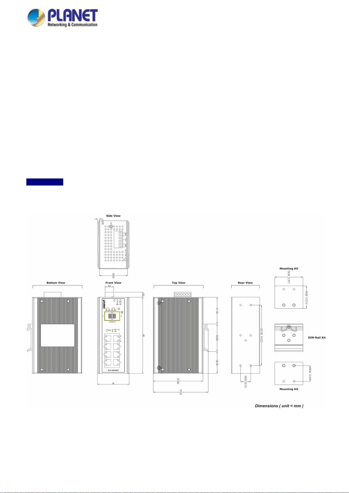
2.1 Hardware Description
The Industrial Managed Switch provides three different running speeds – 10Mbps, 100Mbps and 1000Mbps and automatically
distinguishes the speed of incoming connection.
This section describes the hardware features of Industrial Managed Switch. For easier management and control of the Industrial
Managed Switch, familiarize yourself with its display indicators and ports. Front panel illustrations in this chapter display the unit
LED indicators. Before connecting any network device to the Industrial Managed Switch, read this chapter carefully.
2.1.1 Physical Dimensions
IGS-10020MT
IGS-10020MT
Dimensions (W x D x H) : 56 x 87.8 x 135mm
Page 31

31
IGS-10020PT
IGS-10020PT
Dimensions (W x D x H) : 72 x 107 x 152mm
User’s Manual
Page 32

32
IGS-10020HPT
IGS-10020HPT
Dimensions (W x D x H) : 72 x 107 x 152mm
User’s Manual
Page 33

33
IGS-10080MFT
IGS-10080MFT
Dimensions (W x D x H) : 72 x 107x 152mm
User’s Manual
Page 34

34
IGS-12040MT
IGS-12040MT
Dimensions (W x D x H) : 72 x 107 x 152mm
User’s Manual
Page 35

35
IGS-20040MT
IGS-20040MT
Dimensions (W x D x H) : 72 x 107 x 152mm
User’s Manual
Page 36

36
IGS-20160HPT
IGS-20160HPT
Dimensions (W x D x H) : 84 x 107 x 152mm
User’s Manual
Page 37

37
2.1.2 Front Panel
IGS-10020MT IGS-10020PT IGS-10020HPT
User’s Manual
Figure 2-1:
IGS-10020MT Switch Front Panel
Figure 2-2:
IGS-10020PT Switch Front Panel
IGS-10020HPT Switch Front Panel
Figure 2-3:
Page 38

User’s Manual
38
IGS-100080MFT IGS-12040MT IGS-20040MT
Figure 2-4:
IGS-10080MFT Switch Front Panel
Figure 2-5:
IGS-12040MT Switch Front Panel
Figure 2-6:
IGS-20040MT Switch Front Panel
Page 39

User’s Manual
39
IGS-20160HPT
Figure 2-7:
IGS-20160HPT Switch Front Panel
■ Gigabit TP Interface
10/100/1000BASE-T Copper, RJ45 Twist ed-pair: Up to 100 meters.
■ SFP Slot
100/1000BASE-X mini-GBIC slot, SFP (Small-form Factor Pluggable) transceiver module: From 550 meters to 2km
(multi-mode fiber) and to 10/20/30/40/50/70/120 kilometers (single-mode fiber).
■ Console Port
The console port is an RJ45 port connector. It is an interface for connecting a terminal directly. Through the console port, it
provides rich diagnostic information including IP address setting, factory reset, port management, link status and system
setting. Users can use the attached DB9 to RJ45 console cable in the package and connect to the console port on the
device. After the connection, users can run any terminal emulation program (Hyper Terminal, ProComm Plus, Telix,
Winterm and so on) to enter the startup screen of the device.
Page 40

User’s Manual
40
Console interface is not availa
ble for the IGS-10020MT.
■ Reset button
On the upper left side of the front panel, the reset button is designed for rebooting the Industrial Managed Switch without
turning off and on the power. The following is the summary table of reset button functions:
IGS-10020MT IGS-10020PT/IGS-10020HPT IGS-20160HPT
Figure 2-8:
IGS-10020MT Reset Button
IGS-10080MFT IGS-12040MT IGS-20040MT
Figure 2-9:
IGS-10020PT/IGS-10020HPT Reset
Button
Figure 2-10:
IGS-20160HPT Reset Button
Figure 2-11:
IGS-10080MFT Reset Button
Figure 2-12:
IGS-12040MT Reset Button
Figure 2-13:
IGS-20040MT Reset Button
Page 41

41
Reset Button Pressed and Released
Function
configuration. The Industrial Managed Switch will then reboot
Default Gateway: 192.168.0.254
port.
Indicates that the port is successfully connecting to the network at
1000Mbps.
< 5 sec: System Reboot Reboot the Industrial Managed Switch.
> 5 sec: Factory Default
2.1.3 LED Indications
User’s Manual
Reset the Industrial Managed Switch to Factory Default
and load the default settings as shown below:
。 Default Username: admin
。 Default Password: admin
。 Default IP address: 192.168.0.100
。 Subnet mask: 255.255.255.0
。
IGS-10020MT
System
LED Color Function
P1 Green Indicates power 1 has power.
P2 Green
Fault Green Indicates either power 1 or power 2 has no power.
On Indicates the ERPS Ring has been created successfully.
Ring
Off Indicates the ERPS Ring hasn’t been created.
Green
R.O.
Off Indicates the Ring Owner hasn’t been enabled.
Per 10/100/1000BASE-T Port
Indicates power 2 has power.
Indicates the Ring Owner has been enabled.
LED Color Function
Lights
LNK/ACT Green
Blinks
Lights
1000 Orange
Off
Indicates the link through that port is successfully established.
Indicates that the Switch is actively sending or receiving data over that
Indicates that the port is successfully connecting to the network at
10Mbps or 100Mbps.
Page 42

42
Indicates that the Switch is actively sending or receiving data over that
port.
Lights
Off:
Per SFP Interface
LED Color Function
User’s Manual
Lights
LNK/ACT Green
Blinks
Lights
1000 Orange
Off
Indicates the link through that port is successfully established.
Indicates that the port is successfully connecting to the network at
1000Mbps.
Indicates that the port is successfully connecting to the network at
100Mbps.
IGS-10020PT/IGS-10020HPT/IGS-20160HPT
System
LED Color Function
P1 Green
P2 Green
Fault Green Lights to indicate Power failure
Ring Green Lights to indicate that the ERPS Ring has been created successfully.
Lights to indicate that the Switch has power.
Lights to indicate that the Switch has power.
R.O. Green Lights to indicate that the Ring Owner has been enabled.
Per 10/100/1000Mbps Port with PoE
LED Color Function
10/100/1000
Green
LNK/ACT
PoE-in-Use Orange
SFP 100/1000Mbps (Port-9, Port-10 mini-GBIC)
LED Color Function
LNK/ACT Green
Lights to indicate the port is running in 10/100/1000Mbps speed and successfully
established.
Blinks: indicates that the switch is actively sending or receiving data over that port.
Lights
Blinks Indicates that the Switch is actively sending or receiving data over that port.
: To indicate the port is providing 56V DC in-line power.
To indicate the connected device is not a PoE Powered Device (PD).
Indicates the link through that port is successfully established.
Lights Indicates that the port is successfully connecting to the network at 1000Mbps.
1000 Orange
Off Indicates that the port is successfully connecting to the network at 100Mbps.
Page 43

43
Indicates that the Switch is actively sending or receiving data over that
port.
Indicates that the port is successfully connecting to the network at
1000Mbps.
port.
IGS-10080MFT
System
LED Color Function
P1 Green Indicates power 1 has power.
P2 Green Indicates power 2 has power.
Fault Green Indicates either power 1 or power 2 has no power.
Ring
R.O.
User’s Manual
On Indicates the ERPS Ring has been created successfully.
Off Indicates the ERPS Ring hasn’t been created.
Green Indicates the Ring Owner has been enabled.
Off Indicates the Ring Owner hasn’t been enabled.
Per 10/100/1000BASE-T Port
LED Color Function
Lights
LNK/ACT Green
1000 Orange
Per SFP Interface
LED Color Function
1000
Green
LNK/ACT
100
Orange
LNK/ACT
Blinks
Lights
Off
Lights
Blinks
Lights
Blinks
Indicates the link through that port is successfully established.
Indicates that the port is successfully connecting to the network at 10 /
100Mbps.
Indicates the link through that port is successfully established.
Indicates that the Switch is actively sending or receiving data over that
Indicates that the port is successfully connecting to the network at
100Mbps.
Indicates that the Switch is actively sending or receiving data over that
port.
Page 44

44
IGS-12040MT/IGS-20040MT
LED Definition:
System
LED Color Function
P1 Green Indicates power 1 has power.
P2 Green Indicates power 2 has power.
Fault Green Indicates either power 1 or power 2 has no power.
Ring Green Lights to indicate that the ERPS Ring has been created successfully.
R.O. Green Lights to indicate that the Ring Owner has been enabled.
Per 10/100/1000BASE-T Port
LED Color Function
User’s Manual
1000
LNK/ACT
10/100
LNK/ACT
Per SFP Interface
LED Color Function
1000
LNK/ACT
100
LNK/ACT
Lights
Indicates the port is running in 1000Mbps speed and successfully
established.
Green
Indicates that the switch is actively sending or receiving data over that
Blinks
port.
Indicates the port is running in 10/100Mbps speed and successfully
Lights
established.
Orange
Indicates that the switch is actively sending or receiving data over that
Blinks
port.
Indicates the port is running in 1000Mbps speed and successfully
Lights
established.
Green
Indicates that the switch is actively sending or receiving data over that
Blinks
port.
Indicates the port is running in 100Mbps speed and successfully
Lights
established.
Orange
Indicates that the switch is actively sending or receiving data over that
Blinks
port.
Page 45

User’s Manual
45
2.1.4 Switch Upper Panel
The Upper Panel of the Industrial Managed Switch comes with a DC inlet power socket and one terminal block connector with
6 contacts.
1. Insert positive/negative DC power wires into contacts 1 and 2 for DC Power 1, or 5 and 6 for DC Power 2.
Figure 2-14: IGS-10020MT Upper Panel
Figure 2-15: IGS-10020PT/HPT Upper Panel
Page 46

User’s Manual
46
Figure 2-16: IGS-10080MFT Upper Panel
Figure 2-17: IGS-12040MT Upper Panel
Page 47

User’s Manual
47
Figure 2-18: IGS-20040MT Upper Panel
Figure 2-19: IGS-20160HPT Upper Panel
Page 48

48
1 2 3 4 5 6 DC 1
DC 2
2. Tighten the wire-clamp screws for preventing the wires from loosening.
Figure 2-20 6-Pi n Te rminal Block Power Wiring Input
Model Name Positive (+) Pin Negative (-) Pin Input Voltage
IGS-10020MT Pin 2/6 Pin 1/5 DC 12~48V, AC 24V
User’s Manual
IGS-10020PT/HPT Pin 1/6 Pin 2/5 DC 48V
IGS-10020HPT Pin 1/5 Pin 2/6 DC 48V
IGS-10080MFT Pin 1/5 Pin 2/6 DC 12~48V, AC 24V
IGS-12040MT Pin 1/5 Pin 2/6 DC 12~72V, AC 24V
IGS-20040MT Pin 1/5 Pin 2/6 DC 9~48V, AC 24V
IGS-20160HPT Pin 1/5 Pin 2/6 DC 48~56V, AC 24V
1. The wire gauge for the terminal block should be in the range of 12 ~ 22 AWG@25 degrees C.
2. When performing any of the procedures like inserting the wires or tightening the wire-clamp screws,
make sure the power is OFF to prevent from getting an electric shock.
Page 49

User’s Manual
49
2.1.5 Wiring the Fault Alarm Contact
The fault alarm contacts are in the middle (3 & 4) of the terminal block connector as the picture shows below. Inserting the wires,
the Industrial Managed Switch will detect the fault status of the power failure, or port link failure (available for managed model).
The following illustration shows an application example for wiring the fault alarm contacts
Insert the wires into the fault alarm contacts
1. The wire gauge for the terminal block should be in the range of 12 ~ 24 AWG.
2. When performing any of the procedures like inserting the wires or tightening the wire-clamp screws,
make sure the power is OFF to prevent from getting an electric shock.
2.1.6 Wiring the Digital Input/Output
The 6-contact terminal block connector on the rear panel of IGS Series is used for Digital Input and Digital Output. Please follow
the steps below to insert wire.
1. The IGS-10020PT/10020HPT/12040MT/20040MT offers two DI and DO groups. 1 and 2 are DI groups; 3 and 4 are DO
groups; and 5 and 6 are GND (ground).
Figure 2-21 Wiring the Redundant Power Inputs
Page 50

User’s Manual
50
1 2 3 4 5
6
2. Tighten the wire-clamp screws for preventing the wires from loosening.
DI0 DI1 DO0 DO1 GND GND
Figure 2-22 6-pin Terminal Block for DI and DO Wiring Input
3. There are two Digital Input groups for you to monitor two different devices. The following topology shows how to wire DI0
and DI1.
Figure 2-23 Wires DI0 and DI1 to Open Detector
Page 51

User’s Manual
51
4. There are two Digital Output groups for you to sense IGS-10020PT/10020HPT/12040MT/20040MT/20160HPT port failure
or power failure and issue a high or low signal to external device. The following topology shows how to wire DO0 and
DO1.
Figure 2-24 Wires DO0 and DO1 to Open Detector
2.2 Installing the Industrial Managed Switch
This section describes how to install your Industrial Managed Switch and make connections to the Industrial Managed
Switch. Please read the following topics and perform the procedures in the order being presented. To install your Industrial
Managed Switch on a desktop or shelf, simply complete the following steps.
In this paragraph, we will describe how to install the Industrial Managed Switch and the installation points attended to it.
2.2.1 Installation Steps
1. Unpack the Industrial Managed Switch
2. Check if the DIN-Rail is screwed on the Industrial Managed Switch or not. If the DIN-Rail is not screwed on the
Industrial Managed Switch, please refer to DIN-rail Mounting section for DIN-rail installation. If users want to
wall-mount the Industrial Managed Switch, please refer to the Wall Mount Plate Mounting section for wall-mount plate
installation.
3. To hang the Industrial Managed Switch on the DIN-rail track or wall.
4. Power on the Industrial Managed Switch. Please refer to the Wiring the Power Inputs section for knowing the
information about how to wire the power. The power LED on the Industrial Managed Switch will light up. Please refer to
the LED Indicators section for indication of LED lights.
5. Prepare the twisted-pair, straight-through Category 5 cable for Ethernet connection.
Page 52

User’s Manual
52
6. Insert one side of RJ45 cable (category 5) into the Industrial Managed Switch Ethernet port (RJ45 port) while the
other side to the network device’s Ethernet port (RJ45 port), e.g., Switch PC or Server. The UTP port (RJ45) LED on the
Industrial Managed Switch will light up when the cable is connected with the network device. Please refer to the LED
Indicators section for LED light indication.
Make sure that the connected network devices support MDI/MDI-X. If it does not support,
use the crossover Category 5 cable.
7. When all connections are set and all LED lights show normal, the installation is completed.
Page 53

User’s Manual
53
2.2.2 DIN-rail Mounting
This section describes how to install the Industrial Managed Switch. There are two methods to install the Industrial Managed
Switch -- DIN-rail mounting and wall-mount plate mounting. Please read the following topics and perform the procedures in the
order being presented.
Follow all the DIN-rail installation steps as shown in the example.
Step 1: Screw the DIN-rail on the Industrial Managed Switch.
Step 2: Lightly slide the DIN-rail into the track.
Page 54

54
Step 3: Check whether the DIN-rail is tightly on the track.
Please refer to the following procedures to remove the Industrial Managed Switch from the track.
Step 4: Lightly remove the DIN-rail from the track.
User’s Manual
Page 55

User’s Manual
55
2.2.3 Wall Mount Plate Mounting
To install the Industrial Managed Switch on the wall, please follow the instructions below.
Follow all the DIN-rail installation steps as shown in the example.
Step 1: Remove the DIN-rail from the Industrial Managed Switch. Use the screwdriver to loosen the screws to remove the
DIN-rail.
Step 2: Place the wall-mount plate on the rear panel of the Industrial Managed Switch.
Step 3: Use the screwdriver to screw the wall mount plate on the Industrial Managed Switch.
Step 4: Use the hook holes at the corners of the wall mount plate to hang the Industrial Managed Switch on the wall.
Step 5: To remove the wall mount plate, reverse the steps above.
Page 56

User’s Manual
56
Port Type
Cable Type
Connector
10BASE-T
Cat3, 4, 5, 2-pair
RJ45
100BASE-TX
Cat5 UTP, 2-pair
RJ45
1000BASE-T
Cat5/5e/6 U T P, 2 -pair
RJ45
50/125µm or 62.5/125µm multi-mode 9/125µm single-mode
LC
1000BASE-SX/LX
50/125µm or 62.5/125µm multi-mode 9/125µm single-mode
LC (multi/single mode)
2.3 Cabling
10/100/1000BASE-T
All 10/100/1000BASE-T ports come with auto-negotiation capability. They automatically support 1000BASE-T,
100BASE-TX and 10BASE-T networks. Users only need to plug a working network device into one of the
10/100/1000BASE-T ports, and then turn on the Industrial Managed Switch. The port will automatically run in 10Mbps,
20Mbps, 100Mbps or 200Mbps and 1000Mbps or 2000Mbps after negotiating with the connected device.
100BASE-FX/1000BASE-SX/LX
The Industrial Managed Switch has four SFP interfaces that support 100/1000Mbps dual speed mode (optional
multi-mode/single-mode 100BASE-FX/1000BASE-SX/LX SFP module)
Cabling
Each 10/100/1000BASE-T port uses an RJ45 socket -- similar to phone jacks -- for connection of unshielded twisted-pair
cable (UTP). The IEEE 802.3/802.3u 802.3ab Fast/Gigabit Ethernet standard requires Category 5 UTP for 100Mbps
100BASE-TX. 10BASE-T networks can use Cat.3, 4, 5 or 1000BASE-T use 5/5e/6 UTP (see table below). Maximum
distance is 100 meters (328 feet). The 100BASE-FX/1000BASE-SX/LX SFP slot uses an LC connector with optional SFP
module. Please see table below and know more about the cable specifications.
100BASE-FX
Any Ethernet devices like hubs and PCs can connect to the Industrial Managed Switch by using straight-through wires.
The two 10/100/1000Mbps ports are auto-MDI/MDI-X and can be used on straight-through or crossover cable.
(multi/single mode)
Page 57

User’s Manual
57
MFB-FX
100
LC
Multi Mode
2km
1310nm
0 ~ 60 degrees C
MFB-F20
100
LC
Single Mode
20km
1310nm
0 ~ 60 degrees C
MFB-F40
100
LC
Single Mode
40km
1310nm
0 ~ 60 degrees C
MFB-F60
100
LC
Single Mode
60km
1310nm
0 ~ 60 degrees C
MFB-F120
100
LC
Single Mode
120km
1550nm
0 ~ 60 degrees C
MFB-TFX
100
LC
Multi Mode
2km
1310nm
-40 ~ 75 degrees C
MFB-TF20
100
LC
Single Mode
20km
1550nm
-40 ~ 75 degrees C
2.3.1 Installing the SFP Transceiver
The sections describe how to insert an SFP transceiver into an SFP slot. The SFP transceivers are hot-pluggable and
hot-swappable. You can plug in and out the transceiver to/from any SFP port without having to power down the Industrial
Managed Switch as Figure 2-25 appears.
Figure 2-25: Plug in the SFP Transceiver
Approved PLANET SFP Transceivers
PLANET Industrial Managed Switch supports 100/1000 dual mode with both single mode and multi-mode SFP
transceivers. The following list of approved PLANET SFP transceivers is correct at the time of publication:
Fast Ethernet Transceiver (100BASE-X SFP)
Model Speed (Mbps)
Connector
Interface
Fiber Mode Distance Wavelength (nm) Operating Temp.
Page 58

58
Speed (Mbps)
Connector
Interface
Wavelength
(TX)
Wavelength
(RX)
MFB-FA20
100
WDM(LC)
Single Mode
20km
1310nm
1550nm
0 ~ 60 degrees C
MFB-FB20
100
WDM(LC)
Single Mode
20km
1550nm
1310nm
0 ~ 60 degrees C
MFB-TFA20
100
WDM(LC)
Single Mode
20km
1310nm
1550nm
-40 ~ 75 degrees C
MFB-TFB20
100
WDM(LC)
Single Mode
20km
1550nm
1310nm
-40 ~ 75 degrees C
MFB-TFA40
100
WDM(LC)
Single Mode
40km
1310nm
1550nm
-40 ~ 75 degrees C
MFB-TFB40
100
WDM(LC)
Single Mode
40km
1550nm
1310nm
-40 ~ 75 degrees C
Connector
Interface
MGB-GT
1000
Copper
--
100m
--
0 ~ 60 degrees C
MGB-SX2
1000
LC
Multi Mode
2km
1310nm
0 ~ 60 degrees C
MGB-L30
1000
LC
Single Mode
30km
1310nm
0 ~ 60 degrees C
MGB-L70
1000
LC
Single Mode
70km
1550nm
0 ~ 60 degrees C
MGB-TSX
1000
LC
Multi Mode
550m
850nm
-40 ~ 75 degrees C
MGB-TL30
1000
LC
Single Mode
30km
1310nm
-40 ~ 75 degrees C
Connector
Interface
MGB-LA10
1000
WDM(LC)
Single Mode
10km
1310nm
1550nm
0 ~ 60 degrees C
MGB-LB10
1000
WDM(LC)
Single Mode
10km
1550nm
1310nm
0 ~ 60 degrees C
MGB-LA20
1000
WDM(LC)
Single Mode
20km
1310nm
1550nm
0 ~ 60 degrees C
MGB-LB20
1000
WDM(LC)
Single Mode
20km
1550nm
1310nm
0 ~ 60 degrees C
MGB-LA40
1000
WDM(LC)
Single Mode
40km
1310nm
1550nm
0 ~ 60 degrees C
MGB-LB40
1000
WDM(LC)
Single Mode
40km
1550nm
1310nm
0 ~ 60 degrees C
MGB-LA60
1000
WDM(LC)
Single Mode
60km
1310nm
1550nm
0 ~ 60 degrees C
MGB-LB60
1000
WDM(LC)
Single Mode
60km
1550nm
1310nm
0 ~ 60 degrees C
MGB-TLA10
1000
WDM(LC)
Single Mode
10km
1310nm
1550nm
-40 ~ 75 degrees C
MGB-TLB10
1000
WDM(LC)
Single Mode
10km
1550nm
1310nm
-40 ~ 75 degrees C
MGB-TLA20
1000
WDM(LC)
Single Mode
20km
1310nm
1550nm
-40 ~ 75 degrees C
MGB-TLB20
1000
WDM(LC)
Single Mode
20km
1550nm
1310nm
-40 ~ 75 degrees C
MGB-TLA40
1000
WDM(LC)
Single Mode
40km
1310nm
1550nm
-40 ~ 75 degrees C
MGB-TLB40
1000
WDM(LC)
Single Mode
40km
1550nm
1310nm
-40 ~ 75 degrees C
MGB-TLA60
1000
WDM(LC)
Single Mode
60km
1310nm
1550nm
-40 ~ 75 degrees C
MGB-TLB60
1000
WDM(LC)
Single Mode
60km
1550nm
1310nm
-40 ~ 75 degrees C
Fast Ethernet Transceiver (100BASE-BX, Single Fiber Bi-directional SFP)
User’s Manual
Model
Gigabit Ethernet Transceiver (1000BASE-X SFP)
Model Speed (Mbps)
MGB-SX 1000 LC Multi Mode 550m 850nm 0 ~ 60 degrees C
MGB-LX 1000 LC Single Mode 10km 1310nm 0 ~ 60 degrees C
MGB-L50 1000 LC Single Mode 50km 1550nm 0 ~ 60 degrees C
Fiber Mode Distance
Operating Temp.
Fiber Mode Distance Wavelength (nm) Operating Temp.
MGB-L120 1000 LC Single Mode 120km 1550nm 0 ~ 60 degrees C
MGB-TLX 1000 LC Single Mode 10km 1310nm -40 ~ 75 degrees C
MGB-TL70 1000 LC Single Mode 70km 1550nm -40 ~ 75 degrees C
Gigabit Ethernet Transceiver (1000BASE-BX, Single Fiber Bi-directional SFP)
Model Speed (Mbps)
Fiber Mode Distance Wavelength (TX) Wavelength (RX) Operating Temp.
Page 59

User’s Manual
59
It is recommended to use PLANET SFPs on the Industrial Managed Switch. If you insert an
SFP transceiver that is not supported, the Industrial Managed Switch might not recognize it.
Please choose the SFP transceiver which can be operated in the temperature range of -40~75
degrees C.
1000BASE-SX/LX:
Before connecting the other switches, workstation or media converter,
1. Make sure both sides of the SFP transceiver are with the same media type, for example, 1000BASE-SX to 1000BASE-SX,
1000BASE-LX to 1000BASE-LX.
2. Check whether the fiber-optic cable type matches the SFP transceiver model.
To connect to 1000BASE-SX SFP transceiver, use the multi-mode fiber cable -- with one side being the male duplex
LC connector type.
To connect to 1000BASE-LX SFP transceiver, use the single-mode fiber cable -- with one side being the male duplex
LC connector type.
Connect the fiber cable
1. Attach the duplex LC connector on the network cable to the SFP transceiver.
2. Connect the other end of the cable to a device – switches with SFP installed, fiber NIC on a workstation or a media
converter.
3. Check the LNK/ACT LED of the SFP slot on the front of the Industrial Managed Switch. Ensure that the SFP transceiver
is operating correctly.
100BASE-FX:
Before connecting the other switches, workstation or media converter,
1. Make sure both sides of the SFP transceiver are with the same media type or WDM pair, for example, 100BASE-FX to
100BASE-FX, 100BASE-BX20-U to 100BASE-BX20-D.
2. Check whether the fiber-optic cable type matches the SFP transceiver model.
To connect to MFB-FX SFP transceiver, use the multi-mode fiber cable -- with one side being the male duplex LC
connector type.
To connect to MFB-F20/F40/F60/FA20/FB20 SFP transceiver, use the single-mode fiber cable -- with one side being
the male duplex LC connector type.
Connect the fiber cable
1. Attach the duplex LC connector on the network cable to the SFP transceiver.
2. Connect the other end of the cable to a device – switches with SFP installed, fiber NIC on a workstation or a media
converter.
3. Check the LNK/ACT LED of the SFP slot of the switch/converter. Ensure that the SFP transceiver is operating correctly.
4. Check the Link mode of the SFP port if the link fails. It can function with some fiber-NICs or media converters, and set the
Link mode to “100 Force” when needed.
Page 60

User’s Manual
60
2.3.2 Removing the SFP Transceiver
1. Make sure there is no network activity by consulting or checking with the network administrator. Or through the
management interface of the switch/converter (if available) to disable the port in advance.
2. Remove the fiber optic cable gently.
3. Turn the lever of the MGB/MFB module to a horizontal position.
4. Pull out the module gently through the lever.
Figure 2-26: Pull out the SFP Transceiver Module
Never pull out the module without pulling the lever or the push bolts on the module. Directly pulling
out the module with force could damage the module and SFP module slot of the device.
Page 61

User’s Manual
61
3. SWITCH MANAGEMENT
This chapter explains the methods that you can use to configure management access to the Industrial Managed Switch. It
describes the types of management applications and the communication and management protocols that deliver data between
your management device (workstation or personal computer) and the system. It also contains information about port connection
options.
This chapter covers the following topics:
Requirements
Management Access Overview
Remote Telnet Access
Web Management Access
SNMP Access
Standards, Protocols, and Related Reading
3.1 Requirements
Workstation running Windows XP/2003, Vista, Windows 7/8/10, MAC OS X, Linux, Fedora, Ubuntu or other
platform is compatible with TCP/IP protocols.
Workstation is installed with Ethernet NIC (Network Interface Card)
Serial Port (Terminal)
• The above PC comes with COM Port (DB9/RS232) or USB-to-RS232 converter
Ethernet Port
• Network cables -- Use standard network (UTP) cables with RJ45 connectors.
The above workstation is installed with Web browser and JAVA runtime environment Plug-in
It is recommended to use Internet Explore 8.0 or above to access Industrial Managed Switch.
Page 62

User’s Manual
62
3.2 Management Access Overview
The Industrial Managed Switch gives you the flexibility to access and manage it using any or all of the following methods:
Remote Telnet Interface
Web browser Interface
An external SNMP-based network management application
The remote Telnet and Web browser interfaces are embedded in the Industrial Managed Switch software and are available for
immediate use. Each of these management methods has their own advantages. Table 3-1 compares the three management
methods.
Method Advantages Disadvantages
Console
Remote
Telnet
Web Browser
• No IP address or subnet needed
• Te x t -based
• Telnet functionality and HyperTerminal
built into Windows
95/98/NT/2000/ME/XP operating
systems
• ProcommPlus, putty, tera term
• Secure
• Te x t -based
• Telnet functionality built into Windows
XP/2003, Vista, Windows 7 operating
systems
• Can be accessed from any location
• Ideal for configuring the switch remotely
• Compatible with all popular browsers
• Can be accessed from any location
• Most visually appealing
• Must be near the switch or use dial-up
connection
• Not convenient for remote users
• Modem connection may prove to be unreliable
or slow
• Security can be compromised (hackers need
only know the IP address)
• Security can be compromised (hackers need
only know the IP address and subnet mask)
• May encounter lag times on poor connections
SNMP Agent
• Communicates with switch functions at
the MIB level
• Based on open standards
Table 3-1: Management Methods Comparison
• Requires SNMP manager software
• Least visually appealing of all three methods
• Some settings require calculations
• Security can be compromised (hackers need
only know the community name)
Page 63

User’s Manual
63
3.3 CLI Mode Management
There are two ways for CLI mode management, one is remote telnet and the other operated from console port. Remote telnet is
an IP-based protocol and console port is for user to operate the Industrial Managed Switch locally only; however, their
operations are the same.
The command line user interface is for performing system administration, such as displaying statistics or changing option
settings. When this method is used, you can access the Industrial Managed Switch remote telnet interface from personal
computer, or workstation in the same Ethernet environment as long as you know the current IP address of the Industrial
Managed Switch.
Direct Access
Direct access to the administration console is achieved by directly connecting a terminal or a PC equipped with a
terminal-emulation program (such as HyperTerminal, ProcommPlus, putty, tera term) to the Managed Switch console (serial)
port. When using this management method, a straight DB9 RS-232 cable is required to connect the switch to the PC. After
making this connection, configure the terminal-emulation program to use the following parameters:
The default parameters are:
115200 bps baud rate
8 data bits
No parity
1 stop bit
Page 64

User’s Manual
64
You can change these settings, if desired, after you log on. This management method is often preferred because you can
remain connected and monitor the system during system reboots. Also, certain error messages are sent to the serial port,
regardless of the interface through which the associated action was initiated. A Macintosh or PC attachment can use any
terminal-emulation program for connecting to the terminal serial port. A workstation attachment under UNIX can use an emulator
Remote Telnet
In Windows system, you may click “Start” and then choose “Accessories” and “Command Prompt”. Please input “telnet
192.168.0.100” and press “enter’ from your keyboard. You will see the following screen appears as Figure 3-2 shows.
Figure 3-2: Remote Telnet Interface Main Screen of Industrial Managed Switch
Page 65

User’s Manual
65
3.4 Web Management
The Industrial Managed Switch offers management features that allow users to manage the Industrial Managed Switch from
anywhere on the network through a standard browser such as Microsoft Internet Explorer. After you set up your IP address for
the Industrial Managed Switch, you can access the Industrial Managed Switch’s Web interface applications directly in your
Web browser by entering the IP address of the Industrial Managed Switch.
Figure 3-3: Web Management
You can then use your Web browser to list and manage the Industrial Managed Switch configuration parameters from one
central location; the Web Management requires Microsoft Internet Explorer 8.0 or later.
Figure 3-4: Web Main Screen of Industrial Managed Switch
Page 66

User’s Manual
66
3.5 SNMP-based Network Management
You can use an external SNMP-based application to configure and manage the Industrial Managed Switch, such as SNMP
Network Manager, HP Openview Network Node Management (NNM) or What’s Up Gold. This management method requires
the SNMP agent on the Industrial Managed Switch and the SNMP Network Management Station to use the same community
string. This management method, in fact, uses two community strings: the get community string and the set community
string.
If the SNMP Network Management Station only knows the set community string, it can read and write to the MIBs. However, if it
only knows the get community string, it can only read MIBs. The default gets and sets community strings for the Industrial
Managed Switch are public.
Figure 3-5: SNMP Management
Page 67

User’s Manual
67
3.6 PLANET Smart Discovery Utility
To easily list the Industrial Managed Switch in your Ethernet environment, the Planet Smart Discovery Utility from user’s
manual CD-ROM is an ideal solution. The following install instructions guide you to running the Planet Smart Discovery Utility.
1. Open the Planet Smart Discovery Utility in administrator PC.
2. Run this utility and the following screen appears.
Figure 3-6: Planet Smart Discovery Utility Screen
If there are two LAN cards or above in the same administrator PC, choose a different LAN card
by using the “Select Adapter” tool.
3. Press the “Refresh” button for the currently connected devices in the discovery list as the screen is shown as follows.
Figure 3-7: Planet Smart Discovery Utility Screen
Page 68

User’s Manual
68
1. This utility shows all the necessary information from the devices, such as MAC Address, Device Name, firmware version
and Device IP Subnet address. A new password, IP Subnet address and description can be assigned to the devices.
2. After setup is completed, press the “Update Device”, “Upd ate Multi” or “Update All” button to take effect. The meanings
of the 3 buttons above are shown below:
Update Device: Use the current setting on one single device.
Update Multi: Use the current setting on choose multi-devices.
Update All: Use the current setting on whole devices in the list.
The same functions mentioned above also can be found in “Option” tools bar.
3. To click the “Control Packet Force Broadcast” function, it allows new setting value to be assigned to the Web Smart
Switch under a different IP subnet address.
4. Press the “Connect to Device” button and then the Web login screen appears in Figure 3-7.
5. Press the “Exit” button to shut down Planet Smart Discovery Utility.
Page 69

User’s Manual
69
.0 or later version does not allow Java Applets to open sockets. The user has to
4. WEB CONFIGURATION
This section introduces the configuration and functions of the Web-based management.
About Web-based Management
The Industrial Managed Switch offers management features that allow users to manage the Industrial Managed Switch from
anywhere on the network through a standard browser such as Microsoft Internet Explorer.
The Web-based Management supports Internet Explorer 8.0. It is based on Java Applets with an aim to reducing network
bandwidth consumption, enhancing access speed and presenting an easy viewing screen.
By default, IE7
explicitly modify the browser setting to enable Java Applets to use network ports.
The Industrial Managed Switch can be configured through an Ethernet connection, making sure the manager PC must be set
on same the IP subnet address with the Industrial Managed Switch.
For example, the default IP address of the Industrial Managed Switch is 192.168.0.100, then the manager PC should be set
at 192.168.0.x (where x is a number between 1 and 254, except 100), and the default subnet mask is 255.255.255.0.
If you have changed the default IP address of the Industrial Managed Switch to 192.168.1.1 with subnet mask 255.255.255.0
via console, then the manager PC should be set at 192.168.1.x (where x is a number between 2 and 254) to do the related
configuration on manager PC.
Figure 4-1-1: Web Management
Logging on the Industrial Managed Switch
1. Use Internet Explorer 7.0 or above Web browser. Enter the factory-default IP address to access the Web interface. The
factory-default IP address is as follows:
http://192.168.0.100
Page 70

User’s Manual
70
2. When the following login screen appears, please enter the default username "admin" with password “admin” (or the
username/password you have changed via console) to login the main screen of Industrial Managed Switch. The login
screen in Figure 4-1-2 appears.
Figure 4-1-2: Login Screen
Default User name: admin
Default Password: admin
After entering the username and password, the main screen appears as Figure 4-1-3.
Figure 4-1-3: Default Main page
Now, you can use the Web management interface to continue the switch management or manage the Industrial Managed
Switch by Web interface. The Switch Menu on the left of the web page lets you access all the commands and statistics the
Industrial Managed Switch provides.
Page 71

User’s Manual
71
.
1. It is recommended to use Internet Explore 8.0 or above to access Industrial Managed Switch
2. The changed IP address takes effect immediately after clicking on the Save button. From now
on, you need to use the new IP address to access the Internet.
3. For security reason, please change and memorize the new password after this first setup.
4. Only accept command in lowercase letter.
Page 72

User’s Manual
72
4.1 Main Web page
The Industrial Managed Switch provides a Web-based browser interface for configuring and managing it. This interface allows
you to access the Industrial Managed Switch using the Web browser of your choice. This chapter describes how to use the
Industrial Managed Switch’s Web browser interface to configure and manage it.
Main Functions Menu
Copper Port Link Status
SFP Port Link Status
Help Button
Panel Display
The web agent displays an image of the Industrial Managed Switch’s ports. The Mode can be set to display different
information for the ports, including Link up or Link down. Clicking on the image of a port opens the Port Statistics page.
The port states are illustrated as follows:
State Disabled Down Link
RJ45 Ports
SFP Ports
Figure 4-1-4: Main page
Main Screen
Page 73

User’s Manual
73
Main Menu
Using the onboard web agent, you can define system parameters, manage and control the Industrial Managed Switch, and all
its ports, or monitor network conditions. Via the Web-Management, the administrator can set up the Industrial Managed
Switch by selecting the functions those listed in the Main Function. The screen in Figure 4-1-5 appears.
Figure 4-1-5: Industrial Managed Switch Main Functions Menu
Page 74

User’s Manual
74
on
This page displays the status of the IP protocol layer. The status is defined
cache (ARP cache)
age provides an overview of the current users. Currently the only way
Managed
the
4.2 System
Use the System menu items to display and configure basic administrative details of the Industrial Managed Switch. Under
System the following topics are provided to configure and view the system information.
■ System Information The Managed Switch system information is provided here.
■ IP Configuration Configures the Managed Switch with IP
this page.
■ IP Status
by the IP interfaces, the IP routes and the neighbor
status.
■ Users Configuration
■ Privilege Levels
■ NTP Configuration Configure NTP server on this page.
■ Time Configure time parameter on this page.
■ UPnP Configure UPnP on this page.
■ DHCP Relay Configure DHCP Relay on this page.
■ DHCP Relay Statistics This page provides statistics for DHCP relay.
■ CPU Load This page displays the CPU load, using an SVG graph.
■ System Log The Managed Switch system log information is provided here.
■ Detailed Log The Managed Switch system detailed log information is provided here.
This p
to login as another user on the web server is to close and reopen the
browser.
This page provides an overview of the privilege levels.
v4/IPv6 interface and IP routes
■ Remote Syslog Configure remote syslog on this page.
■ SMTP Configuration Configuration SMTP parameters on this page.
■ Digital Input/Output Configuration digital input and output on this page.
■ Fault Alarm Configuration fault alarm on this page.
■ Web Firmware Upgrade This page facilitates an update of the firmware controlling the
Switch.
■ TFTP Firmware Upgrade Upgrade the firmware via TFTP server
■ Save Startup Config
■ Configuration Download
■ Configuration Upload
■ Configuration A ctivate
■ Configuration Delete
■ Image Select
■ Factory Default
■ System Reboot You can restart the Managed Switch on this page. After restarting,
This copies running-config to startup-config, thereby ensuring that the
currently active configuration will be used at the next reboot.
You can download the files on the switch.
You can upload the files to the switch.
You can activate the configuration file present on the switch.
You can delete the writable files which are stored in flash.
Configuration active or alternate firmware on this page.
You can reset the configuration of the Managed Switch on this page. Only
the IP configuration is retained.
Managed Switch will boot normally.
Page 75

User’s Manual
75
configured SNTP Server, if any.
4.2.1 System Information
The System Info page provides information for the current device information. System Info page helps a switch administrator to
identify the hardware MAC address, software version and system uptime. The screen in Figure 4-2-1 appears.
The page includes the following fields:
Object Description
• Contact
• Name
• Location
• MAC Address
• Power
• Temperature
• System Date
• System Uptime
• Software Version
• Software Date
The system contact configured in Configuration | System | Information | System Contact.
The system name configured in Configuration | System | Information | System Name.
The system location configured in Configuration | System | Information | System Location.
The MAC Address of this Industrial Managed Switch.
Power 1 and Power 2 ON/OFF Status display.
The Temperature shows the status of the current temperature of the switch.
The current (GMT) system time and date. The system time is obtained through the
The period of time the device has been operational.
The software version of the Industrial Managed Switch.
The date when the switch software was produced.
Figure 4-2-1: System Information page Screenshot
Buttons
Auto-refresh : Check this box to refresh the page automatically. Automatic refresh occurs every 3 seconds.
: Click to refresh the page.
Page 76

User’s Manual
76
4.2.2 IP Configuration
The IP Configuration includes the IP Configuration, IP Interface and IP Routes. The configured column is used to view or
change the IP configuration. The maximum number of interfaces supported is 128 and the maximum number of routes is 32.
The screen in Figure 4-2-2 appears.
Figure 4-2-2: IP Configuration page Screenshot
The current column is used to show the active IP configuration.
Object Description
• IP Configurations Mode
DNS Server
Configure whether the IP stack should act as a Host or a Router. In
Host mode, IP traffic between interfaces will not be routed. In Router
mode traffic is routed between all interfaces.
This setting controls the DNS name resolution done by the switch. The
following modes are supported:
From any DHCP interfaces
The first DNS server offered from a DHCP lease to a DHCP-enabled
interface will be used.
No DNS server
No DNS server will be used.
Configured
Explicitly provides the IP address of the DNS Server in dotted
decimal notation.
Page 77

User’s Manual
77
. A default route can use
0.0.0.0
The VLAN ID (VID) of the specific IPv6 interface associated with the
DNS Proxy
• IP Address Delete
VLAN
IPv4
DHCP
IPv4 Address
Enabled
Fallback
Current Lease
From this DHCP interface
Specify from which DHCP-enabled interface a provided DNS server
should be preferred.
When DNS proxy is enabled, system will relay DNS requests to the
currently configured DNS server, and reply as a DNS resolver to the client
devices on the network.
Select this option to delete an existing IP interface.
The VLAN associated with the IP interface. Only ports in this VLAN will be
able to access the IP interface. This field is only available for input when
creating an new interface.
Enable the DHCP client by checking this box.
The number of seconds for trying to obtain a DHCP lease.
For DHCP interfaces with an active lease, this column shows the current
interface address, as provided by the DHCP server.
Provide the IP address of this Industrial Managed Switch in dotted
decimal notation.
IPv6 Address
• IP Routes Delete
Network
Mask Length
Gateway
Next Hop VLAN
Mask Length
Mask Length
The IPv4 network mask, in number of bits (prefix length). Valid values are
between 0 and 30 bits for an IPv4 address.
Provide the IP address of this Industrial Managed Switch. An IPv6
address is in 128-bit records represented as eight fields of up to four
hexadecimal digits with a colon separating each field (:).
The IPv6 network mask, in number of bits (prefix length). Valid values are
between 1 and 128 bits for an IPv6 address.
Select this option to delete an existing IP route.
The destination IP network or host address of this route. Valid format is
dotted decimal notation
the value
The destination IP network or host mask, in number of bits (prefix length).
The IP address of the IP gateway. Valid format is dotted decimal notation
or a valid IPv6 notation. Gateway and Network must be of the same type.
gateway.
or a valid IPv6 notation
or IPv6 :: notation.
Buttons
: Click to add a new IP interface. A maximum of 128 interfaces is supported.
: Click to add a new IP route. A maximum of 32 routes is supported.
: Click to apply changes.
: Click to undo any changes made locally and revert to previously saved values.
Page 78

User’s Manual
78
LINK
IPv4
4.2.3 IP Status
IP Status displays the status of the IP protocol layer. The status is defined by the IP interfaces, the IP routes and the neighbor
cache (ARP cache) status. The screen in Figure 4-2-3 appears.
Figure 4-2-3: IP Stat us page Screenshot
The page includes the following fields:
Object Description
• IP Interfaces
• IP Routes
• Neighbor Cache
Buttons
Interface The name of the interface.
Type
Address The current address of the interface (of the given type).
Status The status flags of the interface (and/or address).
Network The destination IP network or host address of this route.
Gateway The gateway address of this route.
Status The status flags of the route.
IP Address The IP address of the entry.
Link Address The Link (MAC) address for which a binding to the IP address given exist.
The address type of the entry. This may be
or
.
Auto-refresh : Check this box to refresh the page automatically. Automatic refresh occurs every 3 seconds.
: Click to refresh the page.
Page 79

User’s Manual
79
groups, i.e. that is granted the fully control of the device. But others value need to
4.2.4 Users Configuration
This page provides an overview of the current users. Currently the only way to login as another user on the web server is to
close and reopen the browser. After setup is completed, press the “Apply” button to take effect. Please login web interface with
new user name and password, the screen in Figure 4-2-4 appears.
Figure 4-2-4: Users Configuration page Screenshot
The page includes the following fields:
Buttons
Object Description
• User Name
• Privilege Level
: Click to add a new user.
The name identifying the user. This is also a link to Add/Edit User.
The privilege level of the user.
The allowed range is 1 to 15. If the privilege level value is 15, it can access all
refer to each group privilege level. User's privilege should be same or greater
than the group privilege level to have the access of that group.
By default setting, most groups’ privilege level 5 has the read-only access and
privilege level 10 has the read-write access. And the system maintenance
(software upload, factory defaults and etc.) need user privilege level 15.
Generally, the privilege level 15 can be used for an administrator account,
privilege level 10 for a standard user account and privilege level 5 for a guest
account.
Add/Edit User
This page configures a user – add, edit or delete user.
Page 80

80
groups, i.e. that is granted the fully control of the device. But others value need to
only access and privilege level 10 has the
user
Figure 4-2-5: Add/Edit User Configuration page Screenshot
The page includes the following fields:
Object Description
User’s Manual
Buttons
• Username
• Password
• Password (again)
• Privilege Level
: Click to apply changes.
: Click to undo any changes made locally and revert to previously saved values.
A string identifying the user name that this entry should belong to. The allowed
string length is 1 to 31. The valid user name is a combination of letters, numbers
and underscores.
The password of the user. The allowed string length is 1 to 31.
Please enter the user’s new password here again to confirm.
The privilege level of the user.
The allowed range is 1 to 15. If the privilege level value is 15, it can access all
refer to each group privilege level. User's privilege should be same or greater
than the group privilege level to have the access of that group.
: Click to undo any changes made locally and return to the Users.
: Delete the current user. This button is not available for new configurations (Add new user)
By default setting, most groups’ privilege level 5 has the read-
read-write access. And the system maintenance (software upload, factory defaults, etc.) needs
privilege level 15.
Page 81

81
Generally, the privilege level 15 can be used for an administrator account, privilege level 10 for a
will restore
to the default mode.
standard user account and privilege level 5 for a guest account.
Once the new user is added, the new user entry is shown on the Users Configuration page.
Figure 4-2-6: User Configuration page Screenshot
User’s Manual
If you forget the new password after changing the default password, please press the “Reset”
button on the front panel of the Industrial Managed Switch for over 10 seconds and then release
it. The current setting including VLAN will be lost and the Industrial Managed Switch
Page 82

User’s Manual
82
4.2.5 Privilege Levels
This page provides an overview of the privilege levels. After setup is completed, please press the “Apply” button to take effect.
Please login web interface with new user name and password and the screen in Figure 4-2-7 appears.
Figure 4-2-7: Privilege Levels Configuration page Screenshot
Page 83

83
consists of a single module (e.g. LACP, RSTP or QoS), but a few of them contain
: Authentication, System Access Management, Port (contains Dot1x
The page includes the following fields:
Object Description
User’s Manual
• Group Name
• Privilege Level
The name identifying the privilege group. In most cases, a privilege level group
more than one. The following description defines these privilege level groups in
details:
System: Contact, Name, Location, Time Zone, Log.
Security
port, MAC based and the MAC Address Limit), ACL, HTTPS, SSH, ARP
Inspection and IP source guard.
IP: Everything except 'ping'.
Port: Everything except 'VeriPHY'.
Diagnostics: 'ping' and 'VeriPHY'.
Maintenance: CLI- System Reboot, System Restore Default, System
Password, Configuration Save, Configuration Load and Firmware Load.
Web- Users, Privilege Levels and everything in Maintenance.
Debug: Only present in CLI.
Every privilege level group has an authorization level for the following sub
groups:
Configuration read-only
Configuration/execute read-write
Status/statistics read-only
Status/statistics read-write (e.g., for clearing of statistics).
Buttons
: Click to apply changes.
: Click to undo any changes made locally and revert to previously saved values.
Page 84

User’s Manual
84
4.2.6 NTP Configuration
Configure NTP on this page. NTP is an acronym for Network Time Protocol, a network protocol for synchronizing the clocks of
computer systems. NTP uses UDP (data grams) as transport layer. You can specify NTP Servers. The NTP Configuration
screen in Figure 4-2-8 appears.
The page includes the following fields:
Object Description
• Mode
• Server #
Figure 4-2-8: NTP Configuration page Screenshot
Indicates the NTP mode operation. Possible modes are:
Enabled: Enable NTP mode operation. When enable NTP mode operation,
the agent forward and to transfer NTP messages between the clients and the
server when they are not on the same subnet domain.
Disabled: Disable NTP mode operation.
Provide the NTP IPv4 or IPv6 address of this switch. IPv6 address is in 128-bit
records represented as eight fields of up to four hexadecimal digits with a colon
separate each field (:).
For example, 'fe80::215:c5ff:fe03:4dc7'. The symbol '::' is a special syntax that
can be used as a shorthand way of representing multiple 16-bit groups of
contiguous zeros; but it can only appear once. It also used a following legally
IPv4 address. For example, '::192.1.2.34'.
Buttons
: Click to apply changes.
: Click to undo any changes made locally and revert to previously saved values.
Page 85

User’s Manual
85
4.2.7 Time Configuration
Configure Time Zone on this page. A Time Zone is a region that has a uniform standard time for legal, commercial, and social
purposes. It is convenient for areas in close commercial or other communication to keep the same time, so time zones tend to
follow the boundaries of countries and their subdivisions. The Time Zone Configuration screen in Figure 4-2-9 appears
Figure 4-2-9: Time Configuration page Screenshot
The page includes the following fields:
Object Description
• Time Zone
• Acronym
• Daylight Saving Time
Lists various Time Zones worldwide. Select appropriate Time Zone from the
drop-down menu and click Save to set.
User can set the acronym of the time zone. This is a User configurable acronym
to identify the time zone. ( Range : Up to 16 characters )
This is used to set the clock forward or backward according to the configurations
set below for a defined Daylight Saving Time duration. Select 'Disable' to disable
the Daylight Saving Time configuration. Select 'Recurring' and configure the
Page 86

User’s Manual
86
Daylight Saving Time duration to repeat the configuration every year. Select
'Non-Recurring' and configure the Daylight Saving Time duration for single time
configuration. (Default: Disabled).
• Start Time Settings • Week - Select the starting week number.
• Day - Select the starting day.
• Month - Select the starting month.
• Hours - Select the starting hour.
• Minutes - Select the starting minute.
• End Time Settings • Week - Select the ending week number.
• Day - Select the ending day.
• Month - Select the ending month.
• Hours - Select the ending hour.
• Minutes - Select the ending minute
• Offset Settings
Buttons
: Click to apply changes.
: Click to undo any changes made locally and revert to previously saved values.
Enter the number of minutes to add during Daylight Saving Time. ( Range: 1 to
1440 )
4.2.8 UPnP
Configure UPnP on this page. UPnP is an acronym for Universal Plug and Play. The goals of UPnP are to allow devices to
connect seamlessly and to simplify the implementation of networks in the home (data sharing, communications, and
entertainment) and in corporate environments for simplified installation of computer components. The UPnP Configuration
screen in Figure 4-2-10 appears.
Figure 4-2-10: UPnP Configuration page Screenshot
Page 87

87
The duration, carried in SSDP packets, is used to inform a control point or control
The page includes the following fields:
Object Description
User’s Manual
• Mode
• TTL
• Advertising Duration
Indicates the UPnP operation mode. Possible modes are:
Enabled: Enable UPnP mode operation.
Disabled: Disable UPnP mode operation.
When the mode is enabled, two ACEs are added automatically to trap UPnP
related packets to CPU. The ACEs are automatically removed when the mode is
disabled.
The TTL value is used by UPnP to send SSDP advertisement messages.
Valid values are in the range of 1 to 255.
points how often it or they should receive a SSDP advertisement message from
this switch. If a control point does not receive any message within the duration, it
will think that the switch no longer exists. Due to the unreliable nature of UDP, in
the standard it is recommended that such refreshing of advertisements to be
done at less than one-half of the advertising duration. In the implementation, the
switch sends SSDP messages periodically at the interval one-half of the
advertising duration minus 30 seconds. Valid values are in the range 100 to
86400.
Buttons
: Click to apply changes
: Click to undo any changes made locally and revert to previously saved values.
4.2.9 DHCP Relay
Configure DHCP Relay on this page. DHCP Relay is used to forward and to transfer DHCP messages between the clients and
the server when they are not on the same subnet domain.
The DHCP option 82 enables a DHCP relay agent to insert specific information into a DHCP request packets when forwarding
client DHCP packets to a DHCP server and remove the specific information from a DHCP reply packets when forwarding server
DHCP packets to a DHCP client. The DHCP server can use this information to implement IP address or other assignment
policies. Specifically the option works by setting two sub-options:
Circuit ID (option 1)
Remote ID (option 2).
The Circuit ID sub-option is supposed to include information specific to which circuit the request came in on.
The Remote ID sub-option was designed to carry information relating to the remote host end of the circuit.
Page 88

User’s Manual
88
contains relay agent information. It will enforce the policy. And it only works under
The definition of Circuit ID in the switch is 4 bytes in length and the format is "vlan_id" "module_id" "port_no". The parameter of
"vlan_id" is the first two bytes representing the VLAN ID. The parameter of "module_id" is the third byte for the module ID (in
standalone switch it always equals 0; in stackable switch it means switch ID). The parameter of "port_no" is the fourth byte and it
means the port number.
The Remote ID is 6 bytes in length, and the value equals the DHCP relay agent’s MAC address. The DHCP Relay Configuration
screen in Figure 4-2-11 appears.
Figure 4-2-11 DHCP Relay Configuration page Screenshot
The page includes the following fields:
Object Description
• Relay Mode
• Relay Server
• Relay Information
Mode
Indicates the DHCP relay mode operation. Possible modes are:
Enabled: Enable DHCP relay mode operation. When enabling DHCP relay
mode operation, the agent forwards and transfers DHCP messages between
the clients and the server when they are not on the same subnet domain.
And the DHCP broadcast message won't flood for security considered.
Disabled: Disable DHCP relay mode operation.
Indicates the DHCP relay server IP address. A DHCP relay agent is used to
forward and transfer DHCP messages between the clients and the server when
they are not on the same subnet domain.
Indicates the DHCP relay information mode option operation. Possible modes
are:
Enabled: Enable DHCP relay information mode operation. When enabling
DHCP relay information mode operation, the agent inserts specific
information (option82) into a DHCP message when forwarding to DHCP
server and removing it from a DHCP message when transferring to DHCP
client. It only works under DHCP relay operation mode enabled.
Disabled: Disable DHCP relay information mode operation.
• Relay Information
Policy
Indicates the DHCP relay information option policy. When enabling DHCP relay
information mode operation, if agent receives a DHCP message that already
DHCP relay information operation mode enabled. Possible policies are:
Page 89

89
Replace: Replace the original relay information when receiving a DHCP
Keep: Keep the original relay information when receiving a DHCP message
Drop: Drop the package when receiving a DHCP message that already
Buttons
: Click to apply changes
: Click to undo any changes made locally and revert to previously saved values.
4.2.10 DHCP Relay Statistics
User’s Manual
message that already contains it.
that already contains it.
contains relay information.
This page provides statistics for DHCP relay. The DHCP Relay Statistics screen in Figure 4-2-12 appears.
Figure 4-2-12: DHCP Relay Statistics page Screenshot
The page includes the following fields:
Server Statistics
Object Description
• Transmit to Server
• Transmit Error
• Receive from Server
• Receive Missing Agent
Option
• Receive Missing
Circuit ID
The packets number that is relayed from client to server.
The packets number whose errors are sending to clients.
The packets number that is received from server.
The packets number that is received without agent information options.
The packets number whose missing circuit ID is received.
Page 90

User’s Manual
90
• Receive Missing
Remote ID
• Receive Bad Circuit ID
Receive Bad Remote ID The packets number whose Remote ID does not match known remote ID.
Client Statistics
Object Description
• Transmit to Client
• Transmit Error
• Receive from Client
• Receive Agent Option
• Replace Agent Option
• Keep Agent Option
The packets number whose missing remote ID is received.
The packets number whose Circuit ID does not match known circuit ID.
The packets number that is relayed from server to client.
The packets number that is erroneously sent to servers.
The packets number that is received from server.
The packets number that is received with relay agent information option.
The packets number that is replaced with relay agent information option.
The packets number that keeps relay agent information option.
• Drop Agent Option
Buttons
Auto-refresh : Check this box to refresh the page automatically. Automatic refresh occurs every 3 seconds.
: Click to refresh the page immediately.
: Clears all statistics.
The packets number that drops relay agent information option.
Page 91

User’s Manual
91
, please download Adobe SVG tool and
4.2.11 CPU Load
This page displays the CPU load, using an SVG graph. The load is measured as average over the last 100ms, 1sec and 10
seconds intervals. The last 120 samples are graphed, and the last numbers are displayed as text as well. In order to display the
SVG graph, your browser must support the SVG format. Consult the SVG Wiki for more information on browser support.
Specifically, at the time of writing, Microsoft Internet Explorer will need to have a plugin installed to support SVG. The CPU Load
screen in Figure 4-2-13 appears.
Figure 4-2-13: CPU Load page Screenshot
Buttons
Auto-refresh : Check this box to refresh the page automatically. Automatic refresh occurs every 3 seconds.
If your browser cannot display anything on this page
install it in your computer.
Page 92

User’s Manual
92
4.2.12 System Log
The Industrial Managed Switch system log information is provided here. The System Log screen in Figure 4-2-14 appears.
Figure 4-2-14: System Log page Screenshot
The page includes the following fields:
Object Description
• ID
• Level
• Clear Level
• Time
• Message
The ID (>= 1) of the system log entry.
The level of the system log entry. The following level types are supported:
Info: Information level of the system log.
Warning: Warning level of the system log.
Error: Error level of the system log.
All: All levels.
To clear the system log entry level. The following level types are supported:
Info: Information level of the system log.
Warning: Warning level of the system log.
Error: Error level of the system log.
All: All levels.
The time of the system log entry.
The message of the system log entry.
Buttons
Auto-refresh : Check this box to refresh the page automatically. Automatic refresh occurs every 3 seconds.
: Updates the system log entries, starting from the current entry ID.
: Flushes the selected log entries.
: Hides the selected log entries.
: Downloads the selected log entries.
Page 93

User’s Manual
93
: Updates the system log entries, starting from the first available entry ID.
: Updates the system log entries, ending at the last entry currently displayed.
: Updates the system log entries, starting from the last entry currently displayed.
: Updates the system log entries, ending at the last available entry ID.
4.2.13 Detailed Log
The Industrial Managed Switch system detailed log information is provided here. The Detailed Log screen in Figure 4-2-15
appears.
The page includes the following fields:
Object Description
• ID
• Message
Buttons
: Download the system log entry to the current entry ID.
: Updates the system log entry to the current entry ID.
: Updates the system log entry to the first available entry ID.
: Updates the system log entry to the previous available entry ID.
Figure 4-2-15: Detailed Log page Screenshot
The ID (>= 1) of the system log entry.
The message of the system log entry.
: Updates the system log entry to the next available entry ID.
: Updates the system log entry to the last available entry ID.
: Print the system log entry to the current entry ID.
Page 94

94
4.2.14 Remote Syslog
Configure remote syslog on this page. The Remote Syslog screen in Figure 4-2-16 appears.
Figure 4-2-16: Remote Syslog page Screenshot
The page includes the following fields:
Object Description
User’s Manual
• Mode
Indicates the server mode operation. When the mode operation is enabled, the
syslog message will send out to syslog server. The syslog protocol is based on
UDP communication and received on UDP port 514 and the syslog server will not
send acknowledgments back to sender since UDP is a connectionless protocol
and it does not provide acknowledgments. The syslog packet will always be sent
out even if the syslog server does not exist. Possible modes are:
Enabled: Enable remote syslog mode operation.
Disabled: Disable remote syslog mode operation.
• Syslog Server IP
• Syslog Level
Indicates the IPv4 host address of syslog server. If the switch provides DNS
feature, it also can be a host name.
Indicates what kind of message will be sent to syslog server. Possible modes
are:
Info: Send information, warnings and errors.
Warning: Send warnings and errors.
Error: Send errors.
Buttons
: Click to apply changes
: Click to undo any changes made locally and revert to previously saved values.
Page 95

User’s Manual
95
Name
Password
E-mail 1 To
4.2.15 SMTP Configuration
This page facilitates an SMTP Configuration on the switch. The SMTP Configure screen in Figure 4-2-17 appears.
Figure 4-2-17: SMTP Configuration page Screenshot
The page includes the following fields:
Object Description
• SMTP Mode
• SMTP Server
• SMTP Port
• SMTP Authentication
• Authentication User
• Authentication
• E-mail From
• E-mail Subject
Controls whether SMTP is enabled on this switch.
Type the SMTP server name or the IP address of the SMTP server.
Set port number of SMTP service.
Controls whether SMTP Authentication is enabled If authentication is required
when an e-mail is sent.
Type the user name for the SMTP server if Authentication is Enable.
Type the password for the SMTP server if Authentication is Enable.
Type the sender’s E-mail address. This address is used for replying e-mails.
Type the subject/title of the e-mail.
Buttons
•
• E-mail 2 To
: Send a test mail to mail server to check this account is available or not.
: Click to save changes.
: Click to undo any changes made locally and revert to previously saved values.
Type the receiver’s e-mail address.
Page 96

User’s Manual
96
4.2.16 Digital Input/Output
Digital Input allows user to log external device (such as industrial cooler) dead or alive or something else. System will log a
user customized message into system log and syslog, and issue SNMP trap or issue an alarm E-mail.
Digital Output allows user to monitor the switch port and power, and let system issue a high or low signal to an external device
(such as alarm) when the monitor port or power has failed. The Configuration screen in Figure 4-2-18 appears.
The page includes the following fields:
Object Description
• Enable
• Condition
Figure 4-2-18 Windows File Selection Menu Popup
Check the Enable checkbox to enable Digital Input / output function.
Uncheck the Enable checkbox to disable Digital input / output function.
As Digital Input:
Allows user to select High to Low or Low to High. This means a signal received
by system is from High to Low or From Low to High. It will trigger an action that
logs a customize message or issue the message from the switch.
As Digital Output:
Allows user to select High to Low or Low to High. This means
that when the
switch is power-failed or port-failed, then system will issue a High or
Low signal to an external device such as an alarm.
Page 97

User’s Manual
97
Buttons
• Event Description
• Event
• Power Alarm
• Port Alarm
Allows user to set a customized message for Digital Input function alarming.
As Digital Input:
Allows user to record alarm message to System log, syslog or issues out via
SNMP Trap or SMTP.
As default SNMP Trap and SMTP are disabled, please enable them first if you
want to issue alarm message via them.
As Digital Output:
Allows user to monitor an alarm from port failure, power failure, Digital Input 0
(DI 0) and Digital Input 1(DI 1) which means if Digital Output has detected
these events, then Digital Output would be triggered according to the setting of
Condition.
Allows user to choose which power module that needs to be monitored.
Allows user to choose which port that needs to be monitored.
: Click to save changes.
: Click to undo any changes made locally and revert to previously saved values.
Page 98

User’s Manual
98
4.2.17 Fault Alarm
This page facilitates an update of the firmware controlling the switch. The Web Firmware Upgrade screen in Figure 4-2-19
appears.
Figure 4-2-19: Fault Alarm Control Configuration page Screenshot
The page includes the following fields:
Object Description
• Enable
• Record
• Action
• Power Alarm
• Port Alarm
Buttons
Controls whether Fault Alarm is enabled on this switch.
Controls whether Record is sending System log or SNMP Trap or both.
Controls whether Port Fail or Power Fail or both for fault detecting.
Controls whether AC, DC1 or DC2 or both for fault detecting.
Controls which Ports or all for fault detecting.
: Click to apply changes
: Click to undo any changes made locally and revert to previously saved values.
Page 99

User’s Manual
99
4.2.18 Web Firmware Upgrade
This page facilitates an update of the firmware controlling the switch. The Web Firmware Upgrade screen in Figure 4-2-20
appears.
Figure 4-2-20: Web Firmware Upgrade page Screenshot
To open Firmware Upgrade screen, perform the following:
1. Click System -> Web Firmware Upgrade.
2. The Firmware Upgrade screen is displayed as in Figure 4-2-21.
3. Click the “
4. Select on the firmware then click “
5. Once the software is loaded to the system successfully, the following screen appears. The system will load the new
software after reboot.
“button of the Main page, the system would pop up the file selection menu to choose firmware.
”, the Software Upload Progress would show the file with upload status.
Figure 4-2-21: Software Successfully Loaded Notice Screen
DO NOT Power OFF the Industrial Managed Switch until the update progress is completed.
Do not quit the Firmware Upgrade page without pressing the “OK” button after the image is
loaded. Or the system won’t apply the new firmware. User has to repeat the firmware
upgrade process.
Page 100

User’s Manual
100
4.2.19 TFTP Firmware Upgrade
The Firmware Upgrade page provides the functions to allow a user to update the Industrial Managed Switch firmware from the
TFTP server in the network. Before updating, make sure you have your TFTP server ready and the firmware image is on the
TFTP server. The TFTP Firmware Upgrade screen in Figure 4-2-22 appears.
Figure 4-2-22: TFTP Firmware Update page Screenshot
The page includes the following fields:
Buttons
Object Description
• TFTP Server IP
• Firmware File Name
: Click to upgrade firmware.
DO NOT Power OFF the Industrial Managed Switch until the update progress is completed.
Do not quit the Firmware Upgrade page without pressing the “OK” button after the image is
loaded. Or the system won’t apply the new firmware. User has to repeat the firmware
upgrade process.
Fill in your TFTP server IP address.
The name of firmware image.
(Maximum length: 24 characters)
 Loading...