

Page 1

User’s Manual of IGS-10020PT / IGS-10020HPT
1
Page 2

User’s Manual of IGS-10020PT / IGS-10020HPT
2
Trademarks
Copyright © PLANET Technology Corp. 2013.
Contents are subject to revise without prior notice.
PLANET is a registered trademark of PLANET Technology Corp. All other trademarks belong to their respective owners.
Disclaimer
PLANET Technology does not warrant that the hardware will work properly in all environments and applications, and makes no
warranty and representation, either implied or expressed, with respect to the quality, performance, merchantability, or fitness for
a particular purpose. PLANET has made every effort to ensure that this User's Manual is accurate; PLANET disclaims liability
for any inaccuracies or omissions that may have occurred.
Information in this User's Manual is subject to change without notice and does not represent a commitment on the part of
PLANET. PLANET assumes no responsib ility for any inaccuracies that may be co nt a ined in t hi s User's Manual. PLANET makes
no commitment to updat e or k eep curr en t the information in this U ser 's Manual, and reserves th e ri ght to make improvement s t o
this User's Manual and/or to the products described in this User's Manual, at any time without notice.
If you find information in this manual that is incorrect, misleading, or incomplete, we would appreciate your comments and
suggestions.
FCC Warning
This equipment has been tested and found to comply with the limits for a Class A digital device, pursuant to Part 15 of the FCC
Rules. These limits are designed to provide reasonable protection against harmful interference when the equipment is operated
in a commercial environment. This equipment generates, uses, and can radiate radio frequency energy and, if not installed and
used in accordance with the Instruction manual, may cause harmful interference to radio communications. Operation of this
equipment in a residential area is likely to cause harmful interference in which case the user will be required to correct the
interference at his own expense.
CE Mark Warning
This is a Class A product. In a domestic environment, this product may cause radio interference, in which case the user may be
required to take adequate measures.
Energy Saving Note of the Device
This power required device does not support Standby mode operation. For energy saving, please remove the power cable to
disconnect the device from the power circuit. In view of saving the energy and reducing the unnecessary power consumption, it
is strongly suggested to remove the power connection for the device if this device is not intended to be active.
WEEE Warning
To avoid the potential effects on the environment and human health as a result of the presence of
hazardous substances in electrical and electronic equipment, end users of electrical and electronic
equipment should understand the meaning of the crossed-out wheeled bin symbol. Do not dispose of
WEEE as unsorted municipal w aste and have to colle ct such WEEE separately.
Revision
PLANET Industrial 8-Port 10/100/1000T 802.3at PoE + 2-Port 100/1000X SFP Managed Switch (-40~75℃) User's Manual
FOR MODEL: IGS-10020PT / IGS-10020HPT
REVISION: 1.1 (June, 2013)
Part No: EM-IGS-10020PT / IGS-10020HPT_v1.1 (2080-AH0570-002)
Page 3

User’s Manual of IGS-10020PT / IGS-10020HPT
3
TABLE OF CONTENTS
1. INTRODUCTION .................................................................................................................. 24
1.1 Packet Contents ......................................................................................................................................... 24
1.2 Product Description ................................................................................................................................... 25
1.3 How to Use This Manual ............................................................................................................................ 28
1.4 Product Features ........................................................................................................................................ 29
1.5 Product Specificatio n s .............................................................................................................................. 32
2. INSTALLATION ................................................................................................................... 36
2.1 Hardware Descriptions .............................................................................................................................. 36
2.1.1 Physical Dimensions ........................................................................................................................................... 36
2.1.2 Front Panel .......................................................................................................................................................... 37
2.1.3 LED Indicators ..................................................................................................................................................... 38
2.1.4 Wiring the Power Input ........................................................................................................................................ 40
2.1.5 Wiring the Fault Alarm Contact ............................................................................................................................ 41
2.1.6 Wiring the Digital Input / Output ........................................................................................................................... 42
2.2 Install the Industrial Managed Switch ...................................................................................................... 44
2.2.1 Installation Steps.................................................................................................................................................. 44
2.2.2 DIN-Rail Mounting ............................................................................................................................................... 45
2.2.3 Wall Mount Plate Mounting .................................................................................................................................. 47
2.3 Cabling ........................................................................................................................................................ 48
2.3.1 Installing the SFP Transceiver ............................................................................................................................. 49
2.3.2 Remove the Module ............................................................................................................................................ 51
3. SWITCH MANAGEMENT .................................................................................................... 52
3.1 Requirements .............................................................................................................................................. 52
3.2 Management Access Overview ................................................................................................................. 53
3.3 CLI Mode Management .............................................................................................................................. 54
3.4 Web Management ....................................................................................................................................... 56
3.5 SNMP-Based Network Management ......................................................................................................... 57
3.6 PLANET Smart Discovery Utility .............................................................................................................. 58
Page 4

User’s Manual of IGS-10020PT / IGS-10020HPT
4
4. WEB CONFIGURATION ...................................................................................................... 60
4.1 Main Web Page ........................................................................................................................................... 63
4.2 System ......................................................................................................................................................... 65
4.2.1 System Information .............................................................................................................................................. 65
4.2.2 IP Configuration ................................................................................................................................................... 66
4.2.3 IPv6 Configuration ............................................................................................................................................... 67
4.2.4 Users Configuration ............................................................................................................................................. 68
4.2.5 Privilege Levels ................................................................................................................................................... 71
4.2.6 NTP Configuration ............................................................................................................................................... 72
4.2.7 Daylight Saving .................................................................................................................................................... 74
4.2.8 UPnP ................................................................................................................................................................... 76
4.2.9 DHCP Relay ........................................................................................................................................................ 77
4.2.10 DHCP Relay Statistics ....................................................................................................................................... 79
4.2.11 CPU Load .......................................................................................................................................................... 80
4.2.12 System Log ........................................................................................................................................................ 82
4.2.13 Detailed Log ...................................................................................................................................................... 83
4.2.14 Remote Syslog .................................................................................................................................................. 84
4.2.15 SMTP Configuration .......................................................................................................................................... 85
4.2.16 Digital Input/Outpu t ............................................................................................................................................ 86
4.2.17 Fault Alarm ........................................................................................................................................................ 88
4.2.18 EEE Power Reduction ....................................................................................................................................... 89
4.2.19 Web Firmware Upgrade ..................................................................................................................................... 90
4.2.20 TFTP Firmware Upgrade ................................................................................................................................... 91
4.2.21 Configuration Backup ........................................................................................................................................ 92
4.2.22 Configuration Upload ......................................................................................................................................... 94
4.2.23 Image Select ...................................................................................................................................................... 95
4.2.24 Factory Default .................................................................................................................................................. 96
4.2.25 System Reboot .................................................................................................................................................. 97
4.3 Simple Network Management Protocol .................................................................................................... 98
4.3.1 SNMP Overview .................................................................................................................................................. 98
4.3.2 SNMP System Configuration ............................................................................................................................... 99
4.3.3 SNMP System Information ................................................................................................................................ 102
4.3.4 SNMPv3 Configuration ...................................................................................................................................... 103
4.3.4.1 SNMPv3 Communities ............................................................................................................................ 103
4.3.4.2 SNMPv3 Users ........................................................................................................................................ 104
4.3.4.3 SNMPv3 Groups ...................................................................................................................................... 105
4.3.4.4 SNMPv3 Views ........................................................................................................................................ 106
4.3.4.5 SNMPv3 Access ...................................................................................................................................... 107
Page 5

User’s Manual of IGS-10020PT / IGS-10020HPT
5
4.4 Port Management ..................................................................................................................................... 109
4.4.1 Port Configuration .............................................................................................................................................. 109
4.4.2 Port Statistics Overview ..................................................................................................................................... 111
4.4.3 Port Statistics Detail ........................................................................................................................................... 112
4.4.4 SFP Information ................................................................................................................................................. 114
4.4.5 Port Mirror .......................................................................................................................................................... 115
4.5 Link Aggregation ...................................................................................................................................... 117
4.5.1 Static Aggregat ion .............................................................................................................................................. 120
4.5.2 LACP Configuration ........................................................................................................................................... 122
4.5.3 LACP System Status ......................................................................................................................................... 123
4.5.4 LACP Port Status ............................................................................................................................................... 124
4.5.5 LACP Port Statistics ........................................................................................................................................... 125
4.6 VLAN .......................................................................................................................................................... 126
4.6.1 VLAN Overview ................................................................................................................................................. 126
4.6.2 IEEE 802.1Q VLAN ........................................................................................................................................... 127
4.6.3 VLAN Basic Information..................................................................................................................................... 130
4.6.4 VLAN Port Configuration ................................................................................................................................... 131
4.6.5 VLAN Membership ............................................................................................................................................ 135
4.6.6 VLAN Membership Status .................................................................................................................................. 136
4.6.7 VLAN Port Status ............................................................................................................................................... 138
4.6.8 Private VLAN ..................................................................................................................................................... 139
4.6.9 Port Isolation ...................................................................................................................................................... 140
4.6.10 VLAN Setting Example: ................................................................................................................................... 142
4.6.10.1 Two separate 802.1Q VLAN .................................................................................................................. 142
4.6.10.2 VLAN Trunking between two 802.1Q aware Switch .............................................................................. 145
4.6.10.3 Port Isolate ............................................................................................................................................ 147
4.6.11 MAC-based VLAN............................................................................................................................................ 148
4.6.12 MAC-based VLAN Status ................................................................................................................................ 149
4.6.13 IP Subnet-based VLAN .................................................................................................................................... 150
4.6.14 Protocol-based VLAN ...................................................................................................................................... 151
4.6.15 Protocol-based VLAN Mambership ................................................................................................................. 152
4.7 Spanning Tree Protocol ........................................................................................................................... 154
4.7.1 Theory ............................................................................................................................................................... 154
4.7.2 STP System Configuration ................................................................................................................................ 160
4.7.3 Bridge Status ..................................................................................................................................................... 163
4.7.4 CIST Port Configuration ..................................................................................................................................... 163
4.7.5 MSTI Priorities ................................................................................................................................................... 167
4.7.6 MSTI Configuration ............................................................................................................................................ 168
4.7.7 MSTI Ports Configuration .................................................................................................................................. 169
Page 6

User’s Manual of IGS-10020PT / IGS-10020HPT
6
4.7.8 Port Status ......................................................................................................................................................... 171
4.7.9 Port Statistics ..................................................................................................................................................... 172
4.8 Multicast .................................................................................................................................................... 174
4.8.1 IGMP Snooping ................................................................................................................................................. 174
4.8.2 IGMP Snooping Configuration ........................................................................................................................... 178
4.8.3 IGMP Snooping VLAN Configuration ................................................................................................................. 179
4.8.4 IGMP Snooping Port Group Filtering ................................................................................................................. 181
4.8.5 IGMP Snooping Status ...................................................................................................................................... 183
4.8.6 IGMP Group Information .................................................................................................................................... 184
4.8.7 IGMPv3 Information ........................................................................................................................................... 185
4.8.8 MLD Snooping Configuration ............................................................................................................................. 186
4.8.9 MLD Snooping VLAN Configuration .................................................................................................................. 187
4.8.10 MLD Snooping Port Group Filtering ................................................................................................................. 189
4.8.11 MLD Snooping Status ...................................................................................................................................... 190
4.8.12 MLD Groups Information ................................................................................................................................. 191
4.8.13 MLDv2 Information .......................................................................................................................................... 192
4.8.14 MVR................................................................................................................................................................. 193
4.8.15 MVR Status ...................................................................................................................................................... 195
4.8.16 MVR Groups Information ................................................................................................................................. 196
4.8.17 MVR SFM Information ..................................................................................................................................... 197
4.9 Quality of Service ..................................................................................................................................... 199
4.9.1 Understand QOS ............................................................................................................................................... 199
4.9.2 Port Policing ...................................................................................................................................................... 200
4.9.3 Port Shaping ...................................................................................................................................................... 201
4.9.3.1 QoS Egress Port Schedule and Shapers ................................................................................................ 201
4.9.4 Port Classification .............................................................................................................................................. 203
4.9.4.1 QoS Ingress Port Tag Classification ........................................................................................................ 204
4.9.5 Port Scheduler ................................................................................................................................................... 206
4.9.6 Port Tag Remarking ........................................................................................................................................... 206
4.9.6.1 QoS Egress Port Tag Remarking ............................................................................................................. 207
4.9.7 Port DSCP ......................................................................................................................................................... 208
4.9.8 DSCP-Based QoS ............................................................................................................................................. 210
4.9.9 DSCP Translation .............................................................................................................................................. 211
4.9.10 DSCP Classification ......................................................................................................................................... 213
4.9.11 QoS Control List............................................................................................................................................... 214
4.9.11.1 QoS Control Entry Configuration ........................................................................................................... 215
4.9.12 QoS Status ...................................................................................................................................................... 217
4.9.13 Queue Policing ................................................................................................................................................ 219
4.9.14 Storm Control Configuration ............................................................................................................................ 220
Page 7

User’s Manual of IGS-10020PT / IGS-10020HPT
7
4.9.15 QoS Statistics .................................................................................................................................................. 221
4.9.16 Voice VLAN Configuration ............................................................................................................................... 222
4.9.17 Voice VLAN OUI Table ..................................................................................................................................... 224
4.10 Access Control Lists .............................................................................................................................. 225
4.10.1 Access Control List Status ............................................................................................................................... 225
4.10.2 Access Control List Configuration .................................................................................................................... 227
4.10.3 ACE Configuration ........................................................................................................................................... 229
4.10.4 ACL Ports Configuration .................................................................................................................................. 238
4.10.5 ACL Rate Limiter Configuration ....................................................................................................................... 240
4.11 Authentication ......................................................................................................................................... 241
4.11.1 Understanding IEEE 802.1X Port-Based Aut hentication .................................................................................. 242
4.1 1.2 Authenti cation Configuration ............................................................................................................................ 246
4.11.3 Network Access Server Configuration .............................................................................................................. 247
4.11.4 Network Access Overview ............................................................................................................................... 257
4.11.5 Network Access Statistics ................................................................................................................................ 258
4.11.6 Authentication Server Configuration................................................................................................................. 265
4.11.7 RADIUS Overview ........................................................................................................................................... 268
4.11.8 RADIUS Details ............................................................................................................................................... 270
4.11.9 Windows Platform RADIUS Server Configuration ............................................................................................ 276
4.11.10 802.1X Client Configuration ........................................................................................................................... 281
4.12 Security ................................................................................................................................................... 284
4.12.1 Port Limit Control ............................................................................................................................................. 284
4.12.2 Access Management ....................................................................................................................................... 288
4.12.3 Access Management Statistics ........................................................................................................................ 289
4.12.4 HTTPs ............................................................................................................................................................. 290
4.12.5 SSH ................................................................................................................................................................. 291
4.12.6 Port Security Status ......................................................................................................................................... 292
4.12.7 Port Security Detail .......................................................................................................................................... 294
4.12.8 DHCP Snooping .............................................................................................................................................. 295
4.12.9 DHCP Snooping Statistics ............................................................................................................................... 296
4.12.10 IP Source Guard Configuration ...................................................................................................................... 298
4.12.11 IP Source Guard Static Table ......................................................................................................................... 299
4.12.12 ARP Inspection .............................................................................................................................................. 300
4.12.13 ARP Inspection Stati c T able ........................................................................................................................... 301
4.13 MAC Address Table ................................................................................................................................ 302
4.13.1 MAC Address Table Configuration ................................................................................................................... 302
4.13.2 MAC Address Table Status .............................................................................................................................. 304
4.13.3 Dynamic AR P I ns pec tio n Table ........................................................................................................................ 305
Page 8

User’s Manual of IGS-10020PT / IGS-10020HPT
8
4.13.4 Dynamic IP Source Guard Table ...................................................................................................................... 306
4.14 LLDP ........................................................................................................................................................ 308
4.14.1 Link Layer Discovery Protocol ......................................................................................................................... 308
4.14.2 LLDP Configuration ......................................................................................................................................... 308
4.14.3 LLDP-MED Configuration ................................................................................................................................ 311
4.14.4 LLDP-MED Neighbor ....................................................................................................................................... 318
4.14.5 Neighbor .......................................................................................................................................................... 322
4.14.6 Port Statistics ................................................................................................................................................... 323
4.15 Diagnostics ............................................................................................................................................. 325
4.15.1 Ping ................................................................................................................................................................. 326
4.15.2 IPv6 Ping ......................................................................................................................................................... 327
4.15.3 Remote IP Ping Test ........................................................................................................................................ 327
4.15.4 Cable Diagnostics ............................................................................................................................................ 329
4.16 Power over Ethernet .............................................................................................................................. 330
4.16.1 Power over Ethernet Powered Device ............................................................................................................. 330
4.16.2 System Configuration ...................................................................................................................................... 332
4.16.3 Port Configuration ............................................................................................................................................ 335
4.16.4 PoE Status ....................................................................................................................................................... 336
4.16.5 PoE Schedule .................................................................................................................................................. 339
4.16.6 LLDP PoE Neighbours ..................................................................................................................................... 342
4.16.7 PoE Alive Check Configuration ........................................................................................................................ 343
4.17 Loop Protection ...................................................................................................................................... 345
4.17.1 Configuration ................................................................................................................................................... 345
4.17.2 Status ............................................................................................................................................................... 346
4.18 RMON ....................................................................................................................................................... 348
4.18.1 RMON Alarm Configuration ............................................................................................................................. 348
4.18.2 RMON Alarm Status......................................................................................................................................... 350
4.18.3 RMON Event Configuration ............................................................................................................................. 351
4.18.4 RMON Event Status......................................................................................................................................... 352
4.18.5 RMON History Configuration ........................................................................................................................... 353
4.18.6 RMON History Status....................................................................................................................................... 353
4.18.7 RMON Statistics Configuration ........................................................................................................................ 355
4.18.8 RMON Statistics Status .................................................................................................................................... 355
4.19 Ring .......................................................................................................................................................... 358
4.19.1 MEP Configuration........................................................................................................................................... 359
4.19.2 Detailed MEP Configuration ............................................................................................................................ 360
4.19.3 Ethernet Ring Protocol Switch ......................................................................................................................... 364
Page 9

User’s Manual of IGS-10020PT / IGS-10020HPT
9
4.19.4 Ethernet Ring Protocol Switch Configuration ................................................................................................... 365
4.19.5 Ring Wizard ..................................................................................................................................................... 368
4.19.6 Ring Wizard Example: ..................................................................................................................................... 370
5. COMMAND LINE INTERFACE .......................................................................................... 373
5.1 Accessing the CLI .................................................................................................................................... 373
5.2 Telnet Login .............................................................................................................................................. 373
6. COMMAND LINE MODE ................................................................................................... 374
6.1 System Command .................................................................................................................................... 375
System Configuration .......................................................................................................................................... 375
System Log Configuration ................................................................................................................................... 375
System Tim ez one Config ur ati o n .......................................................................................................................... 376
System Version ................................................................................................................................................... 376
System Log Server Mode .................................................................................................................................... 377
System Name ...................................................................................................................................................... 377
System Tim ez one Of f set ..................................................................................................................................... 378
System Contact ................................................................................................................................................... 378
System Log Server Address ................................................................................................................................ 378
System Timezone Acrony m ................................................................................................................................. 379
System DST Configuration .................................................................................................................................. 379
System Location .................................................................................................................................................. 379
System Log Level ................................................................................................................................................ 380
System DST Mode .............................................................................................................................................. 380
System DST Start ................................................................................................................................................ 381
System Log Lookup ............................................................................................................................................. 381
System DST End ................................................................................................................................................. 382
System Log Clear ................................................................................................................................................ 382
System Reboot .................................................................................................................................................... 383
System DST Offset .............................................................................................................................................. 383
System Restore Default....................................................................................................................................... 383
System Load ....................................................................................................................................................... 384
6.2 IP Command .............................................................................................................................................. 385
IP Configuration ................................................................................................................................................... 385
IP DHCP .............................................................................................................................................................. 385
IP Setup ............................................................................................................................................................... 386
IP Ping ................................................................................................................................................................. 387
IP DNS ................................................................................................................................................................ 387
Page 10

User’s Manual of IGS-10020PT / IGS-10020HPT
10
IP DNS Proxy ...................................................................................................................................................... 388
IPv6 AUTOCINFIG .............................................................................................................................................. 388
IPv6 Setup ........................................................................................................................................................... 389
IPv6 State ............................................................................................................................................................ 389
IPv6 Ping6 ........................................................................................................................................................... 390
IP NTP Configuration ........................................................................................................................................... 390
IP NTP Mode ....................................................................................................................................................... 391
IP NTP Server Add .............................................................................................................................................. 392
IP NTP Server IPv6 Add ...................................................................................................................................... 392
IP NTP Server Delete .......................................................................................................................................... 393
6.3 Port Management Command ................................................................................................................... 394
Port Configuration ............................................................................................................................................... 394
Port Mode ............................................................................................................................................................ 394
Port Flow Control ................................................................................................................................................. 395
Port State ............................................................................................................................................................. 396
Port Maximum Frame .......................................................................................................................................... 396
Port Power ........................................................................................................................................................... 397
Port Excessive ..................................................................................................................................................... 397
Port Statistics ....................................................................................................................................................... 398
Port VeriPHY ....................................................................................................................................................... 398
Port SFP .............................................................................................................................................................. 399
Port Description ................................................................................................................................................... 399
6.4 MAC Address Table Command ............................................................................................................... 400
MAC Configuration .............................................................................................................................................. 400
MAC Add ............................................................................................................................................................. 400
MAC Delete ......................................................................................................................................................... 401
MAC Lookup ........................................................................................................................................................ 401
MAC Age Time .................................................................................................................................................... 402
MAC Learning ..................................................................................................................................................... 402
MAC Dump .......................................................................................................................................................... 403
MAC Statistics ..................................................................................................................................................... 404
MAC Flush ........................................................................................................................................................... 404
6.5 VLAN Configuration Command .............................................................................................................. 405
VLAN Configuration ............................................................................................................................................. 405
VLAV PVID .......................................................................................................................................................... 406
VLAN Frame T y pe ............................................................................................................................................... 406
VLAN Ingress Filter ............................................................................................................................................. 407
VLAN Mode ......................................................................................................................................................... 407
VLAN Link T y pe ................................................................................................................................................... 408
Page 11

User’s Manual of IGS-10020PT / IGS-10020HPT
11
VLAN Q-in-Q Mode ............................................................................................................................................. 408
VLAN Ethernet Type ............................................................................................................................................ 409
VLAN untagVID ................................................................................................................................................... 409
VLAN Add ............................................................................................................................................................ 410
VLAN Forbidden Add ........................................................................................................................................... 410
VLAN Delete ........................................................................................................................................................ 411
VLAN Forbidden Delete....................................................................................................................................... 411
VLAN Forbidden Lookup ..................................................................................................................................... 412
VLAN Lookup ...................................................................................................................................................... 412
VLAN Name Add ................................................................................................................................................. 413
VLAN Name Delete ............................................................................................................................................. 413
VLAN Name Lookup ............................................................................................................................................ 414
VLAN Status ........................................................................................................................................................ 414
6.6 Private VLAN Configuration Comman d ................................................................................................. 416
PVLAN Configuration .......................................................................................................................................... 416
PVLAN Add ......................................................................................................................................................... 417
PVLAN Delete ..................................................................................................................................................... 417
PVLAN Lookup .................................................................................................................................................... 417
PVLAN Isolate ..................................................................................................................................................... 418
6.7 Security Command ................................................................................................................................... 419
Security Switch User Configuration ..................................................................................................................... 419
Security Switch User Add .................................................................................................................................... 419
Security Switch User Delete ................................................................................................................................ 420
Security Switch Privilege Level Configuration ..................................................................................................... 420
Security Switch Privilege Level Group ................................................................................................................. 420
Security Switch Privilege Level Current ............................................................................................................... 421
Security Switch Auth Configuration ..................................................................................................................... 421
Security Switch Auth Method ............................................................................................................................... 422
Security Switch SSH Configuration ..................................................................................................................... 423
Security Switch SSH Mode .................................................................................................................................. 423
Security Switch HTTPs Configuration ................................................................................................................. 424
Security Switch HTTPs Mode .............................................................................................................................. 424
Security Switch HTTPs Redirect ......................................................................................................................... 425
Security Switch Access Configuration ................................................................................................................. 425
Security Switch Access Mode .............................................................................................................................. 426
Security Switch Access Add ................................................................................................................................ 426
Security Switch Access IPv6 Add ........................................................................................................................ 427
Security Switch Access Delete ............................................................................................................................ 427
Security Switch Access Lookup ........................................................................................................................... 428
Page 12

User’s Manual of IGS-10020PT / IGS-10020HPT
12
Security Switch Access Clear .............................................................................................................................. 428
Security Switch Access Statistics ........................................................................................................................ 429
Security Switch SNMP Configuration .................................................................................................................. 429
Security Switch SNMP Mode ............................................................................................................................... 429
Security Switch SNMP Version ............................................................................................................................ 430
Security Switch SNMP Read Community ............................................................................................................ 430
Security Switch SNMP Write Community ............................................................................................................ 431
Security Switch SNMP Trap Mode....................................................................................................................... 431
Security Switch SNMP Trap Version.................................................................................................................... 432
Security Switch SNMP Trap Community ............................................................................................................. 433
Security Switch SNMP Trap Destination .............................................................................................................. 433
Security Switch SNMP Trap IPv6 Destination ..................................................................................................... 433
Security Switch SNMP Trap Authentication Failure ............................................................................................. 434
Security Switch SNMP Trap Link-up .................................................................................................................... 435
Security Switch SNMP Trap Inform Mode ........................................................................................................... 435
Security Switch SNMP Trap Inform Timeout ........................................................................................................ 436
Security Switch SNMP Trap Inform Retry Times ................................................................................................. 436
Security Switch SNMP Trap Probe Security Engine ID ....................................................................................... 437
Security Switch SNMP Trap Security Engine ID .................................................................................................. 437
Security Switch SNMP Trap Security Name ........................................................................................................ 438
Security Switch SNMP Engine ID ........................................................................................................................ 438
Security Switch SNMP Community Add .............................................................................................................. 438
Security Switch SNMP Community Delete .......................................................................................................... 439
Security Switch SNMP Community Lookup ......................................................................................................... 439
Security Switch SNMP User Add ......................................................................................................................... 440
Security Switch SNMP User Delete ..................................................................................................................... 441
Security Switch SNMP User Changekey ............................................................................................................. 441
Security Switch SNMP User Lookup ................................................................................................................... 442
Security Switch SNMP Group Add....................................................................................................................... 442
Security Switch SNMP Group Delete .................................................................................................................. 443
Security Switch SNMP Group Lookup ................................................................................................................. 443
Security Switch SNMP View Add ......................................................................................................................... 444
Security Switch SNMP View Delete ..................................................................................................................... 444
Security Switch SNMP View Lookup ................................................................................................................... 445
Security Switch SNMP Access Add ..................................................................................................................... 445
Security Switch SNMP Access Delete ................................................................................................................. 446
Security Switch SNMP Access Lookup ................................................................................................................ 447
Security Switch RMON Statistics Add .................................................................................................................. 447
Security Switch RMON Statistics Delete.............................................................................................................. 448
Security Switch RMON Statistics Lookup ............................................................................................................ 448
Page 13

User’s Manual of IGS-10020PT / IGS-10020HPT
13
Security Switch RMON History Add ..................................................................................................................... 448
Security Switch RMON History Delete ................................................................................................................ 449
Security Switch RMON History Lookup ............................................................................................................... 449
Security Switch RMON Alarm Add ....................................................................................................................... 449
Security Switch RMON Alarm Delete .................................................................................................................. 450
Security Switch RMON Alarm Lookup ................................................................................................................. 450
Security Switch RMON Event Add ....................................................................................................................... 451
Security Switch RMON Event Delete .................................................................................................................. 451
Security Switch RMON Event Lookup ................................................................................................................. 451
Security Network Psec Switch ............................................................................................................................. 452
Security Network Psec Port ................................................................................................................................. 453
Security Network Limit Configuration .................................................................................................................. 453
Security Network Limit Mode ............................................................................................................................... 454
Security Network Limit Aging ............................................................................................................................... 455
Security Network Limit Agetime ........................................................................................................................... 455
Security Network Limit Port ................................................................................................................................. 456
Security Network Limit Limit ................................................................................................................................ 456
Security Network Limit Action .............................................................................................................................. 457
Security Network Limit Reopen ........................................................................................................................... 457
Security Network NAS Configuration ................................................................................................................... 458
Security Network NAS Mode ............................................................................................................................... 459
Security Network NAS State ................................................................................................................................ 459
Security Network NAS Reauthentication ............................................................................................................. 460
Security Network NAS ReauthPeriod .................................................................................................................. 461
Security Network NAS EapolTimeout .................................................................................................................. 461
Security Network NAS Agetime ........................................................................................................................... 462
Security Network NAS Holdtime .......................................................................................................................... 462
Security Network NAS RADIUS_QoS ................................................................................................................. 463
Security Network NAS RADIUS_VLAN ............................................................................................................... 463
Security Network NAS Guest_VLAN ................................................................................................................... 464
Security Network NAS Authenticate .................................................................................................................... 465
Security Network NAS Statistics .......................................................................................................................... 465
Security Network ACL Configuration ................................................................................................................... 466
Security Network ACL Action ............................................................................................................................... 466
Security Network ACL Policy ............................................................................................................................... 467
Security Network ACL Rate ................................................................................................................................. 468
Security Network ACL Add .................................................................................................................................. 468
Security Network ACL Delete .............................................................................................................................. 470
Security Network ACL Lookup ............................................................................................................................. 470
Security Network ACL Clear ................................................................................................................................ 470
Page 14

User’s Manual of IGS-10020PT / IGS-10020HPT
14
Security Network ACL Status ............................................................................................................................... 471
Security Network DHCP Relay Configuration ...................................................................................................... 471
Security Network DHCP Relay Mode .................................................................................................................. 472
Security Network DHCP Relay Server ................................................................................................................. 472
Security Network DHCP Relay Information Mode ............................................................................................... 473
Security Network DHCP Relay Information Policy ............................................................................................... 474
Security Network DHCP Relay Statistics ............................................................................................................. 474
Security Network DHCP Snooping Configuration ................................................................................................ 475
Security Network DHCP Snooping Mode ............................................................................................................ 475
Security Network DHCP Snooping Port Mode ..................................................................................................... 475
Security Network DHCP Snooping Statistics ....................................................................................................... 476
Security Network IP Source Guard Configuration ............................................................................................... 477
Security Network IP Source Guard Mode ............................................................................................................ 477
Security Network IP Source Guard Port Mode .................................................................................................... 477
Security Network IP Source Guard Limit ............................................................................................................. 478
Security Network IP Source Guard Entry ............................................................................................................ 479
Security Network IP Source Guard Status ........................................................................................................... 479
Security Network IP Source Guard Translation ................................................................................................... 480
Security Network ARP Inspection Configuration .................................................................................................. 480
Security Network ARP Inspection Mode .............................................................................................................. 480
Security Network ARP Inspection Port Mode ...................................................................................................... 481
Security Network ARP Inspection Entry ............................................................................................................... 481
Security Network ARP Inspection Status ............................................................................................................. 482
Security Network ARP Inspection Translati on ..................................................................................................... 482
Security AAA Configuration ................................................................................................................................. 482
Security AAA Timeout .......................................................................................................................................... 484
Security AAA Deadtime ....................................................................................................................................... 484
Security AAA RADIUS ......................................................................................................................................... 485
Security AAA ACCT_RADIUS .............................................................................................................................. 485
Security AAA T ACACS+ ...................................................................................................................................... 486
Security AAA Statistics......................................................................................................................................... 487
6.8 Spanning Tree Protocol Command ........................................................................................................ 488
STP Configuration ............................................................................................................................................... 488
STP Version ........................................................................................................................................................ 488
STP Tx Hold ........................................................................................................................................................ 489
STP MaxH ops ..................................................................................................................................................... 489
STP MaxAge ....................................................................................................................................................... 490
STP FwdDelay .................................................................................................................................................... 490
STP CName ........................................................................................................................................................ 491
STP BPDU Filter.................................................................................................................................................. 491
Page 15

User’s Manual of IGS-10020PT / IGS-10020HPT
15
STP BPDU Guard................................................................................................................................................ 492
STP Recovery ..................................................................................................................................................... 492
STP Status .......................................................................................................................................................... 493
STP MSTI Priority ................................................................................................................................................ 494
STP MST I Ma p .................................................................................................................................................... 494
STP MSTI Add ..................................................................................................................................................... 495
STP Port Configuration ........................................................................................................................................ 495
STP Port Mode .................................................................................................................................................... 496
STP Port Edge .................................................................................................................................................... 496
STP Port AutoEdge ............................................................................................................................................. 497
STP Port P2P ...................................................................................................................................................... 497
STP Port RestrictedRole ..................................................................................................................................... 498
STP Port RestrictedTcn ....................................................................................................................................... 498
STP Port bpduGuard ........................................................................................................................................... 499
STP Port Statistic................................................................................................................................................. 499
STP Port Mcheck................................................................................................................................................. 500
STP MSTI Port Configuration .............................................................................................................................. 500
STP MSTI Port Cost ............................................................................................................................................ 501
STP MSTI Port Priority ........................................................................................................................................ 501
6.9 Link Aggregation Command ................................................................................................................... 503
Aggregation Configuration ................................................................................................................................... 503
Aggregation Add .................................................................................................................................................. 503
Aggregation Delete .............................................................................................................................................. 503
Aggregation Lookup ............................................................................................................................................ 504
Aggregation Mode ............................................................................................................................................... 504
6.10 Link Aggregation Control Protocol Command .................................................................................... 506
LACP Configuration ............................................................................................................................................. 506
LACP Mode ......................................................................................................................................................... 506
LACP Key ............................................................................................................................................................ 507
LACP Prio ............................................................................................................................................................ 507
LACP System Prio ............................................................................................................................................... 508
LACP Role ........................................................................................................................................................... 508
LACP Status ........................................................................................................................................................ 509
LACP Statistics .................................................................................................................................................... 509
LACP T imeo ut ..................................................................................................................................................... 510
6.11 LLDP Command ...................................................................................................................................... 511
LLDP Configuration ............................................................................................................................................. 511
LLDP Mode ......................................................................................................................................................... 511
LLDP Optional TLV .............................................................................................................................................. 512
Page 16

User’s Manual of IGS-10020PT / IGS-10020HPT
16
LLDP Interval ....................................................................................................................................................... 513
LLDP Hold ........................................................................................................................................................... 513
LLDP Delay ......................................................................................................................................................... 514
LLDP Reinit ......................................................................................................................................................... 514
LLDP Statistics .................................................................................................................................................... 515
LLDP Info ............................................................................................................................................................ 515
6.12 LLDP MED Command ............................................................................................................................ 517
LLDP MED Configuration .................................................................................................................................... 517
LLDP MED Civic .................................................................................................................................................. 517
LLDP MED ECS .................................................................................................................................................. 518
LLDP MED Policy Delete ..................................................................................................................................... 519
LLDP MED Policy Add ......................................................................................................................................... 519
LLDP MED Port Policy ........................................................................................................................................ 520
LLDP MED Coordinates ...................................................................................................................................... 520
LLDP MED Datum ............................................................................................................................................... 521
LLDP MED Fast................................................................................................................................................... 521
LLDP MED Info ................................................................................................................................................... 522
6.13 EEE Command ........................................................................................................................................ 523
EEE Configuration ............................................................................................................................................... 523
EEE Mode ........................................................................................................................................................... 523
EEE Urgent Queues ............................................................................................................................................ 524
6.14 Thermal Command ................................................................................................................................. 525
Thermal Prio_temp .............................................................................................................................................. 525
Thermal Port_prio ................................................................................................................................................ 525
Thermal Status .................................................................................................................................................... 525
Thermal Configuration ......................................................................................................................................... 526
6.15 PoE Command ........................................................................................................................................ 527
PoE Configuration ............................................................................................................................................... 527
PoE Mode ............................................................................................................................................................ 527
PoE Priority ......................................................................................................................................................... 527
PoE Mamagement Mode ..................................................................................................................................... 528
PoE Allocated Power ........................................................................................................................................... 528
PoE Power Supply .............................................................................................................................................. 528
PoE Status ........................................................................................................................................................... 529
6.16 Ethernet Virtual Connections Command ............................................................................................. 530
EVC Configuration ............................................................................................................................................... 530
EVC Port DEI ...................................................................................................................................................... 530
EVC Port Tag ....................................................................................................................................................... 530
Page 17

User’s Manual of IGS-10020PT / IGS-10020HPT
17
EVC Port Addr ..................................................................................................................................................... 531
EVC Port L2CP ................................................................................................................................................... 531
EVC Policer ......................................................................................................................................................... 531
EVC Add .............................................................................................................................................................. 532
EVC Delete .......................................................................................................................................................... 532
EVC Lookup ........................................................................................................................................................ 533
EVC Status .......................................................................................................................................................... 533
EVC Statistics ...................................................................................................................................................... 533
EVC ECE Add ..................................................................................................................................................... 534
EVC ECE Delete ................................................................................................................................................. 535
EVC ECE Lookup ................................................................................................................................................ 535
EVC ECE Status .................................................................................................................................................. 536
6.17 Ethernet Protection Switching Comman d ........................................................................................... 537
EPS Create ......................................................................................................................................................... 537
EPS Config .......................................................................................................................................................... 537
EPS Command .................................................................................................................................................... 538
EPS State ............................................................................................................................................................ 538
6.18 Maintainence entity End Point Command ........................................................................................... 539
MEP Config ......................................................................................................................................................... 539
MEP Peer MEP ................................................................................................................................................... 540
MEP Continuity Check Configuration .................................................................................................................. 540
MEP Loss Measurement Configuration ............................................................................................................... 540
MEP APS Configuration ...................................................................................................................................... 541
MEP Client Configuration .................................................................................................................................... 541
MEP AIS Configuration ........................................................................................................................................ 542
MEP LCK Configuration ...................................................................................................................................... 542
MEP Link Trace Configuration ............................................................................................................................. 543
MEP Loop Back Configuration ............................................................................................................................ 543
MEP Delay Measurement Configuration ............................................................................................................. 544
MEP Test Signal Configuration ............................................................................................................................ 545
MEP State ........................................................................................................................................................... 546
MEP Loss Measurement State ............................................................................................................................ 546
MEP Loss Measurement State Clear ................................................................................................................... 546
MEP Link Trace State .......................................................................................................................................... 547
MEP Loop Back State .......................................................................................................................................... 547
MEP Delay Measurement State .......................................................................................................................... 547
MEP Delay Measurement State Clear ................................................................................................................. 548
MEP Test Signal State ......................................................................................................................................... 548
MEP Test Signal State Clear................................................................................................................................ 548
Page 18

User’s Manual of IGS-10020PT / IGS-10020HPT
18
6.19 Quality of Service Command ................................................................................................................ 549
QoS Configuration ............................................................................................................................................... 549
QoS Port Classification Class .............................................................................................................................. 549
QoS Port Classification DPL ................................................................................................................................ 550
QoS Port Classification PCP ............................................................................................................................... 550
QoS Port Classification DEI ................................................................................................................................. 551
QoS Port Classification Tag ................................................................................................................................. 551
QoS Port Classification Map ................................................................................................................................ 552
QoS Port Classification DSCP ............................................................................................................................. 552
QoS Port Policer Mode ........................................................................................................................................ 553
QoS Port Policer Rate ......................................................................................................................................... 553
QoS Port Policer Unit .......................................................................................................................................... 554
QoS Port Policer Flow Control ............................................................................................................................. 554
QoS Port QueuePolicer Mode ............................................................................................................................. 555
QoS Port QueuePolicer Rate .............................................................................................................................. 555
QoS Port Scheduler Mode................................................................................................................................... 556
QoS Port Scheduler Weight ................................................................................................................................ 556
QoS Port QueueShaper Mode ............................................................................................................................ 557
QoS Port QueueShaper Rate .............................................................................................................................. 557
QoS Port QueueShaper Excess .......................................................................................................................... 558
QoS Port TagRemarking Mode ............................................................................................................................ 558
QoS Port TagRemarking PCP ............................................................................................................................. 559
QoS Port TagRemarking DEI ............................................................................................................................... 559
QoS Port TagRemarking Map .............................................................................................................................. 560
QoS Port DSCP Translation ................................................................................................................................ 560
QoS Port DSCP Classification ............................................................................................................................. 561
QoS Port DSCP EgressRemark .......................................................................................................................... 562
QoS DSCP Map .................................................................................................................................................. 562
QoS DSCP Translation ........................................................................................................................................ 563
QoS DSCP Trust ................................................................................................................................................. 563
QoS DSCP Classification Mode .......................................................................................................................... 563
QoS DSCP EgressRemap ................................................................................................................................... 564
QoS Storm Unicast .............................................................................................................................................. 564
QoS Storm Multicast ............................................................................................................................................ 565
QoS Storm Broadcast .......................................................................................................................................... 565
QoS QCL Add ...................................................................................................................................................... 566
QoS QCL Delete .................................................................................................................................................. 567
QoS QCL Lookup ................................................................................................................................................ 568
QoS QCL Status .................................................................................................................................................. 568
QoS QCL Refresh ............................................................................................................................................... 568
Page 19

User’s Manual of IGS-10020PT / IGS-10020HPT
19
6.20 Mirror Command .................................................................................................................................... 570
Mirror Configuration ............................................................................................................................................. 570
Mirror Port ........................................................................................................................................................... 570
Mirror Mode ......................................................................................................................................................... 571
6.21 Configuration Command ....................................................................................................................... 572
Configuration Save .............................................................................................................................................. 572
Configuration Load .............................................................................................................................................. 572
6.22 Firmware Command ............................................................................................................................... 573
Firmware Load .................................................................................................................................................... 573
Firmware IPv6 Load ............................................................................................................................................ 573
Firmware Information .......................................................................................................................................... 573
Firmware Swap ................................................................................................................................................... 574
6.23 UPnP Command ..................................................................................................................................... 575
UPnP Configuration ............................................................................................................................................. 575
UPnP Mode ......................................................................................................................................................... 575
UPnP TTL ............................................................................................................................................................ 576
UPnP Advertising Duration .................................................................................................................................. 576
6.24 MVR Command ....................................................................................................................................... 577
MVR Configuration .............................................................................................................................................. 577
MVR Mode .......................................................................................................................................................... 577
MVR VLAN Setup ................................................................................................................................................ 578
MVR VLAN Mode ................................................................................................................................................ 578
MVR VLAN Port .................................................................................................................................................. 579
MVR VLAN LLQI ................................................................................................................................................. 579
MVR VLAN Channel ............................................................................................................................................ 580
MVR VLAN Priority .............................................................................................................................................. 580
MVR Immediate Leave ........................................................................................................................................ 580
MVR Status ......................................................................................................................................................... 581
MVR Groups ........................................................................................................................................................ 581
MVR SFM ............................................................................................................................................................ 581
6.25 Voice VLAN Command ........................................................................................................................... 583
Voice VLAN Configuration ................................................................................................................................... 583
Voice VLAN Mode ............................................................................................................................................... 584
Voice VLAN ID ..................................................................................................................................................... 585
Voice VLAN Agetime ........................................................................................................................................... 585
Voice VLAN Traffic Class ..................................................................................................................................... 586
Voice VLAN OUI Add ........................................................................................................................................... 586
Voice VLAN OUI Delete....................................................................................................................................... 587
Page 20

User’s Manual of IGS-10020PT / IGS-10020HPT
20
Voice VLAN OUI Clear ........................................................................................................................................ 587
Voice VLAN OUI Lookup ..................................................................................................................................... 587
Voice VLAN Port Mode ........................................................................................................................................ 588
Voice VLAN Security ........................................................................................................................................... 588
Voice VLAN Discovery Protocol .......................................................................................................................... 589
6.26 Ethernet Ring Protection Switching C o m mand .................................................................................. 590
ERPS Command ................................................................................................................................................. 590
ERPS Version ...................................................................................................................................................... 590
ERPS Add ........................................................................................................................................................... 590
ERPS Reversion ................................................................................................................................................. 591
ERPS VLAN Add ................................................................................................................................................. 591
ERPS VLAN Delete ............................................................................................................................................. 592
ERPS MEP .......................................................................................................................................................... 592
ERPS RPL Neighbour ......................................................................................................................................... 593
ERPS RPL Owner ............................................................................................................................................... 593
ERPS RPL Neighbour Clear ................................................................................................................................ 594
ERPS RPL Owner Clear ...................................................................................................................................... 594
ERPS Hold Off Timeout ....................................................................................................................................... 594
ERPS Guard-timeout ........................................................................................................................................... 595
ERPS WRT-timeout ............................................................................................................................................. 595
ERPS Delete ....................................................................................................................................................... 596
ERPS Topologychange ........................................................................................................................................ 596
ERPS Configurationt ........................................................................................................................................... 596
6.27 Loop Protect Command ......................................................................................................................... 597
Loop Protect Configuration .................................................................................................................................. 597
Loop Protect Mode .............................................................................................................................................. 597
Loop Protect T rans mit ......................................................................................................................................... 597
Loop Protect Shutdown ....................................................................................................................................... 598
Loop Protect Port Configuration .......................................................................................................................... 598
Loop Protect Port Mode....................................................................................................................................... 598
Loop Protect Port Action ...................................................................................................................................... 599
Loop Protect Port Transmit .................................................................................................................................. 599
Loop Protect Status ............................................................................................................................................. 599
6.28 IPMC Command ...................................................................................................................................... 600
IPMC Configuration ............................................................................................................................................. 600
IPMC Mode ......................................................................................................................................................... 600
IPMC Flooding ..................................................................................................................................................... 601
IPMC Leave Proxy .............................................................................................................................................. 601
IPMC Proxy ......................................................................................................................................................... 602
Page 21

User’s Manual of IGS-10020PT / IGS-10020HPT
21
IPMC SSM ........................................................................................................................................................... 602
IPMC VLAN Add .................................................................................................................................................. 603
IPMC VLAN Delete .............................................................................................................................................. 603
IPMC State .......................................................................................................................................................... 604
IPMC Querier ...................................................................................................................................................... 604
IPMC Compatibility .............................................................................................................................................. 605
IPMC Fastleave ................................................................................................................................................... 605
IPMC Throttling ................................................................................................................................................... 606
IPMC Filtering ...................................................................................................................................................... 607
IPMC Router ........................................................................................................................................................ 607
IPMC Status ........................................................................................................................................................ 608
IPMC Group ........................................................................................................................................................ 608
IPMC Version ...................................................................................................................................................... 609
IPMC SFM ........................................................................................................................................................... 609
IPMC Parameter RV ............................................................................................................................................ 609
IPMC Parameter QI ............................................................................................................................................. 610
IPMC Parameter QRI .......................................................................................................................................... 610
IPMC Parameter LLQI ......................................................................................................................................... 611
IPMC Parameter URI .......................................................................................................................................... 611
6.29 VLAN Control List Command ................................................................................................................ 612
VCL MAC-based VLAN Configuration ................................................................................................................. 612
VCL MAC-based VLAN Add ................................................................................................................................ 612
VCL MAC-based VLAN Delete ............................................................................................................................ 612
VCL Stasus .......................................................................................................................................................... 613
VCL Protocol-based VLAN Add Ethernet II ......................................................................................................... 613
VCL Protocol-based VLAN Add SNAP ................................................................................................................ 613
VCL Protocol-based VLAN Add LLC ................................................................................................................... 614
VCL Protocol-based VLAN Delete Ethernet II ..................................................................................................... 614
VCL Protocol-based VLAN Delete SNAP ............................................................................................................ 614
VCL Protocol-based VLAN Delete LLC ............................................................................................................... 615
VCL Protocol-based VLAN Add ........................................................................................................................... 615
VCL Protocol-based VLAN Delete ....................................................................................................................... 615
VCL Protocol-based VLAN Configuration ............................................................................................................ 616
VCL IP Subnet-based Vlan Configuration............................................................................................................ 616
VCL IP Subnet-based Vlan Add ........................................................................................................................... 616
VCL IP Subnet-based Vlan Delete ...................................................................................................................... 617
6.30 SMTP Command ..................................................................................................................................... 618
SMTP Configuration ............................................................................................................................................ 618
SMTP Mode ........................................................................................................................................................ 618
Page 22

User’s Manual of IGS-10020PT / IGS-10020HPT
22
SMTP Server ....................................................................................................................................................... 618
SMTP Auth .......................................................................................................................................................... 619
SMTP Auth_user ................................................................................................................................................. 619
SMTP Auth_pas s ................................................................................................................................................. 620
SMTP Mail from ................................................................................................................................................... 620
SMTP Mail Subject .............................................................................................................................................. 620
SMTP Mail to 1 .................................................................................................................................................... 621
SMTP Mail to 2 .................................................................................................................................................... 621
SMTP Test ........................................................................................................................................................... 621
6.31 DIDO Command ...................................................................................................................................... 622
DIDO DI Act ......................................................................................................................................................... 622
DIDO DI Desciption ............................................................................................................................................. 622
DIDO DI Enable ................................................................................................................................................... 623
DIDO DO Act ....................................................................................................................................................... 623
DIDO DO Enable ................................................................................................................................................. 624
DIDO DO Port Alarm ........................................................................................................................................... 624
DIDO DO Power Alarm ........................................................................................................................................ 625
DIDO Fault Act .................................................................................................................................................... 625
DIDO Fault Enable .............................................................................................................................................. 626
DIDO Fault Port Alarm ......................................................................................................................................... 626
DIDO Fault Power Alarm ..................................................................................................................................... 626
6.32 Show Command ..................................................................................................................................... 627
Show Access ....................................................................................................................................................... 627
Show ACL ............................................................................................................................................................ 627
Show Aggregation ............................................................................................................................................... 627
Show ARP ........................................................................................................................................................... 627
Show Auth ........................................................................................................................................................... 627
Show DHCP Relay .............................................................................................................................................. 628
Show EEE ........................................................................................................................................................... 628
Show HTTPs ....................................................................................................................................................... 628
Show IGMP ......................................................................................................................................................... 628
Show IP ............................................................................................................................................................... 629
Show LACP ......................................................................................................................................................... 629
Show Limit Control .............................................................................................................................................. 629
Show LLDP ......................................................................................................................................................... 629
Show LLDP-MED ................................................................................................................................................ 629
Show Loop Protect .............................................................................................................................................. 630
Show MAC .......................................................................................................................................................... 630
Show Mirror ......................................................................................................................................................... 630
Page 23

User’s Manual of IGS-10020PT / IGS-10020HPT
23
Show MVR .......................................................................................................................................................... 630
Show PoE ............................................................................................................................................................ 630
Show Port ............................................................................................................................................................ 631
Show Privilege ..................................................................................................................................................... 631
Show Private VLAN ............................................................................................................................................. 631
Show QoS ........................................................................................................................................................... 631
Show SNMP ........................................................................................................................................................ 632
Show SSH ........................................................................................................................................................... 632
Show System ...................................................................................................................................................... 632
Show T imezone ................................................................................................................................................... 632
Show UPnP ......................................................................................................................................................... 632
Show Users ......................................................................................................................................................... 633
Show VLAN ......................................................................................................................................................... 633
Show Voice VLAN ............................................................................................................................................... 633
Show Firmware ................................................................................................................................................... 633
Show STP ........................................................................................................................................................... 634
7. SWITCH OPERATION ....................................................................................................... 635
7.1 Address Table ........................................................................................................................................... 635
7.2 Learning .................................................................................................................................................... 635
7.3 Forwarding & Filtering ............................................................................................................................. 635
7.4 Store-and-Forward ................................................................................................................................... 635
7.5 Auto-Negotiation ...................................................................................................................................... 636
8. TROUBLE SHOOTING ...................................................................................................... 637
APPENDEX A ........................................................................................................................ 639
A.1 Switch's Data RJ-45 Pin Assignments - 1000Mbps, 1000Base-T ........................................................ 639
A.2 10/100Mbps, 10/100Base-TX ................................................................................................................... 639
APPENDEX B: GLOSSARY .................................................................................................. 641
Page 24

User’s Manual of IGS-10020PT / IGS-10020HPT
24
1. INTRODUCTION
PLANET IGS-10020PT / IGS-10020HPT Industri al 8-Port 10/100/1000T 802.3af/at PoE + 2-Port 100/1000X SFP Managed
Switch (-40~75 degrees C) is a managed switch with multiple Gigabit copper ports plus two Gigabit SFP mini-GBIC slots with
connective ability and robust layer 2 features. The description of IGS-10020PT / IGS-10020HPT is shown as below:
IGS-10020PT Industrial 8-Port 10/100/1000T 802.3af PoE + 2 100/1000X SFP Managed Switch (-40~75 degrees C)
IGS-10020HPT Industrial 8-Port 10/100/1000T 802.3at PoE + 2 100/1000X SFP Managed Switch (-40~75 degrees C)
“Industrial Managed Switch” mentioned in this Quick Installation Guide represents the above two models.
1.1 Packet Contents
Open the box of the Industrial Managed Switch and carefully unpack it. The box should contain the following items:
Industrial Managed Switch x 1
Quick Installation Guide x 1
User’s Manual CD x 1
DIN Rail Kit x 1
Wall Mounting Kit x 1
RS232 Console Cable x 1
Dust Cap x 11
If any of these are missin g or damaged, please contact your dealer immediately. If possible, retain the carton including the
original packing material s to enable you to repack the product in case there is a need to return it to us for repair.
Page 25
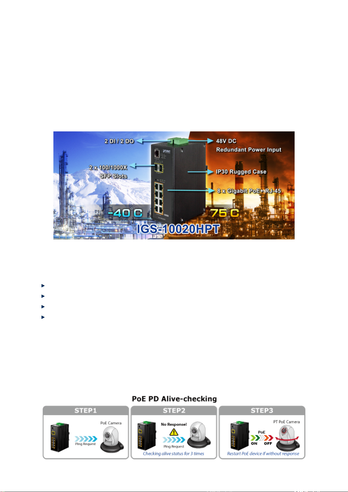
User’s Manual of IGS-10020PT / IGS-10020HPT
25
1.2 Product Description
Environmentally Hardened Design
The Industrial 8-Port Gigabit 802.3af/at PoE Switch, IGS-10020PT/HPT, is equipped with rugged IP30 metal case for stable
operation in heavy Industrial demanding environments. With IP30 industrial case protection, the IGS-10020PT/HPT provides a
high level of immunity against electromagnetic interference and heavy electrical surges which are usually found on plant floors
or in curb side traffic control cabinets. Being able to operate in wide temperature range from -40 to 75 degrees C, the
IGS-10020PT/HPT can be placed in almost any difficult environment. The IGS-10020PT/HPT also allows either DIN rail or wall
mounting for efficient use of cabinet sp ace .
Built-in Unique PoE Functions for Powered Devices Management
As a managed PoE Switch for surveillance, wireless and VoIP network, the IGS-10020PT/HPT features three special PoE
Management functions:
PD ALIVE Check
Schedule Power Recycle
SMTP/SNMP Trap Event Alert
PoE Schedule
Intelligent Alive Check for Powered Device
The IGS-10020PT/HPT can be configured to monitor connected PD (Powered Device) status in real-time via ping action. Once
the PD stops working and responding, the IGS-10020PT/HPT will resume the PoE port power and bring the PD back to work. It
will greatly enhance the network reliability through the PoE port resetting the PD’s power source and reducing administrator
management burden.
Page 26
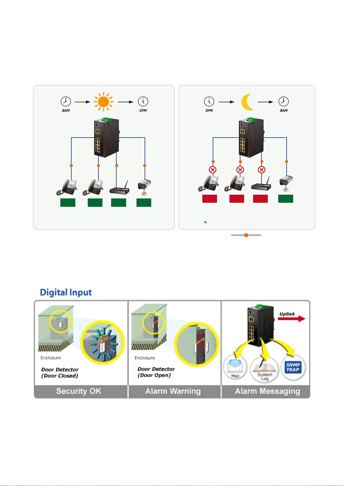
User’s Manual of IGS-10020PT / IGS-10020HPT
26
PoE Schedule for Energy Saving
Under the trend of energy saving worldwide and contributing to environmental protection, the IGS-10020PT/HPT can effectively
control the power supply besides its capability of giving high watts power. The built-in “PoE schedule” function helps you to
enable or disable PoE power feeding for each PoE port during specified time intervals and it is a powerful function to help SMB
or Enterprise save power and money.
PoE
Power
On
6 Watts 6 Watts 12 Watts 12 Watts
Total consumption of 36watts / hr
Digital Input and Digit
5PM8AM
PoE PoE
Power
On
Power
On
Power
On
al Output for external Alarm
PoE
5PM 8AM
PoE
Power
Off
6 Watts 6 Watts 12 Watts 12 Watts
PoE PoE
Power
Off
Power
Off
PoE
Power
On
Saves 24watts / hr during off-business hours
Total Saved = 10800watts / month
PoE
1000Base-T UTP with PoE
The IGS-10020PT/HPT supports Digital Input, and Digital Output on its front panel. This external alarm enables users to use
Digital Input to detect, log external device status (such as door intrusion detector), and send event alarm to the administrators.
The Digital Output could be used to alarm the administrators if the IGS-10020PT/HPT port is link-down, link-up or power-failed.
Page 27
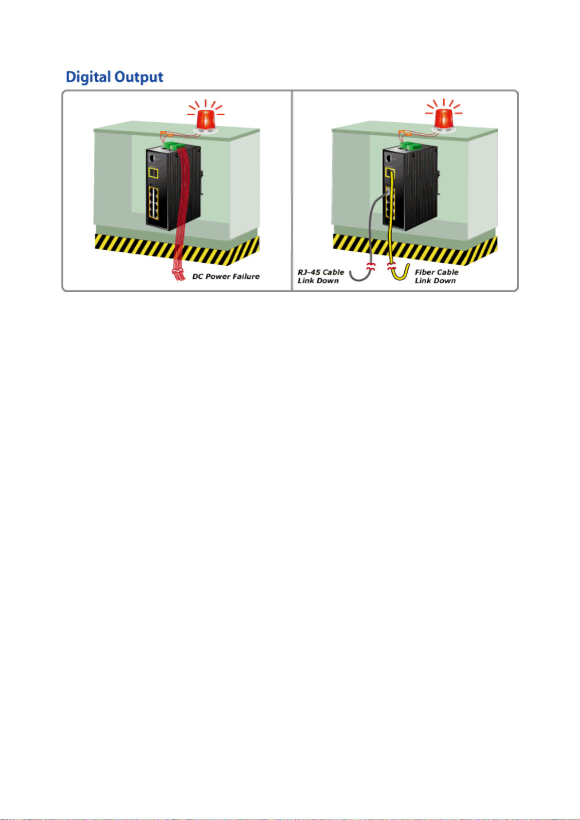
User’s Manual of IGS-10020PT / IGS-10020HPT
27
Robust Layer 2 Feafures
The IGS-10020PT/HPT can be programmed for advanced switch management function, such as dynamic port link aggregation,
Q-in-Q VLAN, private VLAN, rapid spanning tree protocol, layer2 to layer4 QoS, bandwidth control and IGMP/MLD snooping.
The IGS-10020PT provides 802.1Q tagged VLAN and the VLAN groups allowed will be maximally up to 255. The
IGS-10020PT/HPT not only allows the operation of a high-sp eed trunk co mbi nin g multi ple p orts, but also supports connect ion
fail-over.
Efficient Management
For efficient management, the IGS-10020PT/HPT managed switch is equipped with console, web and SNMP management
interfaces. With the built-in web-based management interface, the IGS-10020PT/HPT offers an easy-to-use, platform
independent management and configuration facility. The IGS-10020PT/HPT supports SNMP and it can be managed via any
based on standard of SNMP v1 and v2 management software. For text-based management mode, the IGS-10020PT/HPT can
be accessed via Telnet and the console port. Moreover, the IGS-10020PT/HPY offers remote secure management by
supporting SSH, SSL and SNMPv3 connection which can be encrypted the packet content at each session.
Powerful Security
The IGS-10020PT/HPT offers comprehensive layer2 to layer4 access control list (ACL) for enforcing security to the edge. It can
be used to restrict to networ k access by denyi ng pa cket s bas ed on sourc e and dest ination I P addre ss, TCP/ UDP port nu mber or
defined typical network applications. Its protection mechanism also comprises 802.1x Port-based and MAC-based user and
device authentication. With the private VLAN function, communication between edge ports can be prevented to ensure user
privacy. The IGS-10020PT/HPT also provides DHCP Snooping, IP Source Guard and Dynamic ARP Inspection functions to
prevent IP snooping from attack and discard ARP packets with invalid MAC address. The network administrator can now
construct highly secured corporate networks with considerably less time and effort than before.
Flexibility and Extension Solution
The two mini-GBIC slots bu ilt in t he IGS-10020PT/HPT supports dual speed that 100Base-FX and 1000Base-SX/LX SFP (Small
Form-factor Pluggable) f iber-o pt ic modules. Now the adm ini s trator can flexibly choos e t he s uit ab le S FP transceiver according to
not only the transmission distance, but also the transmission speed required. The distance can be extended from 550 meters to
2km (Multi-Mode fiber ) up to above 10/20/30/40/50/70/120 kilomet ers ( Sin gle-Mode fiber or WDM fiber). They are well suited for
applications within the enterpri se dat a cent ers and di stributions.
Page 28
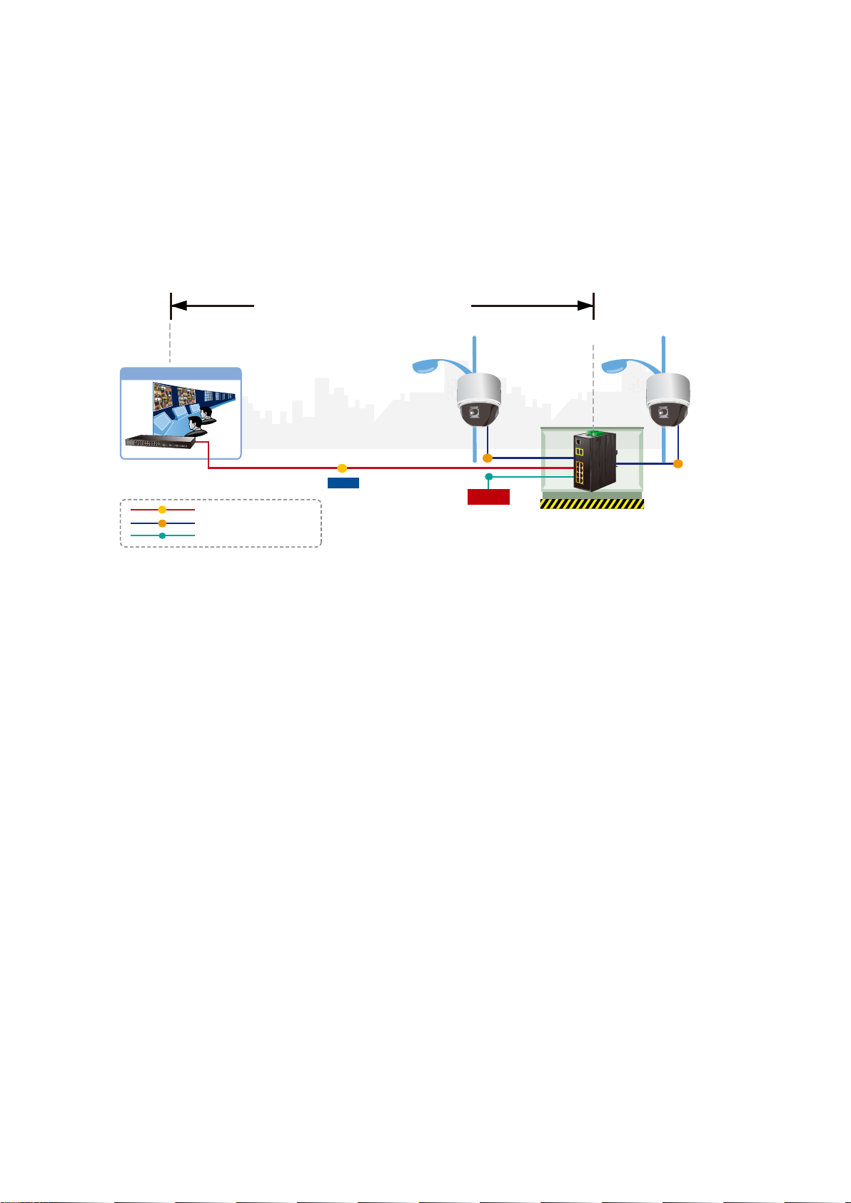
User’s Manual of IGS-10020PT / IGS-10020HPT
28
Perfect Integrafion Solution for Outdoor IP PoE Camera and NVR System
The IGS-10020PT/HPT provides 8 10/100/1000Mbps 802.3af/at PoE ports and can offer sufficient PoE power for 8 PoE IP
cameras at the same time. In addition, with the 2-Port 100/1000Base-X SFP interfaces, the IGS-10020PT/HPT can connect to
core fiber switch and send video stream to NVR and monitor center. Through the high performance switch architecture, the
IGS-10020PT/HPT facilitates the recorded video files from the 8 PoE IP cameras to be saved in the NVR systems.
Furthermore, the NVR systems can be controlled and monitored both in the local LAN and the remote site via Internet. The
IGS-10020PT/HPT undoubtedly brings an ideal, secure surveillance system at a lower total cost.
550m / 10km / 120km
Control Center
PoE+ PTZ
Speed Dome
Fiber Switch
1000
PoE
DC
1000
Data
1000Base-SX/LX Fiber-optic
1000Base-T UTP with PoE
Power Line (DC)
PoE
DC
Power
DC 48V
100m
IGS-10020HPT
1.3 How to Use This Manual
This User Manual is structured as follows:
Section 2, INSTALLATION
The section explains the functions of the Industrial Managed Switch and how to physically install the Industrial
Managed Switch.
Section 3, SWITCH MANAGEMENT
The section contains the information about the software function of the Industrial Managed Switch.
Section 4, WEB CONFIGURATION
PoE
The section explains how to manage the Industrial Managed Switch by Web interface.
Section 5, COMMAND LINE INTERFACE
The section describes how to use the Command Line interface (CLI).
Section 6, CLI MODE
The section explains how to manage the Industrial Managed Switch by Command Line interface.
Section 7, SWITCH OPERATION
The chapter explains how to do the switch operation of the Industrial Managed Switch.
Section 8, TROUBLESHOOTING
The chapter explains how to do troubleshooting of the Industrial Managed Switch.
Appendix A
The section contains cable information of the Industrial Managed Switch.
Appendix B
The section contains Glossary information of the Industrial Managed Switch.
Page 29

User’s Manual of IGS-10020PT / IGS-10020HPT
29
1.4 Product Features
Physical Port
8-Port 10/100/1000Base-T Gigabit Ethernet RJ-45 with IEEE 802.3af / 802.3at PoE Injector
2 100/1000Base-X mini-GBIC/SFP slots, SFP type auto detection
One RJ-45 console interface for basic management and setup
Power over Ethernet
Complies with IEEE 802.3af / IEEE 802.3at Power over Ethernet / End-Span PSE (IGS-10020HPT)
Complies with IEEE 802.3af Power over Ethernet / End-Span PSE (IGS-10020PT)
Up to 8 IEEE 802.3af / 802.3at devices powered (IGS-10020HPT)
Up to 8 IEEE 802.3af devices powered (IGS-10020PT)
Supports PoE Power up to 30.8 watts for each PoE port (IGS-10020HPT)
Supports PoE Power up to 15.4 watts for each PoE port (IGS-10020PT)
Auto detect powered device (PD)
Circuit protection prevents power interference between ports
Remote power feeding up to 100m
PoE Management features:
• IEEE 802.3af and IEEE 802.3at mode switch control (IGS-10020HPT)
• Total PoE power budget control
• Per port PoE function enable/disable
• PoE Admin-mode control
• PoE Port Power feeding priority
• Per PoE port power limit
• PD classifi c ation detection
• Temperat ure T hr e sho ld Contr o l
• PoE Usage Threshold Control
• PD Alive Check
• PoE Schedule
• PD Power Recycling Schedule
Industrial Case / Installation
IP30 aluminum metal case protection
DIN rail and wall mount design
48V DC, redundant power with polarity reverse protect function
Supports EFT protection 6000 VDC for power line
Supports 6000 VDC Ethernet ESD protection
-40 to 75 degrees C operating temperature
Digital Input / Digital Output
2 Digital Input (DI)
2 Digital Output (DO)
Integrate sensors into auto alarm system
Transfer alarm to IP network via email and SNNP trap
Layer 2 Features
Prevents packet loss with back pressure (half-duplex) and IEEE 802.3x PAUSE frame flow control (full-duplex)
Page 30

User’s Manual of IGS-10020PT / IGS-10020HPT
30
High performance of Store-and-Forward architecture and runt/CRC filtering eliminates erroneous packets to optimize
the network bandwidth
Storm Control supp or t:
− Broadcast / Multicast / Unicast
Supports VLAN
− IEEE 802.1Q Tagged VLAN
− Up to 255 VLANs groups, out of 4094 VLAN IDs
− Provider Bridging (VLAN Q-in-Q) support (IEEE 802.1ad)
− Private VLAN Edge (PVE)
− Protocol-based VLAN
− MAC-based VLAN
− Voice VLAN
Supports Spanning Tree Protocol
− STP, IEEE 802.1D Spanning Tree Protocol
− RSTP, IEEE 802.1w Rapid Spanning Tree Protocol
− MSTP, IEEE 802.1s Multiple Spanning Tree Protocol, spanning tree by VLAN
− BPDU Guard
Supports Link Aggregation
− 802.3ad Link Aggregation Control Protocol (LACP)
− Cisco ether-channel (Static Trunk)
− Maximum 5 trunk groups, up to 8 ports per trunk group
− Up to 16Gbps bandwidth( Dupl ex Mode)
Provides Port Mirror (1-to-1)
Port Mirroring to monitor the incoming or outgoing traffic on a particular port
Loop protection to avoid broadcast loops
Supports E.R.P.S. (Ethernet Ring Protection Switching)
Quality of Service
Ingress Shaper and Egress Rate Limit per port bandwidth control
8 priority queues on all switch ports
Traffic classification:
− IEEE 802.1p CoS
− IP TOS / DSCP / IP Precedence
− IP TCP/UDP port number
− Typical network appl ic atio n
Strict priority and Weighted Round Robin (WRR) CoS policies
Supports QoS and In/Out bandwidth control on each port
Traffic-policing policies on the switch port
DSCP remarking
Multicast
Supports IGMP Snooping v1, v2 and v3
Supports MLD Snooping v1 and v2
Page 31

User’s Manual of IGS-10020PT / IGS-10020HPT
31
Querier mode support
IGMP Snooping port filtering
MLD Snooping port filtering
MVR (Multicast VLAN Registration)
Security
IEEE 802.1x Port-based / MAC-based network access authentication
Built-in RADIUS client to co-operate with the RADIUS servers
TACACS+ login users access authentication
RADIUS / TACACS+ users access authentication
IP-based Access Control List (ACL)
MAC-based Access Control List
Source MAC / IP address binding
DHCP Snooping to filter untrusted DHCP messages
Dynamic ARP Inspection discards ARP packets with invalid MAC address to IP address binding
IP Source Guard prev e nt s IP spoofing attacks
Auto DoS rule to defend DoS attack
IP address access management to prevent unauthorized intruder
Management
Switch Management Interfaces
− Console / Telnet Command Line Interface
− Web switch management
− SNMP v1 and v2c switch man agem ent
− SSH / SSL and SNMP v3 secure access
Four RMON groups (history, statistics, alarms, and events)
IPv6 IP Address / NTP / DNS management
Built-in Trivial File Transfer Protocol (TFTP) client
BOOTP and DHCP for IP address assignment
Firmware upload/download via HTTP / TFTP
DHCP Relay
DHCP Option82
User Privilege levels control
NTP (Network Time Protocol)
Link Layer Discovery Protocol (LLDP) Protocol
SFP-DDM (Digital Diagnostic Monit or)
Cable Diagnostic technology provides the mechanism to detect and report potential cabling issues
Reset button for system reboot or reset to factory default
PLANET Smart Discovery Utility for deploy management
Page 32

User’s Manual of IGS-10020PT / IGS-10020HPT
32
Throughput (packet per second)
> 10 sec: Factory Default
2 Digital Output (DO): Open collector to 24VDC, 100mA max.
System:
LNK/ACT (Green)
1.5 Product Specifications
Product IGS-10020PT IGS-10020HPT
Hardware Specificati on
Copper Ports 8 10/ 100/1000Base-T RJ-45 Auto-MDI/MDI-X ports
SFP/mini-GBIC Slots
Console 1 x RJ-45-to-RS-232 serial port (115200, 8, N, 1)
Switch Architecture Store-and-Forward
Switch Fabric 20Gbps / non-blocking
Address Table 8K entries, automatic source address learning and ageing
Share Data Buffer 4Mbits
Flow Control
Jumbo Frame 9Kbytes
Reset Button
ESD Protection 6KV DC
EFT Protection 6KV DC
Enclosure IP30 Aluminum Metal Case
2 1000Base-SX/LX/BX SFP interfaces (Port-9 and Port-10)
Compatible with 100Base-FX SFP
14.8Mpps@ 64Bytes packet
IEEE 802.3x Pause Frame for Full-Duplex
Back pressure for Half-Duplex
< 5 sec: System reboot
Installation DIN Rail Kit and Wall Mount Kit
Removable 6-pin terminal block for power input
Connector
Alarm One relay output for power failure. Alarm Relay current carry ability: 1A @ DC 24V
DI/DO
LED Indicator
Pin 1/2 for Power 1; Pin 3/4 for fault alarm; Pin 5/6 for Power 2
Removable 6-pin terminal block for DI/DO interface
Pin 1/2 for DI 1 & 2; Pin 3/4 for DO 1 & 2; Pin 5/6 for GND
2 Digital Input (DI): Level 0: -24V~2.1V (±0.1V)
Level 1: 2.1V~24V (±0.1V)
Input Load to 24V DC, 10mA max.
Power 1 (Green)
Power 2 (Green)
Fault Alarm (Green)
Ring (Green)
Ring Owner (Green)
Per 10/100/1000T RJ-45 Ports:
PoE In-Use (Orange)
LNK/ACT (Green)
Per SFP Interface:
1000 (Orange)
Page 33

User’s Manual of IGS-10020PT / IGS-10020HPT
33
31.9 watts / 108.78BTU (Full loading
with
PoE function)
31.9 watts / 108.78BTU (Full loading
PoE function)
Ethernet / PSE
PoE Power Supply Type
End-Span
(IEEE 802.3at)
Power Pin Assignment
1/2(+), 3/6(-)
input)
input)
Max. number of Class 2 PD
8
Max. number of Class 3 PD
8
Max. number of Class 4 PD
-
8
Dimensions (W x D x H)
Weight 1684g
Power Requirements DC 48V
Power Consumption
Power Over Ethernet
PoE Standard IEEE 802.3af Power over Ethernet / PSE
PoE Power Output
PoE Power Budget
152 x 107x 72mm
without PoE function)
161.9 watts / 522.08BTU (Full loading
Per Port 48V DC, 350mA . Max. 15.4
watts
130W maximum (depending on power
without PoE function)
306 watts / 1043.46BTU (Full loading with
IEEE 802.3af / IEEE 802.3at Power over
Per Port 56V DC, 350mA . Max. 15.4
watts (IEEE 802.3af)
Per Port 56V DC, 590mA. Max. 30 watts
270W maximum (depending on power
Layer 2 Function
Basic Management Interfaces Console, Telnet, Web Browser, SNMPv1, v2c
Secure Management Interfaces SSH, SSL, SNMP v3
Port disable/enable
Port Configuration
Port Status
Port Mirroring
VLAN
Auto-Negotiation 10/100/1000Mbps full and half duplex mode selection
Flow Control disable / enable
Power saving mode control
Display each port’s speed duplex mode, link status, Flow control status. Auto
negotiation status, trunk status.
TX / RX / Both
1 to 1 monitor
802.1Q Tagged Based VLAN, up to 255 VLAN groups
Q-in-Q tunneling
Private VLAN Edge (PVE)
MAC-based VLAN
Protocol-based VLAN
Link Aggregation
Voice VLAN
MVR (Multicast VLAN Registration)
Up to 255 VLAN groups, out of 4094 VLAN IDs
IEEE 802.3ad LACP / Static Trunk
Supports 5 groups of 8-Port tr unk suppor t
Page 34

34
- DSCP/TOS field in IP Packet
Egress: 500Kb~1000Mbps
MAU-MIB
IEC60068-2-6 (Vibration)
IEEE 802.1ab LLDP
QoS
User’s Manual of IGS-10020PT / IGS-10020HPT
Traffic classification based, Strict priority and WRR
8-Level priority for switching
- Port Number
- 802.1p priority
- 802.1Q VLAN tag
IGMP Snooping
MLD Snooping
Access Control List
Bandwidth Control
SNMP MIBs
IGMP (v1/v2/V3) Snooping, up to 255 multicast Groups
IGMP Querier mode support
MLD (v1/v2) Snooping, up to 255 multicast Groups
MLD Querier mode support
IP-based ACL / MAC-based ACL
Up to 123 entries
Per port bandwidth control
Ingress: 500Kb~1000Mbps
RFC-1213 MIB-II
IF-MIB
RFC-1493 Bridge MIB
RFC-1643 Ethernet MIB
RFC-2863 Interface MIB
RFC-2665 Ether-Like MIB
RFC-2819 RMON MIB (Group 1, 2, 3 and 9)
RFC-2737 Entity MIB
RFC-2618 RADIUS Client MIB
RFC-2933 IGMP-STD-MIB
RFC3411 SNMP-Frameworks-MIB
IEEE 802.1X PAE
LLDP
Standards Conformance
Regulation Compliance
Stability Testing
Standards Compliance
FCC Part 15 Class A, CE
IEC60068-2-32 (Free fall)
IEC60068-2-27 (Shock)
IEEE 802.3 10Base-T
IEEE 802.3u 100Base-TX/100Base-FX
IEEE 802.3z Gigabit SX/LX
IEEE 802.3ab Gigabit 1000T
IEEE 802.3x Flow Control and Back pressure
IEEE 802.3ad Port trunk with LACP
IEEE 802.1D Sp ann ing t ree pr ot oc ol
IEEE 802.1w Rapid spanning tree protocol
IEEE 802.1s Multiple spanning tree protocol
IEEE 802.1p Class of service
IEEE 802.1Q VLAN Tagging
IEEE 802.1x Port Authentication Network Control
Page 35

35
RFC 2236 IGMP version 2
Environment
User’s Manual of IGS-10020PT / IGS-10020HPT
IEEE 802.3af Power over Ethernet
IEEE 802.3at Power over Ethernet (IGS-10020HPT)
RFC 768 UDP
RFC 793 TFTP
RFC 791 IP
RFC 792 ICMP
RFC 2068 HTTP
RFC 1112 IGMP version 1
Operating Temperature
Storage Temperature
Humidity
-40 ~ 75 degrees C
-40 ~ 85 degrees C
5 ~ 95% (Non-condensing)
Page 36

User’s Manual of IGS-10020PT / IGS-10020HPT
36
2. INSTALLATION
2.1 Hardware Descriptions
The Managed Switch provides three different running speeds – 10Mbps, 100Mbps and 1000Mbps – in the same Switch and
automatically distinguishes the speed of incoming connection. This section describes the hardware features of the Managed
Switch. For easier management and control of the Managed Switch, familiarize yourself with its display indicators, and ports.
Front panel illustrations in this chapter display the unit’s LED indicators. Before connecting any network device to the Managed
Switch, read this chapter carefully.
2.1.1 Physical Dimensions
IGS-10020PT / IGS-10020HPT
Dimensions (W x D x H) : 72 x 107 x 152 mm
Page 37

User’s Manual of IGS-10020PT / IGS-10020HPT
37
2.1.2 Front Panel
Figure 2-1 & 2-2 shows the front panels of Industrial Managed Switch.
Figure 2-1: IGS-10020PT Switch Front Panel Figure 2-2: IGS-10020HPT Switch Front Panel
Page 38

User’s Manual of IGS-10020PT / IGS-10020HPT
38
Reset Button Pressed and Released
Function
configuration. The Industrial Managed Switch will then reboot
Default Gateway: 192.168.0.254
■ Reset Button
At the left of the front panel, the reset button is designed for rebooting the Industrial Managed Switch without turning off
and on the power. It also can reset the Industrial Managed Switch to factory default mode.
Figure 2-3: Reset button of Industrial Managed Switch
< 5 sec: System Reboot Reboot the Industrial Managed Switch
> 5 sec: Factory Default
2.1.3 LED Indicators
System
LED Color Function
Reset the Industrial Managed Switch to Factory Default
and load the default settings as below:
。 Default Username: admin
。 Default Password: admin
。 Default IP address: 192.168.0.100
。 Subnet mask: 255.255.255.0
。
P1 Green
P2 Green
Fault Green
Lights to indicate that the Switch is powered on by DC1 inpu t.
Lights to indicate that the Switch is powered on by DC2 inpu t.
Lights to indicate that Switch DC or port has failed.
Ring* Green Lights to indicate that the ERPS Ring has been created successfully.
R.O.* Green Lights to indicate that Switch has enabled Ring Owner.
* = features to be expected in the future
Page 39

39
Per 10/100/1000Mbps port with PoE
LED Color Function
User’s Manual of IGS-10020PT / IGS-10020HPT
10/100/1000
Green
LNK/ACT
PoE In-Use Orange
Per SFP Interface (Port-9, Port-10 mini-GBIC)
LED Color Function
LNK / ACT Green
1000 Orange
Lights to indicate the port is running in 10/100/1000Mbps speed and successfully
established.
Blink: indicates that the switch is actively sending or receiving data over that port.
Lights: To indicate the port is providing 48/56V DC in-line power.
Off: To indicate the connected device is not a PoE Powered Device (PD).
Light
Blink Indicates that the Switch is actively sending or receiving data over that port.
Light Indicates that the port is successfully connecting to the network at 1000Mbps.
Off Indicates that the port is successfully connecting to the network at 100Mbps.
Indicates the link through that port is successfully established.
Page 40

User’s Manual of IGS-10020PT / IGS-10020HPT
40
1 2 3 4 5 6 DC 1
DC 2
+ - +
-
2.1.4 Wiring the Power Input
The 6-contact terminal block connector on the top panel of the Industrial Managed Switch is used for two DC redundant power
inputs. Please follow the steps below to insert the power wire.
1. Insert positive / negative DC power wires into the contacts 1 and 2 for DC POWER 1, or 5 and 6 for DC POWER 2.
Figure 2-4: IGS-10020PT / IGS-10020HPT Upper Panel
2. Tighten the wire-clamp screws for preventing the wires from loosening.
Figure 2-5 6-Pin Terminal Block Power Wiring Input
1. The wire gauge for the terminal block should be in the range of 12 ~ 24 AWG.
2. When performing any of the procedures like inserting the wires or tighten the wire-clamp screws,
make sure the power is OFF to prevent from getting an electric sho ck.
Page 41

User’s Manual of IGS-10020PT / IGS-10020HPT
41
2.1.5 Wiring the Fault Alarm Contact
The fault alarm contacts are in the middle (3 & 4) of the terminal block con nector as the p ictu re shows bel ow. Inserting the wires,
the Industrial Managed Switch w ill d etect the fault stat us of the power failure, or port link failur e ( av ai lable for managed model) .
The following illustration shows an application example for wiring the fault alarm contacts
Insert the wires into the fault alarm contacts
1. The wire gauge for the terminal block should be in the range of 12 ~ 24 AWG.
2. When performing any of the procedures like inserting the wires or tighten the wire-clamp screws, make
sure the power is OFF to prevent from getting an electric shock.
Page 42

User’s Manual of IGS-10020PT / IGS-10020HPT
42
1 2 3 4 5
6
2.1.6 Wiring the Digital Input / Output
The 6-contact terminal block connector on the rear panel of IGS-10020PT / IGS-10020HPT is used for Digital Input and Digital
Output. Please follow the steps below to insert wire.
1. The IGS-10020PT / IGS-10020HPT offers two DI and DO groups. 1 and 2 are DI groups, 3 and 4 are DO groups and 5
and 6 are GND (ground).
Figure 2-6 Wiring the Redundant Power Inputs
2. Tighten the wire-clamp screws for preventing the wires from loosening.
DI0 DI1 DO0 DO1 GND GND
Figure 2-7 6-Pin Terminal Block DI / DO Wiring Input
3. There are two Digital Input groups for you to monitor two different devices. The following topology shows how to wire DI0
and DI1.
Page 43

User’s Manual of IGS-10020PT / IGS-10020HPT
43
Figure 2-8 Wires DI0 and DI1 to Open Detector
4. There are t wo D igita l Outp ut gr oups for you t o sens e IGS-10020PT / IGS-10020HPT port failure or power failure and issue
a high or low signal to external device.The following topology shows how to wire DO0 and DO1.
Figure 2-9 Wires DO0 and DO1 to Open Detector
Page 44

User’s Manual of IGS-10020PT / IGS-10020HPT
44
2.2 Install the Industrial Managed Switch
This section describes how to install the Industrial Managed Switch and make connections to it. Please read the following
topics and perform the procedures in the order being presented. To install your Industrial Managed Switch on a desktop or
shelf, simply complete the following steps.
In this paragraph, we will describe how to install the Industrial Managed Switch and the installation points attended to it.
2.2.1 Installation Steps
1. Unpack the Industrial Managed Switch
2. Check if the DIN-Rail is screwed on the Industrial Managed Switch or not. If the DIN-Rail is not screwed on the
Industrial Managed Switch, please refer to DIN-Rail Mounting section for DIN-Rail installation. If users want to
wall-mount the Industrial Managed Switch, please refer to the Wall Mount Plate Mounting section for wall-mount plate
installation.
3. To hang the Industrial Managed Switch on the DIN-Rail track or wall.
4. Power on the Industrial Managed Switch. Please refer to the Wiring the Power Inputs section for knowing the
information about how to wire the power. The power LED on the Industrial Managed Switch will light up. Please refer to
the LED Indicators section for indication of LED lights.
5. Prepare the twisted-pair, straight through Category 5 cable for Ethernet connection.
6. Insert one side of RJ-45 cable (category 5) into the Industrial Managed Switch Ethernet port (RJ-45 port) and anothe r
side of RJ-45 cable (category 5) to the network device’s Ethernet port (RJ-45 port), ex: Switch PC or Server. The UTP port
(RJ-45) LED on the Industrial Managed Switch will light up when the cable is connected with the network device. Please
refer to the LED Indicators section for LED light indication.
Make sure that the connected network devices support MDI/MDI-X if it does not support, or
use the crossover category-5 cable.
7. When all connections are set and LED lights all show normal, the installation is completed.
Page 45

User’s Manual of IGS-10020PT / IGS-10020HPT
45
2.2.2 DIN-Rail Mounting
This section describes how to install the Industrial Managed Switch.
There are two methods to install the Industrial Managed Switch -- DIN-Rail Mounting and Wall Mount Plate Mounting. Please
read the following topics and perform the procedures in the order being presented.
In the installation steps below, this Manual uses IGS-801 (PLANET 8 Port Industrial Gigabit Switch) as the
example. However, the steps for PLANET Industrial Gigabit PoE+ Switch are similar.
Step 1: Screw the DIN-Rail on the Industrial Managed Switch.
Step 2: Lightly insert the bottom of the switch into the track.
Page 46

User’s Manual of IGS-10020PT / IGS-10020HPT
46
Step 3: Check if the DIN-Rail is tightly on the track.
Please refer to following procedures to remove the Industrial Managed Switch from the track.
Step 1: Lightly pull ou t the bottom of the switch for removing it from the track.
Page 47

User’s Manual of IGS-10020PT / IGS-10020HPT
47
2.2.3 Wall Mount Plate Mounting
To install the Industrial Managed Switch on the wall, please follow the instructions below.
In the installation steps below, this Manual uses IGS-801 (PLANET 8 Port Industrial Gigabit Switch)
as the example. However, the steps for PLANET Industrial Gigabit PoE+ Switch are similar.
Step 1: To remove the Industrial Manage d S witch from the DIN-Rail, use the screwdriver t o loosen the screws and re mov e the
DIN-Rail.
Step 2: Place the wall mount plate on the rear panel of the Industrial Managed Switch.
Step 3: Use the screws to screw the wall mount plate on the Industrial Managed Switch.
Step 4: Use the hook holes at the corners of the wall mount plate to hang the Industrial Managed Switch on the wall.
Step 5: To remove the wall mount plate, reverse steps above.
Page 48

User’s Manual of IGS-10020PT / IGS-10020HPT
48
Port Type
Cable Type
Connector
10Base-T
Cat 3, 4, 5, 2-pair
RJ-45
100Base-TX
Cat.5 UTP, 2-pair
RJ-45
1000Base-T
Cat.5/5e/6 UTP, 2-pair
RJ-45
100Base-FX
50 / 125µm or 62.5 / 125µm multi-mode 9 / 125µm single-mode
LC (Multi / Single mode)
1000Base-SX/LX
50 / 125µm or 62.5 / 125µm multi-mode 9 / 125µm single-mode
LC (Multi / Single mode)
2.3 Cabling
10/100/1000Base-T and 100Base-FX / 1000Base-SX/LX
All 10/100/1000Base-T ports come wit h Auto-Negotiation capability. They automatically support 1000Base-T, 100Base-TX
and 10Base-T networks. Users only need to plug a working network device into one of the 10/100/1000Base-T ports, and
then turn on the Industrial Managed Switch. The port will automatically run in 10Mbps, 20Mbps, 100Mbps or 200Mbps
and 1000Mbps or 2000Mbps after the negotiation with the connected device.
The Industrial Managed Switch has eight SFP interfaces that support 100/1000Mbps dual speed mode (optional
multi-mode/ single-mode 100Base-FX/1000Base-SX/LX SFP module)
Cabling
Each 10/100/1000Base-T port uses RJ-45 sockets -- similar to ph one jacks -- for connection of unshielded twisted-pair
cable (UTP). The IEEE 802.3/802.3u 802.3ab Fast/Gigabit Ethernet standard requires Category 5 UTP for 100Mbps
100Base-TX. 10Base-T networks can use Cat.3, 4, 5 or 1000Base-T use 5/5e/6 UTP (see table below). Maximum dis tance
is 100meters (328 feet). The 100Base-FX/1000Base-SX/LX SFP slot is used as LC connector with optional SFP module.
Please see table below and know more about the cable specifications.
Any Ethernet devices like hubs/PCs can connect to the Industrial Managed Switch by using straight-through wires. The
two 10/100/1000Mbps ports are auto-MDI/MDI-X , which can be used on straight-through or crossover cable.
Page 49

User’s Manual of IGS-10020PT / IGS-10020HPT
49
2.3.1 Installing the SFP Transceiver
The sections describe how to insert an SFP transceiver into an SFP slot. The SFP transceivers are hot-pluggable and
hot-swappable. You can plug-in and out the transceiver to/from any SFP port without having to power down the Industrial
Managed Switch as the Figure 2-9 appears.
Figure 2-9: Plugging in the SFP Transceiver
Approved PLANET SFP Transceivers
PLANET Industrial Managed Switch supports 100/1000 dual mode with both Single mode and Multi-mode SFP
transceiver. The following list of approved PLANET SFP transceivers is correct at the time of publication:
Gigabit SFP Transceiver Modules
MGB-GT SFP-Port 1000Base-T Module
MGB-SX SFP-Port 1000Base-SX mini-GBIC module
MGB-LX SFP-Port 1000Base-LX mini-GBIC module
MGB-L30 SFP-Port 1000Base-LX mini-GBIC module-30km
MGB-L50 SFP-Port 1000Base-LX mini-GBIC module-50km
MGB-L70
MGB-L120
MGB-LA10
SFP-Port 1000Base-LX mini-GBIC module-70km
SFP-Port 1000Base-LX mini-GBIC module-120km
SFP-Port 1000Base-LX (WDM,TX:1310nm) mini-GBIC module-10km
MGB-LB10
MGB-LA20
MGB-LB20
MGB-LA40
MGB-LB40
SFP-Port 1000Base-LX (WDM,TX:1550nm) mini-GBIC module-10km
SFP-Port 1000Base-LX (WDM,TX:1310nm) mini-GBIC module-20km
SFP-Port 1000Base-LX (WDM,TX:1550nm) mini-GBIC module-20km
SFP-Port 1000Base-LX (WDM,TX:1310nm) mini-GBIC module-40km
SFP-Port 1000Base-LX (WDM,TX:1550nm) mini-GBIC module-40km
Page 50

User’s Manual of IGS-10020PT / IGS-10020HPT
50
degrees C
MGB-TSX
MGB-TLX
MGB-TL30
MGB-TL70
SFP-Port 1000Base-SX mini-GBIC module - 550m (-40~75 degrees C)
SFP-Port 1000Base-LX mini-GBIC module - 10km (-40~75 degrees C)
SFP-Port 1000Base-LX mini-GBIC module - 30km (-40~75 degrees C)
SFP-Port 1000Base-LX mini-GBIC module - 70km (-40~75 degrees C)
Fast Ethernet SFP Transceiver Modules
MFB-FX
MFB-F20
MFB-F40
MFB-F60
MFB-FA20
MFB-FB20
MFB-TFX
MFB-TF20
SFP-Port 100Base-F X Transceiver (1310nm)-2km
SFP-Port 100Base-F X Transceiver (1310nm)-20km
SFP-Port 100Base-F X Transceiver (1310nm)-40km
SFP-Port 100Base-F X Transceiver (1310nm)-60km
SFP-Port 100Base-B X Transceiver (WDM,TX:1310nm)-20km
SFP-Port 100Base-B X Tra nsceiver (WDM,TX:1550nm)-20km
SFP-Port 100Base-FX Transceiver (1310nm) -2km (-40~75 degrees C)
SFP-Port 100Base-FX Transceiver (1310nm) - 20km (-40~75 degrees C)
1. It is recommended to use PLANET SFPs on the Industrial Managed Switch . If you ins ert an
SFP transceiver that is not supported, the Industrial Managed Switch will not recognize it.
2. Please choose the SFP transceiver which can be operated under -40~75
temperature if the switch device is working in a 0~50 degrees C temperature environment.
1000Base-SX/LX:
Before connecting the other switches, workstation or media converter.
1. Make sure both sides of the SFP transceiver are with the same media type, for exampl e, 1000Base-SX to 1000Base-SX,
1000Bas-LX to 1000Base-LX.
2. Check the fib er-opt ic cab le typ e that matches the SFP transceiver model.
To connect to 1000Base-SX SFP transceiver, use the multi-mode fiber cable with one side being the male duplex LC
connector type.
To connect to 1000Base-LX SFP transceiver, use the single-mode fiber cable w ith one side being the male duplex LC
connector type.
Connect the fiber cable
1. Attach the duplex LC connector on the network cable into the SFP transceiver.
2. Connect the other end of the cable to a device – switches with SFP installed, fiber NIC on a workstation or a media
converter.
3. Check the LNK/ACT LED of the SFP slot on the front of the Industrial Managed Switch. E nsure that the SFP tr ans ce iv er
is operating correctly.
100Base-FX:
Before connecting the other switches, workstation or media converter.
1. Make sure both sides of the SFP transceiver are with the same media type or WDM pair; for example, 100Base-FX to
100Base-FX, 100Base-BX20-U to 100Base-BX20-D.
2. Check the fiber-opt ic cab le typ e that matches the SFP transceiver model.
Page 51

User’s Manual of IGS-10020PT / IGS-10020HPT
51
to a horizo ntal
position. Directly pulling out the module could damage the module and the SFP module slot of the
To connect to MFB-FX SFP transceiver, use the multi-mode fiber cable with one side being the m ale dup lex LC
connector type.
To connect to MFB-F20/F40/F60/FA20/FB20 SFP transceiver, use the single-mode fiber cable with one side being
the male duplex LC connector type.
Connect the fiber cable
1. Attach the duplex LC connector on the network cable into the SFP transceiver.
2. Connect the other end of the cable to a device – switches with SFP installed, fiber NIC on a workstation or a media
converter.
3. Check the LNK/ACT LED of the SFP slot of the switch/converter. Ensure that the SFP transceiver is operating correctly.
4. Check the Link mode of the SFP port if the link fails. Co works with some fiber-NICs or media converters. Set the Link
mode to “100 Force” when needed.
2.3.2 Remove the Module
1. Make sure ther e i s no netw ork activ ity by chec king w ith t he net work admin istrator, or through the management interfa ce o f
the switch/converter (if available) to disable the port in advance.
2. Remove the Fiber Optic Cable gently.
3. Lift up the lever of the MGB/MFB module and turn it to a horizontal position.
4. Pull out the module gently through the lever.
Figure 2-10: How to Pull Out the SFP Transceiver Module
Never pull out the module without lifting up the lever of the module and turning it
Managed Switch.
Page 52

User’s Manual of IGS-10020PT / IGS-10020HPT
52
3. SWITCH MANAGEMENT
This chapter explains the methods that you can use to configure management access to the Industrial Managed Switch. It
describes the types of management applicati ons and the co m muni cat ion and ma nage men t protocols that deliver data between
your management device ( w or kstation or personal comput er ) and the system. It also cont ains information about port connection
options.
This chapter covers the following topics:
Requirements
Management Access Overview
Remote Telnet Access
Web Management Acce ss
SNMP Access
Standards, Protocols, and Related Reading
3.1 Requirements
Workstations of subscribers running Windows XP/2003, Vista, Windows 7, MAC OS X, Linux, Fedora, Ubuntu or
other platform compatible with TCP/IP protocols.
The Workstation is installed with Ethernet NIC (Network Interface Card)
Ethernet Port connection
• Network cables - Use standard network (UTP) cables with RJ45 connectors.
• The above Workstation is installed with WEB Browser and JAVA runtime environment Plug-in
It is recommended to use Internet Explore 7.0 or above to access Industrial Managed Switch.
Page 53

User’s Manual of IGS-10020PT / IGS-10020HPT
53
3.2 Management Access Overview
The Industrial Managed Switch gives you the flexibility to access and manage it using any or all of the following methods:
Remote T elnet Interfa ce
Web browser Interface
An external SNMP-based network management application
The Remote Telnet and Web browser interface support are embedded in the Industrial Managed Switch software and are
available for immediate use. Each of these management methods has their own advantages. Table 3-1 compares the three
management methods.
Method Advantages Disadvantages
Remote
Telnet
Web Browser
SNMP Agent
• Text-based
• Telnet functionality built into Windows
XP/2003, Vista, Windows 7 operating
systems
• Can be accessed from any location
• Ideal for configuring the switch remotely
• Compatible with all popular browsers
• Can be accessed from any location
• Most visually appealing
• Communicates with switch functions at
the MIB level
• Based on open standards
Table 3-1: Management Methods Comparison
• Security can be compromised (hackers need
only know the IP address)
• Security can be compromised (hackers need
only know the IP address and subnet mask)
• May encounter lag times on poor connections
• Requires SNMP manager software
• Least visually appealing of all three methods
• Some settings require calculations
• Security can be compromised (hackers need
only know the community name)
Page 54

User’s Manual of IGS-10020PT / IGS-10020HPT
54
3.3 CLI Mode Management
There are two ways for CLI mode management, one is remote telnet, and the other is operating from console port. Remote
telnet is an IP-based protocol, and con sole port is for user to operat e the I nd ustr ial M anage d Switch on local only ; h owever their
operation is the same.
The command line user interface is for performing system administration, such as displaying statistics or changing option
settings. Using this m etho d, you can access the Industrial Managed Switch remote telnet interface from personal computer, or
workstation in the same Ethernet environment as long as you know the current IP address of the Industrial Managed Switch.
Figure 3-1: Remote Telnet and Console Port Interface Management
In Windows system, you may click “Start” and then choose “Acessories”and “Command Prompt”. Please input “telnet
192.168.0.100” and press “enter’ from your keyboard. The following screen (see Fig ure 3-2) will appear.
Page 55

User’s Manual of IGS-10020PT / IGS-10020HPT
55
Figure 3-2: Remote Telnet Interface Main Screen of Industrial Managed Switch
For more information about using the Remote Telnet interface, refer to Chapter 5 Remote Telnet Interface Management.
Page 56

User’s Manual of IGS-10020PT / IGS-10020HPT
56
3.4 Web Management
The Industrial Managed Switch offers management f eatures that allow users to man age the Industrial Managed Switch from
anywhere on the network through a standard browser such as Microsoft Internet Explorer. After you set up your IP address for
the Industrial Managed Switch, you can access the Industrial Managed Switch’s Web interface applications directly in your
Web browser by entering the IP address of the Industrial Managed Switch.
Figure 3-3: Web Management
You can then use your Web browser to list and manage the Industrial Managed Switch configuration p ar a meter s fr om one
central location; the Web Management requires Microsoft Internet Explorer 7.0 or later.
Figure 3-4: Web Main Screen of Industrial Managed Switch
Page 57

User’s Manual of IGS-10020PT / IGS-10020HPT
57
3.5 SNMP-Based Network Management
You can use an external SNMP-based application to configure and manage the Industrial Managed Switch, such as SNMP
Network Manager, HP Openview Network Node Management (NNM) or What’s Up Gold. This management method requires
the SNMP agent on the Industrial Managed Switch and the SNMP Network Management Station to use the same community
string. This management method, in fact, uses two community strings: the get community string and the set community
string. If the SNMP Net-work management Station only knows the set community string, it can read and write to the MIBs.
However, if it only knows the get community string, it can only read MIBs. The default getting and setting community strings for
the Industrial Managed Switch are public.
Figure 3-5: SNMP Management
Page 58

User’s Manual of IGS-10020PT / IGS-10020HPT
58
3.6 PLANET Smart Discovery Utility
For easily listing the Industrial Managed Switch in your Ethernet environment, the Planet Smart Discovery Utility from user’s
manual CD-ROM is an ideal solution. The following installation instructions are to guide you to running the Planet Smart
Discovery Utility.
1. Deposit the Planet Smart Discovery Utility in administrator PC.
2. Run this utility and the following screen appears.
Figure 3-6: Planet Smart Discovery Utility Screen
If there are two LAN cards or above in the same administrator PC, choose a different LAN card
by using the “Select Adapter” tool.
3. Press “Refresh” button for the currently connected devices in the discovery list a s the sc reen shows below:
Figure 3-7: Planet Smart Discovery Utility Screen
Page 59

User’s Manual of IGS-10020PT / IGS-10020HPT
59
1. This utility shows all the necessary information from the devices, such as MAC Address, Device Name, firmware version,
and Device IP Subnet address. It can also assign new password, IP Subnet address and description for the devices.
2. After setup is complet ed, press “Update Device”, “Updat e Multi ” or “Up dat e All” button to take effect. The meaning of
the 3 buttons above are shown below:
Update Device: us e curr ent s ettin g on one single devi ce.
Update Multi: use current setting on choose multi-devices.
Update All: use current setting on whole devices in the list.
The same functions mentioned above also can be found in “Option” tools bar.
3. To click the “Control Packet Force Broadcast” function, it can allow assign new setting value to the Web Smart Switch
under a different IP subnet address.
4. Press “Connect to Device” button and the Web login scr ee n appear s in Figure 3-4.
5. Press “Exit” button to shutdown the planet Smart Discovery Utility.
Page 60

User’s Manual of IGS-10020PT / IGS-10020HPT
60
The user has to
4. WEB CONFIGURATION
This section introduces the configuration and functions of the Web-Based management.
About Web-based Management
The Industrial Managed Switch offers management f eatures that allow users to man age the Industrial Managed Switch from
anywhere on the network through a standard browser such as Microsoft Internet Explorer.
The Web-based Management supports Internet Explorer 7.0. It is based on Java Applets with an aim to reduce network
bandwidth consumption, enhance access speed and present an easy viewing screen.
By default, IE7.0 or later version does not allow Java Applets to open sockets.
explicitly modify the browser setting to enable Java Applets to use network ports.
The Industrial Managed Switch can be configured through an Ethernet connection, making sure the manager PC must be set
on the same IP subnet address as the Industrial Managed Switch.
For example, the default IP address of the Industrial Managed Switch is 192.168.0.100, then the manager PC should be set
at 192.168.0.x (where x is a number between 1 and 254, except 100), and the default subnet mask is 255.255.255.0.
If you have changed the default IP address of the Industrial Managed Switch to 192.168.1.1 with subnet mask 255.255.255.0
via console, then the manager PC should be set at 192.168.1.x (where x is a number between 2 and 254) to do the relative
configuration on manager PC.
Figure 4-1-1: Web Management
Page 61

User’s Manual of IGS-10020PT / IGS-10020HPT
61
Logging on the Industrial Managed Switch
1. Use Internet Explorer 7.0 or above Web browser. Enter the factory-default IP address to ac cess the We b interf ace . T he
factory-default IP Address is shown as follows:
http://192.168.0.100
2. When the following login screen appears, please enter the default username "admin" with password “admin” (or the
username/password you have changed via console) to login the main screen of Industrial Managed Switch. The login
screen in Figure 4-1-2 appears.
Figure 4-1-2: Login Screen
Default User name: admin
Default Password: admin
After entering the username and password, the main screen appears as Figure 4-1-3.
Page 62

User’s Manual of IGS-10020PT / IGS-10020HPT
62
Figure 4-1-3: Default Main Page
Now, you can use the Web management interf a ce to contin u e the switch mana ge ment or mana ge t he Industrial Managed
Switch by Web interface. The Switch Menu on the left of the web page lets you access all the commands and statis tics the
Managed Switch provides.
1. It is recommended to use Internet Explore 7.0 or above to access Industrial Managed
Switch.
2. The changed IP address takes effect immediately after clicking on the Save button. You
need to use the new IP address to access the Web interface.
3. For security reason, please change and memorize the new password after this first setup.
4. Only accept command in lowercase letter under web interface.
Page 63

User’s Manual of IGS-10020PT / IGS-10020HPT
63
4.1 Main Web Page
The Industrial Managed Switch provides a Web-based browser inter f ac e for configuring and managing it. This interface allows
you to access the Industrial Managed Switch using the Web browser of your choice. This chapter describes how to use the
Industrial Managed Switch’s Web browser interface to configure and manage it.
Main Functions Menu
Copper Port Link Status
SFP Port Link Status
Panel Display
The web agent displays an image of the Industrial Managed Switch’s ports. The Mode can be set to display different
information for the ports , including Link up or Link down. Clicking on the image of a port opens the Port Statistics page.
The port states are illustrated as follows:
Help Button
Figure 4-1-4: Main Page
State Disabled Link Down Link Up PoE On
RJ-45 Ports
SFP Ports
Not Supported
Main Screen
Page 64

User’s Manual of IGS-10020PT / IGS-10020HPT
64
Main Menu
Using the onboard web agent , you can define system p arameters, manage and contro l th e Industrial Managed S witch , a nd all
its ports, or monitor network conditions. Via the Web-Management, the administrator can set up the Industrial Managed
Switch by selecting the functions those listed in the Main Function. The screen in Figure 4-1-5 appears.
Figure 4-1-5: Industrial Managed Switch Main Functions Menu
Page 65

User’s Manual of IGS-10020PT / IGS-10020HPT
65
4.2 System
Use the System menu items to display and configure basic administrative details of the Industrial Managed Switch. Under the
System the following topics are provided to configure and view the system information.
4.2.1 System Information
The System Info page provides information for the current device information. System Info page helps a switch administra t or to
identify the hardware MAC address, software version and system uptime. The screen in Figure 4-2-1 appears.
The page includes the following fields:
Object Description
• Contact
• Name
• Location
• MAC Address
• Power
• Temperature
• System Date
The system contact co nfigured in Configuration | Sy s tem | Information | System Contact.
The system name configured in Configuration | System | Information | System Name.
The system location configured in Configuration | System | Information | System
Location.
The MAC Address of this Industrial Managed Switch.
The Power 1 and Power 2 ON/OFF Status display.
The Temperature shows current of the switch inside temperature status.
The current (GMT) system time and date. The system time is obtained through the
Figure 4-2-1: System Information Page Screenshot
Page 66

User’s Manual of IGS-10020PT / IGS-10020HPT
66
configured SNTP Server, if any.
• System Uptime
• Software Version
• Software Date
Buttons
Auto-refresh : Check this box to refresh the page automatically. Automatic refresh occurs every 3 seconds.
: Click to refresh the page.
The period of time the device has been operational.
The software version of the Industrial Managed Switch.
The date when the switch software was produced.
4.2.2 IP Configuration
The IP Configura tion includes t he IP Ad dress, S ubnet M ask and Gateway. The Configured column is used to view or change the
IP configuration. Fill out the IP Address, Subnet Mask and Gateway for the device. The screen in Figure 4-2-2 appears.
Figure 4-2-2: IP Configuration Page Screenshot
The Current column is used to show the active IP configuration.
Object Description
• DHCP Client
Enable the DHCP client by checking this box. If DHCP fails and the configured IP
Page 67

User’s Manual of IGS-10020PT / IGS-10020HPT
67
address is zero, DHCP will retry. If DHCP server does not respond around 35 seconds
and the configured IP address is non-zero, DHCP will stop and the configured IP
settings will be used. The DHCP client will announce the configured System Name as
host name to provide DNS lookup.
Buttons
• IP Address
• IP Mask
• IP Router
• VLAN ID
• DNS Server
• DNS Proxy
: Click to save changes.
: Click to undo any changes made locally and revert to previously saved values.
: Click to renew DHCP Client. This button is only available if DHCP Client is enabled.
Provide the IP address of this switch in dotted decimal notation.
Provide the IP mask of this switch dotted deci mal notation.
Provide the IP address of the router in dotted decimal notation.
Provide the managed VLAN ID. The allowed range is 1 through 4095.
Provide the IP address of the DNS Server in dotted decimal notation.
When DNS proxy is enabled, DUT will relay DNS requests to the current configured
DNS server on DUT, and reply as a DNS resolver to the client device on the network.
4.2.3 IPv6 Configuration
Configure the switch-managed IPv6 information on this page.
The Configured column is used to view or change the IPv6 configuration. The Current column is used to show the active IPv6
configuration. The screen in Figure 4-2-3 appears.
Figure 4-2-3: IPv6 Configuration Page Screenshot
Page 68

68
The page includes the following fields:
Object Description
User’s Manual of IGS-10020PT / IGS-10020HPT
• Auto Configuration
• Address
• Prefix
• Router
Enable IPv6 auto-configuration by checking this box. If system cannot obtain the
stateless address in time, the configured IPv6 settings will be used. The router
may delay responding to a router solicitation for a few seconds. The total time
needed to complete auto-configurati on can be sign ifi can tly longer.
Provide the IPv6 address of this switch. IPv6 address is in 128-bit records
represented as eight fields of up to four hexadecimal digits with a colon
separating each field (:). For example, 'fe80::215:c5ff:fe03:4dc7'. The symbol '::'
is a special syntax that can be used as a shorthand way of representing multiple
16-bit groups of contiguous zeros; but it can appear only once. It can also
represent a legally valid IPv4 address. For example, '::192.1.2.34'.
Provide the IPv6 Prefix of this switch. The allowed range is 1 to 128.
Provide the IPv6 gateway address of this switch. IPv6 address is in 128-bit
records represented as eight fields of up to four hexadecimal digits with a colon
separating each field (:). For example, 'fe80::215:c5ff:fe03:4dc7'. The symbol '::'
is a special syntax that can be used as a shorthand way of representing multiple
16-bit groups of contiguous zeros; but it can appear only once. It can also
represent a legally valid IPv4 address. . For example, '::192.1.2.34'.
Buttons
: Click to save changes.
: Click to undo any changes made locally and revert to previously saved values.
: Click to renew IPv6 Auto Configuration. This button is only available if IPv6 Auto Configuration is enabled.
4.2.4 Users Configuration
This page provides an overview of the current users. Currently the only way to login as another user on the web server is to
close and reopen the browser. After setup is completed, please press “Save” button to take effect. Please login web interface
with new user name and password, the screen in Figure 4-2-4 appears.
Page 69

69
The page includes the following fields:
Object Description
User’s Manual of IGS-10020PT / IGS-10020HPT
Figure 4-2-4: Users Configuration Page Screenshot
Buttons
• User Name
• Privilege Level
: Click to add a new user.
The name identifies the user.
The privilege level of the user. The allowed range is 1 to 15. If the privilege level
value is 15, it can access all groups, i.e. that is granted the full control of the
device. But others value need to refer to each group privilege level. User's
privilege should be the same or greater than the group privilege level to have the
access to that group. By default setting, almost gr oup privilege level 5 has the
read-only access and privilege level 10 has the read-write access. And the
system maintenance (sof tw are uplo ad, f actory d efault s , etc.) needs user priv ileg e
level 15. Generally, the privilege level 15 can be used for an administrator
account, privilege level 10 for a standard user account and privilege level 5 for a
guest account.
Add / Edit User
This page configures a user – add, edit or delete user.
Figure 4-2-5: Add / Edit User Configuration Page Screenshot
Page 70

70
ator account, privile ge lev el 10 f or a sta ndar d user a ccount and pr ivilege
will
The page includes the following fields:
Object Description
User’s Manual of IGS-10020PT / IGS-10020HPT
Buttons
• User Name
• Password
• Privilege Level
A string identifies the user name whose entry should belong to. The allowed
string length is 1 to 32. The valid user name is a combination of letters, numbers
and underscores.
The password of the user. The allowed string length is 0 to 32.
The privilege level of the user. The allowed range is 1 to 15. If the privilege level
value is 15, it can access all groups, i.e. that is granted the full control of the
device. But others value need to refer to each group privilege level. User's
privilege should be same or greater than the group privilege level to have the
access to that group. By default setting, most groups privilege level 5 has the
read-only access and privilege level 10 has the read-write access. And the
system maintenance (software upload, factory defaults and etc.) need user
privilege level 15. Generally, the privilege level 15 can be used for an
administr
level 5 for a guest account.
: Click to save changes.
: Click to undo any changes made locally and revert to previously saved values.
: Click to undo any changes made locally and return to the Users.
: Delete the current user. This button is not available for new configurations (Add new user)
Figure 4-2-6: User Configuration Page Screenshot
After changing the default password, if you forget the password, please press the “Reset”
button on the front panel of the Industrial Managed Switch over 10 seconds and then release.
The current setting includes VLAN, and will be lost and the Industrial Managed Switch
restore to the default mode.
Page 71

User’s Manual of IGS-10020PT / IGS-10020HPT
71
4.2.5 Privilege Levels
This page provides an overview of the privilege levels. After setup is completed, please press “Save” button to take effect.
Please login web interface with new user name and password, the screen in Figure 4-2-7 appears.
Figure 4-2-7: Privilege Levels Configuration Page Screenshot
Page 72

72
The page includes the following fields:
Object Description
User’s Manual of IGS-10020PT / IGS-10020HPT
• Group Name
• Privilege Level
The name identifies the privilege group. In most cases, a privilege level group
consists of a single module (e.g. LACP, RSTP or QoS), but a few of them
contains more than one. The following description defines these privilege level
groups in details:
System: Contact, Name, Location, Timezone, Log.
Security: Aut hentication, System Access Management, Port (contains
Dot1x port, MAC based and the MAC Address Limit), ACL, HTTPS,
SSH, ARP Inspection and IP source guard.
IP: Everything except 'ping'.
Port: Everything except 'VeriPHY'.
Diagnostics: 'ping' and 'VeriPHY'.
Maintenance: CLI- System Reboot, System Restore Default, System
Password, Configuration Save, Configuration Load and Firmware Load.
Web-Users, Privilege Levels and everything in Maintenance.
Debug: Only present in CLI.
Every group has an authorization Privilege level for the following sub groups:
Buttons
: Click to save changes.
: Click to undo any changes made locally and revert to previously saved values.
4.2.6 NTP Configuration
Configuration read-only
Configuration/execute read-write
Status/statistics read-only
Status/statistics read-write (e.g. for clearing of statistics).
User Privilege should be the same or gre ater than t he auth or iz at ion Priv ilege
level to have the access to that group.
Configuring NTP on this page.
NTP is an acronym for Network Time Protocol, a network protocol for synchronizing the clocks of computer systems. NTP
uses UDP (data grams) as transport layer. You can specify NTP Servers and set GMT Time zone. The NTP Configuration
screen in Figure 4-2-8 appears.
Page 73

73
contiguous zeros; but i t can a ppear only once. I t can a lso r epresen t a lega lly v alid
The page includes the following fields:
Object Description
User’s Manual of IGS-10020PT / IGS-10020HPT
Figure 4-2-8: NTP Configuration Page Screenshot
Buttons
• Mode
• Timezone
• Server #
: Click to save changes.
Indicates the NTP mode operation. Possible modes are:
Enabled: Enable NTP mode operation. When NTP mode operation is
enabled, the agent forwards NTP messages between the clients and the
server when they are not on the same subnet domain.
Disabled: Disable NTP mode operation.
Allows to select the time zone according to current location of switch.
Provides the NTP IPv4 or IPv6 address of this switch. IPv6 address is in 128-bit
records represented as eight fields of up to four hexadecimal digits with a colon
separating each field (:).
For example, 'fe80::215:c5ff:fe03:4dc7'. The symbol '::' is a special syntax that
can be used as a shorthand way of representing multi ple 16-bit groups of
IPv4 address. For example, '::192.1.2.34'.
: Click to undo any changes made locally and revert to previously saved values.
Page 74

User’s Manual of IGS-10020PT / IGS-10020HPT
74
4.2.7 Daylight Saving
The Reboot page enables the device to be rebooted from a remote location. Once the Reboot button is pressed, user will
re-access the WEB interface about 60 seconds later. The System Reboot screen in Figure 4-2-9 appears.
The page includes the following fields:
Object Description
• Time Zone
• Acronym
• Daylight Saving Time
Figure 4-2-9: System Reboot Page Screenshot
Allows to select the time zone according to current location of switch.
User can set the acronym of the time zone. This is a User configurable
acronym to identify the time zone. ( Range : Up to 16 alpha-numeric
characters and can contain '-', '_' or '.')
It is used to set the clock forward or backward according to the
configurations set below for a defined Daylight Saving Time duration.
Select 'Disable' to disable the Daylight Saving Time configuration. Select
'Recurring' and configure the Daylight Saving Time duration to repeat the
configuration every year. Select 'Non-Recurring' and configure the
Page 75

User’s Manual of IGS-10020PT / IGS-10020HPT
75
Daylight Saving Time duration for single time configuration. ( Default :
Daylight Saving Time –
Object Description
• Week (Start Time Setting)
• Day (Start Time Setting)
• Month (Start Time Setting)
• Hours (Start Time Setting)
• Minutes (Start Time Setting)
• Week (End Time Setting)
• Day (End Time Setting)
• Month (End Time Setting)
• Hours (End Time Setting)
• Month (End Time Setting)
• Offset
Disabled )
Recurring Mode
Select the starting week number.
Select the starting day.
Select the starting month.
Select the starting hour.
Select the starting minute.
Select the ending week number.
Select the ending day.
Select the ending month.
Select the ending hour.
Select the ending minute.
Enter the number of minutes to add during Daylight Saving Time.
( Range: 1 to 1440 )
Daylight Saving Time – Non-
Object Description
• Month (Start Time Setting)
• Date (Start Time Setting)
• Year (Start Time Setting)
• Hours (Start Time Setting)
• Minutes (Start Time Setting)
• Month (End Time Setting)
• Date (End Time Setting)
• Year (End Time Setting)
• Hours (End Time Setting)
• Minutes (End Time Setting)
• Offset
Recurring Mode
Select the starting month.
Select the starting date.
Select the starting year.
Select the starting hour.
Select the starting minute.
Select the ending month.
Select the ending date.
Select the ending year.
Select the ending hour.
Select the ending minute.
• Enter the number of minutes to add during Daylight Saving Time.
( Range: 1 to 1440 )
Buttons
: Click to save changes.
: Click to undo any changes made locally and revert to previously saved values.
Page 76

User’s Manual of IGS-10020PT / IGS-10020HPT
76
4.2.8 UPnP
Configuring UPnP on this page.
UPnP is an acronym for Universal Plug and Play. The goals of UPnP are to allow devices to connect seamlessly and to
simplify the implementation of networks in the home (data sharing, communications, and entertainment) and in corporate
environments for simplified installation of computer components. The UPnP Co nfiguration screen in Figure 4-2-10 appears.
Figure 4-2-10: UPnP Configuration Page Screenshot
The page includes the following fields:
Object Description
• Mode
• TTL
• Advertising Duration
Indicates the UPnP operation mode . Pos sible mod es are:
Enabled: Enable UPnP mode operation.
Disabled: Disable UPnP mode operation.
When the mode is enabled, two ACEs are added automatically to trap UPNP
related packets to CPU. The ACEs are automatically removed when the mode is
disabled.
The TTL value is used by UPnP to send SSDP advertisement messages. Valid
values are in the range from 1 to 255.
The duration, carried in SSDP packets, is use d to inform a control poi nt or co ntr ol
points about how often it or they should receive an SSDP adver tise ment
message from this switch. If a control point does not receive any message within
the duration, it may sugg est that the switch no longer ex ist s. D ue to the unr eli able
nature of UDP, as standard it is recommended that such refreshment of
advertisements t o b e done at less than one-half of the advertising duration. In the
implementation, the switch sends SSDP messages periodically at the interval
one-half of the advertising duration minus 30 seconds. Valid values are in the
range from 100 to 86400.
Buttons
: Click to save changes.
: Click to undo any changes made locally and revert to previously saved values.
Page 77

User’s Manual of IGS-10020PT / IGS-10020HPT
77
Figure 4-2-11: UPnP Devices shows on Windows My Network Places
4.2.9 DHCP Relay
Configuring DHCP Relay on this page
DHCP Relay is used to forward and to transfer DHCP messages between the clients and the server when they are not on the
same subnet domain.
The DHCP option 82 enables a DHCP relay agent to insert specific information into a DHCP request packets when forwarding
client DHCP packets to a DHCP server and remove the specific inform atio n from a D HC P reply packets w hen for w ar ding s erv er
DHCP packets to a DHCP client. The DHCP server can use this information to implement IP address or other assignment
policies. Specifically the option works by setting two sub-options:
Circuit ID (option 1)
Remote ID (option2).
The Circuit ID sub-option is supposed to include information specific to which circuit the request came in on.
The Remote ID sub-option was designed to carry information relating to the remote host end of the circuit.
The definition of Circuit ID in the switch is 4 bytes in length and the format is "vlan_id" "module_id" "port_no". The parameter of
"vlan_id" is the first two bytes representing the VLAN ID. The parameter of "module_id" is the third byte for the module ID (in
Page 78

User’s Manual of IGS-10020PT / IGS-10020HPT
78
nformation. It w ill enforce the policy. And it only works under
standalone switch it always equals 0; in stackable switch it means swit ch ID). T he p ara meter of "po rt_n o" is th e fourt h byte and it
means the port number.
The Remote ID is 6 bytes in length, and the value is equal to the DHCP relay agent’s MAC address. The DHCP Relay
Configuration screen in Figure 4-2-12 appears.
Figure 4-2-12: DHCP Relay Configuration Page Screenshot
The page includes the following fields:
Object Description
• Relay Mode
• Relay Server
• Relay Information
Mode
Indicates the DHCP relay mode operation. Possible modes are:
Enabled: Enable DHCP relay mode operation. When enable DHCP relay
mode operation, the agent forw ard and t o transfer DHCP messages betw een
the clients and the server when they are not on the same subnet domain.
And the DHCP broadcast message won't flood for security considered.
Disabled: Disable DHCP relay mode operation.
Indicates the DHCP relay server IP address. A DHCP relay agent is used to
forward and to transfer DHCP messages between the clients and the server
when they are not on the same subnet domain.
Indicates the DHCP relay information mode option operation. Possible modes
are:
Enabled: Enable DHCP relay information mode operation. When enable
DHCP relay informa tion mo de oper ation, the age nt in sert sp ecifi c infor mation
(option82) into a DHCP message when forwarding to DHCP server and
remove it from a DHCP message when transferring to DHCP client. It only
works under DHCP relay operation mode enabled.
Disabled: Disable DHCP relay information mode operation.
• Relay Information
Policy
Indicates the DHCP relay information option policy. When enable DHCP relay
information mode operation, if agent receive a DHCP message that already
contains relay agen t i
DHCP relay information operation mode enabled. Possible policies are:
Replace: Replace the original relay information when receive a DHCP
Page 79

79
Keep: Keep the original relay information when receive a DHCP message
Drop: Drop the package when receive a DHCP message that already
Buttons
: Click to save changes.
: Click to undo any changes made locally and revert to previously saved values.
4.2.10 DHCP Relay Statistics
User’s Manual of IGS-10020PT / IGS-10020HPT
message that already contains it.
that already contains it.
contains relay information.
This page provides statistics for DHCP relay. The DHCP Relay Statistics screen in Figure 4-2-13 appears.
Figure 4-2-13: DHCP Relay Statistics Page Screenshot
The page includes the following fields:
Server Statistics
Object Description
• Transmit to Server
• Transmit Error
The number of packets that are relayed from client to server.
The number of packets that resulted in errors while being sent to clients.
• Receive form Server
• Receive Missing Agent
Option
• Receive Missing
Circuit ID
• Receive Missing
Remote ID
The number of packets received from server.
The number of packets received without agent information options.
The number of packets received with the Circuit ID option missing.
The number of packets received with the Remote ID option missing.
Page 80

User’s Manual of IGS-10020PT / IGS-10020HPT
80
• Receive Bad Circuit ID
• Receive Bad Remote
ID
Client Statistics
Object Description
• Transmit to Client
• Transmit Error
• Receive from Client
• Receive Agent Option
• Replace Agent Option
• Keep Agent Optin
• Drop Agent Option
The number of packets whose Circuit ID option did not match known circuit ID.
The number of packets whose Remote ID option did not match known Remote
ID.
The number of relayed packets from server to client.
The number of packets that resulted in error while being sent to servers.
The number of received packets from server.
The number of received packets with relay agent information option.
The number of packets which were replaced with relay agent information opti on.
The number of packets whose relay agent information was retained.
The number of packets that were dropped was received with relay agent
information.
Buttons
Auto-refresh : Check this box to refresh the page automatically. Automatic refresh occurs every 3 seconds.
: Click to refresh the page immediately.
: Clear all statistics.
4.2.11 CPU Load
This page displays the CPU load, using a SVG graph. The load is measured as averaged over the last 100ms, 1sec and 10
seconds intervals. The last 120 samples are graphed, and the last numbers are displayed as text as well.
In order to display the SVG graph, your browser must support the SVG format. Consult the SVG Wiki for more information on
browser support. Specifically, at the time of writing, Microsoft Internet Explorer will need to have a plugin installed to support
SVG. The CPU Load screen in Figure 4-2-14 appears.
Page 81

User’s Manual of IGS-10020PT / IGS-10020HPT
81
n this page, please download Adobe SVG tool and
Figure 4-2-14: CPU Load Page Screenshot
Buttons
Auto-refresh : Check this box to refresh the page automatically. Automatic refresh occurs every 3 seconds.
If your browser cannot display anything o
install it in your computer.
Page 82

User’s Manual of IGS-10020PT / IGS-10020HPT
82
4.2.12 System Log
The switch system log information is provided her e. The System Log screen in Figure 4-2-15 appears.
The page includes the following fields:
Object Description
• ID
• Level
• Time
• Message
Buttons
Figure 4-2-15: System Log Page Screenshot
The ID (>= 1) of the system log entry.
The level of the system log entry. The following level types are supported:
Info: Information level of the system log.
Warning: Warning level of the system log.
Error: Error level of the system log.
All: All levels.
The time of the system log entry.
The message of the system log entry.
Auto-refresh : Check this box to refresh the page automatically. Automatic refresh occurs every 3 seconds.
: Click to update the sy stem log entries, starting from the current entry ID.
: Flushes the selected log entries.
: Hide system log according to entry page. As default System Log Information shows 20 entries for one page. Hide
button can hide the system log entry that has been over one page.
: Click this button to download system log with CSV format file.
Page 83

User’s Manual of IGS-10020PT / IGS-10020HPT
83
: Updates the system log entries, starting from the first available entry ID.
: Updates the system log entries, ending at the last entry currently displayed.
: Updates the system log entries, starting from the last entry currently displayed.
: Updates the system log entries, ending at the last available entry ID.
4.2.13 Detailed Log
The switch system detailed log information is provided here. The Detailed Log screen in Figure 4-2-16 appears.
Figure 4-2-16: Detailed Log Page Screenshot
The page includes the following fields:
Object Description
• ID
• Message
Buttons
: Click this button to download system log with CSV format file.
: Updates the system log entry to the current entry ID.
: Updates the system log entry to the first available entry ID
: Updates the system log entry to the previous available entry ID.
The ID (>= 1) of the system log entry.
The message of the system log entry.
: Updates the system log entry to the next available entry ID.
: Updates the system log entry to the last available entry ID.
: Click this button to print out system log.
Page 84

User’s Manual of IGS-10020PT / IGS-10020HPT
84
4.2.14 Remote Syslog
Configure remote syslog on this page. The Remote Syslog screen in Figure 4-2-17 appears.
Figure 4-2-17: Remote Syslog Page Screenshot
The page includes the following fields:
Object Description
Buttons
• Server Mode
• Server Address
• Syslog Level
Indicates the server mode operation. When the mode operation is enabled, the
syslog message will send out to syslog server. The syslog protocol is based on
UDP communication and r ecei ved on UD P por t 514 and the s yslog server will not
send acknowledgments back s ender sin ce UDP is a connectionless protocol and
it does not provide acknowledgments. The syslog packet will always send out
even if the syslog server does not exist. Possible modes are:
Enabled: Enable server mode operation.
Disabled: Disable server mode operation.
Indicates the IPv4 host address of syslog server. If the switch provide DNS
feature, it also can be a host name.
Indicates what kind of message will send to syslog server. Possible modes are:
Info: Send information, warnings and errors.
Warning: Send warnings and errors.
Error: Send errors.
: Click to save changes.
: Click to undo any changes made locally and revert to previously saved values.
Page 85

85
Object
Description
• SMTP Mode
Enabled
E-mail for alarm noticing
• SMTP Port
authentication.
• Authentic User Name
4.2.15 SMTP Configuration
Configuring SMTP Configuration on this page
The SMTP Configuration screen in Figure 4-2-18 appears.
User’s Manual of IGS-10020PT / IGS-10020HPT
Figure 4-2-18: SMTP Configuration Page Screenshot
The page includes the following fields:
• SMTP Server
• SMTP Authentication Enabled
It is for you to enable SMTP mode function. This mode offers you to configure
SMTP server and SMTP account information, system will refer it to send an
It is for you to set up a specified SMTP server DNS name or IP address. If a
DNS name is inputted, please remember to input DNS server IP address on the
IP configuration page.
It is for you to input the SMTP server port number. The default is "25".
As usual SMTP server is denied to relay a mail from a different domain, so you
have to enable this option and input your mail account and password for SMTP
sever authorizing to forward a mail from a different domain.
For example, you want an SMTP server, which is located on mail.123.com, to
send a mail to mail.456.net.com.
If you want to send the mail to a SMTP server which is located on the same
domain or the same SMTP server, you don't have to enable SMTP
It is for you to input your mail account name.
Page 86

86
• Authentication
Password
• E-mail 1 To
• E-mail 2 To
It is for you to input secondary recipient mail address.
• E-mail From
• E-mail Subject It is for you to input mail subject.
Buttons
: Click to test SMTP server address.
: Click to save changes.
: Click to undo any changes made locally and revert to previously saved values.
User’s Manual of IGS-10020PT / IGS-10020HPT
It is for you to input your mail account password.
It is for you to input who send this mail.
It is for you to input recipient mail address.
4.2.16 Digital Input/Output
Digital Input allows user to log external device (such as industrial cooler) dead or alive or something else. System will log a
user customized message into system log and syslog, and issue SNMP trap or issue an alarm E-mail.
Digital Output allows user to monitor the switch port and power, and let system issue a high or low signal to an external device
(such as alarm) when the monitor port or power has been failed. The Conf ig urati on scre en in Figure 4-2-19 appears.
Page 87

87
The page includes the following fields:
Object Description
User’s Manual of IGS-10020PT / IGS-10020HPT
Figure 4-2-19 Windows File Selection Menu Popup
• Enable
• Condition
• Event Description
• Event
Check the Enable checkbox to enable Digital Input / output function.
Uncheck the Enable checkbox to disable Digital input / output function.
As Digital Input:
Allows user to select High to Low or Low to High. This means a signal rec eiv ed
by system is from High to Low or From Low to High. It will trigger an action that
logs a customize message or issue the message from the switch.
As Digital Output:
Allows user to select High to Low or Low to High. This means
that when the
switch is power-failed or port-failed, then system will issue a High or
Low signal to an external device such as an alarm.
Allows user to set a customized message for Digital Input function alarming.
As Digital Input:
Allows user to record alarm message to System log, syslog or issues out via
SNMP Trap or SMTP.
As default SNMP Trap and SMTP are disabled, please enable them first if you
want to issue alarm message via them.
Buttons
As Digital Output:
Allows user to monitor an alarm from port failure, power failure, Digital Input 0
(DI 0) and Digital Input 1(DI 1) which means if Digital Output has detected
these events, th en Di gitial O utput w ould b e tri ggered a ccordi ng to t he sett ing of
Condition.
• Power Alarm
• Port Alarm
: Click to save changes.
: Click to undo any changes made locally and revert to previously saved values.
Allows user to choose which power module that needs to be monitored.
Allows user to choose which port that needs to be monitored.
Page 88

User’s Manual of IGS-10020PT / IGS-10020HPT
88
4.2.17 Fault Alarm
The Fault Relay Alarm function provides the Power Failure and Port Link Down/Broken detection. With both power input 1 and
power input 2 insta lled and the che ck boxes of power 1/power 2 tic ke d, the FAULT LED indicator will then be pos sib le to light up
when any one of the power failures occurs. As for the Port Link Down/Broken detection, the FAULT LED indicator will light up
when the port failure occurs; certainly the check box beside the port must be ticked first. Please refer to the segment of ‘Wiring
the Fault Alarm Contact’ for the failure detection. The Configuration screen in Figure 4-2-20 appears.
The page includes the following fields:
Object Description
• Enable
• Record
• Action
• Power Alarm
• Port Alarm
Figure 4-2-20 Windows File Selection Menu Popup
Allows user to enable Fault Alarm function.
Allows user to record alarm message to System log, syslog or issues out via
SNMP Trap or SMTP.
As default SNMP Trap and SMTP are disabled, please enable them first if you
want to issue alarm message via them.
Allows user to monitor and alarm from port failure or power failure.
Allows user to choose which power module that needs to be monitored.
Allows user to choose which port that needs to be monitored.
Buttons
: Click to save changes.
: Click to undo any changes made locally and revert to previously saved values.
Page 89

User’s Manual of IGS-10020PT / IGS-10020HPT
89
4.2.18 EEE Power Reduction
This page allows the user to configure the current EEE port settings.
EEE is a power saving option that reduces the power usage when there is low or no traffic utilization.
EEE works by powering down circuits when there is no traffic. When a port gets data to be transmitted, all circuits are powered
up. The time it takes to power up the circuits is named wakeup time. The default wakeup time is 17 us for 1Gbit links and 30 us
for other link speeds. EEE devices must agree upon the value of the wakeup time in order to make sure that both the receiving
and transmitting device has all circuits powered up when traffic is transmitted. The devices can exchange wakeup time
information using the LLDP protocol.
For maximizing power savings, the circuit isn't started at once transmit data is ready for a port, but is instead queued until 3000
bytes of data is ready to be transmitted. For not introducing a large delay in case that data less then 3000 bytes shall be
transmitted, data are always transmitted after 48 us, giving a maximum latency of 48 us + the wakeup time.
If desired it is possible to minimize the latency for specific frames, by mapping the frames to a specific queue (done with QOS),
and then mark the queue a s an ur gent q ueue. When an urgent queue g ets dat a to be tr ansmitte d, the c irc uits w ill be pow ered u p
at once and the latency will be reduced to the wakeup time.
EEE works for ports in auto-negotiation mode, where the port is negotiated to either 1G or 100Mbps full duplex mode.
The EEE Power Reduction screen in Figure 4-2-21 appears.
Figure 4-2-21: EEE Configuration Page Screenshot
Page 90

90
*
The page includes the following fields:
Object Description
User’s Manual of IGS-10020PT / IGS-10020HPT
• Port
• EEE Enable
• EEE Urgent Queues
Buttons
: Click to save changes.
: Click to undo any changes made locally and revert to previously saved values.
The switch port number of the logical EEE
Industrial Managed Switch.
Controls whether or not EEE is enabled for this switch port.
Queues set will activate transmission of frames as soon as any data is available.
Otherwise, the queue will postpone the transmsion until 3000 bytes, which are
ready to be transmitted.
4.2.19 Web Firmware Upgrade
port,
means to select all ports of
This page facilit ates an u pdate on the firmware cont rolling t he Industrial Managed Switch. The Web Firmware Upgrade s creen
in Figure 4-2-22 appears.
Figure 4-2-22: Web Firmware Upgrade Page Screenshot
To open Firmware Upgrade screen, perform the following:
1. Click System -> Web Firmware Upgrade.
2. The Firmware Upgrade screen is displayed as in Figure 4-2-22.
3. Click the “
4. Select on the firmware and then click “
“button of the main page, the system would pop up the file selection menu to choose firmware.
”; the Software Upload Progress would show the file upload status.
5. Once the software is loaded to the syste m succes sfu lly , the following screen appears. The system will load the new
software after reboot.
Page 91

User’s Manual of IGS-10020PT / IGS-10020HPT
91
the update progress i s complete .
Figure 4-2-23: Software Successfully Loaded Notice Screen
DO NOT Power OFF the Industrial Managed Switch until
Do not quit the Firmware Upgrade page without pressing the “OK” button after the image is
loaded. Or the system won’t apply for the new firmware. User has to repeat the firmware
upgrade processes again.
4.2.20 TFTP Firmware Upgrade
The Firmware Upgrade page provides the functions to allow a user to update the Industrial Managed Switch firmware from
the TFTP server in the network . Befor e up dating, make sure you have your TFTP serv er ready and the firmwar e ima ge is o n the
TFTP server. The TFTP Firmware Upgrade screen in Figure 4-2-24 appears.
Figure 4-2-24: TFTP Firmware Update Page Screenshot
The page includes the following fields:
Object Description
• TFTP Server IP
• Firmware File Name
Fill in your TFTP server IP address.
The name of firmware image.
(Maximum length : 24 characters)
Page 92

User’s Manual of IGS-10020PT / IGS-10020HPT
92
<?xml version="1.0"?> and <configuration>. These tags are mandatory and must be present
Buttons
: Click to upgrade firmware.
DO NOT Power OFF the Industrial Managed Switch until the update progress i s complete .
Do not quit the Firmware Upgrade page without pressing the “OK” button after the image is
loaded. Or the system won’t apply for the new firmware. User has to repeat the firmware
upgrade processes again.
4.2.21 Configuration Backup
This function allows backup and reload the current configuration of the Industrial Managed Switch to the local management
station. The Configuration Backup screen in Figure 4-2-25 appears.
Figure 4-2-25: Configuration Save Page Screenshot
Save configuration except IP Address feature is almost the same as Save configuration, except the IP address, which will
not be saved.
You can save/view or load the switch configuration. The configuration file is in XML format with a hierarchy of tags:
Header tags:
at the beginning of the file.
Section tags: <platform>, <global> and <switch>. The platform section must be the first section t ag and
this section must include the correct platform ID and version. The global section is optional
and includes configuration which is not related to specific switch ports. The switch section is
optional and includes configuration which is related to specifi c swi tch p or ts.
Module tags: <ip>, <mac>, <port> etc. These tags identify a module controlling specific parts of the
configuration.
Group tags: <port_table>, <vlan_table> etc. These tags identify a group of parameters, typically a table.
Parameter tags: <mode>, <entry> etc. These tags identify parameters for the specific section, module and
group. The <entry> tag is used for table entries.
Configuration parameters are represented as attribute values. When saving the configuration from the switch, the entire
Page 93

User’s Manual of IGS-10020PT / IGS-10020HPT
93
configuration including syntax descriptions is included in the file. The file may then be modified using an editor and loaded to an
Industrial Managed Switch.
The examples below show a small configuration file only including configuration of the MAC address age time and the learning
mode per port. When loading this file, only the included parameters will be changed. This means that the age time will be set to
200 and the learn mode will be set to automatic.
Save Configuration
1. Press the “Save Configuration” button to save the current c onfiguration in manager workst atio n. The following screens in
Figure 4-2-26 & 4-2-27 appear
Figure 4-2-26: File Download Screen
2. Choose the file save path in management workstation.
Figure 4-2-27: File Save Screen
Page 94

User’s Manual of IGS-10020PT / IGS-10020HPT
94
4.2.22 Configuration Upload
This function allows backup and reload the current configuration of the Industrial Managed Switch to the local management
station. The Configuration Upload screen in Fi gure 4-2-28 appears.
Figure 4-2-28: Configuration Upload Page Screenshot
Configuration Upload
1. Click the “
configuration.
” button of the main page, the system would pop up the file selection menu to choose saved
Figure 4-2-29: Windows File Selection Menu Popup
2. Select on the configur ati on fi le and t hen cl ic k “ ”, the bottom of the browser shows the upload status.
3. After down, the main screen appears “Transfer Completed”.
Page 95

User’s Manual of IGS-10020PT / IGS-10020HPT
95
4.2.23 Image Select
This function provides dual image deposit in the Industrial Managed Switch, user can select any one of the images as Active
image of Industrial Managed S witch. The Image Select screen in Figure 4-2-30 appears.
Button
Figure 4-2-30: Image Select Page Screenshot
: Click to choose Alternate Image as Activate Image.
Figure 4-2-31: Image Select Page Screenshot
Figure 4-2-32: Image Select Page Screenshot
Page 96

User’s Manual of IGS-10020PT / IGS-10020HPT
96
Figure 4-2-33: Image Select Page Screenshot
After the system reboot, you can use the Alternate Image of Industrial Managed Switch.
4.2.24 Factory Default
You can reset the configuration of the stack switch on this page. Only the IP configuration is retained. The new configuration is
available immediately, which means that no restart is necessary. The Factory Default screen in Figure 4-2-34 appears.
Figure 4-2-34: Factory Default Page Screenshot
Buttons
: Click to reset the configuration to Factory Defaults.
Figure 4-2-35: Factory Default Page Screenshot
: Click to return to the web main page without resetting the configuration.
Page 97

User’s Manual of IGS-10020PT / IGS-10020HPT
97
to the Factory default setting, you can also press the hardware
will be
You can login the management WEB interface within the
。 After the “Factory” button is pressed and rebooted, the system will be loaded default settings, except IP address.
To reset the Industrial Managed Switch
reset button at the front panel for about 5 seconds. After the device is rebooted, all configurations
loaded to default setting including IP address.
same subnet of 192.168.0.xx.
4.2.25 System Reboot
The Reboot page enables the device to be rebooted from a remote location. Once the Reboot button is pressed, user will
re-access the WEB interface about 60 seconds later. The System Reboot screen in Figure 4-2-36 appears.
Figure 4-2-36: System Reboot Page Screenshot
Buttons
: Click to reboot the system.
: Click to return to the web main page without rebooting the system.
Page 98

User’s Manual of IGS-10020PT / IGS-10020HPT
98
4.3 Simple Network Management Protoc ol
4.3.1 SNMP Overview
The Simple Network M anagement Pro tocol (S NM P) is an a pplicat ion lay er proto col that f acil itat es th e ex change of ma nageme nt
information between network devices. It is part of the Transmission Control Protocol/Internet Protocol (TCP/IP) protocol suite.
SNMP enables network administrators to manage network performance, find and solve network problems, and plan for network
growth.
An SNMP-managed network consists of three key components: Network management stations (NMSs), SNMP agents,
Management information base (MIB) and network-management protocol:
。 Network management stations (NMSs):Sometimes called consoles, these devices execute management applications
that monitor and control network elements . Physically, NMSs are usually engineering workstation-caliber computers with
fast CPUs, megapixel color displays, substantial memory, and abundant disk space. At least one NMS must be present in
each managed environment.
。 Agents:Agents are software modules that reside in network elements. They collect and store management information
such as the number of error packets received by a network element.
。 Management information base (MIB):A MIB is a collection of managed objects residing in a virtual information store.
Collections of related managed objects are defined in specific MIB modules.
。 network-management protocol:A management protocol is used to convey management information between agents
and NMSs. SNMP is the Internet community's de facto standard management protocol.
SNMP Operations
SNMP itself is a simple request/response protocol. NMSs can send multiple requests without receiving a response.
。 Get -- Allows the NMS to retrieve an object instance from the agent.
。 Set -- Allows the NMS to set values for object instances within an agent.
。 Trap -- Used by the agent to asynchronously inform the NMS of some event. The SNMPv2 trap message is designed to
replace the SNMPv1 trap message.
SNMP community
An SNMP community is the group that devices and management stations running SNMP belong to. It helps define where
information is sent. The community name is used to identify the group. A SNMP device or agent may belong to more than one
SNMP community. It will not respond to requests fro m mana gemen t sta tion s that do n ot belo ng to on e of it s comm unitie s. S NMP
default communities are:
。 Write = private
。 Read = public
Use the SNMP Menu to display or configure the Managed Switch's SNMP function. This section has the following items:
System Configuration Configure SNMP on this page.
System Information The system information is provides here.
SNMPv3 Communities Configure SNMPv3 communities table on this page.
SNMPv3 Users Configure SNMPv3 users table on this page.
Page 99

User’s Manual of IGS-10020PT / IGS-10020HPT
99
SNMPv3 Groups Configure SNMPv3 groups table on this page.
SNMPv3 Views Configure SNMPv3 views table on this page.
SNMPv3 Accesses Configure SNMPv3 accesses table on this page.
4.3.2 SNMP System Configuration
Configure SNMP on this page. The SNMP System Configuration screen in Figure 4-3-1 appears.
Figure 4-3-1: SNMP System Configuration Page Screenshot
The SNMP System Configuration page includes the following fields:
Object Description
• Mode
Indicates the SNMP mode operation. Possible modes are:
Enabled: Enable SNMP mode operation.
Disabled: Disable SNMP mode operation.
• Version
Indicates the SNMP supported version. Possible versions are:
SNMP v1: Set SNMP supported version 1.
SNMP v2c: Set SNMP supported version 2c.
Page 100

User’s Manual of IGS-10020PT / IGS-10020HPT
100
SNMP v3: Set SNMP supported version 3.
• Read Community
• Write Community
• Engine ID
Indicates the community read access string to permit access to SNMP agent.
The allowed string length is 0 to 255, and the allowed content is the ASCII
characters from 33 to 126.
The field is applicable only when SNMP version is SNMPv1 or SNMPv2c. If
SNMP version is SNM Pv3, t he commu nity string will be asso ciat ed with SNMPv3
communities table. It provides more flexibility to configure security name than a
SNMPv1 or SNMPv2c community string. In addition to community string, a
particular range of source addresses can be used to restrict source subnet.
Indicates the community write access string to permit access to SNMP agent.
The allowed string length is 0 to 255, and the allowed content is the ASCII
characters from 33 to 126.
The field is applicable only when SNMP version is SNMPv1 or SNMPv2c. If
SNMP version is SNM Pv3, t he commu nity string will be associat ed w it h SNMPv3
communities table. It provides more flexibility to configure security name than a
SNMPv1 or SNMPv2c community string. In addition to community string, a
particular range of source addresses can be used to restrict source subnet.
Indicates the SNMPv3 engine ID. The string must contain an even number(in
hexadecimal format) with number of digits between 10 and 64, but all-z eros and
all-'F's are not allowed. Change of the Engine ID will clear all original local users.
The SNMP Trap Configuration page includes the f ol low ing fields:
Object Description
• Trap Mode
Indicates the SNMP trap mode operation. Possible modes are:
Enabled: Enable SNMP trap mode operation.
Disabled: Disable SNMP trap mode operation.
• Trap Version
Indicates the SNMP trap supported version. Possible versions are:
SNMP v1: Set SNMP trap supported version 1.
SNMP v2c: Set SNMP trap supported version 2c.
SNMP v3: Set SNMP trap supported version 3.
• Trap Community
• Trap Destination
Indicates the community access string when send SNMP trap packet. The
allowed string length is 0 to 255, and the allowed content is the ASCII characters
from 33 to 126.
Indicates the SNMP trap desti nat io n ad dres s. I t all ow a valid IP address in dotted
Address
decimal notation ('x.y.z.w').
And it also allow a valid hostname. A valid hostname is a string drawn from the
alphabet (A-Za-z), digits (0-9), dot (.), dash (-). Spaces are not allowed, the first
character must be an alpha character, and the first and last characters must not
 Loading...