

Page 1

48-Port ADSL 2/2+ IP DSLAM
IDL-4802 / IDL-4802-48
Quick Installation Guide
Page 2

Table of Contents
Package Contents ............................................................................................ 3
Overview ........................................................................................................ 4
Safety Instruction ............................................................................................ 6
Hardware Installation ....................................................................................... 7
1. Power and Ground Connections ................................................................ 7
2. FAN Cable Connection ............................................................................. 9
3. ADSL and POTS Connections ................................................................... 9
4. Uplink Interfaces Connections .................................................................10
5. Management Port Connection .................................................................11
6. Console Port Connection .........................................................................11
7. Housekeeping Connection .......................................................................11
WEB Conguration ..........................................................................................13
Further information .........................................................................................19
Page 3

Package Contents
Note
IDL-4802
¢ IDL-4802 Unit x 1
¢ AC Power Cord x 1
¢ CD x 1
¢ Quick Installation Guide x 1
¢ 2-Meter Telco-50 Cable x 4
¢ Console Cable x 1
¢ Rack-mounting Ear x 2
¢ Screw Package x 2
¢ Connect Tenon x 4
¢ RJ-45 Cable for Fan x 1
IDL-4802-48
¢ IDL-4802-48Unit x 1
¢ DC Power Terminal Block x 1
¢ CD x 1
¢ Quick Installation Guide x 1
¢ 2-Meter Telco-50 Cable x 4
¢ Console Cable x 1
¢ Rack-mounting Ear x 2
¢ Screw Package x 2
¢ Connect Tenon x 4
¢ RJ-45 Cable for Fan x 1
If any of above items are damaged or missing, please contact your dealer
immediately.
Using a power supply with a different voltage rating will damage
and void the warranty for this product.
3
Page 4
4
Overview
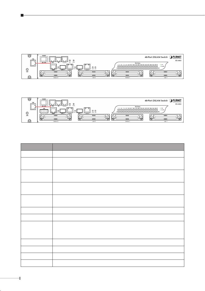
Front Panel
The front panels are shown below.
IDL-4802
IDL-4802-48
Interface Denition
Interface Description
POWER Power On / Off switch.
-48V
FAN
HK
Console
RST A hidden reset button for hardware resetting.
ACO Alarm Cut Off
MGMT
Uplink 1 & 2 Gigabit Ethernet electrical trunk ports.
SFP 1 & 2 Gigabit Ethernet SFP trunk ports.
PHONE 1 & 2 RJ-21 connector for connecting POTS lines.
LINE 1 & 2 RJ-21 connector for connecting DSL lines.
-48V DC Power plug-in.
(*IDL-4802-48)
RJ-45 port for connection with the RJ-45 port on the front panel
of fan card to provide power to the fan.
RJ-50 port for housekeeping inputs and one alarm contact
output.
RS-232 port for system conguration and maintenance. (9600,
8, N, 1)
Ethernet Port connected to LAN for providing system out-band
Telnet control interface, such as system monitor, control or
software upgrade.
Page 5
LED Denition
LED Color Description
Uplink Port connect with 100/1000Mbps
Ethernet link
Orange
Uplink
Green
SYS
ALM
DSL status Green
Green Normal Operation
Red Self-test fail
Green Normal Operation
Red To indicate the system alarm status
On
Off Uplink Port connect with 10Mbps Ethernet link
On Active
Off Inactive
Flash Uplink Port Transmit / receive data
On ADSL Port is activated and linked
Off ADSL Port is Disabled
Flash ADSL Port is activated but not linked
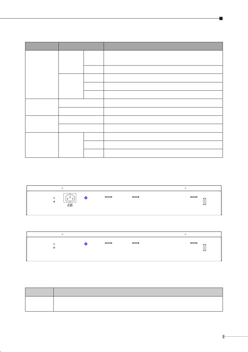
Rear Panel
The rear panels are shown below.
IDL-4802
IDL-4802-48
Port Denition
Port Description
AC PWR
AC Power cord plug-in, 100 - 240VAC is allowed.
(*IDL-4802)
5
Page 6

6
Safety Instruction
The following is the safety instructions for IP DSLAM before installing.
>> The maximum operating temperature of the IP DSLAM is 65ºC. Care must be
taken to allow sufcient air circulation or space between units when the IP DSLAM
is installed inside a closed rack assembly and racks should safely support the
combined weight of all IP DSLAM.
>> The connections and equipment that supply power to the IP DSLAM should
be capable of operating safely with the maximum power requirements of the IP
DSLAM. In the event of a power overload, the supply circuits and supply wiring
should not become hazardous.
>> The AC power cord must plug into the right supply voltage. Make sure that
the supplied AC voltage is correct and stable. If the input AC voltage is over 10%
lower than the standard may cause the IP DSLAM to malfunction.
>> Generally, when installed after the nal conguration, the product must comply
with the applicable safety standards and regulatory requirements of the country in
which it is installed. If necessary, consult for technical support.
>> A rare condition can create a voltage potential between the earth grounds of
two or more buildings. If products installed in separate building are interconnected,
the voltage potential can cause a hazardous condition. Consult a qualied electrical
consultant to determine whether or not this phenomenon exists and, if necessary,
implement corrective action before interconnecting the products. If the equipment
is to be used with telecommunications circuit, take the following precautions:
- Never install telephone wiring during a lightning storm.
- Never install telephone jacks in wet location unless the jack is specially designed for wet location.
- Never touch un-insulated telephone wires or terminals unless the telephone line
has been disconnected at the network interface.
- Caution when installing or modifying telephone lines (other than a cordless tele
phone) during an electrical storm. There is a remote risk of electric shock from
lightning.
- Do not use a telephone or other equipment connected to telephone lines to
report a gas leak in the vicinity of the leak.
-
Page 7

Hardware Installation
STANDARD
FRONT MOUNT
FRONT
MOUNTING
BRACKET
MOUNTING
BRACKET
The PLANET IDL-4802 is a 1.5U high box-type IP DSLAM with rack-mountable
enclosure. It can be installed in a standard 19-inch rack by using the mounting
brackets provided. Mount the shelf on the rack using the large screws provided.
The procedures to connect and wire the system are as follows,
1. Power and Ground Connections
Power Connections
With IDL-4802, connect the AC power cord to the AC supply socket on the rear
panel as below gure, and plug the cord into the external power source. The
voltage must be 100 to 240V AC.
With IDL-4802-48, the DC power interface is a 4-pin terminal block with polarity
signs on the front panel as below gure.
It can be powered from two –48V DC power supply. The DC power connector is a
4P terminal block; 2P is for accommodating one DC power input and other 2P is
for accommodating another DC power input. The DC power should be connected to
a well-fused power supply.
After completing chassis installation, please apply power to the fused power
distribution panel feeding the chassis. When using a DC voltmeter, please check for
proper voltage: -60V ~ -36V DC, and make sure that the polarity is correct.
7
Page 8

8
Ground Connections
Note
¢InCentralOfce:
There should be a CO GND that is adequately grounded. If the measured resistance
from the grounding screw (on the rear panel of the DSLAM, refer to below gure)
to CO GND is less than 5 Ohm, then it can be assumed that the system is well
grounded. If the measured resistance is larger than 5 Ohm, it is recommended
to connect the grounding screw to CO GND using #14 or #12 AWG wire gauge
conductor.
¢InRemoteCabinet:
The IDL-4802 should be grounded by connecting a #14 or #12 AWG conductor
between the grounding screw (on the rear panel of the DSLAM, refer to below
gure) and the earth ground or main grounding bar. The resistance between the
chassis and the grounding bar should be less than 25 Ohm.
Grounding Screw of IDL-4802
Grounding Screw of IDL-4802-48
Ensure that all power sources to the device are turned off during
the installation.
Page 9

2. FAN Cable Connection
1 2 3 4 5 6 7 8
Note
There are two FAN ports on the front panel. One is on the FAN card; the other
is beside the HK port. To make the fans work, you must use an RJ45-to-RJ45
connector cable to connect the two FAN ports.
FANPortRJ-45pinassignment:
3 , 4 5 6 7 8
GND
FAN
ERR1
FAN
ERR2
FAN
ERR3
FAN
Status
3. ADSL and POTS Connections
The IDL-4802 supports 48 ports ADSL subscribers per box. There are four RJ-21
50-pin female connectors on the front panel of the system. Two for ADSL lines and
two for POTS interfaces.
To connect the subscriber lines, use cables with the RJ-21 50-pin male connectors.
When installing, just plug the end of cable with connector into the LINE and PHONE
connectors on the front panel. The other end of the cable is generally tied to the
MDF (Main Distribution Frame).
The MDF Patch panel is optional of standard package.
9
Page 10

10
Please plug-in the RJ-21 cable with connector tenon as below gures.
4. Uplink Interfaces Connections
The system provides two types of trunk interfaces (two ports for each type). There
are electrical (RJ-45) and optical (SFP) interfaces. When both electrical and optical
ports are connected, system will automatically select the interface according to the
priority setting (Fiber rst or Copper rst).
SFP(Mini-GBIC):
Prepare a proper SFP module and install it into the optical trunk port. Then you can
connect ber optics cabling that uses LC connectors or SC connectors (with the use
of an optional SC-to-LC adapter) to the ber optics connector on the trunk port.
Page 11

5. Management Port Connection
The IDL-4802 provides one RJ45 (MGMT) on the front panel for Ethernet interface
connection. To connect the Ethernet interface to PC directly, an Ethernet crossover
cable is required.
6. Console Port Connection
The Console interface on the front panel is the main control interface of the IDL-
4802. To connect the host PC to the console port, a RJ45 (male) connector-to-
RS232 DB9 (female) connector cable is required. The RJ45 connector of the cable
is connected to the COM port of the DSLAM; the DB9 connector of the cable is
connected to the PC COM port.
7. Housekeeping Connection
The IDL-4802 equips with a RJ-50 port (HK) on the front panel to provide four
housekeeping inputs and one alarm contact output. Generally, housekeeping
contacts can connect to environment-sensor-controlled switch to indicate the
operation environment condition.
11
Page 12

12
The HK circuit contains a photo coupler powered by the IDL-4802 to detect the
"open" or "close" status of the loop between HK_IN and HK_COM (users don’t
need to feed 3.3v power into the circuit). As to the alarm output, there is a relay
between ALMOUT and ALMCOM to control the status of the loop to be "OPEN" or
"CLOSE" to the alarm equipment (close between ALMOUT and ALMCOM for alarm;
open if no alarm).
HKPortRJ-50pinassignment:
OperationdiagramofHousekeepingInputsandAlarmContactOutput:
Page 13

WEB Conguration
This section describes how to use Web Conguration Tool to maintain your IP
DSLAM. The IDL-4802 contains a HTTP server. You can login and congure it by
using your Web Browser.
Preparation
Before attempting to congure the IDL-4802, please ensure as below:
Set your computer’s IP with the same network segment of the IP DSLAM.
(Forexample:IDL-4802defaultMGMTIPis192.168.1.1/255.255.255.0)
Then you can set computer’s IP to:
192.168.1.x/255.255.255.0.
(The range for x is from 2 to 253)
Step 1: Using your WEB Browser
Open web browser and type http://192.168.1.1 in the browser’s address box.
This IP is the default MGMT IP address of IDL-4802. Press Enter.
13
Page 14

14
Step 2: Login the IDL-4802
A login page will appear. Please type your username / password and click "Sign
in". (The default username/passwordisadmin/admin)
After you login the IDL-4802, you will see the system information as below.
Page 15

Step 3: Congure the DSL PVC
Go to "Bridge Ë Interface Setup Ë ADSL PVC" setting screen, select the ADSL
port and click “Create” to apply the PVC settings.
(For example, create PVC-1 to Port 1. The default VPI/VCIis0/35)
You can see the Port has been created.
15
Page 16

16
Step 4: Enable the ADSL Port Service
Go to "System Ë ADSL Port Service" setting screen, select the ADSL port and
Admin is "ON". Click "Modify" to make this Port is ON.
You can see the Admin status became to ON.
Page 17

Step 5: Connect the ADSL2/2+ CPE to Patch Panel
Connect the ADSL2/2+ CPE to Patch Panel and congure it, the VPI / VCI value
must be the same with IDL-4802.
After nish setting, the CPE will establish the ADSL connection with IDL-4802. You
can check the connection status as below gure. The Current Status is ON.
Now the clients can access to Internet through IDL-4802.
17
Page 18

18
Step 6: Save the running conguration to Flash
Note
Remember to save your running conguration to the ash, otherwise the settings
will be lost if you power-off IDL-4802.
Go to "Maintenance Ë Database" setting screen, select the "(D) Save Running
CongtoFlash(SystemCong)". There are two partitions on ash, select your
Partition which you want to save and click "Write Running". The conguration will
save to the Flash.
Default Partition is Partition1.
Page 19

Further information
For further detail congurations and information can be found in the user’s manual
CD. If you have any other questions, please contact the local dealer where you
purchasing this product.
19
Page 20

This page is intentionally left blank
 Loading...