

Page 1

Industrial 4G LTE Cellular Wireless
Gateway with 5-Port 10/100/100T
ICG-2510W-LTE/ICG-2510WG-LTE Series
1
Page 2

Trademarks
Copyright © PLANET Technology Corp. 2019.
Contents are subject to revision without prior notice.
PLANET is a registered trademark of PLANET Tec hno logy C orp. All other trademarks belong to their respective
owners.
Disclaimer
PLANET Technology does not warrant that the hardware will work properly in all environments and applications, and
makes no warranty and representation, either implied or expressed, with respect to the quality, performance,
merchantability, or fitness for a particular purpose. PLANET has made every effort to ensure that this User's Manual is
accurate; PLANET disclaims liability for any inaccuracies or omissions that may have occurred.
Information in this User's Manual is subject to change without notice and does not represent a commitment on the part
of PLANET. PLANET assumes no responsibility for any inaccuracies that may be contained in this User's Manual.
PLANET makes no commit me nt to upd ate or kee p curre nt th e information in this User's Manual, and re serv es t he right
to make improvements to this User's Manual and/or to the products described in this User's Manual, at any time
without notice.
If you find information in this manual that is incorrect, misleading, or incomplete, we would appreciate your comments
and suggestions.
FCC Radiation Exposure Statement
This equipment complies with FCC RF radiation exposure limits set forth for an uncontrolled environment. This
equipment should be installed and operated with a minimum distance of 20 centimeters between the radiator and your
body.
This transmitter must not be co-located or operating in conjunction with any other antenna or transmitter.
The antennas used for this transmitter must be installed to provide a separation distance of at least 20 cm from all
persons and must not be co-located or operating in conjunction with any other antenna or transmitter.
FCC Caution:
To assure continued compliance, for example, use only shielded interface cables when connecting to computer or
peripheral devices. Any changes or modifications not expressly approved by the party responsible for compliance
could void the user’s authority to operate the equipment.
This device complies with Part 15 of the FCC Rules. Operation is subject to the following two conditions:
(1) This device may not cause har mful int er fere nce
(2) This device must accept any interference received, including interference that may cause undesired operation.
CE Compliance Statement
This device meets the RED directive 2014/53/EU of EU requirements on the limitation of exposure of the general
public to electromagnetic fields by way of health protection.
The device complies with RF specifications when the device used at 20 cm from your body.
Safety
This equipment is designed with the utmost care for the safety of those who install and use it. However, special
attention must be paid to the dangers of electric shock and static electricity when working with electrical equipment. All
guidelines of this and of the computer manufacture must therefore be allowed at all times to ensure the safe use of the
equipment.
2
Page 3

Manufacture: PLANET Technology Corp.
WEEE Warning
To avoid the potential effects on the environment and human health as a result of the presence of hazardous
substances in electrical and electronic equipment, end users of electrical and electronic equipment should
understand the meaning of the crossed-out wheeled bin symbol. Do not dispose of WEEE as unsorted
municipal waste and have to collect such WEEE separately.
Revision
PLANET ICG-2510W(G)-LTE Series User's Manual
Model: ICG-2510W-LTE and ICG-2510WG-LTE Series
Revision: 1.0 (October, 2019)
Part No: EM-ICG-2510W(G)-LTE Series_v1.0
Manufacture address: 10F., No.96, Minquan Rd., Xindian Dist., New Taipei City 231, Taiwan
3
Page 4

TABLE OF CONTENTS
1. INTRODUCTION .......................................................................................................................... 7
1.1. Packet Contents ....................................................................................................................................... 7
1.2. Product Description ................................................................................................................................. 8
1.3. How to Use This Manual ........................................................................................................................ 13
1.4. Product Features ................................................................................................................................... 14
1.5. Product Specifications ........................................................................................................................... 16
2. INSTALLATION ........................................................................................................................... 19
2.1. Hardware Description ............................................................................................................................ 19
2.1.1. Cellular Gateway Front Panel..................................................................................................................... 19
2.1.2. LED Indications .......................................................................................................................................... 20
2.1.3. Cellular Gateway Upper Panel ................................................................................................................... 21
2.1.4. Wiring the Power Inputs ............................................................................................................................ 21
2.1.5. Wiring the Digital Input/Output and Relay ................................................................................................ 22
2.1.6. Console Line Definition .............................................................................................................................. 22
2.1.7. Dual SIM Cards Installation ........................................................................................................................ 23
2.1.8. Installing MicroSD Card ............................................................................................................................. 24
2.2. Mounting Installation ............................................................................................................................ 25
2.2.1. DIN-rail Mounting ...................................................................................................................................... 25
3. CELLULAR GATEWAY MANAGEMENT ................................................................................ 27
3.1. Requirements ........................................................................................................................................ 27
3.2. Management Access Overview .............................................................................................................. 28
3.3. Web Management ................................................................................................................................. 29
3.4. SNMP-based Network Management ..................................................................................................... 30
4. WEB CONFIGURATION ............................................................................................................ 31
4.1. Configuration Connection ...................................................................................................................... 31
4.2. Accessing the Configuration Web Page .................................................................................................. 31
4
Page 5

Management and Configuration ............................................................................................................ 33
4.3.
4.3.1. Setting ........................................................................................................................................................ 33
4.3.1.1. Basic Setting ........................................................................................................................................... 33
4.3.1.2. DDNS....................................................................................................................................................... 44
4.3.1.3. Clone MAC Address ................................................................................................................................ 45
4.3.1.4. Advanced Routing ................................................................................................................................... 46
4.3.1.5. VLANS ..................................................................................................................................................... 47
4.3.1.6. Networking ............................................................................................................................................. 48
4.3.2. Wireless ..................................................................................................................................................... 52
4.3.2.1. Basic Settings .......................................................................................................................................... 52
4.3.2.2. Wireless Security .................................................................................................................................... 53
4.3.3. Services ...................................................................................................................................................... 56
4.3.3.1. Services ................................................................................................................................................... 56
4.3.4. VPN ............................................................................................................................................................ 60
4.3.4.1. PPTP ........................................................................................................................................................ 60
4.3.4.2. L2TP ........................................................................................................................................................ 62
4.3.4.3. OPENVPN ................................................................................................................................................ 64
4.3.4.4. IPSEC ....................................................................................................................................................... 69
4.3.4.5. GRE ......................................................................................................................................................... 72
4.3.5. Security ...................................................................................................................................................... 74
4.3.5.1. Firewall ................................................................................................................................................... 74
4.3.6. Access Restrictions .................................................................................................................................... 77
4.3.6.1. WAN Access ............................................................................................................................................ 77
4.3.6.2. URL Filter ................................................................................................................................................ 80
4.3.6.3. Packet Filter ............................................................................................................................................ 81
4.3.7. NAT ............................................................................................................................................................ 82
4.3.7.1. Port Forwarding ...................................................................................................................................... 83
4.3.7.2. Port Range Forward ................................................................................................................................ 83
4.3.7.3. DMZ ........................................................................................................................................................ 84
4.3.8. QoS Setting ................................................................................................................................................ 85
4.3.8.1. Basic ........................................................................................................................................................ 85
4.3.8.2. Classify .................................................................................................................................................... 85
4.3.9. Applications ............................................................................................................................................... 86
4.3.9.1. Serial Applications .................................................................................................................................. 86
4.3.10. Admin ...................................................................................................................................................... 87
4.3.10.1. Management ........................................................................................................................................ 88
4.3.10.2. Keep Alive ............................................................................................................................................. 90
4.3.10.3. Commands ............................................................................................................................................ 91
4.3.10.4. Factory Defaults .................................................................................................................................... 91
4.3.10.5. Firmware Upgrade ................................................................................................................................ 92
5
Page 6

4.3.10.6.
4.3.11. Status ....................................................................................................................................................... 93
Backup .................................................................................................................................................. 92
5. APPENDIX A RJ45 PIN ASSIGNMENTS ............................................................................... 94
5.1. A.1 10/100Mbps, 10/100BASE-TX ......................................................................................................... 94
6
Page 7

1. INTRODUCTION
Thank you for purchasing P LANET Industrial 4G LTE Cellular Wireless Gateway . P lease re f er to th e table list below for
the models used in Europe and the U.S.:
4G LTE
GPS
Model Name
ICG-2510W-LTE-EU
FDD TDD
-
B1/B3/B5/B7/B8/B20 B38/B40/B41
ICG-2510WG-LTE-EU
ICG-2510W-LTE-US
█
-
B2/B4/B12
ICG-2510WG-LTE-US
█
“Cellular Gateway” is used as an alternative name in this user ’s manual.
1.1. Packet Contents
Open the box of the Cellular G ate way and carefully unpack it. The box should contain the following items:
1. Industrial 4G LTE Cellular Wireless Gateway x 1
2. Quick installation guide x 1
3. I/O connector x 2
4. Power connector x 1
5. Ethernet cable x 1
6. Console cable x 1
7. 4G LTE antenna x 2
8. Wi-Fi antenna x 1
9. GPS antenna x 1 (for ICG-2510WG-LTE)
10. DIN-rail kit x 1
11. Side panel with two screws x 1
12. Antenna dust cap x 4 (ICG-2510W-LTE x 3)
If any item is found missing or damaged, please contact your local reseller for replacement.
7
Page 8
1.2. Product De s c ription
Making Network Connection Easy with 4G LTE Cellular Gateway
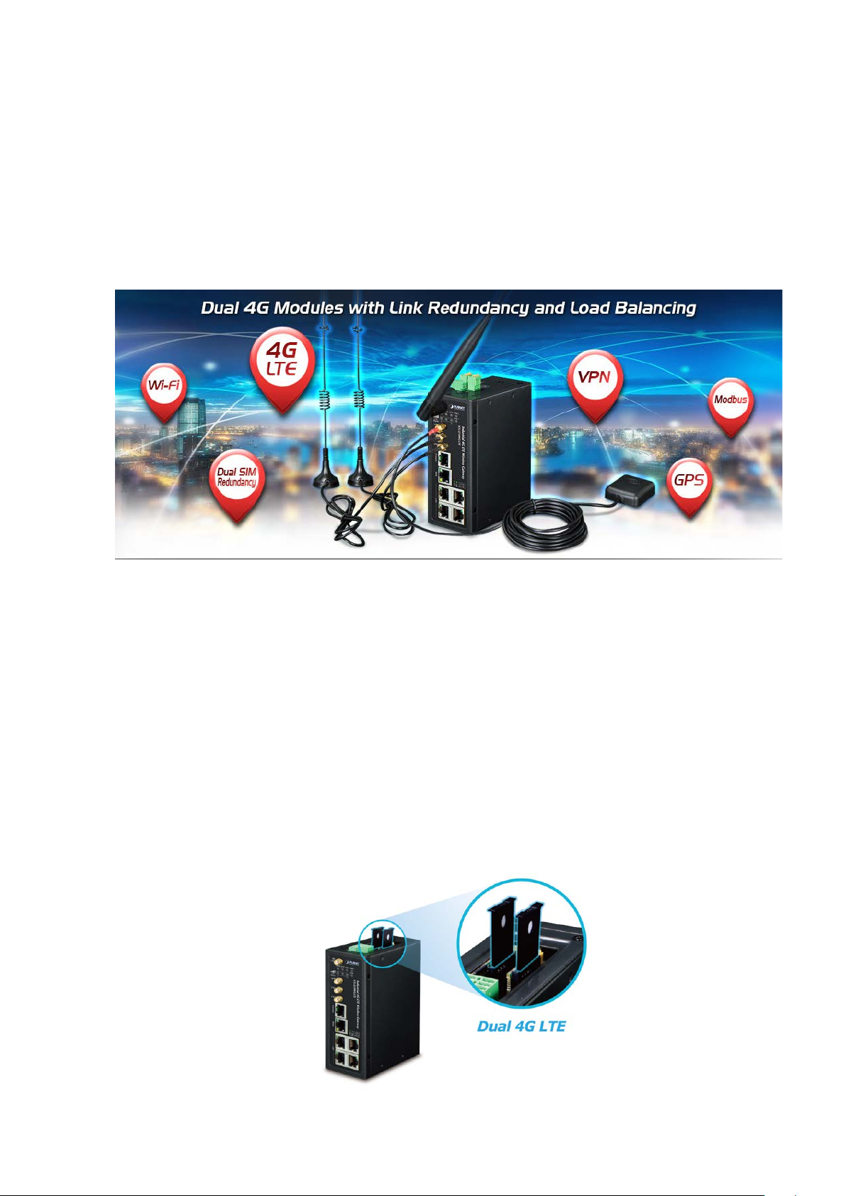
PLANET ICG-2510W(G)-LTE series is a reliable, secure and high-bandwidth communications industrial-grade cellular
gateway for demanding mobile applications, M2M (machine-to-machine) and IoT deployments. It features 4G LTE
(Long Term Evolution), 2.4G/5G Wi-Fi, five Ethernet ports (4 LAN and 1 WAN), serial console port, DI and DO
interfaces, and VPN technology bundled in a compact yet rugged metal case. It establishes a fast cellular connection
between Ethernet and serial port equipped devices.
High-performance 4G LTE
The ICG-2510W(G)-LTE series supports LTE 2x1 DL MIMO technology which can reach a download (DL) speed of up
to 150Mbps and an upload (UL) speed of 50Mbps. The Cellular Gateway also supports multi-band connectivity
including LTE FDD/TDD, WCDMA and GSM for a wide range of applications.
Dual SIM Design
To enhance reliability, the ICG-2510W(G)-LTE series is equipped with dual SIM slots that support failover and roaming
over to ensure uninterrupted connectivity for mission-critical cellular communications. Besides, the ICG-2510W(G)
series supports load balance function to improve network efficiency. It provides a more flexible and easier way for
users to create an instant network sharing service via 4G LTE whenever in public places like transportation, outdoor
event, etc.
8
Page 9
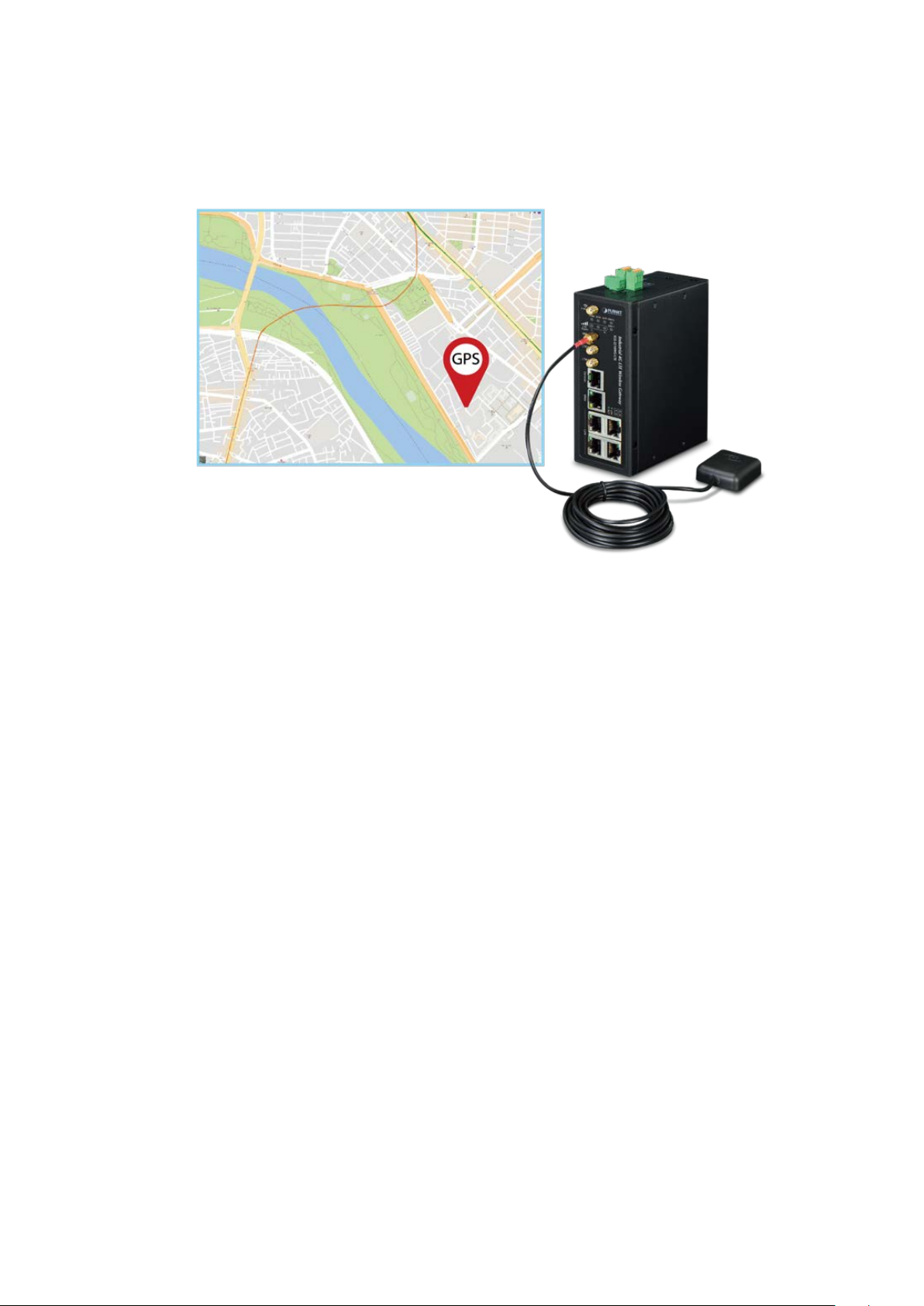
GPS Included
The ICG-2510WG-LTE is equipped with one convenient feature and that is GPS (global positioning system). It is a
positioning system based on a network of satellites that continuously transmits necessary data. More signals
transmitted from more satellites can triangulate its location on the ground, meaning any location can be easily tracked.
Dual-band WLAN Solution
PLANET ICG-2510W(G) series, adopting the IEEE 802.11b/g/n/ac standard, provides a high-speed transmission of
power and data, meaning two remote nodes in the 5GHz frequency band can be bridged. The 2.4GHz wireless
connection can also be used simultaneously. The Wireless Protected Access (WPA/W PA2 with TKIP/AES) and
Wireless Encryption Protocol (WEP) features enhance the level of transmission security and access control over
wireless LAN.
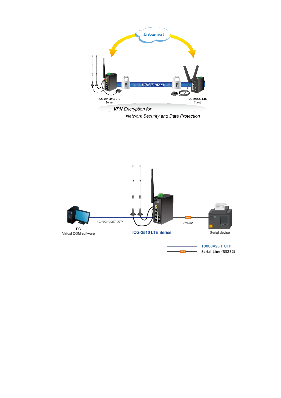
Cost-effective VPN Solution
The ICG-2510W(G)-LTE series provides a complete data security and privacy feature f or acce ss and exchange of
sensitive data. The full VPN ca pabi lity of the ICG-2510W(G)-LTE series including built-in PPTP, L2TP, OpenVPN,
GRE and IPSec VPN functions with DES/3DES/AES encryption and MD5/SHA-1/SHA-2 authentication makes the
shared connection more secure and flexible. The IPSec VPN also makes the private tunnel over Internet more secure
for enterprises doing business t rans act ion s.
9
Page 10
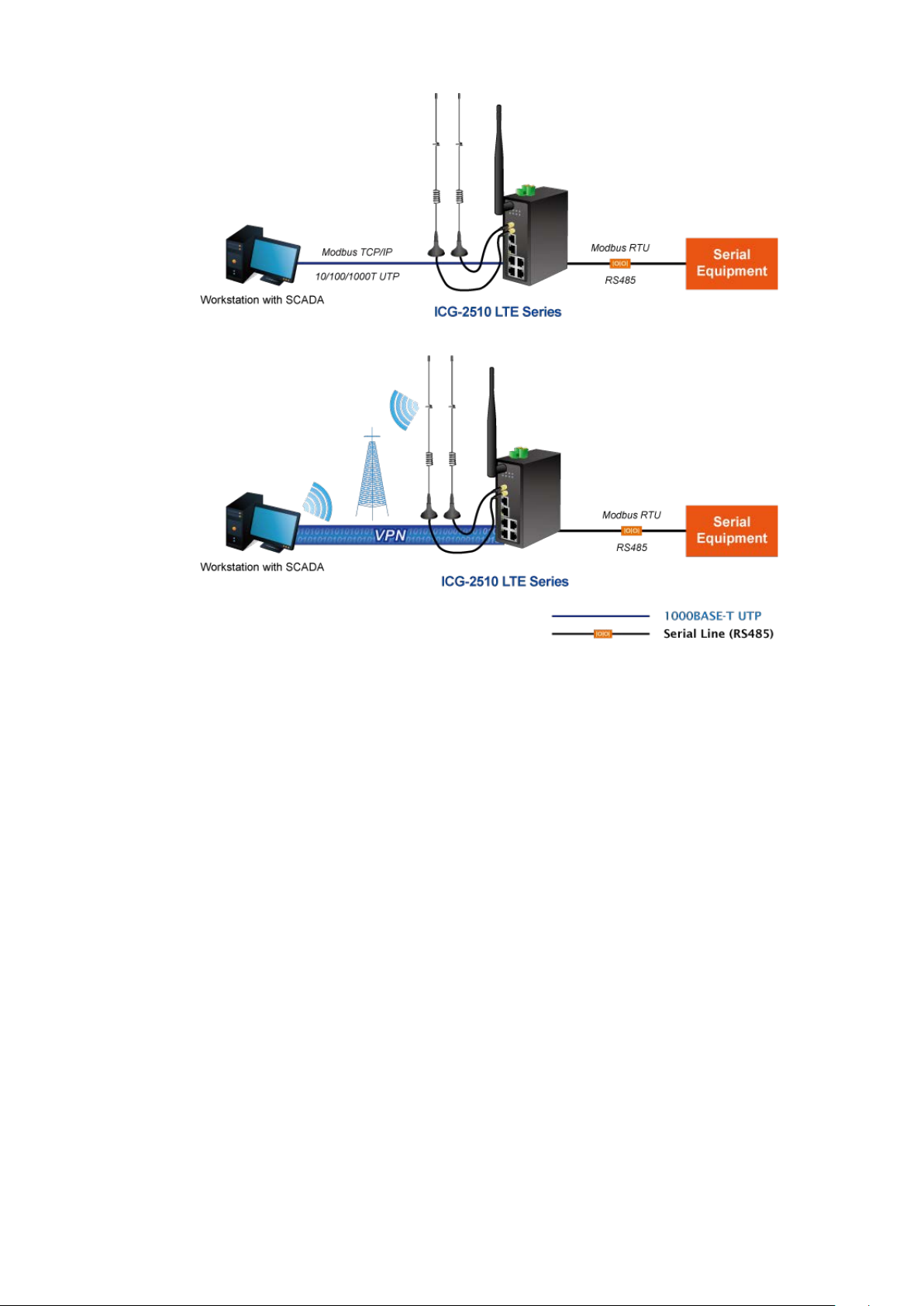
Remote Manageable Solution for Ethernet to RS232/RS485 Application
PLANET ICG-2510W(G)-LTE series’ serial RS232/RS485 communication interface can be converted over the Fast
Ethernet networking. It can op erate as a virtu al server or clie nt where IP-ba se d s eria l eq uipment can be managed. The
ICG-2510W(G)-LTE series helps save the network administrator’s valuable time in detecting and locating network
problems, rather than visual inspection of cabling and equipment.
10
Page 11
11
Page 12
Superior Management Functions
For networking management features, the ICG-2510W(G)-LTE series provide s suc h funct i ons as DHCP server, DMZ
and port forwarding, as well as full secure functions including Network Address Translation (NAT), WAN access policy,
URL/Packet/MAC filtering. The ICG-2510W(G)-LTE series has 4G and WAN connection failover characteristics, which
can automatically switch over to the redundant, stable WAN connection to keep users always online without missing
any fascinating moments.
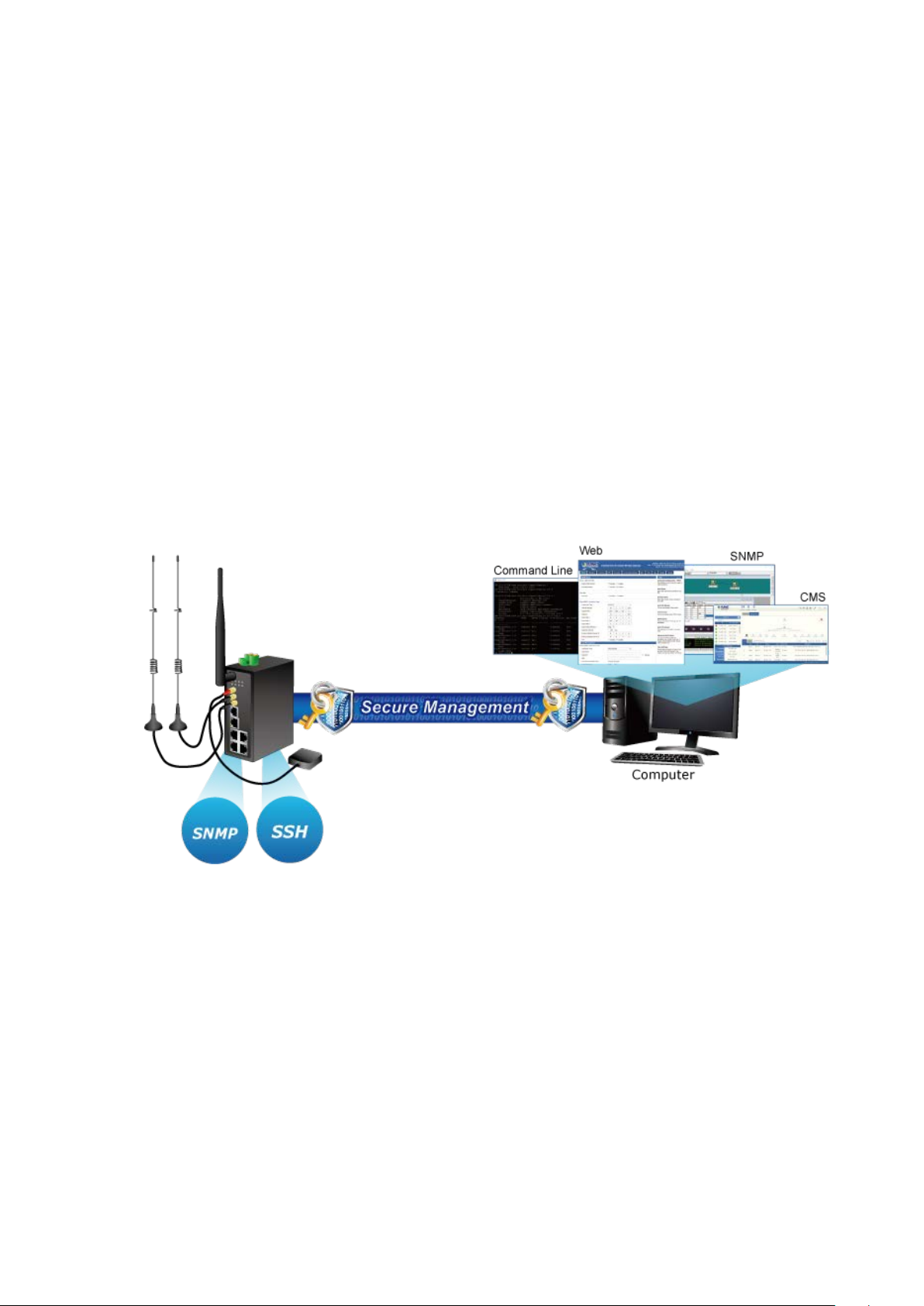
User-friendly and Secure Management
For efficient management, the ICG-2510W(G)-LTE series is equipped with console, web , SNMP and CMS (Central
Management System) management interfaces. With the built-in web-based management interface, the
ICG-2510W(G)-LTE series offers an easy-to-use, platform-independent management and configuration facility. The
ICG-2510W(G)-LTE series supports SNMP and it can be managed via any management software based on the
standard SNMP v1 or v2 Protocol. Moreover, the ICG-2510W(G)-LTE s eries offers the remotely secure management
by supporting SSH connection where the packet content can be encrypted at each session. The CMS is able to
manage multiple devices and achieve instant status.
12
Page 13

1.3. How to Use Thi s Manual
This User Manual is structured as follows:
Section 2, INSTALLATION
The section explains the functions of the Cellular Gateway and how to physically install the Cellular Gateway.
Section 3, CELLULAR GATEWAY MANAGEMENT
The section contains the information about the software function of the Cellular Gateway.
Section 4, WEB CONFIGURATION
The section explains how to manage the Cellular Gateway by Web interface.
Section 5 Appendix A
The section contains cable inf or mat ion of the Cellular Gateway.
13
Page 14

1.4. Product Fe atures
Benefits
■ Dual module SIMs for network load balancing and redundancy
■ Wi-Fi compliant IEE E 802.11b/g/n/ac dual-band for mobile client connectivity
■ 5-port Gigabit Ethernet, built-in redundant VRRP protocol
■ 2 DI, 1 DO and 1 serial console port (RS232 or RS485) for Modbus applications
■ Multiple VPNs with IPSEC, OpenVPN, RRTP, L2TP, GRE and VPN Failover
■ Full security with VLAN, NAT, DMZ, static routing, firewall and IP/MAC/port filtering
■ Supports CMS for remote management
■ -35 to 75 degrees C operating temperature and fanless design
■ GPS antenna allows to detect the location via sat nav system (for ICG-2510WG-LTE only)
Physical Port
■ Four 10/100/1000BASE-T RJ45 LAN ports, auto-negotiation, auto MDI/MD I-X
■ One 10/100/1000BASE-T RJ4 5 WAN port, auto-negotiation, auto MDI/MDI-X
■ Two 4G LTE antennas
■ One 2.4G/5G WiFi antenna
■ Two SIM card slots
■ One GPS antenna ( for ICG-2510WG-LTE )
■ One serial console port ( RS232 or RS485)
■ One reset button
■ One MicroSD slot to save files for serial port data
Cellular Interface
■ Supports multi-band connectivity with FDD LTE/ TDD LTE/ WCDMA/ GSM/ LTE Cat4
■ Supports failover and load band lancing
■ Built-in SIM and broadband backup for network redundancy
■ Two detachable antennas for 4G LTE connection
■ LED indicators for signal strength and connect ion stat us
Wi-Fi Interface
■ Complies with IEEE 802.11b/g/n/ac 2.4/5GHz
■ Supports AP, Client, Repeater and Repeater Bridge modes
■ One detachable dual band antenna for wireless connection
■ 64/128-bit WEP, WPA/ WP A 2 with TKIP/AES encryption
■ LED indicator for connection status
Industrial Case and Installation
■ IP30 metal case
■ DIN-rail/desktop design
■ Power requirement: 9~36V DC
■ Supports EFT protection for 1.5KV DC power and 15KV DC Ethernet ESD protection
■ -35 to 75 degrees C operating temperature
Digital Input and Digital Output
■ 2 digital input (DI)
■ 1 digital output (DO)
■ 1 relay
14
Page 15

Advanced Features
■ Supports NAT, demilitarized zone (DMZ), port forwarding and virtual IP mapping
■ Supports VLAN to improve the performance of a network or apply appropriate security features
■ Supports static routing and dynamic routing for gateway and router operating modes
■ Supports QoS to manage WAN bandwidth
■ Supports PPTP, L2TP, OPENVPN, IPSec and GRE VPN modes
■ Supports IPSec (3DES, AES128, AES256, MD5, SHA1, SHA2-256, SHA2-512)
■ Supports TCP, UDP, TCP Server and Modbus TCP
■ Supports Dynamic DNS and PLANET DDNS
■ Provides Firewall and access policy functions
■ Supports WAN connection types: DHCP-4G, DHCP Client, Static IP, PPPoE Client, 3G Link1, 3G Link 2,
DHCP-Backup 4G
■ Secures network connection
− WAN access
− URL filter
− Packet filter
− MAC filter
Management
■ Switch management interfaces
− Console/Telnet Command Line interface
− Web user interface management
− SNMP v1, v2c
− SSH secure access
■ Keep alive (schedule reboot)
■ System Maintenance
− Firmware upload via HTTP
− Reset button for system rebooting or resetting to factory default
− Configuration backup and restore
■ System log
■ Remote system log
■ NTP (Network Time Protocol) client support
■ Support CMS to manage multiple devices
15
Page 16

Hardware Specifications
SIM Interface
2 SIM card slots with mini SIM card tray
Cellular Antenna
2 5dBi external antennas with SMA connectors for LTE
J connector
for dual-band Wi-Fi
SMA connectors - 3m
Relay: AC 250V/DC 30V, 1A
2 removable 3-pin terminal block for DI/DO and relay interface
Storage
1 MicroSD (TF) slot for saving serial port data
Switch Architecture
Store-and-Forward
Back pressure for half duplex
Reset Button
< 15 sec: Factory default
Surge Protection
ESD Protection
15KV DC
Enclosure
IP30 metal case
Installation
DIN rail, desktop
1.5. Product S pe ci f ications
Product ICG-2510W-LTE ICG-2510WG-LTE
Copper Ports
Serial Interface
Wi-Fi Antenna
GPS Antenna -
DI & DO Interfaces
4 LAN 10/100/1000BASE-T RJ45 auto-MDI/MDI-X ports
1 WAN 10/100/1000BASE-T RJ45 auto-MDI/MDI-X port
DB9 to RJ45 serial console port
TCP/UDP PAD mode
Modbus (ASCII, DTU, variable)
PPP
Reverse Telnet
1 1dBi (2.4~2.5G)/3dBi (5.15~5.85G) external antenna with RP-SMA-
2 Digital Input (DI)
1 Digital Output (DO)
1 Relay
Input ON Voltage: DC 5 -30 V
Input OFF Voltage: DC 0-3 V
Output < 50mA@DC 30V
1 28dB gain external antennas with
Connector
Flow Control
LED
1 removable 2-pin terminal block for power input
IEEE 802.3x pause frame for full duplex
1.5KV DC
System:
PWR (Blue)
SYS (Blue)
Wireless Interface :
WiFi Active (Blue)
Ethernet Interfaces (Port1-4 and WAN Port):
16
Page 17

Dimensions (W x D x H)
133 x 115.7 x 45 mm
Weight
564g
Power Requirements – DC
Power Consumption
8.4 watts/28.6 BTU
Multi Band Supports
GSM/EDGE B3/B8 (1800/900)
LTE Data Rate
1.4/3/5/10/15/20MHz bandwidth: 150Mbps (DL), 50Mbps (UL)
Wireless Specifications
Standard
IEEE 802.11 b/g/n/ac
Wireless Mode
Band Mode
2.4G / 5G concurrent mode
ETSI: 5.180~5.700GHz
*5GHz channel list will vary in different countries according to their regulations.
Channel Width
Personal Mixed, WPA2 Enterprise Mixed
Data Rate
Up to 300Mbps
(dBm)
Max. Clients
Advanced Functions
IPSec
EU Model
LNK/ACT (Green)
LTE SIM and Signal :
SIM1 and SIM2 (Blue)
LTE signal: High and low (Blue)
9~36V DC, 1.5A
FDD LTE B1/B3/B5/B7/B8/B20 (2100/1800/850/2600/900/800)
TDD LTE B38/B40/B41 (2600/2300/2500)
WCDMA B1/B5/B8 (2100/850/900)
US Model
Frequency Range
Operating Channels
FDD LTE B2/B4/B12 (1900/AWS1700/700)
WCDMA B2/B4/B5 (1900/AWS1700/850)
AP, Client, Repeater, Repeater Bridge
2.4GHz
FCC: 2.412~2.462GHz
ETSI: 2.412~2.472GHz
5GHz
FCC: 5.180~5.240GHz, 5.745~5.825GHz
FCC: 36, 40, 44, 48, 149, 153, 157, 161, 165 (9 Channels)
ETSI: 36, 40, 44, 48, 52, 56, 60, 64, 100, 104, 108, 112, 116, 132, 136, 140
(16 Channels)
20MHz, 40MHz, 80MHz
Encryption Security
Max. Trans mit Po wer
VPN
WEP, WPA Personal, WPA Enterprise, WPA2 Personal, WPA2 Enterprise, WPA2
26
30
PPTP server and PPTP client
L2TP server and L2TP client
Open server and Open client
17
Page 18

DHCP-Backup 4G
Secure Network
WAN access, URL filter, Packet filter, MAC filter
Management
Interfaces
Interfaces
Standards Conformance
Regulatory Compliance
CE
RFC 2068 HTTP
Environment
Relative Humidity: 90%@60 degrees C (non-condensing)
Relative Humidity: 90%@60 degrees C (non-condensing)
GRE
Tunnel Number
PPTP: 1
L2TP: 1
OPENVPN: 1
IPSec: 12
GRE: 12
WAN Connection Types
Other
Basic Management
Secure Management
SNMP MIBs
DHCP-4G, DHCP Client, Static IP, PPPoE Client, 3G Link1, 3G Link 2,
Supports demilitarized zone (DMZ)
Supports QoS for bandwidth management
Supports VLAN, 15 VLAN ID
Supports Modbus TCP (only functions with console)
Supports Port Forwarding
Supports Dynamic DNS and PLANET DDNS
Supports NTP client
Console, Telnet, HTTP, HTTPS, SNMP v1, v2c, CMS
SSH, Firewall
RFC 1158 MIB, RFC 1213 MIB, RFC 1269 MIB, RFC 1271 MIB, RFC-1285 MIB,
RFC 1316 MIB, RFC 1381 MIB, RFC 1382 MIB, RFC 1414 MIB
IEEE 802.3 10BASE-T
IEEE 802.3u 100BASE-TX
IEEE 802.3ab Gigabit 1000BASE-T
Standards Compliance
Operating
Storage
IEEE 802.3x flow control and back pressure
RFC 768 UDP
RFC 791 IP
RFC 792 ICMP
Temperature: -35 ~ 75 degrees C
Temperature: -40 ~ 85 degrees C
18
Page 19
2. INSTALLATION
This section describes the hardware features and installation of the Industrial Cellular Gateway on the desktop or
mounting. For easier management and control of t he Industrial Cellular Gateway, familiarize yourself with its display
indicators and ports. Front panel illustrations in this chapter display the unit LED indicators. Before connecting any
network device to the Industrial Cellular Gateway, please read this chapter completely.
2.1. Hardware Description
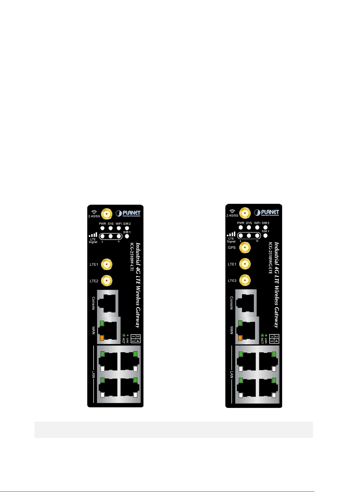
2.1.1. Cellular Gateway Front Panel
The front panel provides the monitoring of the Cellular Gateway’s simple interfaces. Figure 2-1 & 2-2 shows the front
panels of the Industrial Cellular Gateways.
Figure 2-1 ICG-2510W-LTE Front Panel Figure 2-2 ICG-2510WG-LTE Front Panel
19
Page 20
Reset Button Pressed and Released
Function
configuration. Industr ial Ce llular Gateway will then reboot an d
Subnet mask: 255.255.255.0
LED
Color
Function
Lights
Indicates the system is powered on.
Off
Indicates the system is powered off.
Blinking
Indicates the system works properly.
Off
Indicates the system does not work.
Lights
Indicates the Wi-Fi is active.
Off
Indicates the Wi-Fi is not active.
(L)
(H)
Lights
Indicates the SIM1 or SIM2 is connecting successfully.
SIM card inserted.
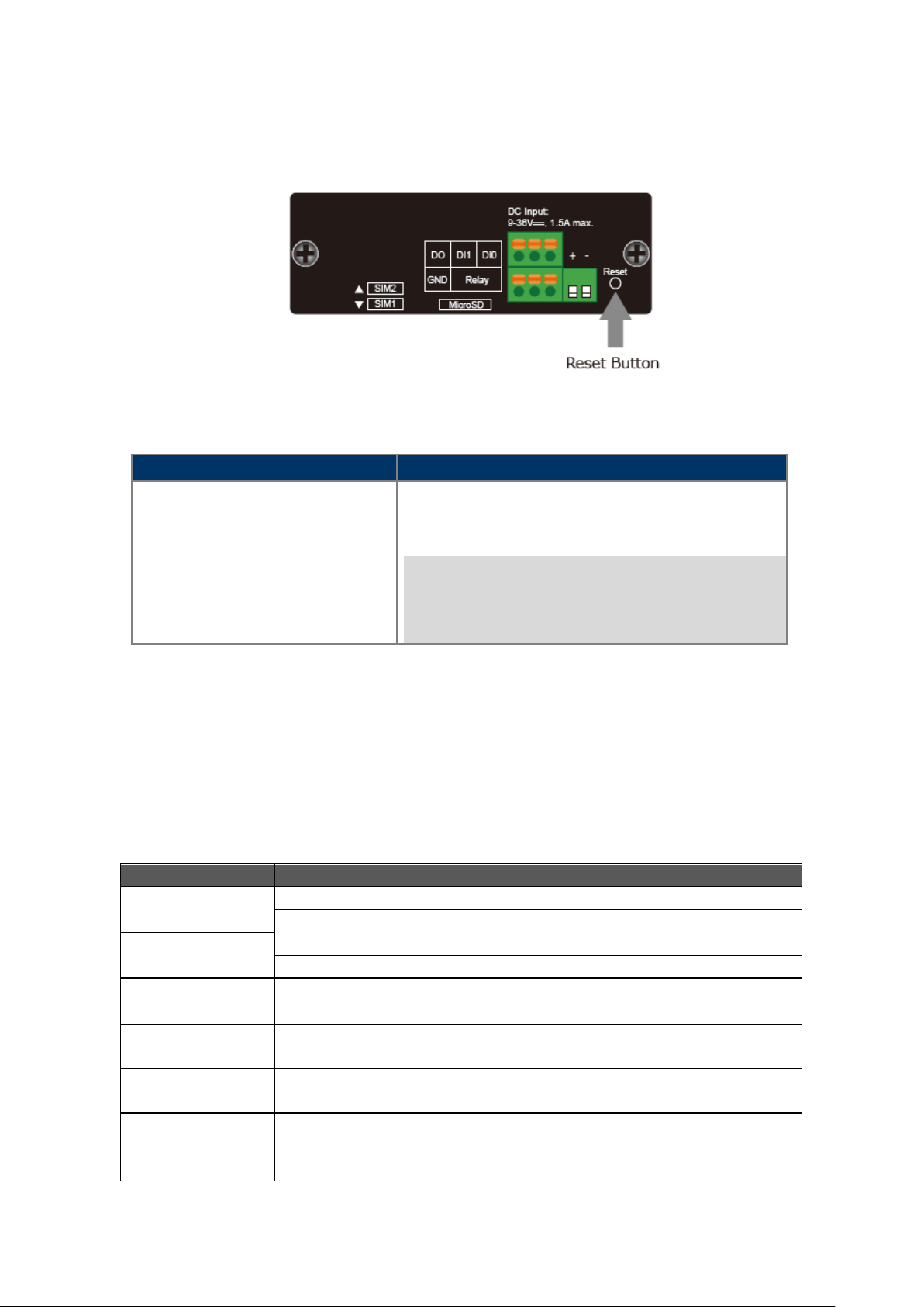
Reset Button
On the front of the ICG-2510W(G)-LTE series, the reset button is designed to reboot the Industrial Cellular Gateway
without turning off and on the power. The following is the summary table of the reset button functions:
Figure 2-3 Rest Button of ICG-2510W(G)-LTE Series
Reset the Industrial Cellular Gateway to Factory Default
load the default settings shown below :
> 15 sec: Factory Default
。 Default username: admin
。 Default password: admin
。 Default IP address: 192.168.1.1
。
2.1.2. LED Indications
The front panel LEDs indicate instant status of port links, data activity and system power; it helps monitor and
troubleshoot when needed.
System
PWR Blue
SYS Blue
Wi-Fi Blue
LTE Signal
LTE Signal
SIM1 & 2 Blue
Blue Lights Indicates the signal is low.
Blue Lights Indicates the signal is normal or high.
Off
Indicates the SIM1 or SIM2 is connecting unsuccessfully or no
20
Page 21
LED
Color
Function
Lights
Indicates that the link is successfully established.
Blinking
Indicates that the port is actively sending or receiving data.
LED
Color
Function
Lights
Indicates that the link is successfully established.
Blinking
Indicates that the port is actively sending or receiving data.
Input
10/100/1000BASE-T LAN Port Interfa ces (Po rt-1 to Port-4)
Ethernet Green
10/100/1000BASE-T WAN Port Interface
Ethernet Green
2.1.3. Cellular Gateway Upper Panel
The upper panel of the Industrial Cellular Gateway consists of three terminal block connectors. Figure 2-4 shows the
upper panel of the Cellular Gateway.
Figure 2-4: ICG-2510W(G)-LTE Series Upper Panel
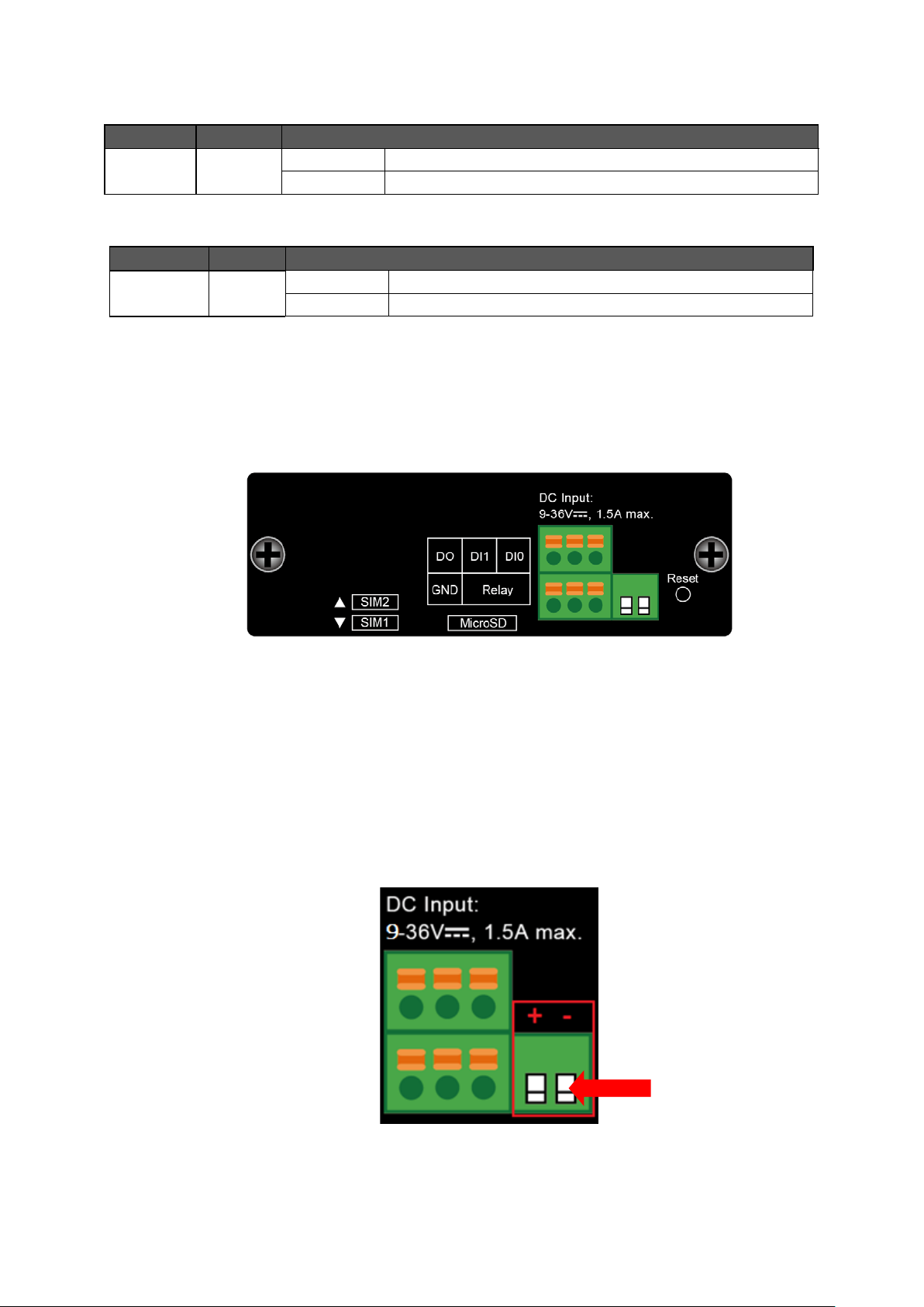
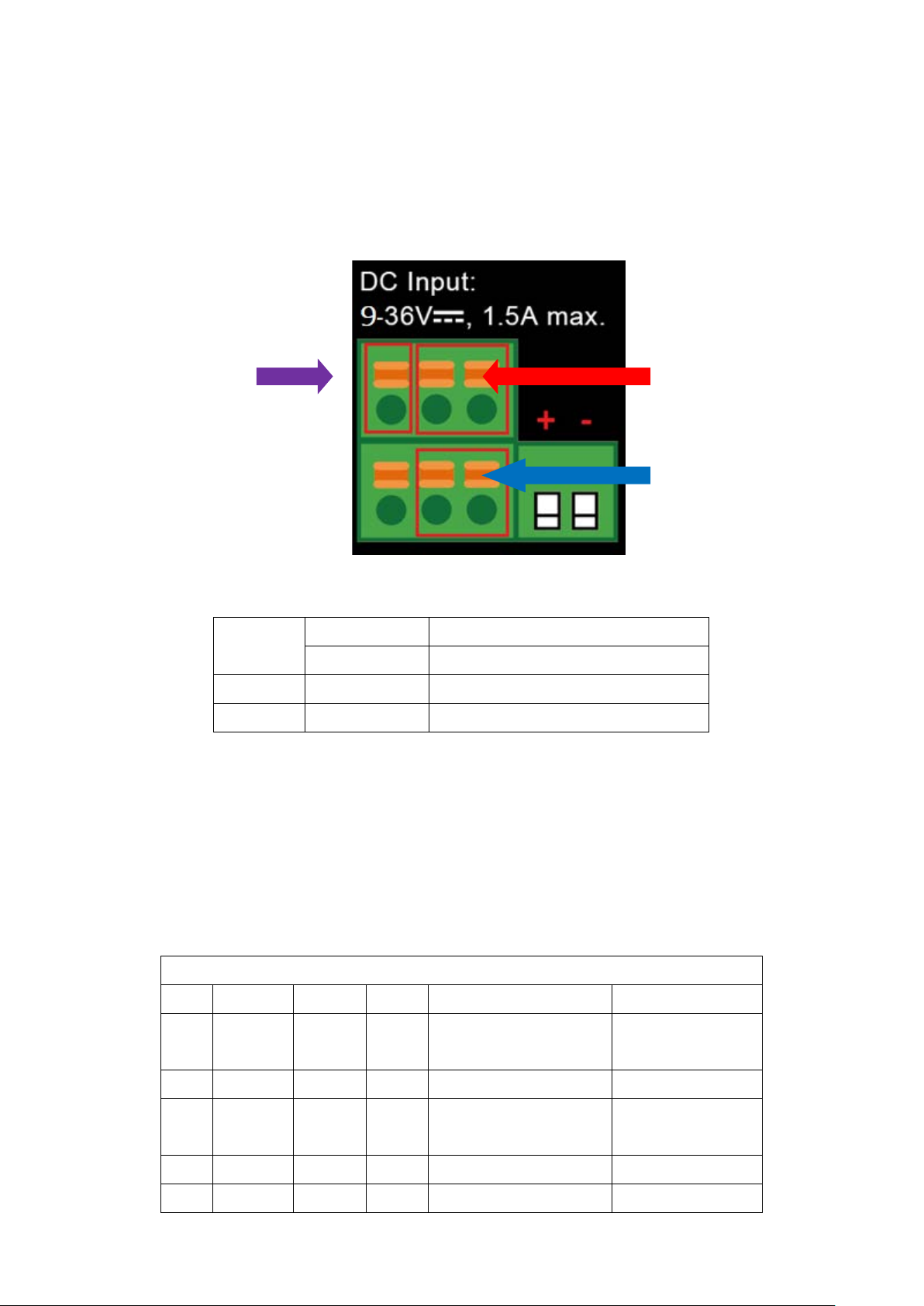
2.1.4. Wiring the Power Inputs
The 2-contact terminal bl oc k conne ctor on t he top panel of Industrial Cellular Gatew ay is used for one DC power input.
The power input range is from 9 to 36V DC. Please follow the steps below to insert the power wire.
1. Please read the above description of upper panel carefully before inserting positive/negative DC power wires
into the 2-contact terminal block connector.
2. Confirm that the positive/negative DC power wires will not fall off.
Power
Figure 2-5: Wiring the Power Inputs
21
Page 22
l Input
Output
2.1.5. Wiring the Digital Input/Output and Rela y
The two 3-contact terminal block connectors on the top panel of ICG-2510W(G)-LTE Series is used for Digital Input,
Digital Output and Relay.
Digital
Digita
Relay
Figure 2-6 Wiring the DI/DO Inputs and Relay
Input ON 5 to 30 VDC
DI
Input OFF 0 to 3 VDC
DO Output < 50mA @ 30VDC
RELAY Load capability 1A 250VAC/30VDC
2.1.6. Console Line Definition
Insert the RJ45 end of the console cable into the RJ45 outlet with sign “console”, and insert the DB9F end of the
console cable into the RS232 serial interface of user’s device.
The signal connection of the console cable is as follows:
Console line definition (RS232 )
RJ45 Color Signal DB9F Description Dir (Router)
1
White/
Orange
2 Orange B 6 RS485-B Input/Output
White/
3
Green
4 Blue DCD 1 Data Carrier Detect Output
5 White/ GND 5 System Ground
A 8 RS485-A Input/Output
RXD 2 Receive Data Output
22
Page 23
M
into the slot or else it w ill get
stuck.
Blue
6 Green TXD 3 Transmit Data Input
White/
7
Brown
8 Brown RTS 7 Request To Send Input
DTR 4 Data Terminal Ready Input
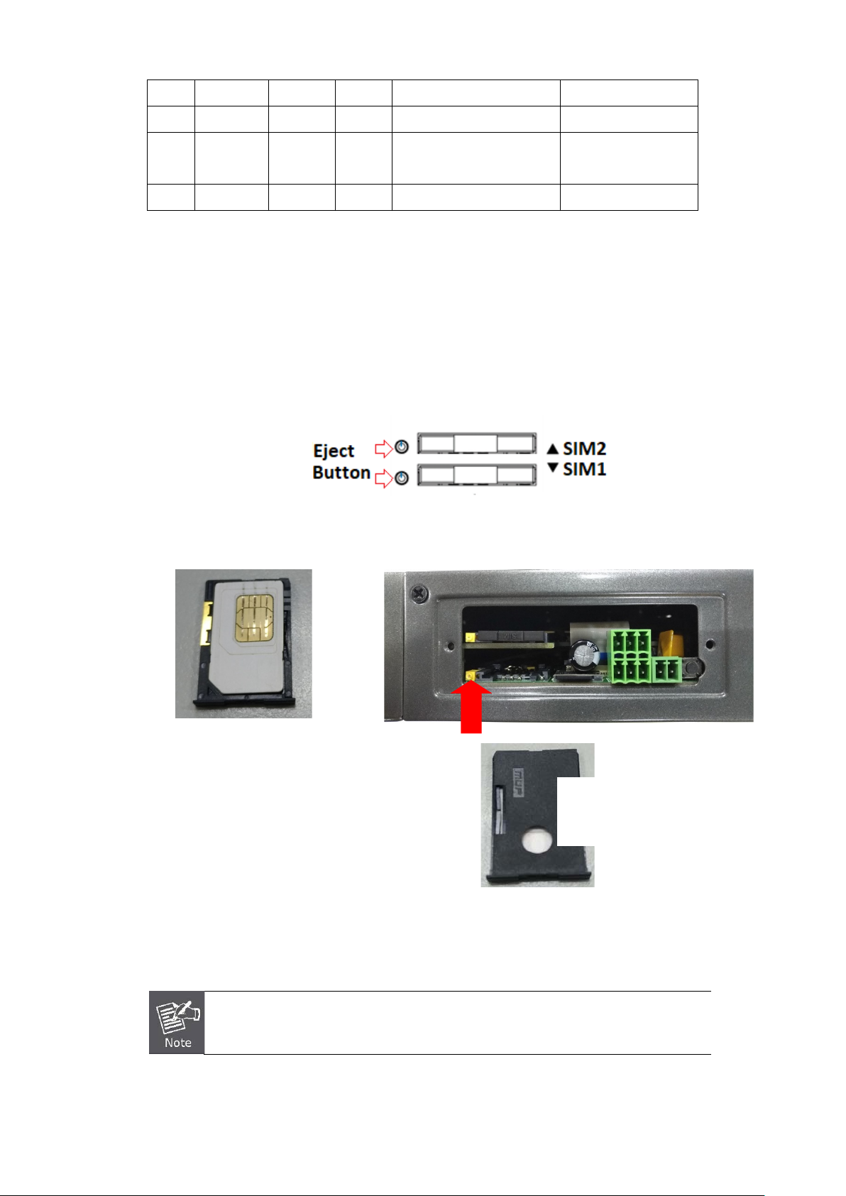
2.1.7. Dual SIM Cards Installation
1. Before inser ting or re moving th e SIM card, ens ure th at the pow er has been t urned off and the power connector
has been removed from Cellular Gateway.
2. Unscrew the screws of upper panel.
3. Press the button with a paper clip or suitable tool to eject the SIM card from the drawer.
4. Insert the SIM card with the contact facing up and align the SIM card tray properly with the slot. Make sure the
tray is inserted into the slot correctly.
5. Slide the tray back into the slot to lock in place.
6. Tighten the screws of the upper panel.
Inserting the tray
into the slot
ake sure the direction is right when sliding the SIM card tray
Turn off the Cellular Gateway before taking the SIM card.
23
Page 24
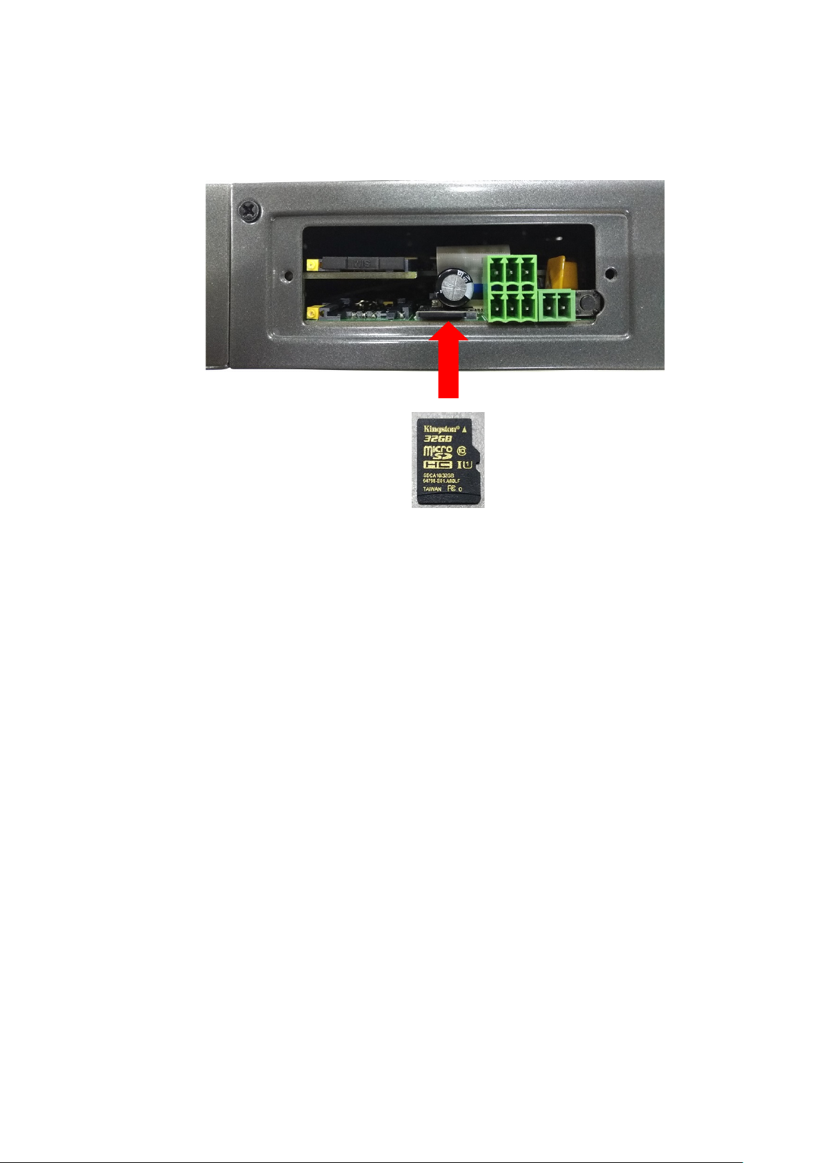
2.1.8. Installing MicroSD Card
The ICG-2510W(G)-LTE series provides a MicroSD card slot . Refer to the SIM card installation method for inserting
the MircoSD card.
24
Page 25

2.2. Mounti ng Installation
This section describes how to install your Industrial Cellular Gateway and make connections to the Industrial Cellular
Gateway. Please read the following sections and perform the procedures in the order being presented. To install your
Industrial Cellular Gateway on a desktop or shelf, simply complete the following steps.
2.2.1. DIN-rail Mounting
The DIN-rail is screwed on the Industrial Cellular Gateway when out of factory. Please refer to the following figures to
screw the DIN-rail on the Industrial Cellular Gateway. To hang the Industrial Cellular Gateway, follow the steps below:
Step 1: Screw the DIN-rail bracket on the Industrial Cellular Gateway.
25
Page 26

Step 2: Place the bottom of DIN-rail bracket lightly into the track.
Step 3: Check whether the DIN-rail bracket is tightly on the track.
Step 4: Please refer to the following procedures to remove the Industrial Cellular Gateway from the track.
Step 5: Lightly pull out the bottom of DIN-rail bracket to remove it from the track.
26
Page 27

I
Cellular
Gateway.
3. CELLULAR GATEWAY MANAGEMENT
This chapter explains the methods that you can use to configure management access to the Industrial Cellular
Gateway. It describes the types of management applications and the communication and management protocols that
deliver data between your management device (workstation or personal computer) and the system. It also contains
information about port connection options.
This chapter covers the following topics:
Requirements
Management Access Overview
Web Management Access
SNMP Access
Standards, Protocols and Related Reading
3.1. Requirements
Workstations running Windows 2000/XP, 2003, Vista/7/8, 2008, MAC OS9 or later, Linux, UNIX or other platforms
are compatible with TCP/IP protocols.
Workstation is installed with Ethernet NIC (Network Interface Card).
Ethernet Port connection
• Network cables -- Use standard network (UTP) cables with RJ45 connectors.
The above Workstation is installed with Web browser and Java runtime environment plug-in.
t is recommended to use Internet Explorer 8.0 or above to access Industrial
27
Page 28

3.2. Management Access Overview
The Industrial Cellular Gateway gives you the flexibility to access and manage it using any or all of the following
methods:
Web browser interface
An external SNMP-based network management application
The Web brow ser i nter fa ce s are embedded in the Industrial Cellular Gatew ay software and are available f or i mme dia te
use. Each of these management methods has their own advantages. Table 3-1 compares the two management
methods.
Method Advantages Disadvantages
• Ideal for conf igur ing t he
Web
Browser
SNMP
Agent
Cellular Gateway remotely
• Compatible with all popular
browsers
• Can be accessed from any
location
• Most visually appealing
• Communicates with Cellular
Gateway functions at the MIB
level
• Based on open standards
Table 3-1 Comparison of Management Methods
• Securi ty can be compromised
(hackers need to only know the IP
address and subnet mask)
• May encounter lag times on poor
connections
• Requires SNMP manager software
• Least visually appealing of all three
methods
• Some settings require calculations
• Securi ty can be compro mised
(hackers need to only know the
community name)
28
Page 29
3.3. Web Management
The Industrial Cellular Gateway offers management features that allow users to manage the Industrial Cellular
Gateway from anywhere on the network through a standard browser such as Microsoft Internet Explorer. After you set
up your IP address for the cellular gateway, you can access the Industrial Cellular Gateway's Web interface
applications directly in your Web browser by entering the IP address of the Industrial Cellular Gateway.
Figure 3-1 Web Management
You can then use your Web browser to list and manage the Industrial Cellular Gateway con figuration parameters from
one central location. Web Management requires either Microsoft Internet Explorer 8.0 or later, Google Chrome,
Safari or Mozilla Firefox 1.5 or later.
Figure 3-2 Web Main Screen of Industrial Cellular Gateway
29
Page 30

3.4. SNMP-based Network Management
You can use an external SNMP-based application to configure and manage the Industrial Cellular Gateway, such as
SNMPc Network Manager, HP Openview Network Node Management (NNM) or What’s Up Gold. This management
method requires the SNMP agent on the cellular gateway and the SNMP Network Management Station to use the
same community string. This management method, in fact, uses two community strings: the get community string
and the set community string. If the SNMP Network Management Station only knows the set community string, it can
read and write to the MIBs. However, if it only knows the get community string, it can only read MIBs. The default get
and set community strings for the Industrial Cellular Gateway are public.
Figure 3-3 SNMP Management
30
Page 31

4. WEB CONFIGURATION
This chapter describes how to configure and manage the cellular gateway
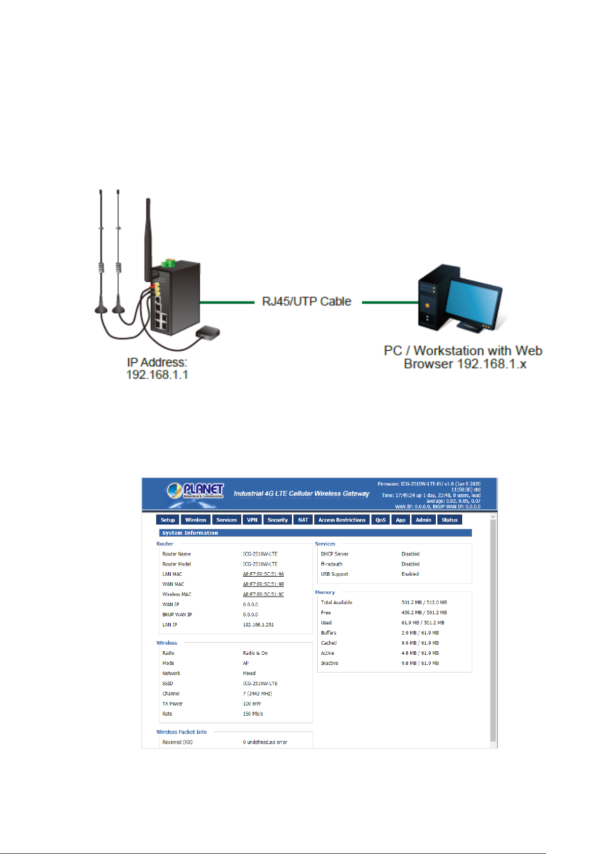
4.1. Configura t ion Connection
Before configuration, you should connect the cellular gateway and your configuration PC with the supplied network
cable. Plug the cable’s o ne end into t he Loc al Netw ork port o f the cellul ar gatew ay, and another end into your configure
PC’s Ethernet port. The connection diagram is as follows:
Please modify the IP address of PC to the same network segment address of the router, for instance, 192.168.1.9.
Modify the mask code of PC to 255.255.255.0 and set the default gateway of PC as the router’s IP address
(192.168.1.1).
4.2. Accessing the Confi guration Web Page
The chapter is to present main functions of eac h page. Users visit page tool via web browser after connecting user PC
to the cellular gateway. There are eleven main pages: Setting, Wireless, Service, VPN, Security, Access Restrictions,
NAT, QoS Setting, Applications, Management and Status. Users enable to browse slave pages by clicking one main
page.
Users can open IE or others and enter the cellular gateway's default IP address of 192.168.1.1 on address bar, then
click on “Enter” to go to the Web management tool of the cellular gateway. Log in to the web page with the first user
name, and it will display a page asking you to modify the default user name and password of the cellular gateway.
Users have to click "change password" to make it work if they want to modify user name and password.
31
Page 32

The information main page is shown below.
Users need to input user name and password if it is their first time to log in.
Input correct user name and password to visit relevant menu page. Default user name and pas sw or d are admin.
32
Page 33

4.3. Management and Configuration
The Industrial Cellular Gateway offers management features that allow users to manage the Industrial Cellular
Gateway from anywhere on the network through a standard browser such as Microsoft Internet Explorer. After you set
up your IP address for the cellular gateway, yo u can access the Industrial Cellular Gateway's Web interface
applications directly in your Web browser by entering the IP address of the Industrial Cellular Gateway.
4.3.1. Setting
The Setup screen is the first screen users will see when access ing the cel lul ar gateway. Most users will be able to
configure the gateway and get it work properly using only the settings on this screen. Some Internet Service Providers
(ISPs) will require users to enter specific information, such as User Name, Password, IP Address, Default Gateway
Address, or DNS IP Address. This information can be obtained from your ISP, if required.
4.3.1.1. Basic Setting
WAN Connection Type
The connection types include Disabled, Static IP, Automatic Configuration-DHCP, dhcp-4G, PPPoE, 3G Link1, 3G
Link2 and dhcp-bkup4G.
Disabled
Forbid the setting of WAN port connection type.
Static IP
33
Page 34

Object – Static IP Description
WAN IP Address Users set IP address by their own or ISP assigns
Subnet Mask Users set subnet mask by their own or ISP assigns
Gateway Users set gateway by their own or ISP assigns
Static DNS1/DNS2/
Users set static DNS by their own or ISP assigns
DNS3
Automatic Configuration-DHCP
IP address of WAN port gets automatic via DHCP.
DHCP-4G
IP address of WAN port gets automatic via DHCP-4G
34
Page 35

Object –
dhcp-4G
User Name Login user’s ISP (Internet Service Provider)
Password Login user’s ISP
APN Access point name of user’s ISP
PIN PIN code of user’s SIM card
Description
35
Page 36

PPPoE
Object – PPPoE Description
User Name Login the Internet
Password Login the Internet
36
Page 37

3G Link1
Object – 3G
Link1
User Name Login user’s ISP (Internet Service Provider)
Password Login user’s ISP
Dial String Dial number of user’s ISP
APN Access point name of user’s ISP
PIN PIN code of user’s SIM card
Description
37
Page 38

3G Link2
Object – 3G
Link2
User Name Login user’s ISP (Internet Service Provider)
Password Login user’s ISP
Dial String Dial number of user’s ISP
APN Access point name of user’s ISP
PIN PIN code of user’s SIM card
dhcp-bkup4G
IP address of WAN port gets automatic via DHCP-4G.
Description
38
Page 39

Object –
dhcp-bkup4G
User Name Login user’s ISP (Internet Service Provider)
Password Login user’s ISP
APN Access point name of user’s ISP
PIN PIN code of user’s SIM card
Connection Type
The connection type prov ide s 12 opt ions for required mode. This opti on a llow s u ser to se le ct c onne cti on ty pe which he
prefers, such as auto, force 3G or force 4G. The defa ult sett ing is Auto.
Description
39
Page 40

When users choose the “Route” or “Ping” method, it’s quite important to make sure that the
“Primary Detection Server IP” and “Backup Detection Server IP” are usable and stable, because
Keep Online
This function is used to detec t w het her the Int er net c onnection is active, if users set it and when the R ou ter detects the
connection is inactive, it will redial to users' ISP immediately to make the connection active. If the network is busy or
the user is in private network, we recommend that Router mode will be better.
Object – Keep
Online
Detection
Method-None
Detection
Method-Ping
Detection
Method-Route
Detection
Method-TCP
Detection
Interval
Primary
Detection Server
IP
Description
Do not set this function
Send ping packet to detect the connection, when choosing this method.
Users should also configure "Detection Interval", "Primary Detection
Server IP" and "Backup Detection Server IP" items.
Detect connection with route method, when choosing this method.
Users should also configure "Detection Interval", "Primary Detection
Server IP" and "Backup Detection Server IP" items.
Detect connection w ith T C P m ethod, when choosing this method. Users
should also configure "Detection Interval" item.
Time interval between two detections; unit is second
The server is used to response the Router’s detection packet. This item
is only valid for method "Ping" and "Route".
Backup
Detection Server
IP
they have to response the detection packet frequently.
The server is used to response the Router’s detection packet. This item
is valid for method "Ping" and "Route"
40
Page 41

Force reconnect
This option schedules the PPPoE or 3G reconnection by killing the pppd daemon and restarts it. After enabling the
function, you are able to set the time to reconnect.
STP
STP (Spanning T ree Prot oco l) can be appli ed to loop net w or k . T hrough cer t ain algorithm achieves path redundancy,
and loop network cuts to tree-based network without loop, thus avoiding the hyperplasia and infinite circulation of a
message in the loop network.
Optional Settings
Object – Keep
Online
Router Name Set Router name
Host Name ISP provides
Domain Name ISP provides
MTU
Description
auto (1500) and manual (1200-1492 in PPPOE/PPTP/L2TP mode,
576-16320 in other modes)
41
Page 42

LAN Network Setup
Object – Router
IP
Local IP Address IP address of the gateway. The default IP addre ss is 192. 16 8.1. 1
Subnet Mask The subnet mask of the gateway
Gateway
Local DNS
Network Address Server Settings (DHCP)
These settings for the gateway's Dynamic Host Configuration Protocol (DHCP) server functionality configuration. The
gateway can serve as a network DHCP server. DHCP server automatically assigns an IP address to each computer in
the network. If they choose to enable the gatewayr's DHCP server opti on, user s can set all t he comp uter s on the LAN
to automatically obtain an IP address and DNS, and make sure there are no other DHCP servers in the network.
Description
Set internal gateway of the cellular gateway. By default, internal
gateway is the address of the gateway
DNS server is auto assigned by network operator server. Users enable
to use their own DNS server or other stable DNS servers, if not, keep it
default
42
Page 43

Keep the default Enable to enable the gateway's DHCP server option. If
Object – DHCP Description
DHCP Type DHCP Server and DHCP Forwarder
DHCP Server
Start IP Address
Maximum DHCP
Users
Client Lease
Time
users already have a DHCP server on their network or users do not
want a DHCP server, then select Disable.
Enter a numerical value for the DHCP server to start with when issuing
IP addresses. Do not start with 192.168.1.1 (the gateway's own IP
address).
Enter the maximum number of PCs that users want the DHCP server to
assign IP addresses to. The absol ute maximum is 253 if 192.168.1.2 is
user’s starting IP address.
The Client Lease Time is the amount of time a network user will be
allowed to connect to the Router with their current dynamic IP address.
Enter the amount of time, in minutes, that the user will be "leased" with
this dynamic IP address.
The Domain Name System (DNS) is how the Internet translates domain
or website names into Internet addresses or URLs. Users' ISP will
Static DNS (1-3)
WINS
provide them with at least one DNS Server IP address. If users wish to
utilize another, enter that IP address in one of these fields. Users can
enter up to three DNS Server IP addresses here. The Router will utilize
them for quicker access to functioning DNS servers
The Windows Internet Naming Service (WINS) manages each PC's
interaction with the Internet. If users use a WINS server, enter that
server's IP address here. Otherwise, leave it blank.
43
Page 44

Users' domain name in the f iel d of lo cal sear ch i ncreases the expansion
DNSMasq
Time Settings
Select time zone of your location. To use local time, leave the checkmark in the box next to Use local time.
Object – Time
Settings
NTP Client DHCP Server and DHCP Forwarder
of the host option to adopt DNSMasq that can assign IP addresses and
DNS for the subnet. If select DNSMasq, dhcpd service is used for the
subnet IP address and DNS.
Description
Keep the default Enable to enable the gateway's DHCP server option. If
Time Zone
Summer Time
(DST)
Server IP/Name
Adjust Time
To adjust time by t he system and refresh to get t h e t im e o f t h e web, user can set to mod ify the time of the system. T hey
can change to adjust time by manual to achieve adjusted time by the system if the system fails to get NTP server.
users have already a DHCP server on their network or users do not
want a DHCP server, then select Disable.
Enter a numerical value for the DHCP server to start with when issuing
IP addresses. Do not start with 192.168.1.1 (the gateway's own IP
address).
IP address of NT P server is up to 32 characters. If blank, the system w ill
find a server by default.
4.3.1.2. DDNS
If user's network has a permanently assigned IP address, users can register a domain name and have that name
linked with their IP address by public Domain Name Servers (DNS). However, if their Internet account uses a
dynamically assigned IP address, users will not know in advance what their IP address will be, and the address can
change frequently. In this case, users can use a commercial dynamic DNS service, which allows them to register their
domain to their IP address, and will forward traffic directed at their domain to their frequently-changing IP address.
44
Page 45

Supports wildcard or not, the default is OFF. ON means *.host.3322.org
Object – DDNS Description
Supports PLANETDDNS, PLANET EasyDDNS, DynDNS, freedns,
DDNS Service
User Name Users register in DDNS server, up to 64 characteristic
Host Name
Type
Wildcard
Do not use
external ip check
Force Update
Interval
Status DDNS Status shows connection log information
Zoneedit, NO-IP, 3322, easyDNS, TZO, DynSIP and Custom based on
the user
Users register in DDNS server, not limited for input characteristic for
now
IP address of NTP server, up to 32 characters. If blank, the system will
find a server by default
is equal to host.3322.org
Enable or disable the function of 'do not use external ip check'
Unit is day, try forcing the update dynamic DNS to the server by setting
days
4.3.1.3. Clone MAC Address
Some ISPs need the users to regis ter their M AC address. T he users ca n clone th e gatew ay MAC address to their MAC
address registered in ISP if they do not want to re-register their MAC address. Clo ne M AC addresses can clone thr ee
parts: Clone LAN MAC, Clone WAN MAC, and Clone Wireless MAC.
45
Page 46

4.3.1.4. Advanced Routing
Operating Mode: Gateway, BGP, RIP2 Router, OSPF Router and Router
If the Router is hosting users' Internet connection, select Gateway mode. If another Router exists on their network,
select Router mode.
Dynamic Routing
Dynamic Routing enables the R outer t o au tom ati cal ly adju st t o phy sical chan ges in the network's layout and exchange
routing tables with other Routers. The Router determines the network packets’ route based on the fewest number of
hops between the source and destination.
To enable the Dynamic Routing feature for the WAN side, select WAN. To enable this feature for the LAN and wireless
side, select LAN and WLAN. To enable the feature for both the WAN and LAN, select Both. To disable the Dynamic
Routing feature for all data transmissions, keep the default setting, Disable.
Dynamic Routing is not available in Gateway mode.
46
Page 47

(internal wired and wireless networks), the WAN (Internet), or Loopback
Static Routing
Object – Static
Routing
Select set
number
Route Name Defined routing name by users, up to 25 characters
Metric 0-9999
Destination LAN
NET
Subnet Mask
Interface
Show Routing Table
Description
1-50
The Destination IP Address is the address of the network or host to
which users want to assign a static route
The Subnet Mask determines which portion of an IP address is the
network portion, and which portion is the host portion
Indicate whether the Destination IP Address is on the LAN & WLAN
(a dummy network in which one PC acts like a network, necessary for
certain software programs)
4.3.1.5. VLANS
VLANs function is to divide different VLAN ports by users' will. The system supports 15 VLAN ports from
VLAN1-VLAN15. However, there are only 5 ports (1 WAN port and 4 LAN ports) divided by users themselves, and
47
Page 48

meanwhile LAN port and WAN port disable is to divide into one VLAN port.
4.3.1.6. Networking
Object –
Description
Networking
48
Page 49

Bridging-Create
Bridge
Bridging-Assign
to Bridge
Current Bridging
Table
Create Bridge
Click 'Add' to create a new bridge; configuration is shown below:
Creates a new empty network bridge for later use. STP means
Spanning Tree Protocol and with PRIO users are able to set the bridge
priority order. The lowest number has the highest priority.
Allows users to assign any valid interface to a network bridge. Consider
setting the Wireless Interface options to Bridged if they want to assign
any Wireless Interface here. Any system specific bridge setting can be
overridden here in this field.
Shows current bridging table
Create bridge option: the first br0 means bridge name. STP means to on/ o f f spanning tree protocol. Prio me an s priority
level of STP; the small er the n umber, the higher the level. M TU means maximum tr ansfer unit; default is 1500. Delete if
it is not needed. And then click 'Save' or 'Add'. Bridge properties are shown below:
Enter relevant bridge IP address and subnet mask, and then click 'Add' to create a bridge.
Only creating a bridge can be applied.
Assign to Bridge
Assign to Bridge option: To assign different ports to created bridge. For example: assign port (wireless port) is ra0 in
br1 bridge as shown below:
49
Page 50

Prio means priority level: work if multiple ports are within the same brid ge. The smaller the number gets, t he h igh er t he
level is.
Click 'Add' to take effect.
The corresponding interfaces of WAN ports should not be bound; this bridg e func tion is basic ally
used for LAN port, and should not be bound with WAN port
If binding is successful, bridge binding list in the list of current bridging table is shown below:
To make br1 bridge have the same function with DHCP assigned address, users need to set multiple DHCP functions.
See the introduction of multi-channel DHCPD:
Port Setup
Set the port properly; the default is not set
When “Unbridged” is selected, the configuration is shown below.
50
Page 51

Object – Port
Setup-Unbridged
MTU Maximum transfer unit
Multicast
forwarding
Masquerade/NAT Enable or disable Masquerade/NAT
IP Address Set ra0's IP address, and do not conflict with other ports or bridge
Subnet Mask Set the port's subnet mask
Multiple DHCPDs
Using multiple DHCP serv ic e -- Click 'Add' in multiple DHCP servers t o appear r elevant configuration. The first means
the name of port or bridge (do not be configured as eth0), the second means whether to on DHCP. Start means start
address. Max means maximum assigned DHCP clients. Lea se time means the cl ient lease time. The unit is second.
Click 'Save' or 'Apply' to put it into effect after setting.
Description
Enable or disable multicast forwarding
Only configure and click ' Save' to configure the next; configuring multiple DHCPs at the same t ime
is not possible.
51
Page 52

4.3.2. Wireless
4.3.2.1. Basic Settings
Wireless Physical Interface
Object –
Wireless Basic
Settings
Wireless
Network
Wireless Mode AP, Client, Repeater, Repeater Bridge
Wireless
Network Mode
Wireless
Network Name
(SSID)
Wireless
Channel
Channel Width Auto, 20MHz and 40MHz
Description
Enable is for radio on and Disable is for radio off
Disabled, Mixed, BG-Mixed, B-Only, G-Only, NG-Mixed, N-Only
The default is ICG-2510W-LTE or ICG-2510WG-LTE
A total of 1-13 channels to choose from for more than one wireless
device environment. Please try to avoid using the same channel with
other devices
Wireless SSID SSID can be hidden when disabled is selected. The default is enabled.
52
Page 53

ireless
Broadcast
Network
Configuration
Virtual Interfaces
Click Add to add a virtual interface. Click on the remove to remove the virtual interface.
Object – Virtual
Server
AP Isolation
IP address needs to be manually configured w hen unbridg ed is s elected
Description
This setting isolates w irele ss cl ient so a cc es s to and f r om oth er wireless
clients are stopped.
Save your changes after changing the "Wireless Mode". For "Wireless Network Mode", "W
Width", or "Broadband" option, click on the button you prefer to configure.
4.3.2.2. Wireless Security
Wireless security op tion is used to configure the security of your wireless network. This route has a total of seven kinds
of wireless security mode. Disabled by default, not safe mode is enabled. For changes in Safe Mode, click Apply to
take effect immediately.
WEP
It is a basic encryption algor ith m that is less secure than WPA. Use o f WEP is discouraged due to security weaknesses,
and one of the WPA modes should be u sed whenever possible. Only u se WEP if you have c lient s that can only support
WEP (usually older, 802.11b-only clients).
53
Page 54

Object –
Wireless
Security-WEP
Authentication
Type
Default Transmit
Key
Encryption
ASCII/HEX
Description
Open or shared key
Select the key from Key 1 to Key 4.
There are two levels of WEP encryption, 64-bit (40-bit) and 128-bit. To
utilize WEP, select the desired encryption bit, and enter a passphra se or
WEP key in hexadecimal format. If you are using 64-bit (40-bit), then
each key must consist of exactly 10 hexadecimal characters or 5 ASCII
characters. For 128-bit, each key must consist of exactly 26
hexadecimal characters. Valid hexadecimal characters are "0"-"9" and
"A"-"F"
ASCII, the keys is 5 bit ASCII characters/13bit ASCI I characters
HEX, the keys is 10bit/26 bit hex digits
Passphrase The letters and numbers used to generate a key
Key1-Key4 Manually fill out or generated according to input on the pass phrase
54
Page 55

WPA Personal/WPA2 Personal/WPA2 Personal Mixed
Object –
Wireless
Security-WPA
Personal/WPA2
Personal/WPA2
Personal Mixed
WPA Algorithms TKIP, AES and TKIP + AES
WPA Shared Key Between 8 and 63 ASCII characters or hexadecimal digits
Key Renewal
Interval (in
seconds)
WPA Enterprise/WPA2 Enterprise/WPA2 Enterprise Mixed
Description
1-99999
Object –
Wireless
Security-WPA
Enterprise/WPA2
Enterprise/WPA2
Enterprise Mixed
WPA Algorithms TKIP, AES and TKIP + AES
Radius Auth
Server Address
Description
The IP address of the RADIUS server
55
Page 56

Radius Auth
Server Port
Radius Auth
Shared Secret
Key Renewal
Interval (in
seconds)
The RADIUS port and the default is 1812
The shared secret from the RADIUS server
1-99999
4.3.3. Services
4.3.3.1. Services
DHCP Server
DHCPd assigns IP addresses to user local devices. While the main configuration is on the setup page users can
program some nifty special functions here.
Object – DHCPd Description
Additional
DHCPd Options
Static Leases
DNSMasq
DNSmasq is a local DNS server. It will resolve all host names known to the Router from dhcp (dynamic and static) as
well as forwarding and cachin g D NS entrie s from r emot e DNS server s. Lo cal DN S enable s D HCP client s on the LAN t o
resolve static and dynamic DHCP host names.
Some extra options users can set by entering them
If users want to assign to certain hosts a specific address, they can
define them here. This is also the way to add hosts with a fixed address
to the gateway's local DNS service (DNSmasq).
56
Page 57

SNMP
Object –
DNSMasq
Local DNS
No DNS Rebind
Additional
DNSMasq
Options
Description
Enables DHCP clients on the LAN to resolve static and dy na mic DHCP
host names.
When enabled, it can prevent an external attacker to acces s the
gateway's internal Web interface. It is a secure measure.
Some extra options users can set by entering them in Additional DNS
Options.
For example:
static allocation:
dhcp-host=AB:CD:EF:11:22:33,192.168.0.10,myhost,myhost.domain,12h
max lease number: dhcp-lease-max=2
DHCP server IP range: dhcp-range=192.168.0.110,192.168.0.111,12h
Object – SNMP Description
Location
Contact
Name Some extra options users can set by entering them in Additional DNS
Enables DHCP clients on the LAN to resolve static and dy na mic DHCP
hostnames.
When enabled, it can prevent an external attacker to acces s the
gateway's internal Web interface. It is a secure measure.
57
Page 58

Options.
For example:
Static allocation:
dhcp-host=AB:CD:EF:11:22:33,192.168.0.10,myhost,myhost.domain,12h
Max lease number: dhcp-lease-max=2
DHCP server IP range: dhcp-range=192.168.0.110,192.168.0.111,12h
RO Community SNMP RO community name, the default is public, Only to read
RW Community
SSHD
Enabling SSHd allows users to access the Linux OS of their Router with an SSH client.
Object – Secure
Shell
SNMP RW community name, the default is private, Read-write
permissions
Description
SSH TCP
Enable or disable to support the TCP forwarding
Forwarding
Password Login Allows login with the gateway password (username is admin)
Port Port number for SSHd and the default is 22
Here users paste their public keys to enable key-based logi n (more
Authorized Keys
secure than a simple password)
System Log
Enable Syslogd to capture system messages. By default, they will be collected in the local file /var/log/messages. To
send them to another system, enter the IP address of a remote syslog server.
58
Page 59

a public hotspot), it is strongly
Object – System
Log
Syslog Out Mode
Remote Server
Telnet
Enable a telnet server to connect to the gateway with telnet. The username is admin and the password is the
gateway's password.
If users use the gateway in an untrusted environment (for example,
recommended to use SSHd and disable telnet.
Description
The Syslog Out Mode supports four log modes.
Net: the log information output to a syslog server
Console: the log information output to con sole port
If net mode is chosen, users should input a syslog server’s IP Address
and run a syslog server program on it
WAN Traffic Counter
Enable or disable WAN traffic counter function.
59
Page 60

4.3.4. VPN
4.3.4.1. PPTP
PPTP Server
Object – PPTP Server Description
Broadcast Support Enable or disable broadcast support of PPTP server
Force MPPE Encryption Enable of disable force MPPE encryption of PPTP data
DNS1/DNS2/WINS1/WINS-2 Set DNS1/DNS2/WINS1/WINS2
Input IP address of the gateway as PPTP server, different from LAN
Server IP
address
IP address is assigned to the client ; the format is
Client IP(s)
xxx.xxx.xxx.xxx-xxx
CHAP-Secrets User name and password of the client using PPTP service
Client IP must be different with IP assigned by gateway DHCP.
The format of CHAP Secrets is user * password *.
60
Page 61

PPTP Client
Object – PPTP
Client
Server IP or DNS
Name
Remote Subnet The network of the remote PPTP server
Remote Subnet
Mask
MPPE
Encryption
MTU Maximum transmission unit
MRU Maximum receive unit
NAT Enable or Disable network address translation
Fixed IP
User Name User name to log into PPTP Server
Password Password to log into PPTP Server
Description
PPTP server’s IP address or DNS name
Subnet mask of remote PPTP server
Enable or disable Microsoft Point-to-Point Encryption
61
Page 62

4.3.4.2. L2TP
L2TP Server
Object – L2TP
Server
Force MPPE
Encryption
Server IP
Client IP(s)
CHAP Secrets User name and password of the client using L2TP service
Description
Enable or disable force MPPE encryption of L2TP data
Input IP address of the gateway as PPTP server, different from LAN
address
IP address is assigned to the client; the format is
xxx.xxx.xxx.xxx-xxx.xxx.xxx.xxx
62
Page 63

L2TP Client
Object – L2TP
Client
User Name User name to log in L2TP server
Password Password to log in L2TP server
Gateway (L2TP
Server)
Remote Subnet The network of remote PPTP server
Remote Subnet
Mask
MPPE
Encryption
MTU Maximum transmission unit
MRU Maximum receive unit
NAT Enable or disable network address translation
Description
L2TP server’s IP Address or DNS Name
The subnet mask of remote PPTP server
Enable or disable Microsoft Point-to-Point Encryption
Require CHAP Enable or disable supporting chap authentication protocol
Refuse PAP Enable or disable refusing to support the pap authenti cat ion
Require Enable or disable supporting authentication protocol
63
Page 64

Authentication
4.3.4.3. OPENVPN
OPENVPN Server
64
Page 65

Object –
OPENVPN
Server
Start Type
Config via Server or Daemon
Server Mode Router (TUN) and Bridge (TAP) modes
Router (TUN)
Mode
Description
WAN UP: Start after online
System: Start when booting up
Network: Network address allowed by OPENVPN server
Netmask: Netmask allowed by OPENVPN server
65
Page 66

DHCP-Proxy mode: enable or disable DHCP-Proxy mode
Bridge (TAP)
Mode
Port Li s ten port of OPENVPN server
Tunnel Protocol UCP or TCP of OPENVPN tunnel protocol
Encryption
Cipher
Hash Algorithm
MRU Maximum receive unit
NAT Enable or disable network address translation
Require CHAP Enable or disable supporting chap authentication protocol
Refuse PAP Enable or disable refusing to support the pap authenti cat ion
Require
Authentication
Pool start IP: Pool start IP of the client allowed by OPENVPN server
Pool end IP: Pool end IP of the client allowed by OPENVPN server
Gateway: The gateway of the client allowed by OPENVPN server
Netmask: Netmask of the client allowed by OPENVPN server
Blowfish CBC, AES-128 CBC, AES-192 CBC, AES-256 CBC, AES-512
CBC
Hash algorithm provides a method of quick access to data, including
SHA1, SHA256, SHA512, MD4, MD5
Enable or disable supporting authentication protocol
Advanced Options
66
Page 67

OPENVPN Client
Object –
OPENVPN Client
Server IP/Name IP address or domain name of OPENVPN server
Port listen port of OPENVPN client
Tunnel Device
Tunnel Protocol UDP and TCP protocol
Encryption
Cipher
Hash Algorithm
Description
TUN: Router mode
TAP: Bridge mode
Blowfish CBC, AES-128 CBC, AES-192 CBC, AES-256 CBC, AES-512
CBC
Hash algorithm provides a method of quick access to data, including
SHA1, SHA256, SHA512, MD5
67
Page 68

Object –
OPENVPN Client
TLS Cipher
Use LZO
Compression
NAT Enable or disable NAT through function
Bridge TAP to
br0
IP Address Set IP address of local OPENVPN client
Subnet mask Set IP subnet of local OPENVPN client
Description
TLS (Transport Layer Security) encryption standard supports multiple
options
Enable or disable use LZO compression for data transfer
Enable or disable bridge TAP to br0
68
Page 69

TUN MTU Setting Set MTU value of the tunnel
TLS Auth Key Authority key of Transport Layer Security
Additional
Config
Policy based
Routing
CA Cert CA certificate
Public Client
Cert
Private Client
Key
Additional configurations of OPENVPN server
Input some defined routing policy
Client certificate
Client key
4.3.4.4. IPSEC
Connect Status and Control
Show IPSEC connection and status of current router on IPSEC page.
Object – IPSEC Description
NAME The name of IPSEC connection
Type The type and function of current IPSEC connection
Local subnet, local address, opposite end address and opposite end
Common Name
subnet of current connection
Closed: This connection does not launch a connection request to
opposite end
Negotiating: This connection launch a request to opposite end, is under
Status
negotiating, the connection has not been established yet
Establish: The connection has been est abli shed, enabled to use this
tunnel
The action of this connection, current is to delete, edit, reconnect and
enable.
Delete: To delete the connection, also will delete IPSEC if IPSEC has
Action
set up
Edit: To edit the configure information of this connection, reload this
connection to make the configuration effect after edit
69
Page 70

Reconnect: This action will remove current tunnel, and re-launch tunnel
establish request
Enable: When the connection is enable, it will launch tunnel establish
request when the system reboot or reconnect, otherwise the connection
will not do it
Add To add a new IPSEC connection
Add IPSEC connection or edit IPSEC connection
Ty pe: To choose IPSEC mode and relevant functions in this part, supports tunnel mode client, tunnel mode server and
transfer mode currently
Connection: This part contains basic address information of the tunnel
Object – IPSEC Description
NAME To indicate this connection name, must be unique
Enabled
Local WAN
Interface
Peer WAN
If enabled, the connection will send tunnel connection request when it is
reboot or re-connection, otherwise it is no need if disable
Local addresses of the tunnel
IP/domain name of end oppo si t e; thi s op tio n ca n not fill in if using tunnel
address
Local Subnet
Remote Subnet
Local ID Tunnel local end identification, IP and domain name are available
Remote ID Tunnel opposite end identification, IP and domain name are available
mode server
IPSec local protects subnet and subnet mask, i.e. 192.168.1.0/24; this
option cannot fill in if transfer mod is used.
IPSec opposite end protects subnet and subnet mask,
i.e.192.168.7.0/24; this option cannot fill in if transfer mode is used.
70
Page 71

Detection: This part contain s config ure information of connection detection
Object – IPSEC Description
Enable DPD
Detection
Time Interval Set time interval of connect detection (DPD)
Timeout Set the timeout of connect detection
Action Set the action of connect detection
Advanced Settings: This part contains relevant setting of IKE, ESP, negotiation mode, etc.
Enable or disable this function, tick means enable
Object – IPSEC Description
Enable
Advanced
Settings
IKE Encryption IKE phased encryption mode
IKE Integrity IKE phased integrity solution
IKE Grouptype DH exchange algorithm
IKE Lifetime Set IKE lifetime, current unit is hour, the default is 0
ESP Encryption ESP encryption type
ESP Integrity ESP integrity solution
Enable to configure 1st and 2nd phase information, otherwise it
will automatically negotiate according to opposite end
71
Page 72

ESP Keylife Set ESP keylife, current unit is hour, the default is 0
IKE aggressive
mode allowed
Perfect Forward
Security (PFS)
Authentication: Choose use share encryption option or certificate authentication option. Current is only to choose use
share encryption option.
Negotiation mode adopt aggressive mode if tick; it is main
mode if non-tick
Tick to enable PFS, non-tick to disable PFS
4.3.4.5. GRE
GRE (Generic Routing Encapsulation, Generic Routing Encapsulation) protocol is a network layer protocol (such as IP
and IPX). Data packets are encapsulated, so these encapsulated data packets go to another network layer protocol
(IP). GRE Tunnel technology is Layer Two Tunneling Protocol VPN (Virtual Private Network).
GRE Tunnel: Enable or disable GRE function.
When GRE tunnel is enabled, the configuration page is shown below.
72
Page 73

Object – GRE Description
Number Switch on/off GRE tunnel app
Status Switch on/off someone GRE tunnel app
Name GRE tunnel name
Through The GRE packet transmit interface
Peer Wan IP addr The remote WAN address
Peer Subnet The remote gateway local subnet, eg: 192.168.1.0/24
Peer T unnel IP The remote tunnel ip address
Local Tunnel IP The local tunnel ip address
Local Netmask Netmask of local network
Keepalive Enable or disable GRE Keepalive function
Retry times GRE keepalive detects fail retries
Interval The time interval of GRE keepalive packet sent
Fail Action The action would be exec after keeping alive failed
Users can view the information of GRE by clicking on the “View GRE tunnels” button.
73
Page 74

4.3.5. Security
4.3.5.1. Firewall
You can enable or disable the firewall, filter specific Internet data types, and prevent anonymou s Internet requests,
ultimately enhancing network security .
Firewall enhances ne tw ork security and use SP I to chec k the pac kets in the network. To use firewall protection, choose
enable otherwise disable. Only enable the SPI firewall; you can use other firewall functions: filtering proxy, block WAN
requests, etc.
Object – Security Description
WAN proxy server may reduce the security of the gateway. Filtering
Filter Proxy
Proxy will refuse any access to any WAN proxy server. Click the check
box to enable the function otherwise disabled.
Cookies are the website of data the data stored on your computer.
Filter Cookies
Filter Java
Applets
Filter ActiveX
When you interact with the site, the cookies will be used. Click the
check box to enable the function otherwise disabled.
If Java is refused, you may not be able to open web pages using the
Java programming. Click the check box to enable the function,
otherwise disabled.
If ActiveX is refused, you may not be able to open web pages using the
ActiveX programming. Click the check box to enable the function
otherwise disabled.
74
Page 75

Object – Security Description
Block
Anonymous
WAN Requests
(ping)
Filter IDENT
(Port 113)
Block WAN
SNMP access
By selecting “Block Anonymous WAN Requests (ping)” box to enable
this feature, you can prevent your network from the Ping or detection of
other Internet users. The default state of this feature is enabled. When
disable is selected, it allows anonymous Internet requests.
Enable this feature can prevent port 113 from being scanned from
outside. Click the check box to enable the function otherwise disabled.
This feature prevents the SNMP connection requests from the WAN.
Object – Security Description
Limit SSH
Access
Limit Telnet
Access
Limit PPTP
Server Access
Limit L2TP
Server Access
This feature limits the access request from the WAN by SSH, and per
minute up to accept two connection requests on the same IP. Any new
access request will be automatically dropped.
This feature limits the access request from the WAN by Telnet, and per
minute up to accept two connection requests on the same IP. Any new
access request will be automatically dropped.
When build a PPTP Ser v er in the Router, this feature limits the access
request from the WAN by SSH, and per minute up to accept two
connection requests on the same IP. Any new access request will be
automatically dropped.
When building a L2TP Server in the Router, this feature limits the
access request from the WAN by SSH. It accepts up to two connection
requests per minute on the same IP. Any new access request will be
75
Page 76

automatically dropped.
Log Management
The gateway can keep logs of all incoming or outgoing traffic for your Internet connection.
Object – Log
Management
Log
Description
To keep activity logs, select Enable. To stop logging, select Disable.
When selecting enable, the following page will appear.
76
Page 77

To see a temporary log of the Rout er' s most r e cen t outg oing traffic, click
Log Level
Options
Incoming Log
Outgoing Log
Set this to the required log level. Set Log Level higher to log more
actions.
When selecting Enable, the corresponding connection will be recor ded
in the journal; disable is not recorded.
To see a temporary log of the R outer's m ost recen t incom ing traffic, click
the Incoming Log button.
the Outgoing Log button.
4.3.6. Access Restrictions
4.3.6.1. WAN A ccess
You can block or allow specific types of Internet applications f or WAN access restrictions. You can set specific
PC-based Internet access policies. This feature allows you to customize up to 10 different Internet Access Policies for
particular PCs, which are identified by their IP or MAC addresses.
Two options in the default policy rules: "Filter" and "reject". If selecting "Deny”, you will deny specific computers to
access any Internet service at a particular time period. If you choose "filter", It will block specific computers to access
the specific sites at a specific time period. You can set up 10 Internet access policies filtering specific PCs access
Internet services at a particular time period.
77
Page 78

Object – WAN
Access
Access Policy
Status Enable or disable a policy.
Policy Name You may assign a name to your policy.
PCs
Days Choose the day of the week to have your policy applied.
Times Enter the time of the day to have your policy applied.
Website
Blocking by URL
Description
You may define up to 10 access policies. Click Delete to delete a policy
or Summary to see a summary of the policy.
The part is used t o edit client list; the str ategy is only effective for the PC
in the list.
You can block access to certain websites by entering their URL.
78
Page 79

Address
Website
Blocking by
Keyword
You can block access to certain website by the keywords contained in
their webpage
The steps of setting up Internet access policy
1. Select the policy number (1-10) in the drop-down menu.
2. For this policy to be enabled, click the radio button next to "Enable"
3. Enter a name in the Policy Name field.
4. Click the Edit List of PCs button.
5. On the list of PC screen, specify PCs by IP address or MAC address. Enter t he appro pr ia te I P ad dr es se s i nto t he I P
fields. If you have a range of IP addresses to filter and complete the appropriate IP Range fields. Enter the appropriate
MAC addresses into the MAC fields.
6. Click the Apply button to save your changes. Click the Cancel button to cancel your unsaved changes. Click the
Close button to return to the Filters screen.
7. If you want to block the listed PCs from Internet access during the designated days and time, then keep the default
79
Page 80

After
automatically synchronized, you need to
setting, Deny. If you want the listed PCs to have Internet filtered during the designated days and time, then click the
radio button next to Filter.
8. Set the days when access will be filtered. Select Everyday or the appropriate days of the week.
9. Set the time when access will be filtered. Select 24 Hours, or check the box next to From and use the drop-down
boxes to designate a specific time period.
10. Click the Add to Policy button to save your changes and activate it.
11. To create or edit additional policies, repeat steps 1 to 9.
12. To delete an Internet Access Policy, select the policy number, and click the Delete button.
The default factory value of policy rules is "f iltered". If the user chooses t he default policy rules for
"refuse", editing strategies to directly save the settings. If the strategy edited is the first, it will be
automatically saved into the second, if not, the first to keep the original number.
Turning off the power of the Router or rebooting the Router can cause a temporary failure。
the failure of the Router, if NTP timer server cannot be
recalibrate to ensure the correct implementation of the relevant period control function.
4.3.6.2. URL Filter
If you want to prevent certain client access to specific network domain name, such as www.yahoo.com.tw., achieve it
through the function of URL filtering.
Object – URL
Filter
Discard packets
that conform to
the following
Description
Only discard the matching URL address in the list.
80
Page 81

rules
Accept only the
data packets that
conform to the
following rules
MAC Filter
Receive only custom rules of network address; discard all other URL
addresses.
Object –MAC
Filter
Discard packets
conform to the
following rules
Accept only the
data packets
conform to the
following rules
Description
Only discard the matching MAC address in the list.
Receive only custom rules of MAC address; discard all other MAC
addresses.
4.3.6.3. Packet Filter
To block some packets getting Internet access or block some Internet packets getting local network access, you can
configure filter items to block these packets. Packet filter function is realized based on IP address or port of packets.
81
Page 82

Object –Packet
Filter
Enable Packet
Filter
Policy
Add Filter Rule
Direction
Protocol Packet protocol type
Source Ports Packet’s source por t
Destination
Ports
Source IP Packet’s source IP address
Destination IP Packet’s destination IP address
Description
Enable or disable “packet filter” function
Two policies are provided. One is Discard packets conform to the
following rules and the other is Accept only the data packets conform to
the following rules.
Input: packet from WAN to LAN
Output: packet from LAN to WAN
Packet’s destination port
4.3.7. NAT
"Source Port”,” Destination Port" ,"Source IP" ,"Destination IP" could not be all empty.
82
Page 83

number of the external port (the port nu mber seen by users on
4.3.7.1. Port Forwarding
Port Forwarding allow s y ou to set up public services on your network, such as web servers, ftp servers, e-m ail server s,
or other specialized Internet applications. Specialized Internet applications are any applications that use Internet
access to perform fun ctio ns su ch a s v id eoc onferencing or online gaming. When users send this type of request to your
network via the Internet, the Router will forward those requests to the appropriate PC. If you want to forward a whole
range of ports, see Port Range Forwarding.
Object –Port
Forward
Application Enter the name of the application in the field provided.
Protocol
Source Net Forward only if sender matches this ip/net (example 192.168.1.0/24).
Port from
IP Address Enter the IP Address of the PC running the application.
Port to
Enable Click the Enable checkbox to enable port forwarding for the application.
Description
Chose the right protocol TCP, UDP or Both. Set this to what the
application requires.
Enter the
the Internet).
Enter the number of the internal port (the port number used by the
application).
4.3.7.2. Port Range Forward
Port Range Forwarding allows you to set up public services on your network, such as web servers, ftp servers, e-mail
servers, or other specialized Inter net app lic atio ns. Spe cialized Internet applications are any applications that use
Internet access to perform functions such as videoconferencing or online gaming. When users send this type of
request to your network via the Internet, the Router will forward those requests to the appropriate PC. If you only want
to forward a single port, see Port Forwarding.
83
Page 84

Object –Port
Range Forward
Application Enter the name of the application in the field provided.
Start
End
Protocol
IP Address Enter the IP Address of the PC running the application.
Enable Click the Enable checkbox to enable port forwarding for the application.
Description
Enter the number of the first port of the range you want to be seen by
users on the Internet and forwarded to your PC.
Enter the number of the last port of the range you want to be seen by
users on the Internet and forwarded to your PC.
Chose the right protocol TCP, UDP or Both. Set this to what the
application requires.
4.3.7.3. DMZ
The DMZ (DeMilitarized Zone) hosting feature allows one local user to be exposed to the Internet for use of a
special-purpose service such as Internet gaming or video co nf eren cin g. D MZ hosting forwards all the ports at the sa me
time to one PC. The Port Forwarding feature is more secure beca use it on ly open s the por t s y ou w ant to have opened,
while DMZ hosting opens all the ports of one computer, exposing the computer so the Internet can see it.
Any PC whose port is being forwarded must have a new static IP address assigned to it because its IP address may
change when using the DHCP function.
DMZ Host IP Address: To expose one PC to the Internet, select Enable and enter the computer's IP address in the
DMZ Host IP Address field. To disable the DMZ, keep the default setting: Disable
84
Page 85

4.3.8. QoS Setti n g
4.3.8.1. Basic
Bandwidth management priorit izes the traffic on your Router. Interactive traffic (telephony, browsing, telnet, etc.) gets
priority and bulk traffic (file transfer, P2P) gets low priority. The main goal is to allow both types to work side-by-side
leaving out unimportant traffic. All of this is more or less automatic.
Object –QoS Description
In order to use bandwidth management (QoS) you must enter
Uplink (kbps)
Downlink (kbps )
bandwidth values for your uplink. These are generally 80% to 90% of
your maximum bandwidth.
In order to use bandwidth management (QoS) you must enter
bandwidth values for your dow nlin k. T hese are generally 80% to 90% of
your maximum bandwidth.
4.3.8.2. Classification
The classification part includes netmask priority and MAC priority. You are able to specify priority for all traffic from a
given IP address, port range or M A C addr ess. C h ec k al l v alu es an d cl ic k Sav e Set ti ngs t o s av e y our setti ngs. C lick the
Cancel changes button to cancel your unsaved changes.
85
Page 86

4.3.9. Applications
4.3.9.1. Serial Applications
There is a console port on Router. Normally, this port is used to debug the Router. This port can also be used as a
serial port. The Router has embedded a serial to TCP program. The data sent to the serial port is encapsulated by
TCP/IP protocol st ac k and t he n is s ent to the destination server. This function can work as a DTU (Data Terminal Unit).
86
Page 87

The time interval to send heart beat packet. This item is valid only when
Object –Serial
Applications
Baudrate
Databit
Stopbit It marks the end of a character data. It is a high level of 1, 1.5, and 2.
Parity Use a set of data to check the data error.
Flow control Including the hardware part and software part in two ways.
Protocol
Description
Baud rate indicates the number of bytes per second transported by
device, commonly used baud rate is115200, 57600, 38400, and 19200.
The data bits can be 4, 5, 6, 7, 8, consti tute a charact er. The ASCII code
is usually used. Starting from the most significant bit is transmitted.
The protocol type for transmitting data.
UDP (DTU): Data transmission in UD P protocol works as an IP MODEM
device which has application protocol.
Pure UDP: Data transmission in standard UDP protocol.
TCP (DTU): Data transmission with TCP protocol works as an IP
MODEM device which has application protocol.
Pure TCP: Data transmission in standard TCP protocol, Router is the
client.
TCP Server: Data transmission in standard TCP protocol, Router is the
server.
TCST: Data tra nsmission in TCP protocol that uses a custom data
Server Address The data service center’s IP Address or domain name.
Server Port The data service center’s listening port.
Device ID The Router’s identity ID.
Device Number The Router’s phone number.
Heartbeat
Interval
TCP Server
Listen Port
Custom
Heartbeat Packet
Custom
Registration
you choose UDP (DTU) or TCP (DTU) protocol type.
This item is valid when Protocol Type is “TCP Server”.
This item is valid when Protocol Type is “TCST”.
This item is valid when Protocol Type is “TCST”.
Packet
4.3.10. Admin
87
Page 88

username is admin. It is strongly recommended that you change the factory default
4.3.10.1. Management
The Management screen allow s you to change the Router's settings. On this page you will find most of the
configurable items of the Router code.
The new password must not ex ceed 32 chara cters in le ngth and must not i nclude a ny spaces. E nter th e new passw ord
twice to confirm it.
Default
password of the Router, which is admin.
Web Access
This feature allows you to manage the Router using either HTTP protocol or the HTTPS protocol. If you choose to
disable this feature, a manual reboot will be required. You can also activate or inactivate the Router information web
page. It's now possible to have a password to protect this page (same username and password as the above).
Object –Web
Access
Protocol
Auto-Refresh (in
seconds)
Enable Info Site Enable or disable the login sys tem information page.
Description
This feature allows you to manage the Router using either HTTP
protocol or the HTTPS protocol.
Adjust the Web GUI automatic refresh interval. 0 disables this feature
completely.
88
Page 89

Info Site
Password
Protection
Remote Access
This feature allows you to manage the Router from a remote location via the Internet. To disable this feature, keep the
default setting, Disab le. To enable this feature, sele ct Enable , and use th e spec ified por t (def ault is 8 080) o n your PC to
remotely manage the Router. You must also change the Router's default password to one of your own, if you haven't
already.
To remotely manage the Router, enter http://xxx.xxx.xxx.xxx:8080 (the x's represent the Router's Internet IP address,
and 8080 represents the specified port) in your web browser's address field. You will be asked for the Router's
password.
If you use https you need to specify the url as https://xxx.xxx.xxx.xxx:8080 (not all firmwares do support this without
rebuilding with SSL support).
Enable or disable the password protection feature of the system
information page.
Object –Remote
Access
SSH
Management
Telnet
Management
Cron
The cron subsystem sche dule s ex ecution of Lin ux commands. You'll need to use the comm and line or star tup s cripts to
actually use this.
Description
You can also enable SSH to remotely access the Router by Secure
Shell. Note that SSH daemon needs to be enabled in Services page.
Enable or disable remote Telnet function.
89
Page 90

Remote Management
Firmware Upgrade
Choose Enable to have a firmware upgrade.
4.3.10.2. Keep Alive
User is able to reboot the device automatically by interval or specific time.
90
Page 91

4.3.10.3. Commands
The function allows you to run command line directly via the Web interface.
Object –
Commands
Run Commands
Save Startup
Save Shutdown
Save Firewall
Save Custom
Script
Description
You can run command lines via the web interface. Fill the text area with
your command and click Run Commands to submit.
You can save some command lines to be executed at startup's Router.
Fill out the text area with commands (only one command by row) and
click Save Startup.
You can save some command lines to be executed at shutdown's
Router. Fil l out the text area with commands (only one command by
row) and click Save Shutdown.
Each time the firewall is started, it can run some custom ip tables
instructions. Fill out the text area with firewall's instructions (only one
command by row) and click Save Firewall.
Custom script i s stored i n /tm p/cust om.sh f ile. You can run it manually or
use cron to call it. Fill out the text ar ea with script' s instru ction s (only on e
command by row) and click Save Custom Script.
4.3.10.4. Factory Defaults
Select the “Yes” button to reset all configuration settings to their default values then click the A pply Settings button to
take effect.
91
Page 92

Any settings you have saved will be lost when the default settings are restored. The
default IP address is 192.168.1.1 and the default password is admin.
4.3.10.5. Firmware Upgrade
4.3.10.6. Backup
Object –Backup Description
Backup Settings
You may back up your current configuration in case you need to reset
the Router back to its factory default sett ing s. Cli ck the Backup button to
92
Page 93

back up your current configura tion.
Click the “Browse...” button to browse for a configuration file that is
Restore Settings
currently saved on your PC. Click the Restore button to overwrite all
current configurations with the ones in the configuration file.
4.3.11. Status
The Status function provides different system and real-time information such as Router, WAN, Backup WAN, LAN,
Wireless, Bandwidth and Sys-Info. It can help the user to monitor the current state of the machine at any time.
93
Page 94

5. APPENDIX A RJ45 Pin Assignments
5.1. A.1 10/100/1000Mbps, 10/100/1000BASE-T
When connecting your 10/100/1000Mbps Cellular Gateway to another device, a bridge or a hub, a straight-through or
crossover cable is necessary. Each port of the Cellular Gateway supports auto-MDI/MDI-X detection. That means you
can directly connect the Cellular Gateway to any Ethernet devices without making a crossover cable. The following
table and diagram show the standard RJ45 receptacle/connector and their pin assignments:
RJ45 Connector pin assignment
Contact MDI
Media Dependent
1 Tx + (transmit) Rx + (receive)
2 Tx - (transmit) Rx - (receive)
3 Rx + (receive) Tx + (transmit)
4, 5 Not used
6 Rx - (receive) Tx - (transmit)
7, 8 Not used
The standard cable, RJ45 pin assignment
Interface
MDI-X
Media Dependent
Interface-Cross
The standard RJ45 receptacle/connector
There are 8 wires on a standard UTP/STP cable and each wire is color-coded. The following shows the pin allocation
and color of straight-through c able and cro ssover cab le con n ecti on:
94
Page 95

1 2 3 4 5 6 7 8
1 2 3 4 5 6 7 8
1 2 3 4 5 6 7 8
1 2 3 4 5 6 7 8
Straight-through Cable SIDE 1 SIDE 2
SIDE 1 1 = White /
Orange
2 = Orange
3 = White /
Green
4 = Blue
SIDE 2
Crossover Cable SIDE 1 SIDE 2
SIDE 1 1 = White /
5 = White /
Blue
6 = Green
7 = White /
Brown
8 = Brown
Orange
2 = Orange
3 = White /
1 = White /
Orange
2 = Orange
3 = White /
Green
4 = Blue
5 = White /
Blue
6 = Green
7 = White /
Brown
8 = Brown
1 = White /
Green
2 = Green
3 = White /
Green
4 = Blue
SIDE 2
Figure A-1: Straight-through and Crossover Cables
Please make sure your connected cables are with the same pin assignment and color as the above table before
deploying the cables into your network.
5 = White /
Blue
6 = Green
7 = White /
Brown
8 = Brown
Orange
4 = Blue
5 = White /
Blue
6 = Orange
7 = White /
Brown
8 = Brown
95
 Loading...