

Page 1

User’s Manual
ICA-HM830W
2 Mega-Pixel Wireless Fisheye
IP Camera
Page 2

Copyright
Copyright © 2011 by PLANET Technology Corp. All rights reserved. No part of this publication
may be reproduced, transmitted, transcribed, stored in a retrieval system, or translated into any
language or computer language, in any form or by any means, electronic, mechanical, magnetic,
optical, chemical, manual or otherwise, without the prior written permission of PLANET.
PLANET makes no rep resentations or warranties, either expressed or implied, with respect to
the contents hereof and specifically disclaims any warranties, merchantability or fitness for any
particular purpose. Any software described in this manual is sold or licensed "as is". Should the
programs prove defective following their purchase, the buyer (and not PLANET, its distributor, or
its dealer) assumes the entire cost of all ne cessary servicing, repair, and any incidental or
consequential damages resulting from any defect in the software. Further, PLANET reserves the
right to revise this publica tion and to make changes from time to time in the contents hereof
without obligation to notify any person of such revision or changes.
All brand an d product names mentioned in this manual a re trademarks and/or
registered trademarks of their respective holders.
Federal Communication Commission Interference St atement
This equipment has been tested and found to comply with the limits for a Class B digital device,
pursuant to Part 15 of FCC Rul es. These limits are designed to provide reasonable protection
against harmful interference in a residential installation. This equipment generates, uses, and
can radiate radio freq uency energy and, if not in stalled and used in acco rdance with the
instructions, may cause harmful interference to radio communications. However, there is no
guarantee that interference will not occur in a particular installation. If this equipment does cause
harmful interference to radio or tel evision reception, which can b e determined by turning t he
equipment off and on, the user is encouraged to try to correct the interference by one or more of
the following measures:
1. Reorient or relocate the receiving antenna.
2. Increase the separation between the equipment and receiver.
3. Connect the equipment into an outlet on a circuit different from that to which the receiver is
connected.
4. Consult the dealer or an experienced radio technician for help.
FCC Caution
To assure continued compliance. (example-use only shielded interface cables when connecting
to computer or peripheral devices). Any changes or modifications not expressly approved by the
party responsible for compliance could void the user’s authority to operate the equipment.
This device complies with Part 15 of the FCC Rules. Operation is subj ect to the Following two
conditions: ( 1 ) This device may not cause harmful interference, and ( 2 ) this Device must
accept any interference received, including interference that may cause undesired operation.
Federal Communication Commission (FCC) Radiation Exposure Statement
This equipment complies with FCC radiation exposure set forth for an uncontrolled environment.
In order to avoid the possi bility of exceeding t he FCC radio frequency exposure limits, human
proximity to the antenna shall not be less than 20 cm (8 inches) during normal operation.
Page 3

Safety
This equipment is designed with the utmost care for the safety of those who install and use it.
However, special attention must be p aid to the dangers of electric sho ck and static electricity
when working with electrical equipment. All guidelines of this and of the computer manufacture
must therefore be allowed at all times to ensure the safe use of the equipment
.
CE Mark Warning
This is a Class B product. In a domestic environment, this product may cause radio interference,
in which case the user may be required to take adequate measures.
WEEE Regulation
To avoid the potential effects on the environment and human health as a result of the
presence of hazardous substances in electrical and electronic equipment, end users
of electrical and electronic equipment should understand the meaning of the
crossed-out wheeled bin symbol. Do not di spose of WEEE as unsorted municipal
waste and have to collect such WEEE separately.
Revision
User’s Manual for PLANET 2 Mega-Pixel Wireless Fisheye IP Camera
Model: ICA-HM830W
Rev: 1.0 (October. 2011)
Part No. EM-ICA-HM830W
Page 4

Table of Content
U1.U UIntroductionU ............................................................................................................... 6
U1.1U UOverviewU ............................................................................................................ 6
U1.2 FeaturesU.............................................................................................................. 6
U1.3U UPackage ContentsU ............................................................................................ 7
U2.U UBasic SetupU............................................................................................................... 8
U2.1U USystem RequirementU........................................................................................ 8
U2.2U UPhysical DescriptionU ......................................................................................... 9
U2.2.1 Identification of ICA-HM830W physical detailU ................................... 9
U2.3U UHardware InstallationU ..................................................................................... 12
U2.3.1 Physical InstallationU ............................................................................. 12
U2.3.2 Wall/Ceiling Mount Installation ProcedureU ....................................... 13
U2.4U UInitial Utility InstallationU .................................................................................. 14
U2.5U UPreparationU ......................................................................................................14
U2.5.1 Configure Network by PLANET IPInstallerU ...................................... 14
U2.5.2 Open the Web-based UI of the select cameraU................................ 16
U2.6U USetup ActiveX to use the Internet CameraU ................................................. 17
U2.6.1 Internet Explorer 6 for Windows XPU.................................................. 17
U2.6.2 Internet Explorer 7 for Windows XPU.................................................. 18
U2.6.3 Internet Explorer 7 for Windows VistaU .............................................. 19
U2.7U UUsing UPnP of Windows XP or VistaU .......................................................... 20
U2.7.1 Windows XPU ......................................................................................... 20
U2.7.2 Windows VistaU ...................................................................................... 24
U3.U UWeb-based ManagementU ..................................................................................... 25
U3.1 IntroductionU ...................................................................................................... 25
U3.2 Connecting to Internet CameraU..................................................................... 25
U3.3 Live ViewU .......................................................................................................... 28
U3.4 Video ConfigurationU ........................................................................................ 30
U3.4.1 Video General SettingsU ....................................................................... 30
U3.4.2 Video Advanced SettingsU.................................................................... 32
U3.4.3 External Video SourceU ........................................................................ 33
U3.5 Camera ConfigurationU ....................................................................................34
U3.5.1 Camera General SettingsU ................................................................... 34
U3.5.2 Camera Advanced SettingsU................................................................ 36
U3.6 Event ConfigurationU ........................................................................................ 39
U3.6.1 Event ServerU ......................................................................................... 39
U3.6.1.1 FTP serverU ......................................................................................... 39
U3.6.1.2 Event Server RemoveU...................................................................... 40
U3.6.2 Motion DetectionU .................................................................................. 41
U3.6.3 I/O PortsU ................................................................................................ 43
U3.6.4 Event ConfigurationU ............................................................................. 44
U3.7 Schedule ConfigurationU .................................................................................. 46
U3.7.1 General SettingU .................................................................................... 46
U3.7.2 Storage SettingU..................................................................................... 47
U3.8 Network ConfigurationU .................................................................................... 48
U3.8.1 Network General SettingsU .................................................................. 48
Page 5

U3.8.2 Network Advanced SettingsU ............................................................... 49
U3.8.3 Network SMTP SettingsU...................................................................... 51
U3.8.4 DDNS serverU ........................................................................................ 52
U3.8.5 WirelessU................................................................................................. 53
U3.9 System MaintainU .............................................................................................. 55
U3.9.1 System InformationU.............................................................................. 55
U3.9.2 User Account ConfigurationU ............................................................... 56
U3.9.3 Date & Time ConfigurationU ................................................................. 57
U3.9.4 Server MaintenanceU ............................................................................ 58
U3.9.5 Log ServiceU ........................................................................................... 60
U3.10 CustomizeU ......................................................................................................60
U3.10.1 Use Default LookU ............................................................................... 60
U3.10.2 Use Custom SettingsU ........................................................................ 61
UAppendix A: Reset Factory Default SettingsU ............................................................. 63
UAppendix B: PING IP AddressU ..................................................................................... 64
UAppendix C: Bandwidth and Video Size EstimationU................................................. 65
UAppendix D: DDNS ApplicationU ................................................................................... 66
UAppendix E: Configure Port Forwarding ManuallyU ................................................... 71
UAppendix F: Troubleshooting & Frequently Asked QuestionsU ................................74
UAppendix G: Product SpecificationU.............................................................................. 78
Page 6

1. 0BIntroduction
PLANET ICA-HM830W is the new H.264 2Mega-Pixel Fixed Dome IP camera featuri ng a fish-eye lens for
360 degree panoramic wide angle view without blind spot. The ICA-HM830W delivers clear image through
Multi-streaming H.264 an d Motion JPEG video up to UXGA (160 0 x 1200 pixels). The fish-eye lens with
2Mega Pixel high resolution images provides 360 degree wide view surveillance and the panorama function
with quad view enables four different angles images to display simultaneously for monitoring and recording.
The ICA-HM830W digital Pan/Tilt and zoom function can provide users 9 different video modes including:
D 360° Source image
D 360°Table view
D 180° double broad view
D 180° double table broad view
D 360° source view with 3 PTZ
Furthermore, the ICA-HM8 30W applies perspective correction software to eliminate the rounding normally
associated with fisheye lenses and thus save lots of traditional mechanical Pan/Tilt maintenance cost.
The ICA-HM830W is highl y flexible to be a pplied in various kinds of IP surveil lance environment. It has
built-in ICR (IR -cut filter Rem ovable) for day / night surveillance and is c ompatible with IEEE 802.11 b/g/n
wireless technology and WEP / W PA encryptions. In addition, the IC A-HM830W provides surveillance
functions including DI/DO al arm, Micro SD card sup port for local stor age, and 2-Way audio that en ables
audio communication between local and remote ICA-HM830W installed sites by connecting the e xternal
microphone and speaker.
D Quad view
D 360° broad view with 2 PTZ
D 180° source view with 3 PTZ
D 180° broad view with 2 PTZ
The ICA-HM830W is the pe rfect panoramic surveillance application for the hall way, stores or offices so
customers do not need to install multiple IP cameras and thus can save l ots of installation and maintenance
cost. More over, the ICA-HM830W can be manag ed by PLANET Cam Vie wer 3 IP-Surveill ance
management software for multi-camera video surveillance application and provides monitoring, recording and
event management functions to secure your property and life.
1.1 10BOverview
This user’s guide explains how to operate this cam era from a compute r. User should read this
manual completely and carefully before you operate the internet camera.
11B1.2 Features
• 360 degree Fish-Eye panoramic wide angle view
• 9 different 360 degree/ 180 degree video mode including digital PTZ function
• High quality 2Mega-Pixel CMOS image sensor (maximum up to 1600 x 1200 resolution)
• H.264 and M-JPEG dual codec
• Day/Night switch with ICR (IR-cut Filter Removable)
• IEEE 802.11b/g/n wireless LAN with WEP and WPA encryption
• 2-Way audio with built-in microphone and speaker
• 10 motion detection areas / E-mail and FTP alert
• External I/O trigger for various surveillance application
• High performance video decoder to decrease image distortion
• DDNS and FTP uploading provide more alternatives in surveillance network
Page 7

1.3 12BPackage Contents
IP Camera unit x 1
Power Adapter x 1
Quick Installation Guide x 1
User’s Manual CD x 1
Wall Mount Kit x 1
GPIO Connector x 1
1. If any of the above items are missing, please contact your dealer immediately.
NOTE:
2. Using the power supply that is not the one included in Internet camera packet wil l
cause damage and void the warranty for this product.
Page 8

2. 1BBasic Setup
This chapter provides details of installing and configuring the Internet camera
2.1 13BSystem Requirement
The Internet Camera can be monitoring on all of Windows operating system that sugg est with
system requirment below in or der to got better video pe rformance when resolution up to 2
megapixel.
NOTE:
CPU
RAM
Video RAM
Display Chip
Display Resolution
Operating System
DirectX
Network
1. The listed information is minimum system requirements only . Actual requirem ent
will vary depending on the nature of your environment.
2. The ICA-HM830W can be managed by PLANET Cam Viewer Three if you want
to configure more detail information and settings of camera viewer plus soft ware
please refer to the CD-ROM folder “D:\Manual\Cam Viewer 3\”, ass ume D is
your CD-ROM drive.
Intel® Core2 Duo E3500 2.7GHz
2 GB
128MB
nVIDIA GeForce 8500GT or ATI Radeon HD 4350 or above
1024 x 768 24bits
Windows 2000 SP4 / Windows XP Pro SP2 / Windows 2003 / Vista/
Windows 7
9.0c or above
Wired Ethernet 100Base-TX
Page 9
2.2 14BPhysical Description
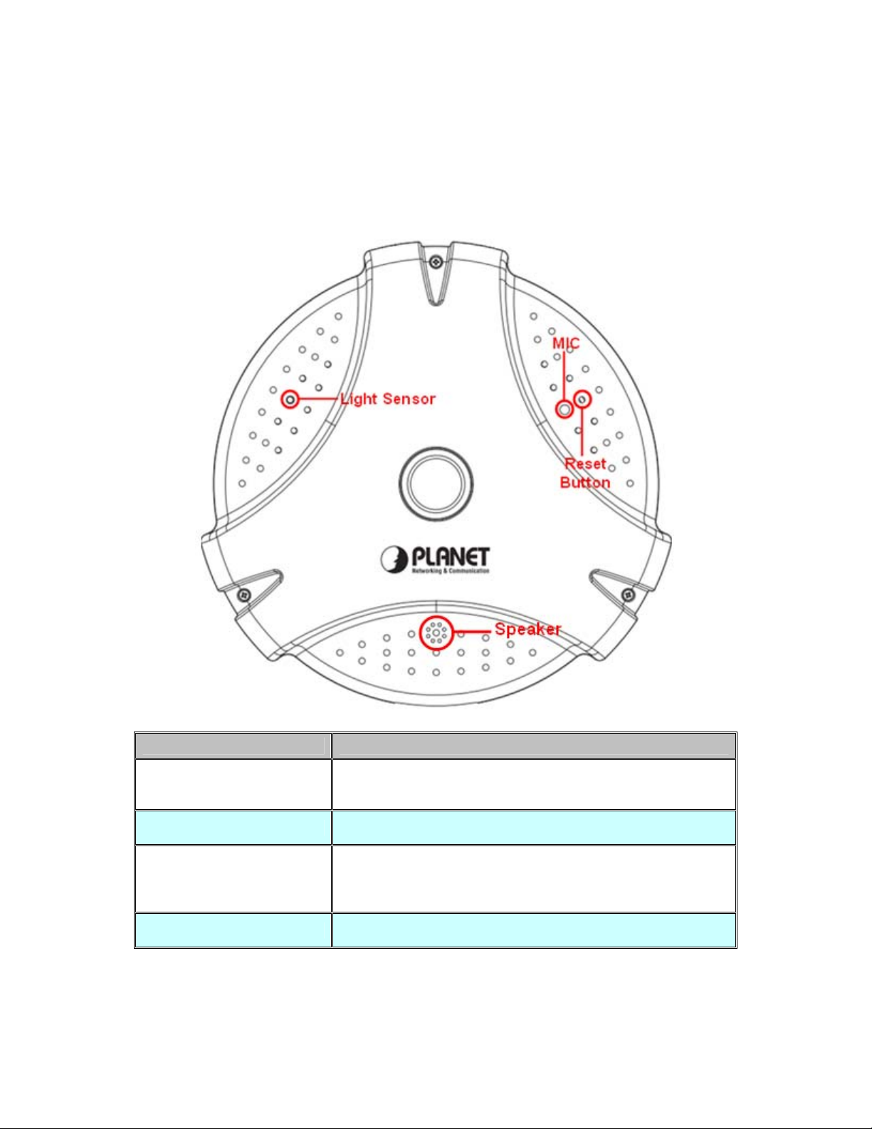
30B2.2.1 Identification of ICA-HM830W physical detail
Font view
Interface Description
The Light sensor is for detect IP Camera environment
Light Sensor
MIC
Reset Button
Speaker
illuminant, and if IP Camera in the dark/night environment that
will let IR cut filter off for clearly night view.
The IP Camera has built-in an internal microphone. This
microphone is hidden in the pinhole located on the front panel.
This button is hidden in the pinhole. This button is used to
restore the all factory default settings. Sometimes restarting
the Internet Camera will make the system back to a normal
state.
The IP Camera has built-in an internal speaker. This speaker
is hidden in the pinhole located on the front panel.
Page 10
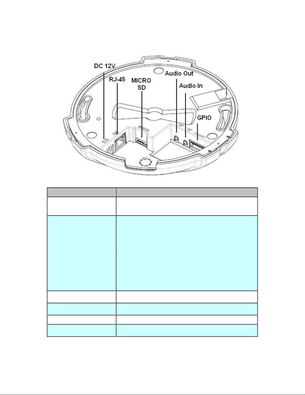
Rear View
Power Jack
RJ-45 LAN socket
MicroSD Card Slot
Audio Out
Interface Description
The input power is DC 12V, 2A.
Note:ONLY use package power adapter supplied with the
internet. Otherwise, the product may be damaged.
Connect to PC or Hub/Switch.
For connect to 10Base -T Ethernet or 100Base-TX Fast
Ethernet cabling. This Et hernet port built auto-ne gotiation
protocol can detect or negotiate the transmission speed of the
network automatically. Please use CAT-5 cable to connect the
Network Camera to a 100Mbps Fast Ethernet network switch
or hub.
Power / Status LED (orange color)
This LED will be flashin g while camera DC power is on
camera starting, and this LED light while camera ready.
Network LED (green color)
This LED will be flashing while the ca mera accessing of the
camera.
The IP Camera has built-in a Micro SD card slot accepts Micro
SD memory card for image / video event recording.
Connect a loud speaker to the IP Camera. This is for voice
alerting and two-way audio.
Audio In
GPIO
Connect a microphone to the IP Camera.
The 7 pin terminal block includes 4 input ports and 1 output
ports.
Page 11

Terminal block for I/O connectors:
Name Pin Function
GND 1
Digital input 4 2
Digital input 3 3
Digital input 2 4
Digital input 1 5
DO_NO 6
DO_COM 7
Four sets of Digital Input, DI1 until DI4; the internal device
is also photo-coupled electrical relay. In practi ce, the
external device can be simply an On/Off switch. Four sets
of On/Off switch can b e connected as different trigger
source.
Digital output implementation; Pin6 to COM (Pin7 ) is a
Photo-coupled relay on Normal Open status. External
device can directly connect to the terminals. However the
current that will go throug h the 2 node s must not exceed
130mA. An external “Relay” can also be connected to the
terminals as an implem entation. In this ca se, current
(or/and voltage) limitation is specifie d by the external
Relay.
Page 12
2.3 15BHardware Installation
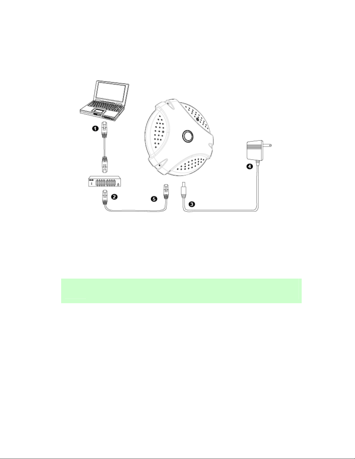
31B2.3.1 Physical Installation
Step 1. Prepare a PC with Ethernet link to th e network
Step 2. Connect an Ethernet cable
Connect LAN port (RJ-45) of the IP Camera to a network switch. Attach the power
supply
Plug in power adapter to IP Camera and connect another end to power outlet.
Only use the power adapter supplied with IP Camera otherwise, the product may
NOTE:
Step 3. Plug Power on 110v or 220V
Step 4. Check LED status
be damaged.
Ensure the powe r adaptor specification matches the power sy stem (110V AC or
220V AC) and connect the adaptor to the outlet
The Power LED is defined to identify IP Camera status. When IP Camera booting
the LED will be flashing and while IP Camera is ready the LED will be green.
Page 13

32B2.3.2 Wall/Ceiling Mount Installation Procedure
Step1. Take the wall mount bracket, put it on the target place and fix it with the supplied
screws (total of 2).
Step2. Load the camera into the wall mount, be sure the cameras are mated with two fixed
screw, and rotate the camera to lock it in position.
Page 14
2.4 16BInitial Utility Installation
This chapter shows how to quick set up your IP Camera. The IP Camera is with the default
settings. However to help you find the networked IP Camera quickly the Windows utility (PLANET
IPInstaller) can search the IP Cameras in the network that shall help you to configure some basic
setting before you start advanced management and monitoring.
Please insert the bundle CD disk into your CD/DV D-ROM drive. When the welcome web page
appears, please click your IP Camera name on the IP Camera list i.e. ICA-HM830W. Then click on
the utility IPInstaller to start the program.
2.5 17BPreparation
When you installed the ca mera on a L AN environment, you may execute PLANET IPInstaller to
discover camera’s IP address and set up related parameters in the camera.
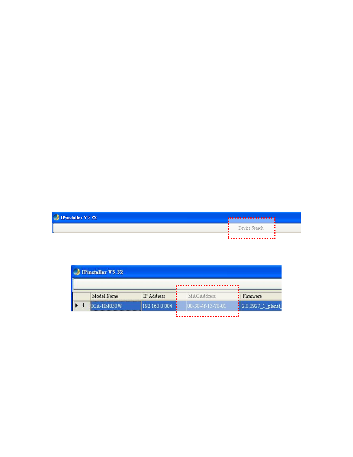
33B2.5.1 Configure Network by PLANET IPInstaller
Please click “Device Search” button. PLANET IPInstaller will list all networked IP Camera in the
LAN. If the IP Camera do esn’t be fou nd, you may check whether this IP Camera is connect to
network properly and press the search button again.
1. Click the menu bar Tool > Device Search to search the device in the LAN.
2. Select IP Camera with the MAC Address corresponds to the IP Camera that is to be
configured.
Page 15
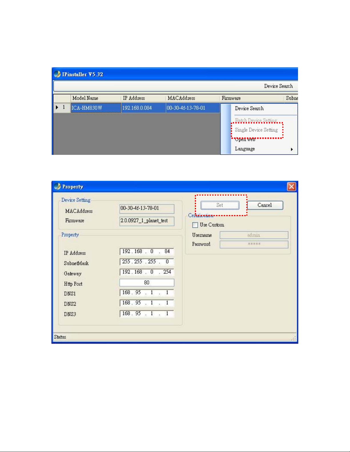
3. Double click the item to open the Property Page or click the menu bar > Single Device
Seeting
4. After filling the desired settings in the properties, click on “Set” button to complete the
configuration settings.
Page 16
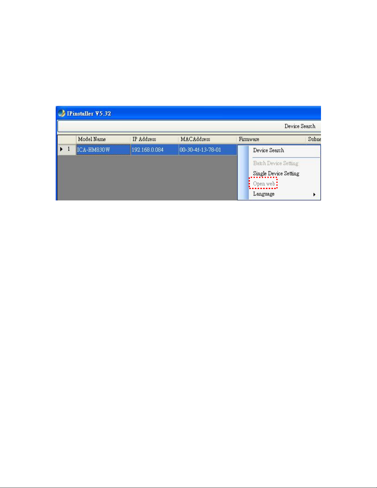
34B2.5.2 Open the Web-based UI of the select camera b-based UI of the select camera
If IPInstaller finds IP Camera, please select the device you want to view and click the “Open
If IPInstaller finds IP Camera, please select the device you want to view and click the “Open
Web” button. Then you could see the video from IP Camera directly.
Web” button. Then you could see the video from IP Camera directly.
1. To access the Web-based UI of the selected unit, run the menu bar > Open web on the
1. To access the Web-based UI of the selected unit, run the menu bar > Open web on the
menu bar.
menu bar.
If the Internet Camera has been configured correctly, the default Web browser will open to the
home page of the selected device.
If you find your browser is opened and automatically connected to the camera Home Page, it
means you’ve assigned an IP Address to the unit successfully. Now you can close the IP Installer
and start to use your camera.
Page 17
2.6 18BSetup ActiveX to use the Internet Camera
The Internet Camera web pages communicate with the Internet Camera using an ActiveX control.
The ActiveX control must be downloaded from the Internet Camera and installed on your PC. Your
Internet Explorer security settings mu st allow for the web pag e to work correctly. To use th e
Internet Camera, user must setup his IE browser as follows:
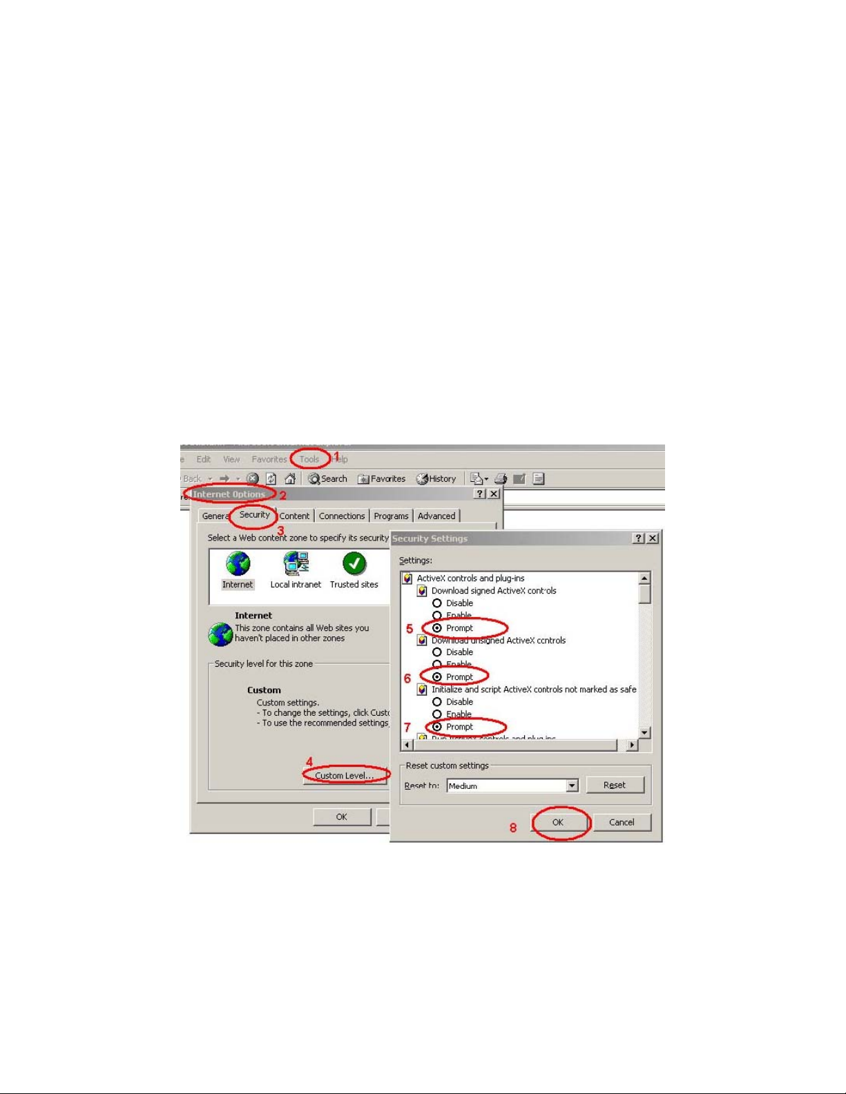
35B2.6.1 Internet Explorer 6 for Windows XP
From your IE browse Î ”Tools” Î ”Internet Options…” Î ”Security” ΔCustom Level…”, please
setup your “Settings” as follow.
Set the first 3 items
• Download the signed A ctiveX co ntrols
• Download the unsigned ActiveX controls
• Initialize and script the ActiveX controls not masked as safe to Prompt
By now, you have finished your entire PC configuration for Internet Camera.
Page 18
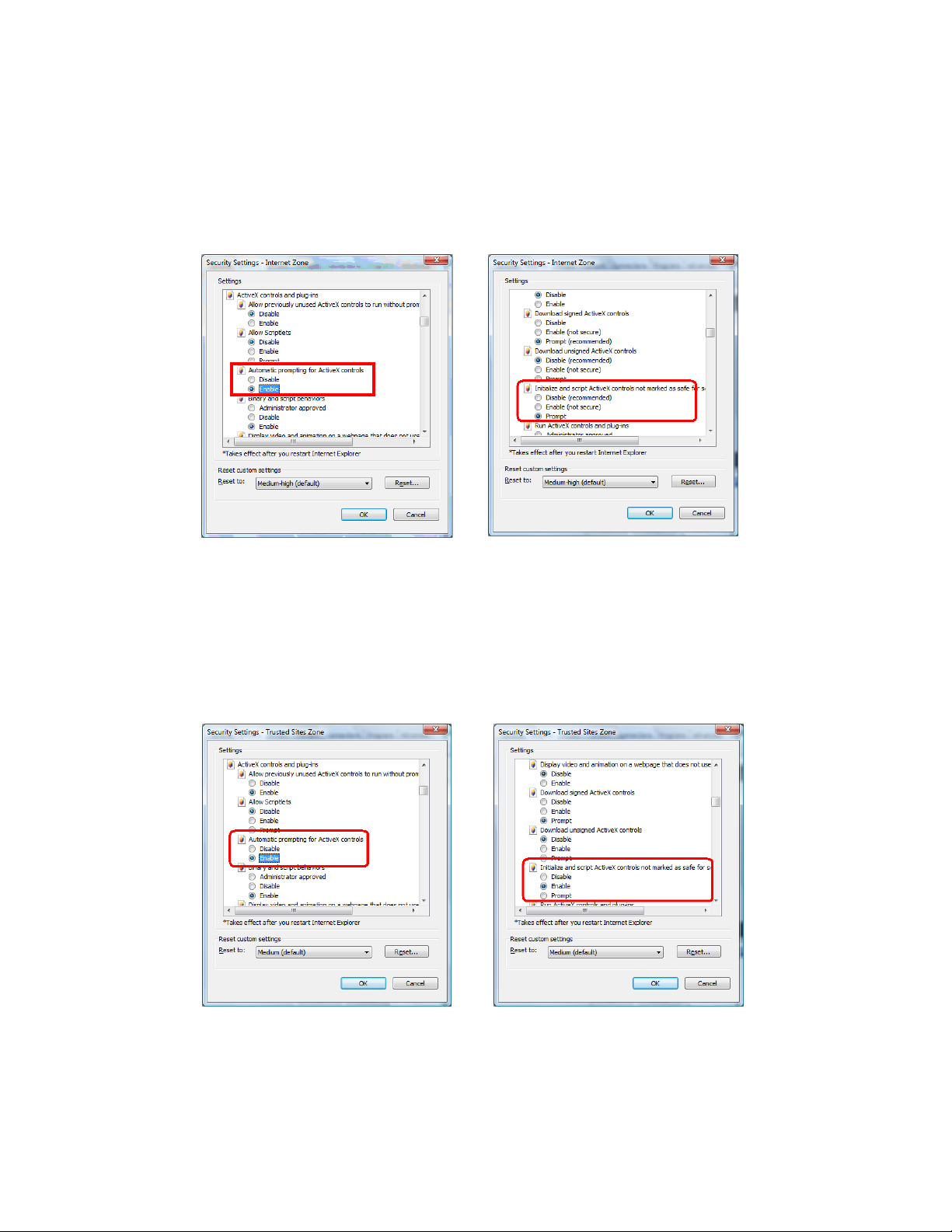
36B2.6.2 Internet Explorer 7 for Windows XP
From your IE browse Î ”Tools” Î ”Internet Options…” Î ”Security” ΔCustom Level…”, please
setup your “Settings” as follow.
Set the first 3 items
• Allow previously unused ActiveX control to run…
• Allows Script lets
• Automatic prompting for ActiveX controls
By now, you have finished your entire PC configuration for Internet Camera.
Page 19
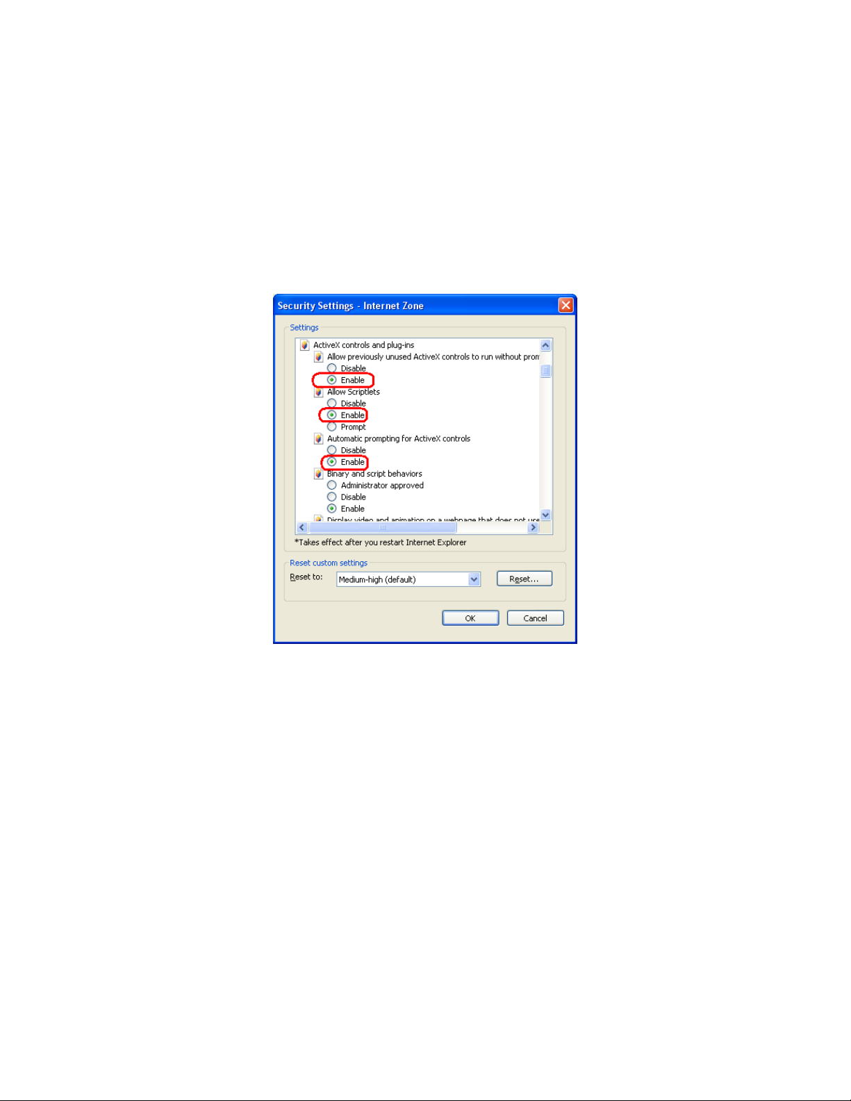
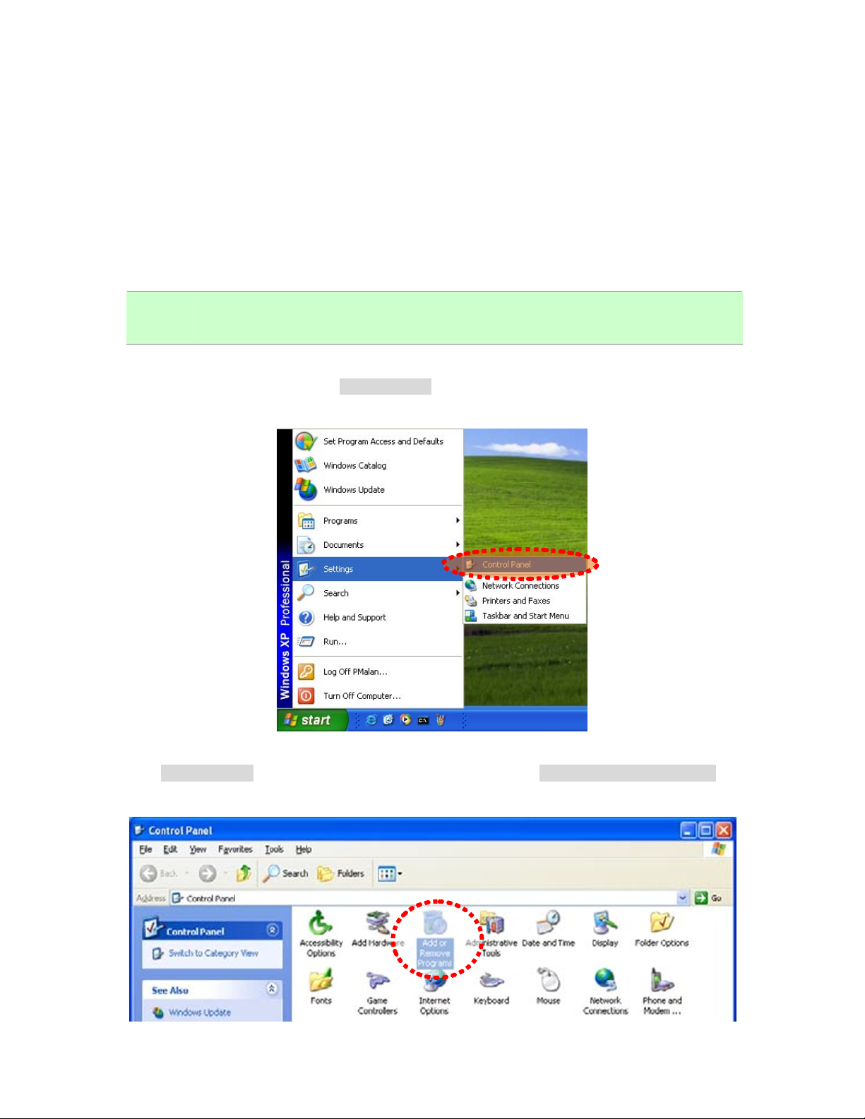
37B2.6.3 Internet Explorer 7 for Windows Vista sta
From your IE browse Î ”Tools” Î ”Internet Options…” Î ”Security” Î ”Internet” ΔCustom
From your IE browse Î ”Tools” Î ”Internet Options…” Î ”Security” Î ”Internet” ΔCustom
Level…”, please setup your “Settings” as follow.
Level…”, please setup your “Settings” as follow.
• Enable “Automatic prompting for ActiveX controls” • Enable “Automatic prompting for ActiveX controls”
• Prompt “Initialize and script active controls not marked….” • Prompt “Initialize and script active controls not marked….”
From your I E browse Î ”Tools” Î ”Internet Option s…” Î ”Security” Î ”Trusted Sites”
ΔCustom Level…”, please setup your “Settings” as follow.
• Enable “Automatic prompting for ActiveX controls”
• Prompt “Initialize and script active controls not marked….”
By now, you have finished your entire PC configuration for Internet Camera.
Page 20
2.7 19BUsing UPnP of Windows XP or Vista UPnP of Windows XP or Vista
38B2.7.1 Windows XP38B2.7.1 Windows XP
UPnP™ is short for Universal Plug a nd Play, whi ch is a n etworking architecture that p rovides
UPnP™ is short for Universal Plug a nd Play, whi ch is a n etworking architecture that p rovides
compatibility among network ing equipment, software, and perip herals. This device is an UPnP
compatibility among network ing equipment, software, and perip herals. This device is an UPnP
enabled device. If the operating system, Windows XP, of your PC is UP nP enabled, the Internet
enabled device. If the operating system, Windows XP, of your PC is UP nP enabled, the Internet
Camera will be very easy to configure. Use the following steps to enable UPnP settings only if your
Camera will be very easy to configure. Use the following steps to enable UPnP settings only if your
operating system of PC is running Windows XP.
operating system of PC is running Windows XP.
NOTE: Windows 2000 does not support UPnP feature.
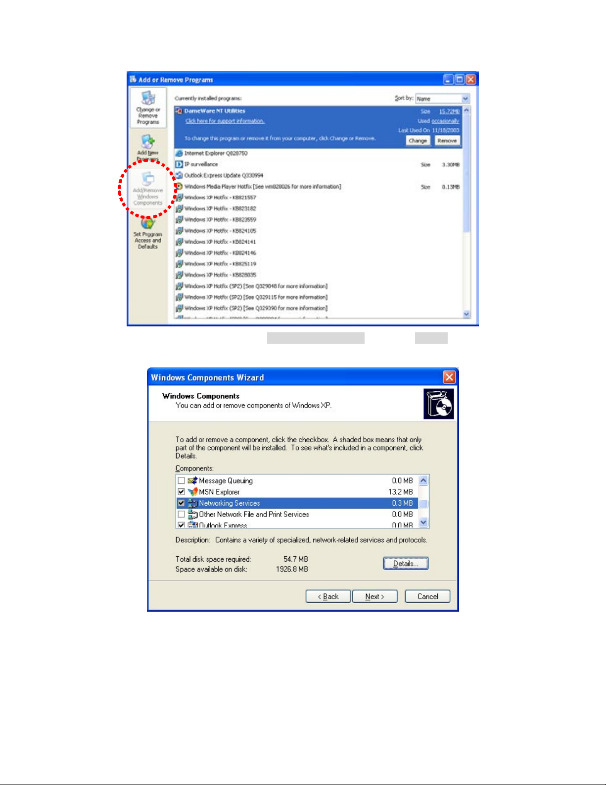
Go to Start > Settings, and Click Control Panel
The “Control Panel” will display on the screen and double click “Add or Remove Programs” to
continue
The “Add or Remove Programs” will display on the screen and click Add/Remove Widows
Components to continue.
Page 21
The following screen will appear, select “Networking Services” and click “Details” to continue
Page 22
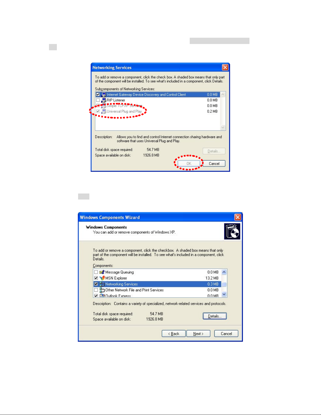
The “Networking Services” will display on the screen, select “Universal Plug and Play” and click
“OK” to continue.
Please click “Next” to continue
Page 23
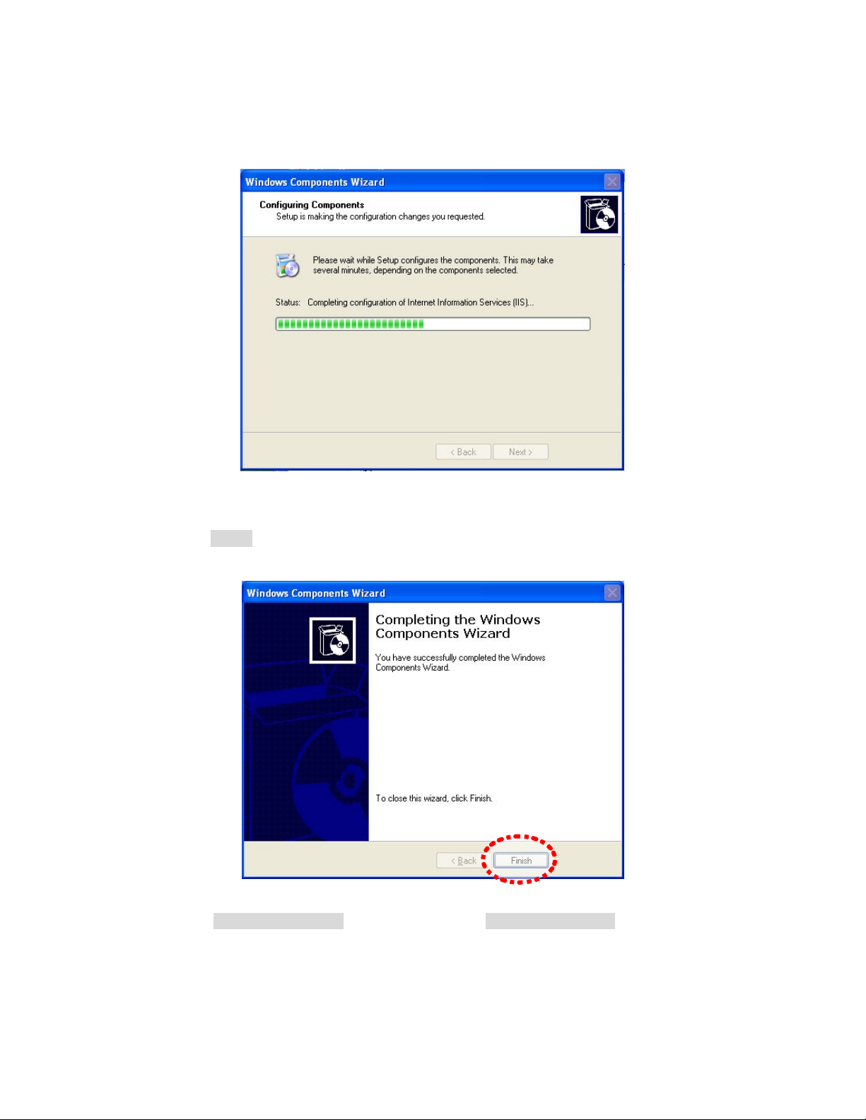
The program will start inst alling the UP nP automatically. You will see t he below pop-up screen,
please wait while Setup configures the components.
Please click “Finish” to complete the UPnP installation
Double-click “My Network Places” on the desktop, the “My Network Places” will display on the
screen and d ouble-click the UPnP ico n with Internet Camera to view your d evice in an inte rnet
browser.
Page 24
39B2.7.2 Windows Vista
UPnP™ is short for Universal Plug a nd Play, whi ch is a n etworking architecture that p rovides
UPnP™ is short for Universal Plug a nd Play, whi ch is a n etworking architecture that p rovides
compatibility among network ing equipment, software, and perip herals. This device is an UPnP
compatibility among network ing equipment, software, and perip herals. This device is an UPnP
enabled device. If the operating system, Windows Vista, of your PC is UPnP enabled, the Internet
enabled device. If the operating system, Windows Vista, of your PC is UPnP enabled, the Internet
Camera will be very easy to configure. Use the following steps to enable UPnP settings only if your
Camera will be very easy to configure. Use the following steps to enable UPnP settings only if your
operating system of PC is running Windows Vista.
operating system of PC is running Windows Vista.
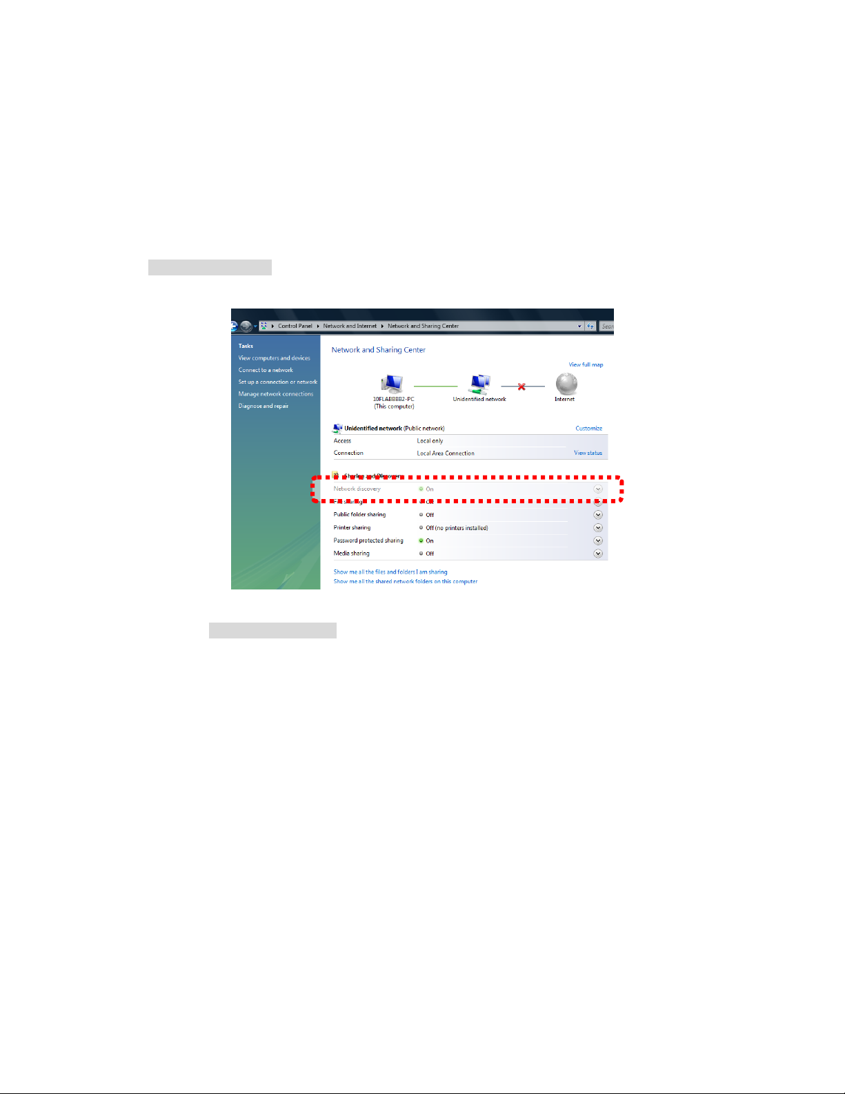
Go to Start > Control Panel > Network and Internet > Network and Sharing Center, and turn Go to Start > Control Panel > Network and Internet > Network and Sharing Center, and turn
on “Network Discovery”.
Double-click “My Network Places“ on the desktop, the “My Net work Places” will display on the
screen and double-click the UPnP icon with Internet Camera to view your device in an internet
browser.
Page 25
3. 2BWeb-based Management
This chapter provides setup details of the Internet Camera’s Web-based Interface.
20B3.1 Introduction
The Internet Camera can be configured with you r Web Browser. Before configure, please make
sure your PC is under the same IP segment with Internet Camera.
21B3.2 Connecting to Internet Camera
z Use the following procedure to establish a connection from your PC to the camera.
z Once connected, you can add the camera to your Browser’s Favorites or Bookmarks.
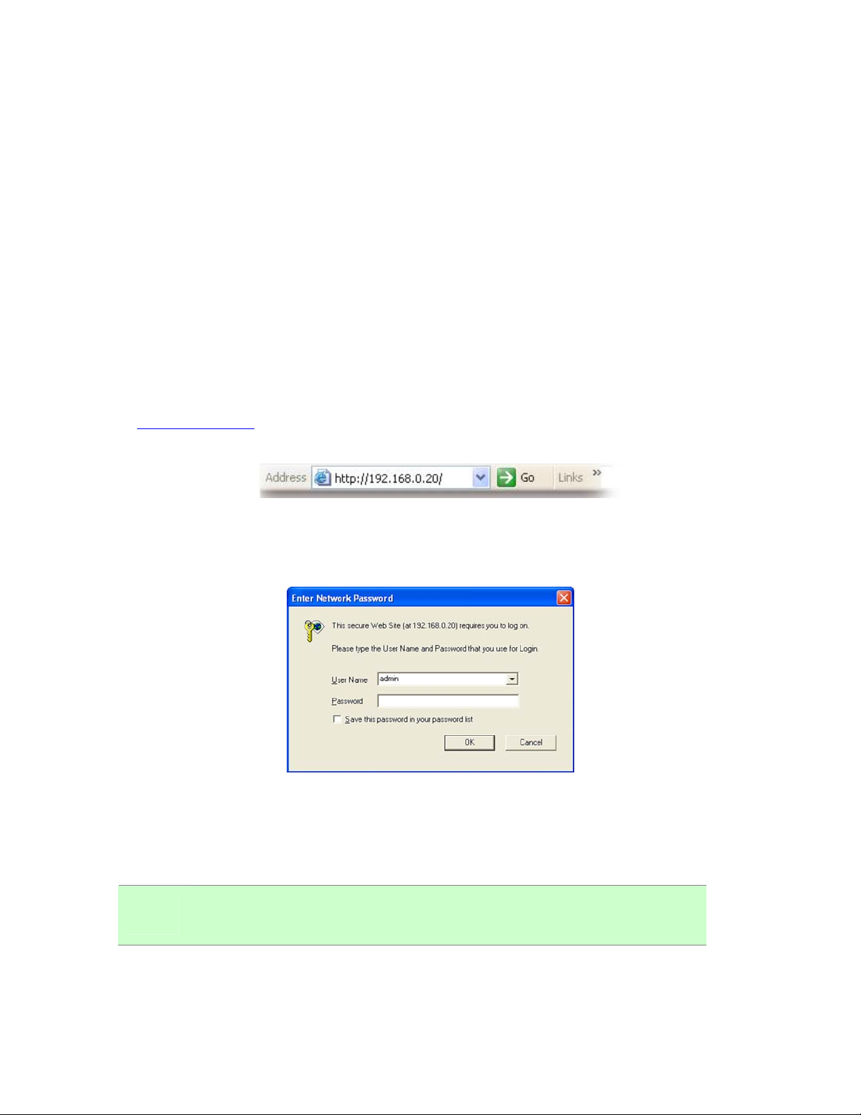
Start the web browser on the computer and type the IP address of the camera. The Default IP:
“
HUhttp://192.168.0.20UH “
After connected to IP Camera, it will prompt for User Name and Password, please enter
admin/admin to continue Web Management. Confirm the installation as it is required to view the
video stream and some operations.
If difficulty is met, please refer to the following steps to establish the connection:
- The IP Camera must be installed and powered ON.
- If the IP Camera’s default IP Address (192.168.0.20) is already used by another device, the
other device must be turned OFF until the device is allocated a new IP Address during
configuration.
-
NOTE:
If the User name and Password have been changed with PLANET IPInstaller,
please enter the new User name and Password here.
Page 26

For the first installation, there will be a prompt to install the ActiveX control.
Click on the message, and click Install ActiveX Control…
When you see this message, click Install’ to install required ActiveX control
Page 27

If the device has been configured correctly, the default Web browser will open to the home page of
the selected device.
If you log in the Internet Camera as an ordinary user, setting function will be not
NOTE:
available. If you log in the camera as the administrator, you can perform all the
settings provided within the Internet Camera.
Page 28

22B3.3 Live View
guag
Start-up screen will be as follow no matter an ordinary users or an administrator.
Camera IP Stream Type
Setup Manual
Live Image Control
Monitor Image Section
Lan
Resolution Farm Rate
eMonitor Live Image Size
Display Mode
Bit Rate
Digital PTZ
Manual Trigger
Button Description
z Video:Configure bit rate, frame rate and resolution of video profiles.
z Camera:Adjust camera general parameters, such as image rotate,
Brightness, audio, record parameters.
z Event:Configure the event server, I/O ports information, and object
motion detection settings.
z Schedule:Configure the event schedule and storage while event
triggered.
z Network:Configure Network settings such as, SMTP, RTSP, DHCP,
DDNS, and UPnP, etc.
z System:Configure system information, date & time, maintenance,
and view system log file.
Page 29

Full screen
Monitor Listen
Monitor Talk
(2-way audio)
Video Record
The Internet Camera could provide multiple languages to meet customer’s
requirement. (English, Traditional Chinese and Simplified Chinese)
Select display mode to view the different type of the image.
The Internet Camera allow user to di splay the liv e video in a ctual size
mode.
(Uses every available space to display the image captured by this camera).
The camera allow user to trigger the alarm manu ally. User can click the
button active the alarm immediately while a suspicious object discovered.
The Digital PTZ button ca n control camera up/down/left/right and zoom
in/out position.
Button Description
Click the ico n can di splay the image in full-screen mode (uses every browser
available space to display the image captured by this camera).
Click the icon can listen for the audio input from local end.
The Internet Camera supports 2-way audio function. User can chose to enable or
Snapshot
disable this function by toggling the icon.
Click the icon be able to activate the record function start recording. The video
file is saved as AVI format into your local PC.
Click the icon be able to activate the snapshot function to take a picture.
Page 30

23B3.4 Video Configuration
This Internet Camera provides multiple video stream profiles as below to support different request
to each clie nt simultaneously. Each user can choose preferred video pro file as his reque st
independently.
40B3.4.1 Video General Settings
The menu allow user to disable/enable OSD.
OSD Setting:
There are some important information can be e mbedded into image,
including date, time, and/or camera name.
NOTE: When the configuration is finish, please click “Save” to save and enable the setting.
Page 31

1. Ch: Select the channel. (1~4)
2. Step: The speed of the camera move. (1~10)
3. Pan Tilt control of this IP camera
4. Zoom: Digital zooms in/out. (1~10)
5. Move the box.
6. Close the box.
Page 32

41B3.4.2 Video Advanced Settings
This Internet Camera provides video stream profiles to support different request. The stream 1 can
up to maximum resolution 1600 x 1200 (2 Mega Pixel).
RTSP Path
It is the strea m ID used fo r RTSP client streaming connection, such
as VLC player. (Default v00).
Resolution Image size 1600x1200
Choose between variable bit rate (VBR) and constant bit rate (CBR)
VBR:
User should choose the q uality level to set the vide o quality rath er
Video Modes
than bit rate.
CBR:
The video bit rate is between low to high bandwidth based on different
resolutions. User can set the bit rate range from 64 to 6000kb
Target Bit Rates(CBR) Choose the number of frames to encode per second.
Quality Level(VBR)
The quality level is bet ween Standard and Best. The be st level can
reach the better quality but of course will consume higher bandwidth.
Image Format 2 kinds of format to choose from; H.264 and M-JPEG
GOP Defines the Intra/Inter-frame (I/P) ratio of this profile.
Frame Rates
Choose the number of frames to displa y per second. With resolution
1600x1200, FPS can only set up to 15FPS.
Page 33

42B3.4.3 External Video Source
The Internet Camera provided the video conference feature, if you have multiple Internet Cameras
(ICA-HM830W) within your system, you can monitor the video of remote connected camera form
the browser.
Page 34

External Video Source
List
External Video Source
Setup
Connect
List all of external camera for user selection while video conference.
Maximum number of external is 10.
According to remote camera video settings to setup those parameters
into the list.
When the configuration is finish, please click the b utton to make the
video test.
24B3.5 Camera Configuration
Use this menu to set the function of the camera of Internet Camera
43B3.5.1 Camera General Settings
Page 35

Adjust the image parameters for a better view.
Brightness:
Large value will brighten camera.
Camera General setting
Audio Setting To enable or disable audio function.
Hue:
Large value will be colorful.
Saturation:
Large value will contrast camera heavily.
Save Path / File name:
Web Record Setting
Web Snapshot Image
Setting
Default Set “Camera General Setting’ and ‘Audio Setting” back to default
Click on the “Browse” button to select the desi red path to save as
well as naming the video file.
Save Path / File name:
Click on the “Browse” button to select the desi red path to save as
well as naming the video file.
Page 36

44B3.5.2 Camera Advanced Settings
The menu allow user to adjust the camera white balance, exposure, gain control and ICR active
mode.
White Balance
Exposure
Adjust the white balance according to the environment
Auto: will adjust the white balance setting automatically.
Hold: will hold the white balance setting.
Sunny: will fix the color temperature with sunny day mode.
Cloudy: will fix the color temperature with cloudy day mode.
Indoor: will fix the color temperature with indoor mode.
Automatic: will adjust the internal gain automatically.
Flicker-free 50Hz: will effects of exposure to 50Hz.
Page 37

Flicker-free 60Hz: will effects of exposure to 60Hz.
Max Exposure Time
Max Gain Control To adjust maximum gain of input video.
Infrared (IR) Cut Filter
Camera Mount 3 kinds of format to choose from; Wall, Ceiling and Table.
Ceiling Mode:5 kinds of format to choose.
360° Source image 180° double broad view
Increase / reduce the exposure time for lens.
User can turn Auto or se tting for fix mode. This f unction is very
useful under low illumination environment.
360° source view with 3 PTZ
Quad view
360° broad view with 2 PTZ
Page 38

Wall Mode:2 kinds of format to choose.
180° source view with 3 PTZ 180° broad view with 2 PTZ
Table Mode:2 kinds of format to choose.
360°Table view
180° double table broad view
Page 39

25B3.6 Event Configuration
This menu is used to specify the schedule of Events and activate the some actions provided by
this device.
45B3.6.1 Event Server
The Internet Camera supports FTP upload function that will upload image while event trigger.
46B3.6.1.1 FTP server
You may setup FTP para meters for further ope ration of Event Schedule. That’s, if users want to
send the alarm message to an FTP server.
Page 40

FTP Server Name:
User can specify a FTP server as wish. Therefore, user needs to
specify a name for each FTP setting.
Network:
Type the server name or the IP address of the FTP server.
Upload Path:
Set working directory path of FTP server.
Port:
Set port number of FTP service.
Login Information User Name:
Type the user name for the FTP server.
Password:
Type the password for the FTP server.
47B3.6.1.2 Event Server Remove
When want to delete the unnecessary servers, user just need to click “Remove” button to delete
selected event servers.
Page 41

48B3.6.2 Motion Detection
Use this menu to specify motion detection window and set the conditions for detection while
observing a captured image.
Add a motion detection area please click on “Add” to set up a detection area as indicated below.
Page 42

Motion Detection List Add and Del:
To add or delete the motion windows. User can specify up to 10 areas
to monitor the video captured by th is device. By draggin g mouse on
the bar, you can change the trigger and sensitivity level of the detect
motion area accordingly.
Motion Detection Setup Window Area Name:
Name of the specified motion area.
Trigger Level:
Defines the trigge r level of motion detection for this detectio n area.
(0~100, low~high)
Sensitivity:
Defines the sensitivity value of mo tion detection. The higher value will
be more sensitivity. (0~100, low~high)
Color Select color for detection area indication.
View All Windows Displays all detection windows on screen.
View Selected Window Only displays selected detection window on screen.
Page 43

49B3.6.3 I/O Ports
The Camera can be activated by the external sensor that senses physical changes in the area
Camera is monitoring. These changes can include intrusion detection or certain physical change
in the monitored area.
Input ports setting Name:
The field needs to specify a name for input sensor setting.
Current Status:
The field displays the input port current status.
Output Ports setting Name:
The field needs to specify a name for output sensor setting.
Current Status:
The field displayed the output port current status.
Page 44

50B3.6.4 Event Configuration
This menu is used to specify the trigger of Events and activate the some actions provided by this
device.
To add an event trigger, please click on “Add” and setup panel will be expanded.
Page 45

Event Type Setup Name:
Name of the Event or Schedule.
Set min time between trigger:
Set the time interval between each trigger.
Respond to Trigger:
Set the time period for the trigger.
9 Always:
Active the selected event immediate and continuous.
9 Only during time frame:
Choose a da y and the sta rting time then configure the
duration time (168hrs = 24x7). If durati on time is set to
168(hrs), it is the same as choosing “Always”
9 Never:
Stop the selected event immediately.
Trigger by:
Select the triggered sources with event trigger.
When Triggered … Upload Images:
Upload captured image to event server once event trigged.
Page 46

Activate Output Port:
Activate the external alarm once event trigged.
Send Email Notification:
Send notification through SMTP server once event trigged.
Send Message Notification(TCP):
Send notification through TCP server once event trigged.
26B3.7 Schedule Configuration
This menu is used to specify the schedule of Events and activate the some actions provided by
this device.
51B3.7.1 General Setting
The page define the day (specified by days of a week) and time (specified by each single hour) for
that will be recording during the scheduled period.
Note that only video data will be recorded. User can select which video stream should be recorded,
and the size of each sliced file. When the check box is ticked and setting is saved, recording
process starts. Recording files are saved to the Micro SD storage.
Enable Enable or disable this schedule record.
Stream Select one of the stream profiles for video recorded.
Slice File Size Define the sliced file size for each recording files.
Save Device type The storage device information.
Page 47

52B3.7.2 Storage Setting
The page display the storage inform ation, includes disk size info, type and status. The wa rning
message shows when recording is on process. The SD card sho uld not be removed during the
recording process.
Disk Status Refresh:
User can click the button refreshes the status displayed of SD card.
Browse:
User can click the button to download the file on SD card.
Remove Event Image:
User can click the button remove the event image.
Local Disk Setting The Internet Camera support the local Micro SD di sk feature, user can
mark the check box to active the function.
Format:
When insert a new Micro SD/SDHC card, user simply click the button to
complete the disk format operation in the Internet Camera.
Page 48

27B3.8 Network Configuration
Use this menu to configure the network to connect the Internet Camera and the clients. u to configure the network to connect the Internet Camera and the clients.
53B3.8.1 Network General Settings 53B3.8.1 Network General Settings
This section provides the menu of connecting the Internet Camera through Ethernet cable. This section provides the menu of connecting the Internet Camera through Ethernet cable.
DHCP Service
Static IP Address
Enable this checked box when a DHCP server is inst alled on the
network to i ssue IP address assignment. With t his setting, the IP
address is assigned automatically.
If you do not select “DHCP Service”, then you need to enter th ese
network parameters by yourself.
Please type in IP address, Subnet Mask, Gateway, DNS manually.
IP address:
This IP address is a uni que numbers that identifies a co mputer or
device on the LAN. The se numbers are usually shown in g roups
separated by periods, for example: 192.168.0.20
Subnet Mask:
Subnets allow network traffic between hosts to be separated based on
the network's configuration. In IP networking, traffic takes the fo rm of
packets. IP subnets advance network se curity and perf ormance to
Page 49

some level by organizing hosts into logical g roups. Subnet masks
contain four bytes and usually appear in the sa me "dotted decimal"
data. For e xample, a very comm on subnet ma sk in it s binary
demonstration 11111111 11111111 11111111 00000000 will usually be
shown in the corresponding, more readable form as 255.255.255.0.
Gateway:
A gateway is a piece of so ftware or hardware that passes information
between networks. You'll see this term most often when you either log
in to an Inte rnet site or when you're transient email between different
servers.
DNS:
When you send email or position a browser to an Internet domain such
as xxxxx.com, the domain name system translates the names into IP
addresses. The term refers to two things: the conventions for naming
hosts and the way the names are control across the Internet.
Enable ARP/Ping
Enable the camera to accept ARP or ping packet s from the network. If
disable this option may provide extra security from intentional ping.
54B3.8.2 Network Advanced Settings
NTP Configuration
Configure a NTP (Network Time Prot ocol) server so that the camera
system date and time can be syn chronized with a specifie d Time
Server. This configuration is provided for one of the p otions of system
Page 50

date/time adjustment.
HTTP Setting
The Internet Camera supports changeable HTTP ports. This port is
very useful for Intranet usage. Users could assign the port number of
http protocol, and the WAN users should follow th e port n umber to
login. If the http port is not assi gned as 80, users have to add the port
number in back of IP address. For example:
Therefore, the user can access the Internet Camera by either
Uhttp://xx.xx.xx.xx/U, or
Uhttp://xx.xx.xx.xx:xxxx/ Uto access the Internet Camera.
If multiple devices a re installed on the LAN and al so required to be
accessed from the WAN, then the HTTP Port can be assigned as the
virtual server port mapping to support multiple devices.
RTSP Setting RTSP Port:
The RTSP protocol allows a connecting client to start a video stream.
Enter the RTSP port number to use. (The default value is 554)
HTTPS Setting Enable HTTPS:
The HTTPS service is a combi nation of the HHypertext Transfer
ProtocolH with the HSSL/TLSH protocol to provide encryption and secure
identification of the camera access.
Uhttp://192.168.0.20:8080U.
Bonjour Setting Enable Bonjour:
The Bonjour service allows camera can be discove red with App le
Safari browser applied that will show in the Bonjour bookmarks menu.
UPnP Notification Enable UPnP:
The UPnP function allows camera can automatically be detected and
a new icon will be add ed to “My Network Pla ces” if your operating
system is UPnP enabled.
NAT Traversal Setting Enable NAT Traversal:
When enabled, the Internet Camera will attempt to configure port
mapping in a NAT router on your network.
Page 51

55B3.8.3 Network SMTP Settings
You may set up SMTP mail param eters for further operation of Event Schedul e. That’s, if users
want to send the alarm m essage out, it will need to configure parameters here and al so add at
least one event schedule to enable event triggering.
SMTP (email) Setting Mail Server:
Type the SMTP server name or the IP address of the SMTP server.
Server Port:
Set port number of SMTP service.(The default value is 25)
Authentication:
Select the authentication required when you send an e-mail.
User Name:
Type the user name for the SMTP server if Authentication is Enable.
Password:
Type the password for the SMTP server if Authentication is Enable.
From (Email Address):
Type the se nder’s E-mail address. This address is used for reply
e-mails.
Test Send test email to:
Send a test mail to mail server to check this account is available or not.
Page 52

56B3.8.4 DDNS server
DDNS: Stands for Dynamic Domain Name Server
The Internet Camera supports DDNS If your device is connected to xDSL directly, you might need
this feature. Ho wever, if y our device is behind a NAT router, you will not need to enable this
feature. Because DDNS allows the Internet Came ra to use a n easier way to re member naming
format rather than a n IP address. The Internet uses DNS se rvers to lookup domain names and
translates them into IP a ddresses. Domain names are just easy to remember alia ses for IP
addresses. A dynamic DNS se rvice is unique because it provides a means of updating your IP
address so that your listing will remain current when your IP address changes. There are several
excellent DDNS se rvices available on the Intern et and best of all they’re free t o use. One such
service you can use i s www.DynDNS.org. You’ll need to register with the service and set up the
domain name of your cho ice to begin using it. Plea se refer to the home page of the service for
detailed instructions or refer to Appendix E for more information.
Dynamic DNS Setting DDNS:
To enable or disable the DDNS service here.
DDNS Host:
The domain name is applied of this device.
User Name:
The user name is used to log into DDNS.
Password:
The password is used to log into DDNS.
Update Time:
Periodically, the Internet Camera updates its access info to sever
in the configured time.
Response:
The Internet Camera responds the connection info.
Page 53

57B3.8.5 Wireless
Wireless Connection Select Enable to activate wireless network function of this IP camera,
select Disable to disable it.
IP Setting Mode DHCP Service:
Enable this checked box when a DHCP server is installed on the
network to i ssue IP address assignment. With this setting, the IP
address is assigned automatically.
Static IP Address:
Page 54

Please type in IP address, Netmask, Gateway manually.
Mode Select the network type of wireless connection.
Available options are Infrastructure (Connect the IP camera to a
wireless access point), and Adhoc (This IP camera will become a
stand-alone wireless network point, other wireless computers /
devices can discover this IP camera and connect to it without wireless
access point).
You can set to Adhoc when you d on’t have any wirel ess access
point, but your computer has wireless network card. Set to
‘Infrastructure’ when yo u have wireless access point, and you h ave
computers with wired network connection.
Operation Mode AUTO: Allows user to set the 802.11bgn standard wireless network
11B: Allows user to set the 802.11b standard wireless network.
11G: Allows user to set the 802.11g standard wireless network.
SSID Input the SSID of the wireless access point you wish to connect. It
should be less than 32 alphanumerical characters.
Security It supports “None”, “WEP”, “WPA-PSK” ,“WPA2-PSK” security
encryption based on the setting of the Router.
ADHOC Setting
Operation Mode
SSID
Security
Domain
AUTO: Allows user to set the 802.11bgn standard wireless network
11B: Allows user to set the 802.11b standard wireless network.
11G: Allows user to set the 802.11g standard wireless network.
Input the SSID of the wireless access point you wish to connect. It should
be less than 32 alphanumerical characters.
It supports “None”, “WEP” security encryption based on the setting of the
Router.
FCC(1~11CH) , ETSI(1~13CH) , JP(1~14CH)
Page 55

28B3.9 System Maintain
Use this menu to perform the principal settings of Internet Camera.
58B3.9.1 System Information
User can use this menu to get the system and network information of this camera and detailed
descriptions of every setting will be given below.
Page 56

59B3.9.2 User Account Configuration
If users wish to allow other people to view the live image captured by this camera, but don’t want
to allow them to modify system settings that can give them user-level user name and password, so
they can only view the image and can not change any system setting. When they want to click
menus other than Camera, they will see the following message informing that they don’t have
permission to do that:
User Setting Enable anonymous login (no user name or password required):
The check box allow any one viewing the video once connected. Otherwise,
only users in database can view the video after login.
Page 57

60B3.9.3 Date & Time Configuration
This setting allows user to change the date and time of the real time clock in this IP camera. User
can set the time manually, or use network time protocol (NTP) to set the time automatically.
Current Server Time Date & Time:
Displays the date and time of the Internet Camera.
Set Server Time Synchronize with computer time:
Click this option to enable time synchronizat ion with PC
time.
Synchronize with NTP server:
Click this option if you want to synchronize the Internet Camera’s
date and time with those of time server called NTP server (Network
Time Protocol).
Time zone:
Please select the time zone of the country / city of resident from
dropdown menu here.
Set Manually:
Click this option to set time and date manually.
Page 58

61B3.9.4 Server Maintenance
This menu allows user to upgrade firmware, clear all settings, reboot the IP camera, and backup
all parameters.
Maintain Server Reboot:
The Internet Camera is restarted without changing any of the settings.
Load Default:
Recall the Internet Camera hard factory default settings. Note that click
this button will reset all device’ s parameters to the factory set tings
including the IP address.
Firmware Upgrade The Internet Camera supports new firmware upgrade.
Step 1. Close all other application programs which are not necessary
for firmware update.
Page 59

Step 2. Make sure that only you access this device at this moment.
Step 3. Disable Motion Detection function.
Step 4. Select “Firmware name”.
Step 5. Select the Firmware binary file.
Step 6. Once the firmware file was selected, select “Upgrade”.
Step 7. The upgrade progress inf ormation will be displaye d on the
screen.
Step 8. A message will be shown while the firmware upgraded. Once
the upgrading process complet ed, the Internet Camera will
reboot the system automatically.
Please wait for upg rade procedural finished, and th en you ca n use
PLANET IPInstaller to search the Internet Camera again.
Warning!!!
The download firmware procedure can not be interrupted. If the power and/or network
connection are broken during the download procedure, it might possibly cause serious
damage to the Internet Camera.
Please be aware that you should not turn off the power during updating the firmware and
wait for finish message.
Furthermore, do not try to upgrade new firmware if it’s not necessary.
Backup Save all parameters and user-defined scripts to backup file:
To take a backup of a ll of the parameters, click this button. If
necessary, it will then be possible to re turn to the previous settings, if
settings are changed and there is unexpected behavior.
Upload setting Specify the backup file to use:
Click the “Browse” button to locate the saved backup file and then click
the “Restore Setting” button. The settings will be restored to the
previous configuration.
Add Language Choose language:
The Internet Camera could provide multiple languages to m eet
customer’s requirement.
Select language file to upload:
User can manually update other language into IP camera through
language file upload.
Page 60

62B3.9.5 Log Service
User can check the system log information of the camera, most system operations and/or process
will be kept in a log system. The link provided the review of these records.
29B3.10 Customize
The manual allow user can have custom web style, manual change the background, text color and
some description, etc.
63B3.10.1 Use Default Look
The parts may let user can manual add four hyperlinks at the live view page, user can type in other
camera IP or any website you want into the URL field.
Page 61

64B3.10.2 Use Custom Settings
The features allow the user can have custom settings for background color, text color and camera
description evens upload image to change.
Page 62

Logo & Link Tex t C ol or
Background Color & Picture
Description
Title
Page 63

3BAppendix A: Reset Factory Default Settings
There is a button hidden in the pinhole near to the Mic. This button is used to restore the all factory
default settings. Sometimes restarting the Internet Camera will make the system back to a normal
state. However, if the system still got problems after restart, user can restore the factory default
settings and install it again.
Restore the Internet Camera:
1. Unplug the power jack to turn of the power of ICA-HM830W.
2. Insert a pin into the reset hold a s indicated with orange in the below figures. Sense a button
and keep it pressed until instructed to release.
3. Plug in the power jack to turn ICA-HM 830W, in about 20 seconds t he LED indicator will be
flashing.
4. Release the button. (Remove the pin form the reset hold)
5. The ICA-HM830W could now back to factory default. Have an access to the Internet Camera
by changing to the attempt IP address from the default 192.168.0.20.
NOTE:
Restoring the factory default setting will lose the all previous settings included IP
address forever. User needs to run the PLANET IPInstaller program to search the unit
and configure it to let the Internet Camera work properly again.
Page 64

4BAppendix B: PING IP Address
The PING (stands for Packet Internet Grop er) command is used to detect whether a spe cific IP
address is accessible by sending a packet to the specific address and waiting for a reply. It’s also
a very useful tool to confirm Internet Camera installed or if the IP address conflicts with any other
devices over the network.
If you want to make sure the IP address of Internet Camera, utilize the PING command as follows:
z Start a DOS window.
z Type ping x.x.x.x, where x.x.x.x is the IP address of the Internet Camera.
The replies, as illustrated below, will provide an explanation to the problem.
If you want to detect any other devices conflicts with the IP address of Internet Camera, also can
utilize the PING command but you must disconnect the Internet Camera from the network first.
Page 65

5BAppendix C:
Bandwidth and Video Size Estimation
The frame rate of video tra nsmitted from the Internet Camera depends on connection bandwidth
between client and serve r, video re solution, codec type, and qu ality setting of server. Here is a
guideline to help you roughly estimate the bandwidth requirements for your Internet Camera.
The required bandwidth depends on content of video source. The slow motion video will produce
smaller bit rate generally and fast moti on will produce higher bit rate vice versa. Actual results
generated by the Internet Camera may be varying.
Image Resolution
320 x 240
(QVGA)
640 x 480
(VGA)
1280x1024
(SXGA)
1600x1200
(UXGA)
Average range of data sizes for
M-JPEG mode
8 ~ 20k byte per frame
20 ~ 50K byte per frame
100 ~ 200k byte per frame
600 ~ 1500k byte per frame
Average bit rate for H.264 mode
192kbps~512kbps
@ 30fps
384kbps~1536kbps
@ 30fps
512kbps~3076kbps
@ 15fps
640kbps~6144kbps
@ 15fps
NOTE:
Audio streaming also takes bandwidth around 5 kbps to 64kbps. Most xDSL/Cable
modem upload speeds may not even reach up to 128 kbps. Thus, you may not be able
to receive any video while streaming audio on a 128 kbps or lower connection. Even
though the upload speed is more than 128kbps, for optimal video performance,
disabling audio streaming will get better video performance.
Page 66

6BAppendix D: DDNS Application
1. Preface . Preface
If you have a Cable modem or xDSL, this is a great way to host your own Networked Device or
If you have a Cable modem or xDSL, this is a great way to host your own Networked Device or
other TCP/IP Service. Get your own domain like www.yourname.com, www.yourname.com.tw
other TCP/IP Service. Get your own domain like www.yourname.com, www.yourname.com.tw
etc. (Note: This domai n must be regi stered with Internic via registration authorities such as
etc. (Note: This domai n must be regi stered with Internic via registration authorities such as
Network Solutions, DirectNIC, Register.com etc). Your domain name's dynamic IP address is
Network Solutions, DirectNIC, Register.com etc). Your domain name's dynamic IP address is
automatically tracked by a DDNS server.
automatically tracked by a DDNS server.
Host your own Networked Device and much more no matter what your computer's IP address
Host your own Networked Device and much more no matter what your computer's IP address
may be an d even if you h ave dialup, DSL or cable modem internet connection where your
may be an d even if you h ave dialup, DSL or cable modem internet connection where your
computer's IP address changes all th e time!! DDNS service su pports all top level domai n
computer's IP address changes all th e time!! DDNS service su pports all top level domai n
names including but not limited to .com, .net, .org, .to, .uk etc.
names including but not limited to .com, .net, .org, .to, .uk etc.
2. Ethernet Network Environment 2. Ethernet Network Environment
Normally, DDNS se rvice is only ne cessary for the users that could only obt ain dynamic IP
Normally, DDNS se rvice is only ne cessary for the users that could only obt ain dynamic IP
addresses. As to the u sers that could obtain the static valid IP address, they do not u sually
addresses. As to the u sers that could obtain the static valid IP address, they do not u sually
have to apply the DDNS servi ce. Before we decide if DDNS is n ecessary for the users, we
have to apply the DDNS servi ce. Before we decide if DDNS is n ecessary for the users, we
have to check what kin d of Ethernet network environment we hav e to install our Networked
have to check what kin d of Ethernet network environment we hav e to install our Networked
Device on.
Device on.
(1) Environment of Fixed Valid IP Network (1) Environment of Fixed Valid IP Network
If users co uld obtain valid IP addresses, they c ould save the ef fort to apply DDNS se rvice.
If users co uld obtain valid IP addresses, they c ould save the ef fort to apply DDNS se rvice.
Because the IP address i n this environment is fixed, use rs could input th e IP address or
Because the IP address i n this environment is fixed, use rs could input th e IP address or
domain name of demo site directly in the IE browser.
domain name of demo site directly in the IE browser.
(2) Environment of Dynamic IP Net work (2) Environment of Dynamic IP Net work
If users is under an environment of dynamic IP network (Dial-up xDSL), they have to apply a
If users is under an environment of dynamic IP network (Dial-up xDSL), they have to apply a
domain name in advance. Then apply DDNS service. Finally setup the necessary information
domain name in advance. Then apply DDNS service. Finally setup the necessary information
of DDNS of the Networked Device in order to let the outside administrator be able to access
of DDNS of the Networked Device in order to let the outside administrator be able to access
through internet.
through internet.
3. Application Steps – DDNS & Domain Name 3. Application Steps – DDNS & Domain Name
(1). Visit the following web site:
HUhttp://www.dyndns.org/(1). Visit the following web site: HUhttp://www.dyndns.org/UH
(2). Click “Account”
Page 67

(3). After the columns show up at the left side, click “Create Account”.
(4). Fill the application agreement and necessary information.
a. Username
b. E-mail address and confirmation
c. Password and confirmation
d. Submit all the input information and finish creating an account
Page 68

Click these two options
(5). Check your e-mail m ailbox. There will be an e-mail with a title “Y our DynDNS Account
Information“. Click the hyperlink address to confirm the DDNS service that you just applied.
Then DDNS you applied activated.
Click to confirm
Page 69

(6). Enter the web p age
HUhttp://www.dyndns.org/UH again. Input your us ername and password
that you just applied to login administration interface of DDNS server.
Input your account
(7). If the correct u sername and password are input, you can see the following picture at th e
top-right of the login page.
(8). Click the “Services”.
Page 70

(9). Click the “ Dynamic DNS ”.
(10). Click the “Create Hosts”.
(11). We could create a domain name without any charge at this step. First, we input the host
name. (No.1) Then we pick a domain that is easy to remember. Finally (No.2), click the “Add
Host” to submit the domain name information. (No.3)
1
3
2
4. Setup the DDNS of Network Device
At last, use rs have to e nter the web page of Networked Device and setup the necessary
information of DDNS after the application of DDNS service. Please check the user manual to
access the DDNS pages. After saving the modi fication, restart the Internet Camera. The
external users could browse the Networked Device by the input of their domain name.
Page 71

7BAppendix E:
Configure Port Forwarding Manually
The Internet Camera can be used with a router. If the Internet Camera wants to be accessed from
the WAN, its IP address needs to be setup as fixed IP address, also the port forwarding or Virtual
Server function of router needs to be setup. Th is device sup ports UPnP traversal fun ction.
Therefore, user could use this feature to configure port forwarding of NAT router first. However, if
user needs to configure port forwarding manually, please follow the steps as below:
Manually installing the Internet Camera with a router on your network is an easy 3–step procedure
as following:
1. Assign a local/fixed IP address to your device
2. Access the Router with Your Web browser
3. Open/Configure Virtual Server Ports of Your Router
1. Assign a local/fixed IP address to your device
The Internet Camera must be assigned a local and fixed IP Address that allows it to be recognized
by the router. Manually setup the Internet Ca mera with a fixed IP addre ss, for exam ple,
192.168.0.100.
2. Access the Router with Your Web browser
The following steps g enerally apply to any rout er that you have on your net work. The PLANET
WNRT-620 is used as an example to clarify the configuration process. Configure the initial settings
of the router by following the steps outlined in the router’s Quick Installation Guide.
If you have cable or DS L service, you will m ost likely have a dynamically assigned WAN IP
Address. ‘Dynamic’ means that you r router’s WAN IP addre ss can change from time to time
depending on your ISP. A dynamic WAN IP Addre ss identifies your router on the public network
and allows it to access the Internet. To find out what your ro uter’s WAN IP Address is, go to t he
Status screen on your ro uter and locate the WAN in formation for your route r. As shown o n the
following page the WAN IP Address will be listed. This will be the address that you will need to
type in your web browser to view your camera over the Internet. Be sure to uncheck the Reset IP
address at next boot button at the top of the screen after modifying the IP address. Failure to do
so will reset the IP address when you restart your computer.
Page 72

Your WAN IP Address will be listed here.
3. Open/set Virtual Server Ports to enable remote image viewing
The firewall security features built into the rout er and most routers prev ent users from accessing
the video from the device over the Inte rnet. The router connects to the Internet over a serie s of
numbered ports. The ports normally used by the device are blocked from access over the Internet.
Therefore, these ports need to be made accessible over the Internet. This is accomplished using
the Virtual Server function on the router. The Virtual Serv er ports used by the came ra must be
opened through the router for remote access to your camera.
Follow these steps to configure your router’s Virtual Server settings
z Click Enabled.
z Enter a unique name for each entry.
z Select Both under Protocol Type (TCP and UDP)
z Enter your camera’s local IP Address (e.g., 192.168.0.100, for example) in the Private
IP field.
z If you are using the def ault camera port settings, enter 80 into the Public and
Private Port section, click Add.
Page 73

A check mark appearing before the entry name will indicate that the ports are enabled.
NOTE: Some ISPs block acce ss to port 80. Be sure to check with your ISP so that you can
open the appropriate ports accordingly. If your ISP does not pass traffic on port 80, you
will need to change the port the camera uses from 80 to something else, such as 8080.
Not all routers are the same, so refer to your user manual for specific instructions on
how to open ports.
Enter valid ports in the Virtual Server section of your router. Please make sure to check the box
on this line to enable settings. Then the device can be access from WAN by the router’s WAN IP
Address.
By now, you have finished your entire PC configuration for this device.
Page 74

8BAppendix F:
Troubleshooting & Frequently Asked Questions
Features
The video and audio codec is
adopted in the device.
The maximum number of user
access device simultaneously.
The device can be used outdoors
or not.
Status LED does not light up. Check and confirm that the DC power adaptor, included in
The device utilizes H.264 and M-JPEG triple compression to
providing high quality images. Where H.264 is standards for video
compression and M-JPEG is a standard for image compression.
The audio codec is defined as u-Law for RTSP streaming.
The maximum number of users is limited to 10. However, it also
depends on the total bandwidth accessed to this device from clients.
The maximum data throughput of the device is around 20~25Mbps
for UDP mode and 10Mbps for HTTP mode. Therefore, the actual
number of connected clients is varying by streaming mode, settings
of resolution, codec type, frame rate and bandwidth. Obviously, the
performance of the each connected client will slow down when many
users are logged on.
The device is not weatherproof. It needs to be equipped with a
weatherproof case for outdoors using. However, equipped with a
weatherproof case might disable the audio function of the device.
Install this device
packaged, is used. Secure the power connector and re-power it on
again.
The network cabling is required for
the device.
The device will be installed and
work if a firewall exists on the
network.
The username and password for
the first time or after factory default
reset
Forgot the username and
password
Forgot the IP address of the
device.
The device uses Category 5 UTP cable allowing 10 and/or 100
Base-T networking.
If a firewall exists on the network, port 80 is open for ordinary data
communication. The HTTP port and RTSP port need to be opened
on the firewall or NAT router.
Username = admin and leave password = admin.
Note that it’s all case sensitivity.
Follow the steps below.
1. Restore the factory default setting by press and holding down
more than 20 seconds on the device.
2. Reconfigure the device.
Check IP address of device by using the IPInstaller program or by
UPnP discovery or set the device to default by Reset button.
Page 75

PLANET IPInstaller program
cannot find the device.
z Re-power the device if cannot find the unit within 1 minutes.
z Do not connect device over a router. IPInstaller program cannot
detect device over a router.
z If IP address is not assigned to the PC which running IPInstaller
program, then the program cannot find device. Make sure that IP
address is assigned to the PC properly.
z Antivirus software on the PC might interfere with the setup
program. Disable the firewall of the antivirus software during
setting up this device.
z Check the firewall setting of your PC or Notebook.
Internet Explorer does not seem to
work well with the device
Make sure that your Internet Explorer is version 6.0 or later. If you
are experiencing problems, try upgrading to the latest version of
Microsoft’s Internet Explorer from the Microsoft webpage.
PLANET IPInstaller program fails
to save the network parameters.
Network may have trouble. Confirm the parameters and connections
of the device.
UPnP NAT Traversal
Can not work with NAT router Maybe NAT router does not support UPnP function. Please check
user’s manual of router and turn on UPnP function.
Some IP cameras are working but
others are failed
Cannot access the login page and
other web pages of the Network
Camera from Internet Explorer
Maybe too many Internet Cameras have been installed on the LAN,
and then NAT router is out of resource to support more cameras.
You could turn off and on NAT router to clear out of date information
inside router.
Access this device
z Maybe the IP Address of the Internet Camera is already being
used by another device or computer. To confirm this possible
problem, disconnect the Network Camera from the network first,
and then run the PING utility to check it out.
z Maybe due to the network cable. Try correcting your network
cable and configuration. Test the network interface by connecting
a local computer to the Network Camera via a crossover cable.
z Make sure the Internet connection and setting is ok.
z Make sure enter the IP address of Internet Explorer is correct. If
the Internet Camera has a dynamic address, it may have
changed since you last checked it.
z Network congestion may prevent the web page appearing
quickly. Wait for a while.
The IP address and Subnet Mask of the PC and Network Camera
must be in the same class of the private IP address on the LAN.
z Make sure the http port used by the Network Camera, default=80,
is forward to the Network Camera’s private IP address.
Page 76

z The port number assigned in your Internet Camera might not be
available via Internet. Check your ISP for available port.
z The proxy server may prevent you from connecting directly to the
Network Camera, set up not to use the proxy server.
z Confirm that Default Gateway address is correct.
z The router needs Port Forwarding feature. Refer to your router's
manual for details.
z Packet Filtering of the router may prohibit access from an
external network. Refer to your router's manual for details.
z Access the Network Camera from the Internet with the global IP
address of the router and port number of Network Camera.
z Some routers reject the global IP address to access the Network
Camera on the same LAN. Access with the private IP address
and correct port number of Network Camera.
z When you use DDNS, you need to set Default Gateway and DNS
server address.
z If it’s not working after above procedure, reset Network Camera
to default setting and installed it again.
Image or video does not appear in
the main page.
How to check the device’s ActiveX
is installed on your computer
Internet Explorer displays the
following message: “Your current
security settings prohibit
downloading ActiveX controls”.
The device work locally but not
externally.
z The first time the PC connects to Internet Camera, a pop-up
Security Warning window will appear to download ActiveX
Controls. When using Windows XP, or Vista, log on with an
appropriate account that is authorized to install applications.
z Network congestion may prevent the Image screen from
appearing quickly. You may choose lower resolution to reduce
the required bandwidth.
Go to C:\Windows\Downloaded Program Files and check to see if
there is an entry for the file “PControl”. The status column should
show “Installed”. If the file is not listed, make sure your Security
Settings in Internet Explorer are configured properly and then try
reloading the device’s home page. Most likely, the ActiveX control
did not download and install correctly. Check your Internet Explorer
security settings and then close and restart Internet Explorer. Try to
browse and log in again.
Setup the IE se curity settings or configure the individual settings to
allow downloading and scripting of ActiveX controls.
z Might be caused from the firewall protection. Check the Internet
firewall with your system or network administrator. The firewall
may need to have some settings changed in order for the device
to be accessible outside your LAN.
z Make sure that the device isn’t conflicting with any other web
server running on your LAN.
z Check the configuration of the router settings allow the device to
Page 77

be accessed outside your local LAN.
z Check the bandwidth of Internet connection. If the Internet
bandwidth is lower than target bit rate, the video streaming will
not work correctly.
Image Transfer on e-mail or FTP
does not work.
z Default Gateway and DNS server address should be set up
correctly.
z If FTP does not work properly, ask your ISP or network
administrator about the transferring mode of FTP server.
Video quality of the device
The focus on the Camera is bad. The lens is dirty or dust is attached. Fingerprints, dust, stain, etc. on
the lens can degrade the image quality.
The color of the image is poor or
strange.
z Adjust White Balance.
z To insure the images you are viewing are the best they can be,
set the Display property setting (color quality) to 16bit at least and
24 bit or higher if possible within your computer.
z The configuration on the device image display is incorrect. You
need to adjust the image related parameters such as brightness,
contrast, hue and sharpness properly.
Miscellaneous
Can not play the recorded .h264
file
Please installed VLC player to play the h264 filed recorded by the
Device.
Page 78

9BAppendix G: Product Specification
Camera Specification
Image Device 1/3“ 2Mega Sensor
Effective Pixels 1600 x 1200 pixels
Sensitivity 1.5 Lux @ F2.0
Lens Fish-Eye Lens, FOV=185°(D/H/V), F=2.0, f=1.25mm
View Angle H:185 Degree / V:185 Degree / D:185 Degree
Video Specification
Video Encoder H.264 and Motion JPEG simultaneously
Video Profile
9 profiles including ceiling /wall /table mode
- H.264/M-JPEG: UXGA / SVGA / VGA
Frame Rate UXGA / SVGA / VGA Up to 15fps
Image Setting
Brightness, Hue, Saturation, Contrast, Sharpness, Exposure,
White balance control, Text, time and date overlay
Streaming M-JPEG streaming over HTTP (1fps @ 640x480)
Controllable frame rate and bandwidth
Constant and variable bit rate (H.264)
Audio Specification
Audio Encoder u-Law PCM 8Khz
Audio Streaming One-Way or Two-Way
Microphone
(Audio-Input)
Build-in Mic / External microphone input
Audio Input Phone Jack
Audio Output Phone Jack
Network Specification
Network Interface 10/100M auto negotiation (1 x RJ-45)
Network Standard IEEE 802.3 / IEEE 802.3u / IEEE 802.11n
Antenna connector 2dbi Internal Dipole Antenna
Frequency 2.4GHz ~ 2.4835GHz
Output Power
Receiver Sensitivity
Data Rate
802.11b(11Mbps): 17.0 +/- 1 dBm
802.11g(54Mbps): 14.0 +/- 1 dBm
802.11n draft 6.0: 12.0 +/- 1 dBm
802.11b(11Mbps): CCK@8% PER = -76dBm
802.11g(54Mbps): OFDM @ 10% PER = -65dBm
802.11n Draft 6.0: HT20 @ 10% PER = -64 dBm/ HT40@ 10%
PER= -61dBm
IEEE802.11b Standard Data Rates: 1, 2, 5.5 and 11Mbps
IEEE802.11g Standard Data Rates: 6, 9, 12, 18, 24, 36, 48,
54Mbps
IEEE802.11n Standard Data Rates:6.5 to 150 Mbps (Follow
Page 79

MCS 0~7)
Security WEP 64/128 bit, WPA, WPA2, TKIP, AES, 802.1X, CCX
Network Protocol
Browser / Software
HTTP, TCP/IP, IPv4, UDP, SMTP, FTP, DHCP, DDNS, NTP,
DNS, ARP, RTSP, RTP, UPnP
Microsoft ® Internet Explorer 6.0 or later
PLANET Cam Viewer 3 Lite/Pro
System Integration
Application
Programming Interface
Open CGI for software integration
Alarm Triggers Intelligent video motion detection and external input
Motion Detection 10 zone video motion detection
Alarm Events
File upload via FTP, email and save to Micro SD Card
External output activation
General
Power Supply AC/DC switching power adapter,
Input: AC100 ~ 240V, output: DC12V/2A
Connectors
Operating Temperature 0 ~ 50 degree C
Operating Humidity 20% ~ 80%
RJ-45 10BaseT/100BaseTX ,
DC jack
Viewing System
OS Windows® XP, 2000/ Vista 32bit , Win 7
Browser IE 6.0 or latter
Video Player VLC, Quick Time,
Software
Monitor/ Recording /
Management
PLANET CV3P (2-ch Cam Viewer Three Pro Trail Version)
PLANET CV3L (64-ch Cam Viewer Three Lite Bundle Version)
Search & Installation PLANET IPInstaller
Page 80

For the following equipment:
*Type of Product:
2 Mega-Pixel Wireless Fisheye IP Camera
*Model Number: ICA-HM830W
* Produced by:
Manufacturer’s Name : Planet Technology Corp.
Manufacturer’s Address: 10F., No.96, Minquan Rd., Xindian Dist., New Taipei City 231,. Taiwan
(R.O.C.)
is herewith confirmed to comply with the requirements set out in the Council Directive on the
Approximation of the Laws of the Member States relating to Electromagnetic Compatibility
(2004/108/EC).
For the evaluation regarding the Electromagnetic Compatibility, the following standards were applied:
EN 60950-1 (2006+A11:2009)
EN 301 489-1 V1.8.1 (2008-04)
EN 301 489-17 V2.1.1 (2009-05)
EN 300 328 V1.7.1 (2006-10)
Responsible for marking this declarati o n i f the:
Manufacturer Authorized representative established within the EU
Authorized representative established within the EU (if applicable):
Company Name: Planet Technology Corp.
Company Address: 10F., No.96, Minquan Rd., Xindian Dist., New Taipei City 231, Taiwan (R.O.C.)
Person responsible for making this declaration
Name, Surname Jonas Yan g
Position / Title : Product Manager
Taiwan
Place Date Legal Signature
17th Oct., 2011 ____________________
PLANET TECHNOLOGY CORPORATION
e-mail: sales@planet.com.tw http://www.planet.com.tw
10F., No.96, Minquan Rd., Xindian Dist., New Taipei City 231, Taiwan (R.O.C.)
Tel:886-2-2219-9518 Fax:886-2-2219-9528
Page 81

EC Declaration of Conformity
English Hereby, PLANET Technology Corporation,
declares that this Product Wi-Fi is in compliance
with the essential requirements and other relevant
provisions of Directive 1999/5/EC.
Česky Společnost PLANET Technology Corporation,
tímto prohlašuje, že tato Product Wi-Fi splňuje
základní požadavky a další příslušná ustanovení
směrnice 1999/5/EC.
Dansk PLANET Technology Corporation, erklærer
herved, at følgende udstyr Product Wi-Fi overholder
de væsentlige krav og øvrige relevante krav i direktiv
1999/5/EF
Deutsch Hiermit erklärt PLANET Technology Corporation,
dass sich dieses Gerät Product Wi-Fi in
Übereinstimmung mit den grundlegenden
Anforderungen und den anderen relevanten
Vorschriften der Richtlinie 1999/5/EG befindet".
(BMWi)
Eesti keeles Käesolevaga kinnitab PLANET Technology
Corporation, et see Product Wi-Fi vastab Euroopa
Nõukogu direktiivi 1999/5/EC põhinõuetele ja
muudele olulistele tingimustele.
Ελληνικά ΜΕ ΤΗΝ ΠΑΡΟΥΣΑ , PLANET Technology
Corporation, ΔΗΛΩΝΕΙ ΟΤΙ ΑΥΤ Ο Product Wi-Fi
ΣΥΜΜΟΡΦΩΝΕΤΑΙ ΠΡΟΣ ΤΙΣ ΟΥΣΙΩ ΔΕ ΙΣ
ΑΠΑΙΤΗΣΕΙΣ ΚΑΙ ΤΙΣ ΛΟΙ ΠΕ Σ
ΣΧΕΤΙΚΕΣ ΔΙΑΤΑΞΕΙΣ ΤΗΣ ΟΔΗΓΙΑΣ 1999/5/ΕΚ
Español Por medio de la presente, PLANET Technology
Corporation, declara que Product Wi-Fi cumple
con los requisitos esenciales y cualesquiera otras
disposiciones aplicables o exigibles de
la Directiva 1999/5/CE
Français Par la présente, PLANET Technology
Corporation, déclare que les appareils du Product
Wi-Fi sont conformes aux exigences essentielles et
aux autres dispositions pertinentes de la directive
1999/5/CE
Italiano Con la presente , PLANET Technology
Corporation, dichiara che questo Product Wi-Fi è
conforme ai requisiti essenziali ed alle altre
disposizioni pertinenti stabilite dalla direttiva
1999/5/CE.
Latviski Ar šo PLANET Technology Corporation, apliecina,
ka šī Product Wi-Fi atbilst Direktīvas 1999/5/EK
pamatprasībām un citiem atbilstošiem noteikumiem.
Lietuviškai Šiuo PLANET Technology Corporation,, skelbia,
kad Product Wi-Fi tenkina visus svarbiausius
1999/5/EC direktyvos reikalavimus ir kitas svarbias
nuostatas.
Magyar A gyártó PLANET Technology Corporation,
kijelenti, hogy ez a Product Wi-Fi megfelel az
1999/5/EK irányelv alapkövetelményeinek és a
kapcsolódó rendelkezéseknek.
Malti Hawnhekk, PLANET Technology Corporation,
jiddikjara li dan Product Wi-Fi jikkonforma
mal-ħtiġijiet essenzjali u ma provvedimenti oħrajn
relevanti li hemm fid-Dirrettiva 1999/5/EC
Nederlands Hierbij verklaart , PLANET Technology orporation,
dat Product Wi-Fi in overeenstemming is met de
essentiële eisen en de andere relevante bepalingen
van richtlijn 1999/5/EG
Polski Niniejszym firma PLANET Technology
Corporation, oświadcza, że Product Wi-Fi spełnia
wszystkie istotne wymogi i klauzule zawarte w
dokumencie „Directive 1999/5/EC”.
Português PLANET Technology Corporation, declara que
este Product Wi-Fi está conforme com os requisitos
essenciais e outras disposições da Directiva
1999/5/CE.
Slovensky Výrobca PLANET Technology Corporation, týmto
deklaruje, že táto Product Wi-Fi je v súlade so
základnými požiadavkami a ďalšími relevantnými
predpismi smernice 1999/5/EC.
Slovensko PLANET Technology Corporation, s tem potrjuje,
da je ta Product Wi-Fi skladen/a z osnovnimi
zahtevami in ustreznimi določili Direktive 1999/5/EC.
Suomi PLANET Technology Corporation, vakuuttaa täten
että Product Wi-Fi tyyppinen laite on direktiivin
1999/5/EY oleellisten vaatimusten ja sitä koskevien
direktiivin muiden ehtojen mukainen.
Svenska Härmed intygar, PLANET Technology Corporation,
att denna Product Wi-Fi står i överensstämmelse
med de väsentliga egenskapskrav och övriga
relevanta bestämmelser som
1999/5/EG.
framgår av direktiv
PLANET TECHNOLOGY CORPORATION
e-mail: sales@planet.com.tw http://www.planet.com.tw
10F., No.96, Minquan Rd., Xindian Dist., New Taipei City 231, Taiwan (R.O.C.)
Tel:886-2-2219-9518 Fax:886-2-2219-9528
 Loading...