

Page 1

ICA-HM227W
User’s Manual
3 Mega-Pixel Wireless IR PT IP
Camera
Page 2

Copyright
Copyright © 2012 by PLANET Technology Corp. All rights reserved. No part of this
publication may be reproduced, transmitted, transcribed, stored in a retrieval system, or
translated into any language or computer language, in any form or by any means, electronic,
mechanical, magnetic, optical, chemical, manual or otherwise, without the prior written
permission of PLANET.
PLANET makes no representations or warranties, either expressed or implied, with respect
to the contents hereof and specifically disclaims any warranties, merchantability or fitness for
any particular purpose. Any software described in this manual is sold or licensed "as is".
Should the programs prove defective following their purchase, the buyer (and not PLANET,
its distributor, or its dealer) assumes the entire cost of all necessary servicing, repair, and
any incidental or consequential damages resulting from any defect in the software. Further,
PLANET reserves the right to revise this publication and to make changes from time to time
in the contents hereof without obligation to notify any person of such revision or changes.
All brand and product names mentioned in this manual are trademarks and/or
registered trademarks of their respective holders.
Federal Communication Commission Interference St atement
This device has been tested and found to comply with the limits for a Class B
digital device, pursuant to Part 15 of FCC Rules. These limits are designed to
provide reasonable protection against harmful interference in a residential
installation. This device generates, uses, and can radiate radio frequency energy and, if not
installed and used in accordance with the instructions, may cause harmful interference to
radio communications. However, there is no guarantee that interference will not occur in a
particular installation. If this device does cause harmful interference to radio or television
reception, which can be determined by turning the device off and on, the user is encouraged
to try to correct the interference by one or more of the following measures:
1. Reorient or relocate the receiving antenna.
2. Increase the separation between the device and receiver.
3. Connect the device into an outlet on a circuit different from that to which the receiver is
connected.
4. Consult the dealer or an experienced radio technician for help.
FCC Caution
To assure continued compliance. (example-use only shielded interface cables when
connecting to computer or peripheral devices). Any changes or modifications not expressly
approved by the party responsible for compliance could void the user’s authority to operate
the device.
This device complies with Part 15 of the FCC Rules. Operation is subject to the Following
two conditions: ( 1 ) This device may not cause harmful interference, and ( 2 ) this Device
must accept any interference received, including interference that may cause undesired
operation.
Federal Communication Commission (FCC) Radiation Exposure Statement
This device complies with FCC radiation exposure set forth for an uncontrolled environment.
1
Page 3

In order to avoid the possibility of exceeding the FCC radio frequency exposure limits,
human proximity to the antenna shall not be less than 20 cm (8 inches) during normal
operation.
Safety
This device is designed with the utmost care for the safety of those who install and use it.
However, special attention must be paid to the dangers of electric shock and static electricity
when working with electrical device. All guidelines of this and of the computer manufacture
must therefore be allowed at all times to ensure the safe use of the device.
CE Mark Warning
This is a Class B product. In a domestic environment, this product may cause radio
interference, in which case the user may be required to take adequate measures.
CE in which Countries where the product may be used freely:
Germany, UK, Italy, Spain, Belgium, Netherlands, Portugal, Greece, Ireland, Denmark,
Luxembourg, Austria, Finland, Sweden, Norway and Iceland.
France: except the channel 10 through 13, law prohibits the use of other channels.
R&TTE Compliance Statement
This equipment complies with all the requirements of DIRECTIVE 1999/5/CE OF THE
EUROPEAN PARLIAMENT AND THE COUNCIL OF 9 March 1999 on radio equipment and
telecommunication terminal Equipment and the mutual recognition of their conformity
(R&TTE).
The R&TTE Directive repeals and replaces in the directive 98/13/EEC (Telecommunications
Terminal Equipment and Satellite Earth Station Equipment) As of April 8, 2000.
Safety
This equipment is designed with the utmost care for the safety of those who install and use it.
However, special attention must be paid to the dangers of electric shock and static electricity
when working with electrical equipment. All guidelines of this and of the computer
manufacture must therefore be allowed at all times to ensure the safe use of the equipment.
National Restrictions
This device is intended for home and office use in all EU countries (and other countries
following the EU directive 1999/5/EC) without any limitation except for the countries
mentioned below:
Country Restriction Reason/remark
Bulgaria None
Generalauthorizationrequired for outdooruse
andpublicservice
France
Outdoor use limitedto 10 mW
e.i.r.p. within the band
2454‐2483.5MHz
Military Radiolocation use. Refarming of the 2.4 GHz
band has been ongoing in recent years to allow
current relaxed regulation. Full implementation
planned2012
2
Page 4

Italy None
Ifusedoutsideofownpremises,general
authorizationisrequired
Luxembourg None
Norway Implemented
Russian
None Onlyforindoorapplications
Federation
WEEE Regulation
To avoid the potential effects on the environment and human health as a result of
the presence of hazardous substances in electrical and electronic device, end
users of electrical and electronic device should understand the meaning of the
crossed-out wheeled bin symbol. Do not dispose of WEEE as unsorted municipal
waste and have to collect such WEEE separately.
Revision
Generalauthorizationrequiredfornetworkand
servicesupply(notforspectrum)
Thissubsectiondoesnotapplyforthegeographical
areawithinaradiusof20kmfromthecentreof
Ny‐Ålesund
User’s Manual for PLANET 3 Mega-Pixel Wireless IR PT IP Camera
Model: ICA-HM227W
Rev: 1.0 (June. 2012)
Part No. EM-ICAHM227W
34
Page 5

Table of Content
1. Introduction................................................................................................................ 6
1.1 Overview........................................................................................................................ 6
1.2 Features......................................................................................................................... 6
1.3 Package Contents........................................................................................................ 7
2. Basic Setup ................................................................................................................ 9
2.1 System Requirement ................................................................................................... 9
2.2 Physical Description .................................................................................................. 10
2.2.1 Identification of ICA-HM227W physical detail ................................................ 10
2.3 Hardware Installation................................................................................................. 12
2.4 Initial Utility Installation.............................................................................................. 18
2.5 Preparation.................................................................................................................. 18
2.5.1 Configure Network by PLANET IPFinder........................................................ 18
2.6 Setup ActiveX to use the Internet Camera............................................................. 20
2.6.1 Internet Explorer 6 for Windows XP................................................................. 20
2.6.2 Internet Explorer 7 for Windows XP................................................................. 21
2.6.3 Internet Explorer 7 for Windows Vista ............................................................. 22
2.6.4 Internet Explorer 8 for Windows XP................................................................. 23
2.7 Using UPnP of Windows XP or Vista...................................................................... 24
2.7.1 Windows XP ........................................................................................................ 24
2.7.2 Windows Vista..................................................................................................... 28
3. Web-based Management........................................................................................ 29
3.1 Introduction ................................................................................................................. 29
3.2 Connecting to Internet Camera................................................................................ 29
3.3 Viewing Live Video..................................................................................................... 33
Page 6

3.4 Client Settings............................................................................................................. 36
4. Advanced Configuration ........................................................................................ 38
4.1 System ......................................................................................................................... 39
4.2 Security........................................................................................................................ 41
4.3 Network........................................................................................................................ 43
4.3.1 General................................................................................................................. 43
4.3.2 Advanced ............................................................................................................. 45
4.3.3 Wireless................................................................................................................ 47
4.4 IP Filter......................................................................................................................... 50
4.5 Video ............................................................................................................................ 52
4.5.1 Image Setting ...................................................................................................... 53
4.5.2 Video Setting ....................................................................................................... 55
4.5.3 Overlay Setting.................................................................................................... 57
4.6 Audio ............................................................................................................................ 59
4.7 Motion .......................................................................................................................... 60
4.8 PTZ Control................................................................................................................. 62
4.9 Event ............................................................................................................................ 64
4.9.1 Settings................................................................................................................. 65
4.9.2 Media .................................................................................................................... 68
4.9.3 Event Server........................................................................................................ 69
4.10 Recording.................................................................................................................. 73
4.11 Log ............................................................................................................................. 74
4.12 Device Info ................................................................................................................ 75
4.13 Maintenance ............................................................................................................. 76
4.14 Language .................................................................................................................. 77
Appendix A: Troubleshooting ................................................................................... 78
Appendix B: Specification.......................................................................................... 79
5
Page 7

1. Introduction
The PLANET ICA-HM227W, built-in high performance 3Mega-Pixel delivers H.264, MPEG-4
and standard M-JPEG video compressions with high quality image at maximum 2048 x1536
resolutions. The full Pan/Tilt function and 10X digital zoom feature provide a larger room
monitoring. It’s the perfect for remote and discreet monitoring of indoor areas such as stores,
banks, hotels, office lobbies, and warehouses.
Multi Profiles Streaming
The Multi-profile Streaming function supported enables the ICA-HM227W to generate H.264 /
MPEG-4 / M-JPEG streaming simultaneously to differentiate users in different resolutions and
frame rates. This state-of-the-art design is considerable to fit in various network environments.
Day & Night Operations
The 9 IR illuminators infrared LED built around the lens bring the clearest vision at night. The
ICA-HM227W could work in a dark area and auto activate when the environment is getting
dark also offers high-quality pictures both in the day and night with built-in CMOS sensor
supporting up to 10 meters.
All-round Monitoring
The ICA-HM227W, Pan/Tilt internet camera, offers pan range of 350-degrees and tilt range of
120-degrees to control over TCP/IP networks. Whether it mounting on the ceiling /wall or table
are very convenience. It also can installed in the outdoor housing ---ICA-OH for the outdoor
surveillance solution.
Wireless Feature
The ICA-HM227W is compliant with the latest wireless interface IEEE 802.11n and also
backward compatible with IEEE802.11b/g. It provides data encryption (WEP / WPA / WPA2) to
bring ultimate data security level and is WPS function supported to help users to connect their
AP which supports WPS function. No any settings required, user just pushes the WPS button
on both devices, and the wireless connection will be created automatically.
ONVIF Certified / Professional Software
The ICA-HM227w follows the ONVIF v1.01 and v1.02 standard SDK for user to integration
rd
with 3
Management software and Network Video Recorder products for video surveillance
application and provides monitoring, recording and event management functions to secure
your property and life.
party software. The ICA-HM227w can work with the PLANET Cam Viewer 3 Lite/Pro
1.1 Overview
This user’s guide explains how to operate this camera from a computer. User should read this
manual completely and carefully before you operate the internet camera.
1.2 Features
Video & Audio
• 1/2.5" Progressive CMOS
• H.264 / MPEG-4 / M-JPEG multiple video streams
• 3 Mega-Pixel (2048 x 1536), Full HD (1920 x 1080) Resolution
6
Page 8

• 30 fps @ 1080p Full HD
• 2-Way Audio and 3GPP for real time surveillance communication
Hardware
• 1-Port 10/100 Mbps Auto-Negotiation and Auto MDI/MDI-X
• 9 infrared LED support Night Vision at 10 meters
• Full Pan / Tilt Control
• Digital input / output interface which connect peripherals such as external alarm, sensor.
• Audio input / output interface, you can listen to voices in remote place, and speak to
person in remote place.
• Supports SD/SDHC card to save local recording video and image
• With external 3dBi antenna
Network
• IPv6 / ONVIF support
• Network administrators can configure and manage via Windows-based utility or web
interface
• DDNS, PPPoE and FTP uploading supports more alternatives in surveillance network
• Built-in Motion detection feature can monitor any suspicious movement in specific area
• Anti-flicker function, eliminates flash caused by fluorescent lights, 50 / 60Hz selectable
• Sends captured picture and video by Email or FTP when motion is detected
• Built-in real-time clock, date and time information will be recorded with every captured
picture / video clip
Wireless
• Complies with IEEE 802.11b / g / n
• WEP / WPA / WPA2 Wireless data encryption
• Supports WPS function
Management
• PLANET IP Finder, CV3L and CV3P can manage the IP camera easily
1.3 Package Contents
• IP Camera unit x 1
• Power Adapter x 1
• Quick Installation Guide x 1
• 3dbi Antennas x 1
• Camera Wall Mount Kit x 1
• User’s Manual CD x 1
7
Page 9

"
NOTE
1. If any of the above items are missing, please contact your dealer immediately.
2. Using the power supply that is not the one included in Internet camera packet
will cause damage and void the warranty for this product.
8
Page 10

2. Basic Setup
This chapter provides details of installing and configuring the Internet camera
2.1 System Requirement
The Internet Camera can be monitoring on all of Windows operating system that suggest with
system requirment below in order to got better video performance when resolution up to 3
Mega-pixel.
"
NOTE
CPU
RAM
Video RAM
Display Resolution
Operating System
Network Wired Ethernet 100Base-TX
Browser Mozilla Firefox, IE7 or above, Chrome, Safari
1. The listed information is minimum system requirements only. Actual
requirement will vary depending on the nature of your environment.
2. The ICA-HM227W can be managed by PLANET Ca m V iewer Three if you want
to configure more detail information and settings of camera viewer plus
software please refer to the CD-ROM folder “D:\Manual\Cam Viewer 3\”,
assume D is your CD-ROM drive.
Intel® Core i3 2.5GHz
1 GB
128MB
1024 x 768 24bits
Windows 2000, XP, 2003, 2008 server, Vista, Win7
9
Page 11
2.2 Physical Description
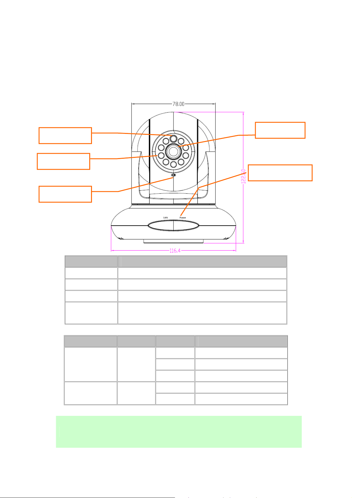
2.2.1 Identification of ICA-HM227W physical detail Front view
Light sensor
Infrared LED
Microphone
Item Description
Light sensor
Infrared LED
Microphone
Focus Ring
LED indicators
Detects light level of the place where this IP camera install.
Lights up when it’s too dark
Receives voice
Focus ring
LED indicators
LED Color State Meaning
LAN / ACT
Power LED
These LEDs can be switched off regardless the operation status of IP camera in IP
NOTE
camera’s configuration menu. This will be helpful if you don’t want other people to
know the operation status of this IP camera
If the image looks fuzzy, try to turn this focus ring clockwise or
counter-clockwise to adjust focus until the image looks clear
Blue
Blue
On Ethernet cable connected
Off Ethernet cable disconnected
Flash Transferring data
On IP camera is switched on
Off IP camera is switched off
10
Page 12
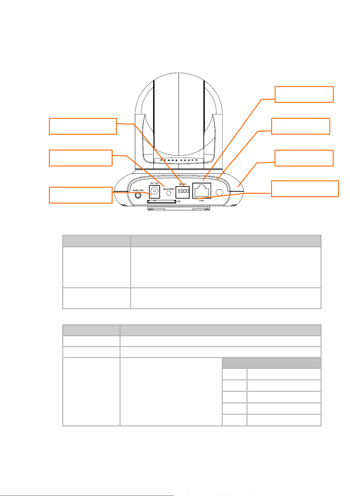
Rear Panel
DI/ DO
WPS/ Reset Button
Power Connector
Audio Connector
Button Description
Button Function
Press the WPS button and hold it for 3 seconds to enable the WPS
function, the LED will flashed very fast which means connecting. When
WPS
connect with the router, the LED flashed will be slow down means
connect successful.
Press the button and hold it for 10 second to reset the camera settings to
Reset
factory default value
LAN
Antenna Base
SD/ SDHC Card Slot
Physical
Interfaces
Connector
Power Connector The input power is 12VDC, 2A.
Audio Connector Connects to external audio amplifier to output voice. Use 3.5mm audio cable.
DI/DO
Function
Digital input / output dry contacts.
Connects to external peripherals by
wire. To insert or release a wire, press
the button of the PIN you wish to insert
or release.
DI/DO PIN ASSIGNMENT
Item
GND
DO
DI1
DI2
Description
Signal ground (Right)
Digital Output #1
Digital Input #1
Digital Input #2(Left)
11
Page 13
DO NOT CONNECT POWERED CABLE to DI/DO! This
WARNING
will damage the device permanently!
Connector
LAN Connect to your local area network by Ethernet cable.
Antenna Base Allows device connects to the supplied antenna.
SD/ SDHC Card Slot
Function
Inserts SD card for video recording. Maximum 32GB** of SDHC card
supported.
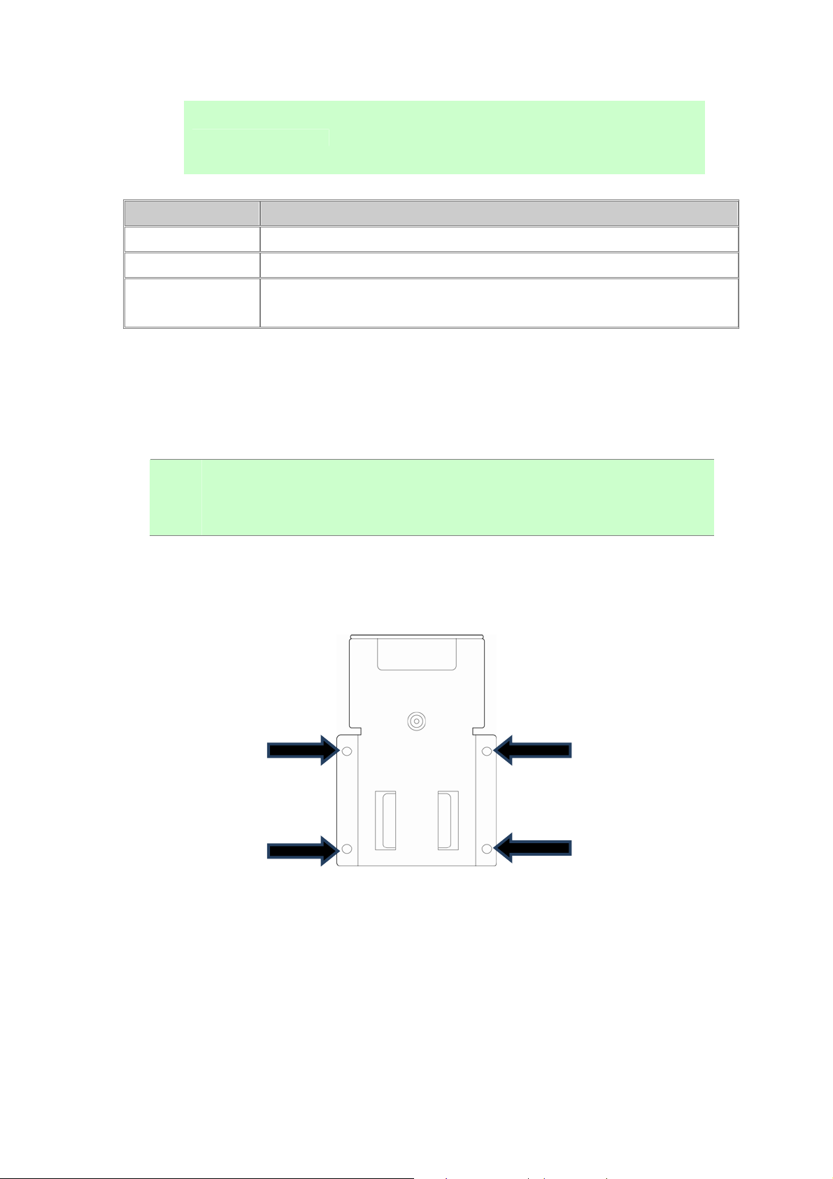
2.3 Hardware Installation
Please follow the following instructions to setup your new IP camera.
"
NOTE
1.Secure the wall mounting metal plate A on the wall, secure it by 4 screws at the screw holes
indicated by black arrows. You can secure it upside-down when required.
If you wish to place this IP camera on the table, please skip step 1 to 5.
2.Insert wall mounting metal plate B into the slot at the bottom of this IP camera by the
direction i ndicated by black arrow.
12
Page 14
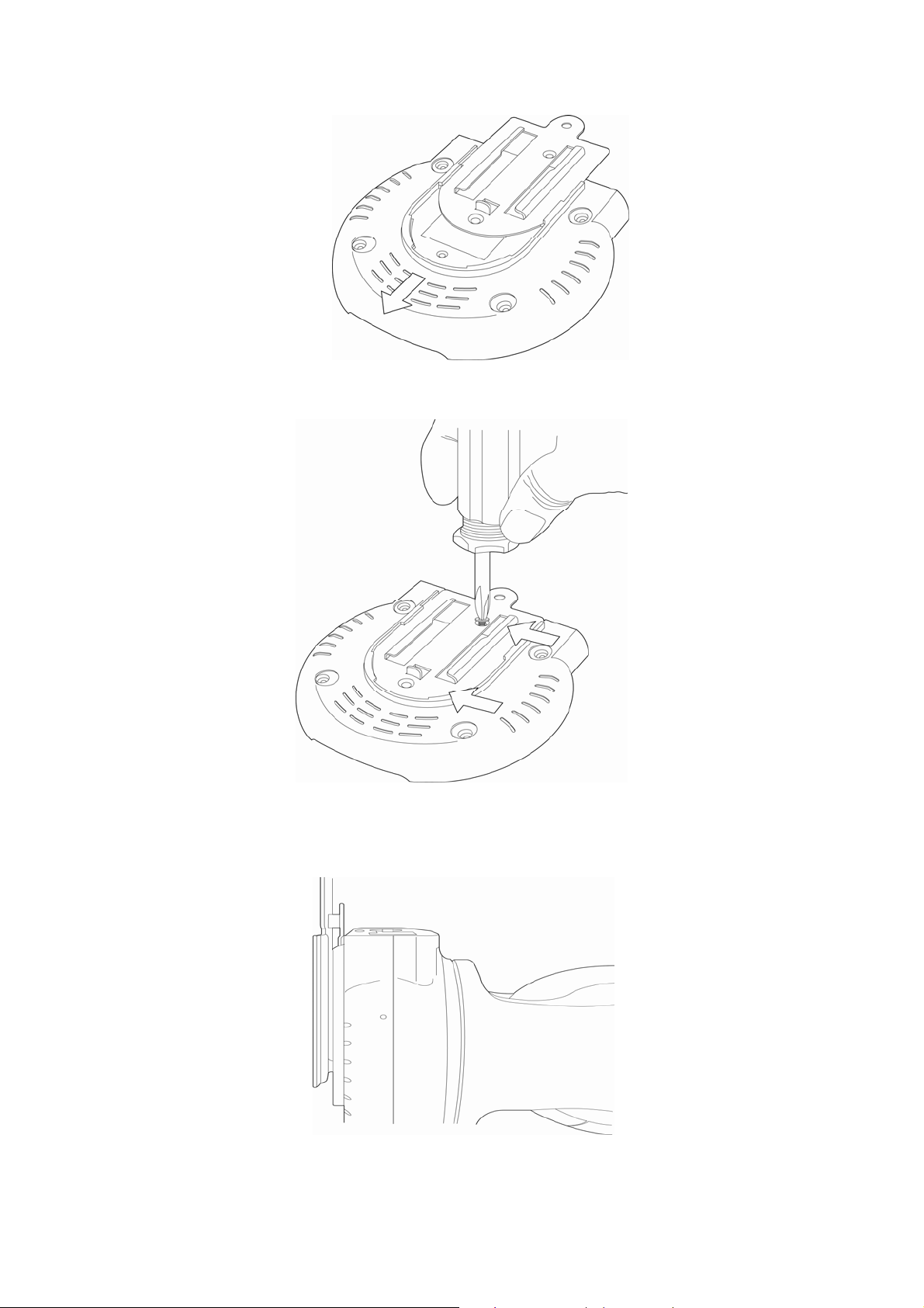
3. Secure wall mounting metal plate B by 2 screws.
4.Insert the IP camera (with wall mounting metal plate B installed) into wall mounting metal
plate A, which is already secured on the wall.
5.Secure the IP camera on the wall by securing wall mounting metal plate A and B together by
13
Page 15

screw at the place indicated by black arrow.
6.When mounted on the wall, cables can pass through wall mounting metal plate A as
indicated by the picture below.
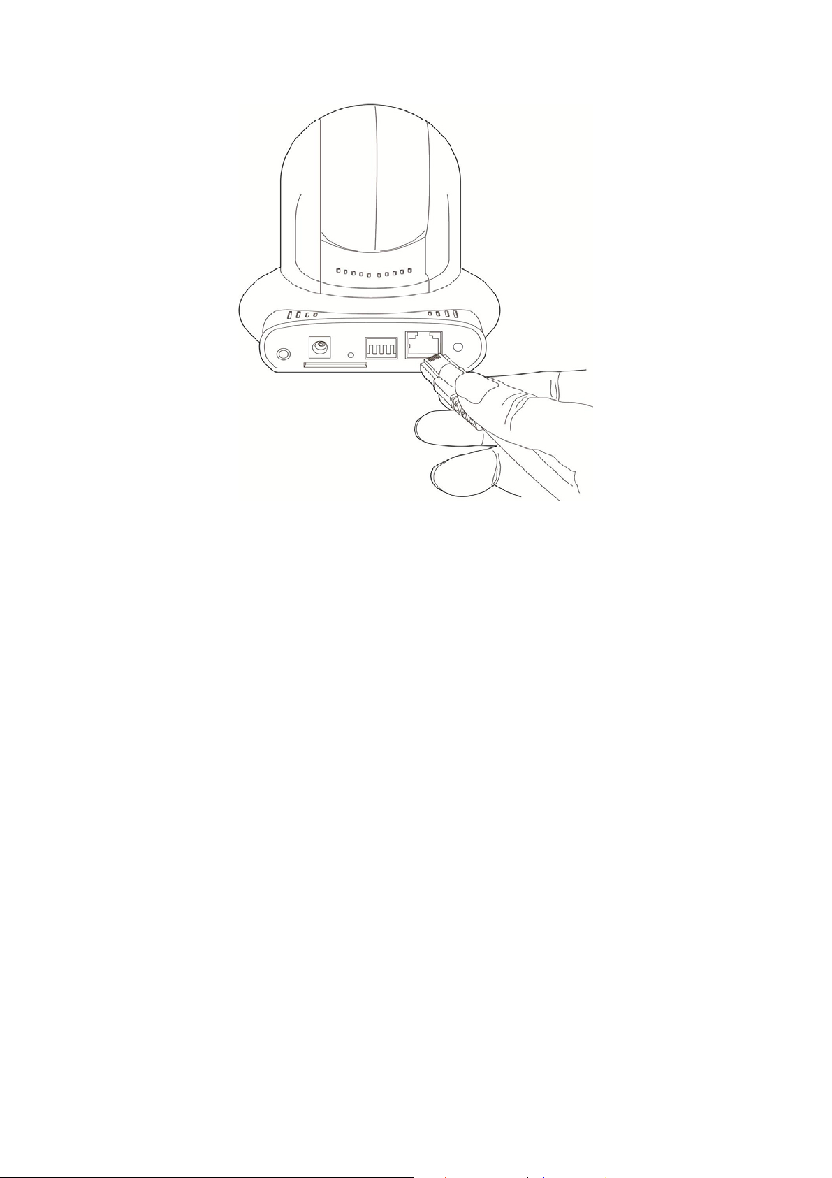
7.Insert Ethernet cable to the Ethernet port of this IP camera for Ethernet connection.
14
Page 16
15
Page 17

8.Insert DI/DO signal cable(s) into DI/DO port of this IP camera. If you don’t have DI/DO
accessories, you can skip this step.
9.Insert AC power adapter’s cable into DC12V port of this IP camera.
10.The LED lights should light up after few seconds, and the IP camera will test its Pan/Tilt
motor within 1 minute (Do not disturb IP camera at this stage). Please refer to following
16
Page 18
chapters for detailed operating instructions.
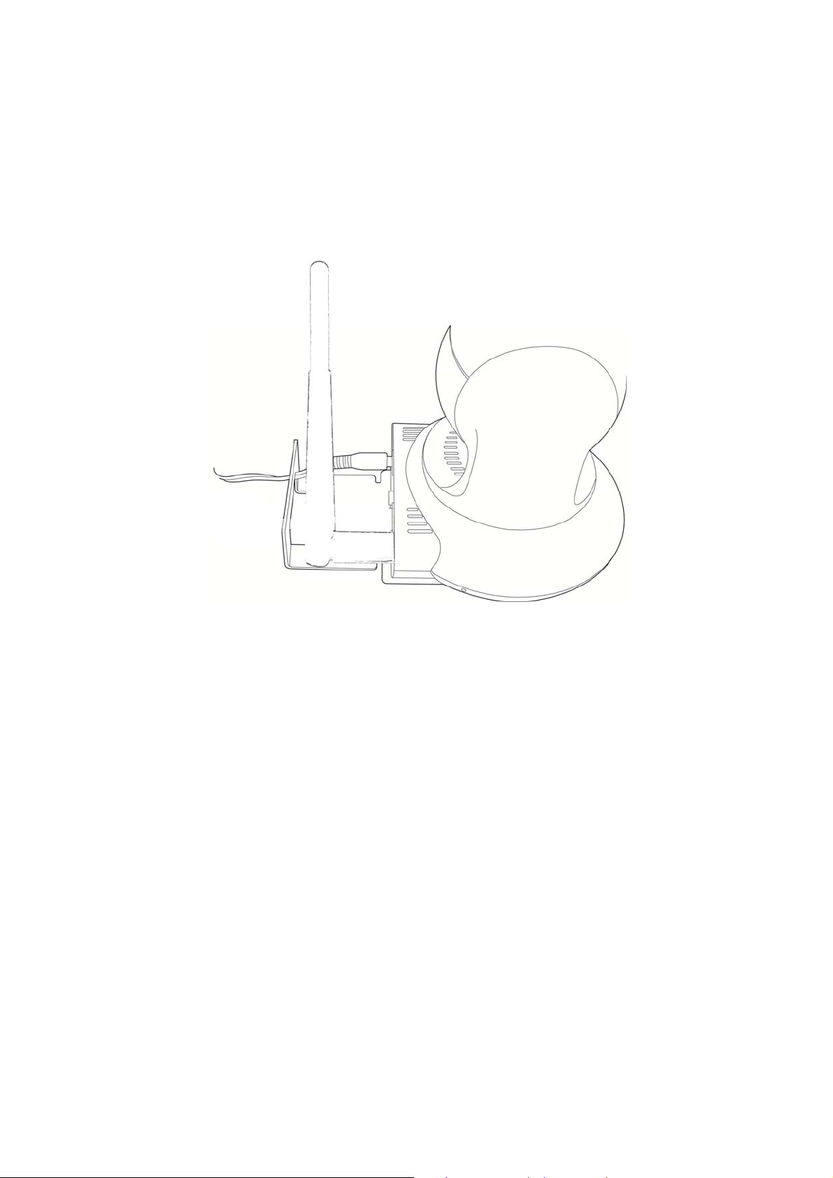
11.If it needs to set up wireless connection, please attach the wireless antenna to the IP
camera and configure through wired connection. Remove the network cable after finish all
relative wireless configuration then user can access the camera through wireless connection.
Please refer to the section 3 for detail configuration.
17
Page 19
2.4 Initial Utility Installation
This chapter shows how to quick set up your IP Camera. The IP Camera is with the default
settings. However to help you find the networked IP Camera quickly the Windows utility
(PLANET IPFinder) can search the IP Cameras in the network that shall help you to configure
some basic setting before you start advanced management and monitoring.
Please insert the bundle CD disk into your CD/DVD-ROM drive. When the welcome web page
appears, please click your IP Camera name on the IP Camera list i.e. ICA-HM227W. Then
click on the utility IPFinder to start the program.
2.5 Preparation
You can use your new Network IP Camera by its web user interface via web browser. Currently
the viewing system requirement for Network IP camera is:
■ OS: Microsoft Windows 2000, 2003, 2008 server, XP, Vista, Win7
■ Browser: Mozilla Firefox, IE7 or above, Chrome, Safari
■ Cell phone: 3GPP player
■ Quick Time: 6.5 or above
The IP Camera will use DHCP server on your local network to obtain an IP address
automatically by default. So, you can check your DHCP server’s IP address lease table to find
the IP address of IP Camera.
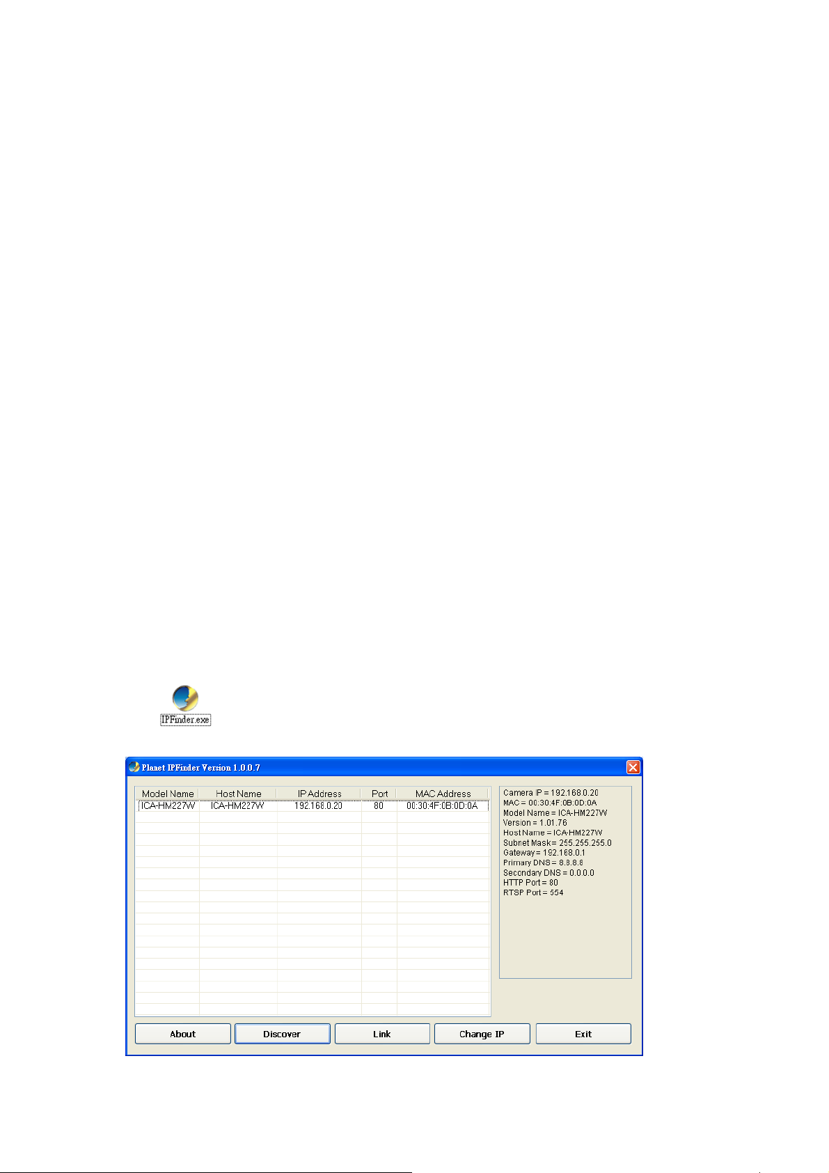
2.5.1 Configure Network by PLANET IPFinder
1. Use “IP Finder” to assign an IP address of IP CAMERA.
The IP Finder software is in the attached CD named" IPFinder.exe ".
2. The GUI of IP Finder is as follows (Default IP: 192.168.0.20).
18
Page 20
3. Press ‘Discover’ button to search for all IP Cameras on your local network (make sure all IP
Cameras are powered on and connect to local network first). When you find any IP Camera,
you can click on it and click ‘Link’ button to connect to it by your web browser.
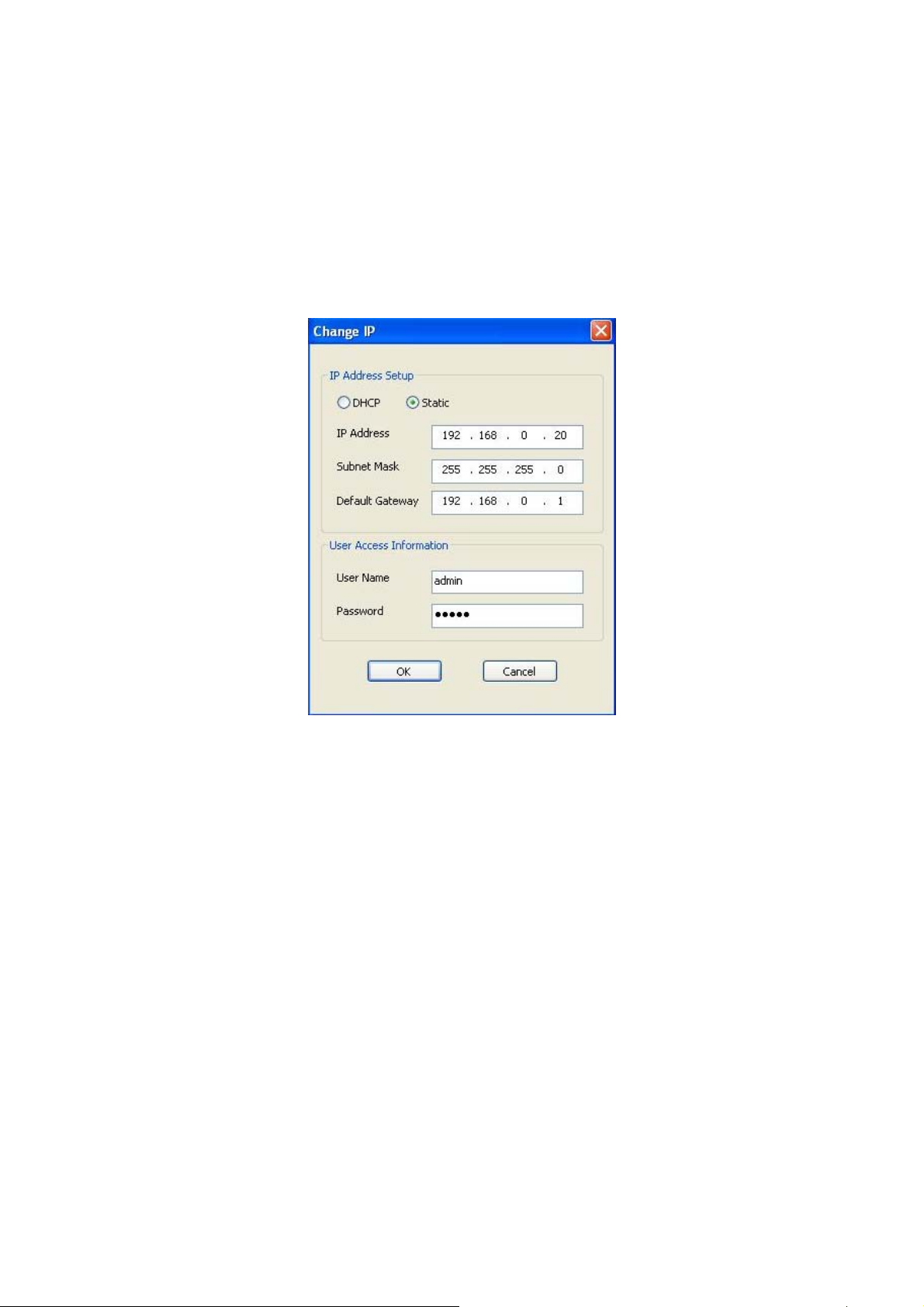
4. If you need to change a certain IP Camera’s IP address, you can also click on the IP
Camera you wish to change IP address, then click ‘Change IP’ button to change select IP
Camera’s IP address setting.
5. Please make sure the subnet of PC IP address and IP CAM IP address are the same. If you
no longer need to use this utility, click ‘Exit’ button to close it.
19
Page 21
2.6 Setup ActiveX to use the Internet Camera
The Internet Camera web pages communicate with the Internet Camera using an ActiveX
control. The ActiveX control must be downloaded from the Internet Camera and installed on
your PC. Your Internet Explorer security settings must allow for the web page to work correctly.
To use the Internet Camera, user must setup his IE browser as follows:
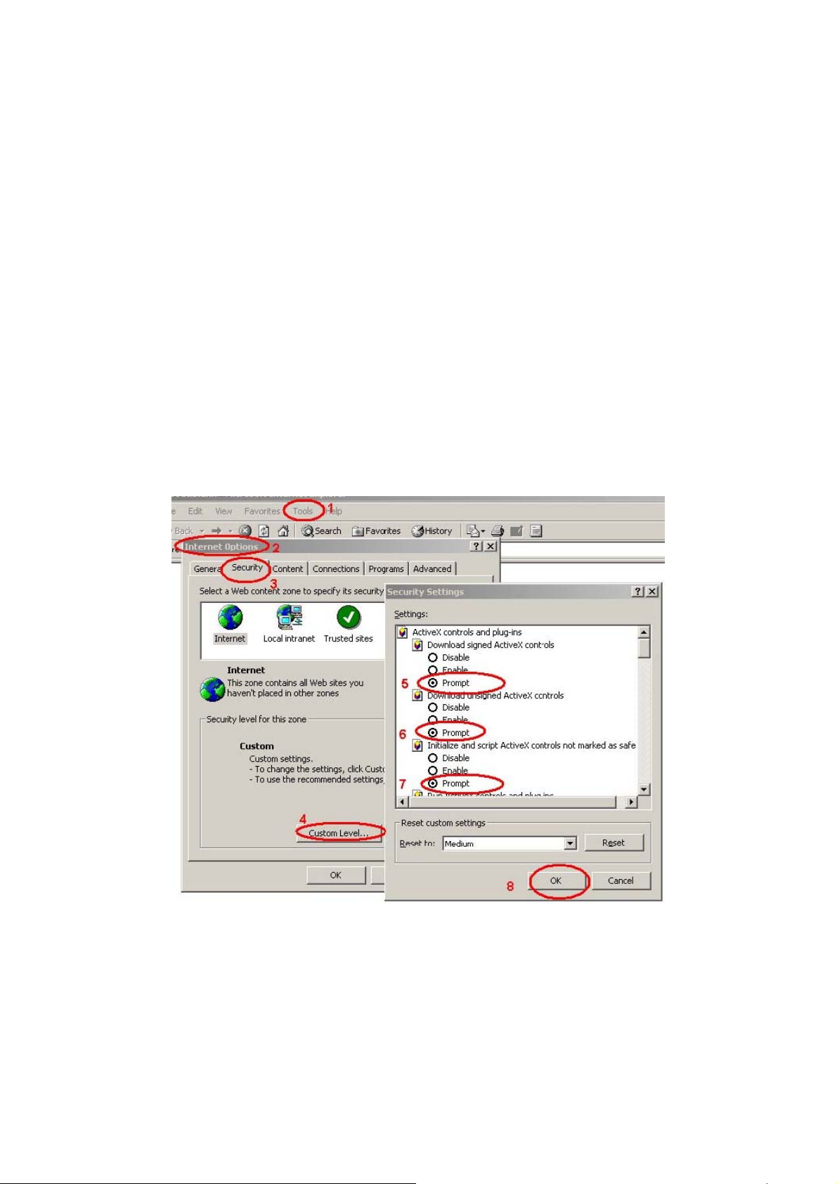
2.6.1 Internet Explorer 6 for Windows XP
From your IE browse Î ”Tools” Î ”Internet Options…” Î ”Security” ΔCustom Level…”,
please setup your “Settings” as follow.
Set the first 3 items
• Download the signed A ctiveX co ntrols
• Download the unsigned ActiveX controls
• Initialize and script the ActiveX controls not masked as safe to Prompt
By now, you have finished your entire PC configuration for Internet Camera.
20
Page 22
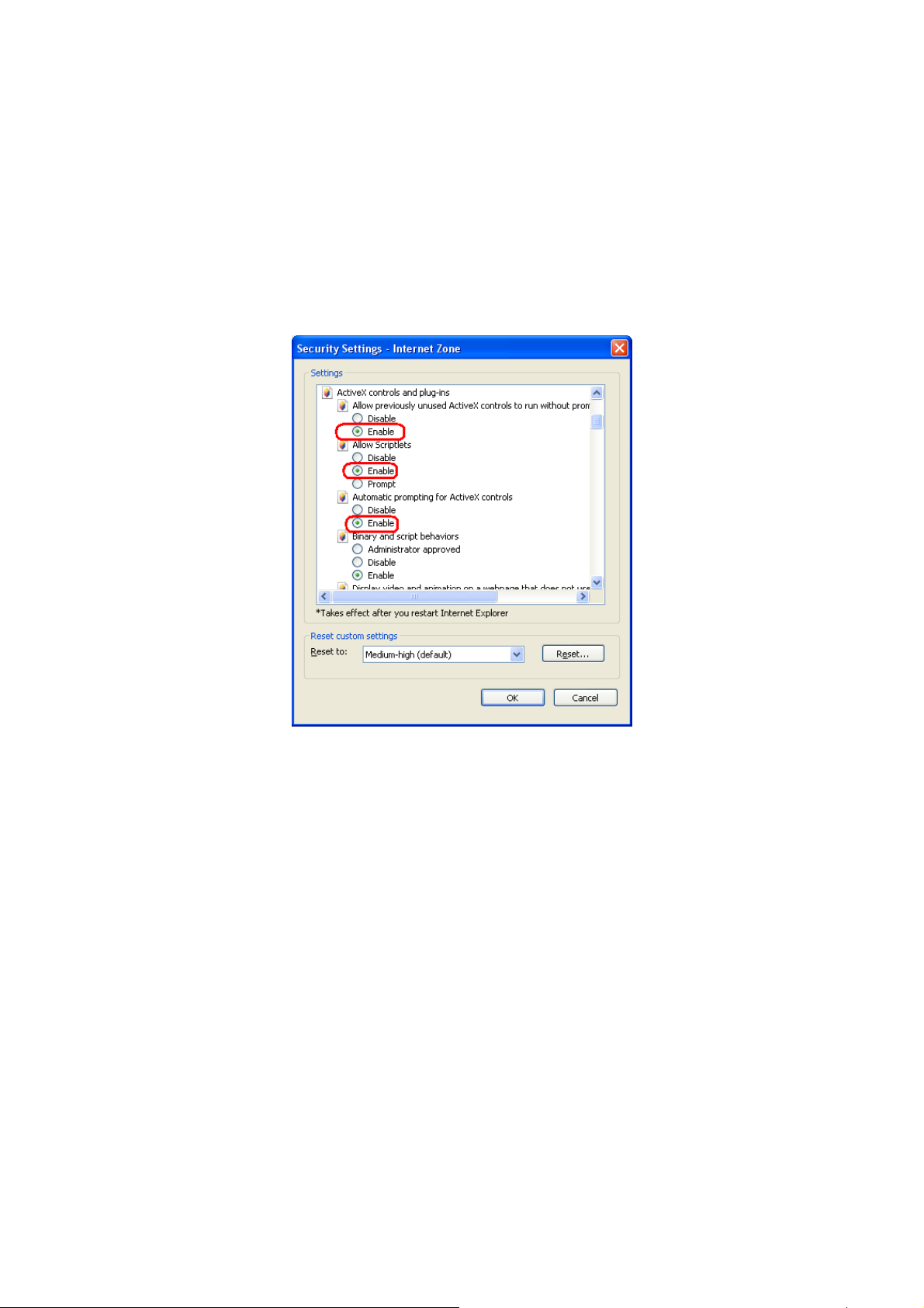
2.6.2 Internet Explorer 7 for Windows XP
From your IE browse Î ”Tools” Î ”Internet Options…” Î ”Security” ΔCustom Level…”,
please setup your “Settings” as follow.
Set the first 3 items
• Allow previously unused ActiveX control to run…
• Allows Script lets
• Automatic prompting for ActiveX controls
By now, you have finished your entire PC configuration for Internet Camera.
21
Page 23
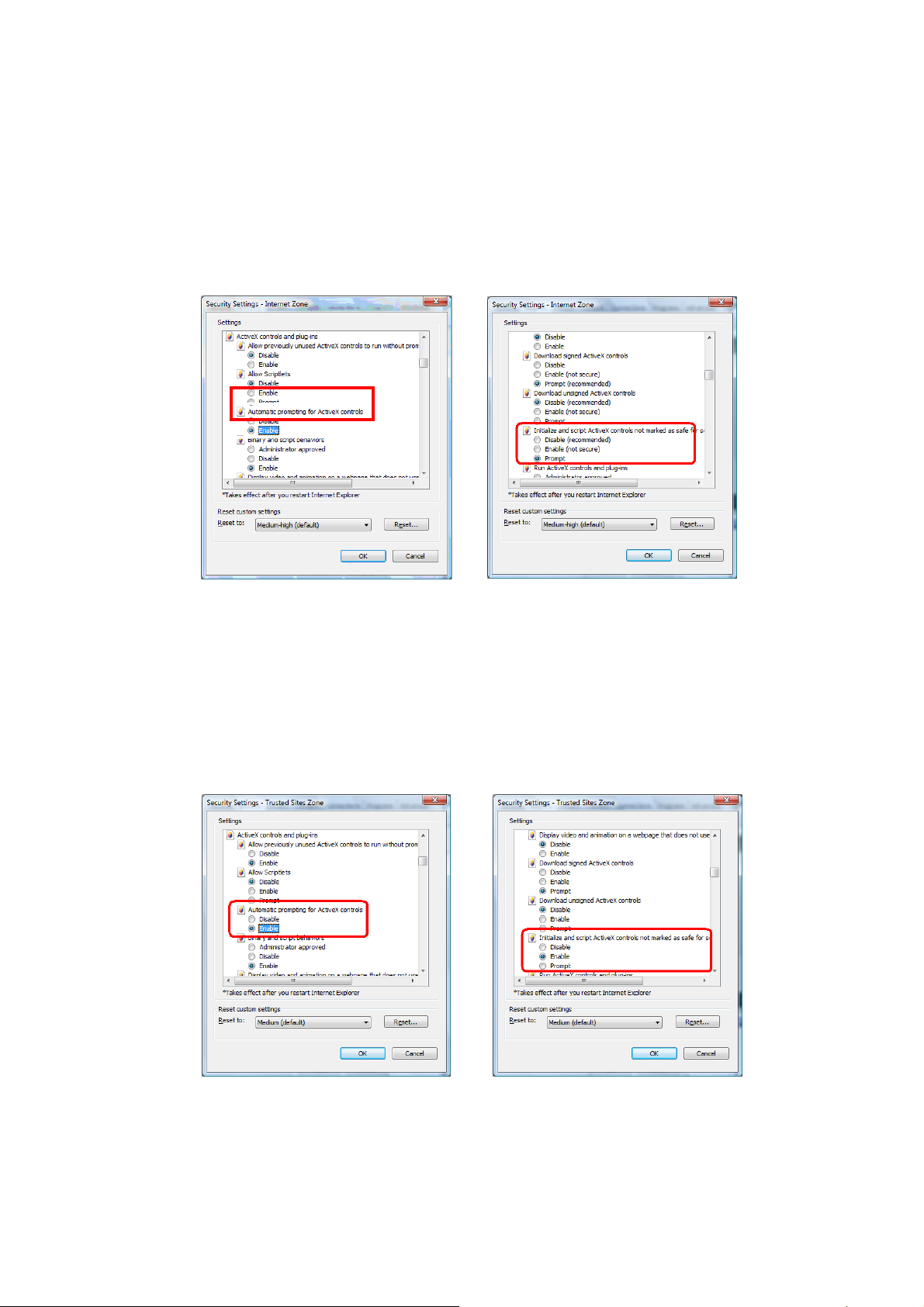
2.6.3 Internet Explorer 7 for Windows Vista
From your IE browse Î ”Tools” Î ”Internet Options…” Î ”Security” Î ”Internet” ΔCustom
Level…”, please setup your “Settings” as follow.
• Enable “Automatic prompting for ActiveX controls”
• Prompt “Initialize and script active controls not marked….”
From your IE browse Î ”Tools” Î ”Internet Options…” Î ”Security” Î ”Trusted Sites”
ΔCustom Level…”, please setup your “Settings” as follow.
• Enable “Automatic prompting for ActiveX controls”
• Prompt “Initialize and script active controls not marked….”
By now, you have finished your entire PC configuration for Internet Camera.
22
Page 24
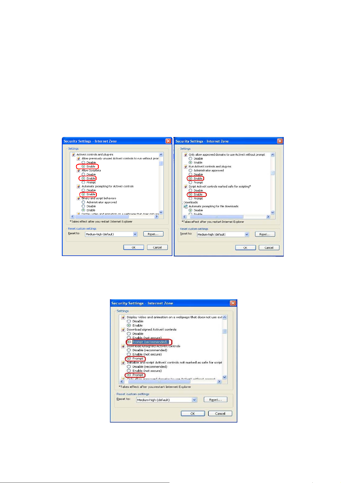
2.6.4 Internet Explorer 8 for Windows XP
From your IE browse Î ”Tools” Î ”Internet Options…” Î ”Security” ΔCustom Level…”,
please setup your “Settings” as follow. Set the first some items as below.
Under ActiveX ensure the following are set to enabled
• Allow previously unused ActiveX control to run…
• Allows Script lets
• Automatic prompting for ActiveX controls
•
Run ActiveX and plug-ins
•
Script ActiveX controls marked as safe for scripting
Set the following to “Prompt”
• Download unsigned ActiveX Control
• Download Signed ActiveX Control
• Initialize and script ActiveX controls not mark as safe
By now, you have finished your entire PC configuration for Internet Camera.
23
Page 25

2.7 Using UPnP of Windows XP or Vista
2.7.1 Windows XP
UPnP™ is short for Universal Plug and Play, which is a networking architecture that provides
compatibility among networking device, software, and peripherals. This device is an UPnP
enabled device. If the operating system, Windows XP, of your PC is UPnP enabled, the
Internet Camera will be very easy to configure. Use the following steps to enable UPnP
settings only if your operating system of PC is running Windows XP.
"
Windows 2000 does not support UPnP feature.
NOTE
Go to Start > Settings, and Click Control Panel
The “Control Panel” will display on the screen and double click “Add or Remove Programs”
to continue
24
Page 26

The “Add or Remove Programs” will display on the screen and click Add/Remove Widows
Components to continue.
The following screen will appear, select “Networking Services” and click “Details” to continue
25
Page 27

The “Networking Services” will display on the screen, select “Universal Plug and Play” and
click “OK” to continue.
Please click “Next” to continue
26
Page 28

The program will start installing the UPnP automatically. You will see the below pop-up screen,
please wait while Setup configures the components.
Please click “Finish” to complete the UPnP installation
Double-click “My Network Places” on the desktop, the “My Network Places” will display on
the screen and double-click the UPnP icon with Internet Camera to view your device in an
internet browser.
27
Page 29

2.7.2 Windows Vista
UPnP™ is short for Universal Plug and Play, which is a networking architecture that provides
compatibility among networking device, software, and peripherals. This device is an UPnP
enabled device. If the operating system, Windows Vista, of your PC is UPnP enabled, the
Internet Camera will be very easy to configure. Use the following steps to enable UPnP
settings only if your operating system of PC is running Windows Vista.
Go to Start > Control Panel > Network and Internet > Network and Sharing Center, and
turn on “Network Discovery”.
Double-click “My Network Places“ on the desktop, the “My Network Places” will display on the
screen and double-click the UPnP icon with Internet Camera to view your device in an internet
browser.
28
Page 30

3. Web-based Management
This chapter provides setup details of the Internet Camera’s Web-based Interface.
3.1 Introduction
The Internet Camera can be configured with your Web Browser. Before configure, please
make sure your PC is under the same IP segment with Internet Camera.
3.2 Connecting to Internet Camera
z Use the following procedure to establish a connection from your PC to the camera.
z Once connected, you can add the camera to your Browser’s Favorites or Bookmarks.
Start the web browser on the computer and type the IP address of the camera. The Default IP:
“ http://192.168.0.20
“
After connected to IP Camera, it will prompt for User Name and Password, please enter
admin/admin to continue Web Management. Confirm the installation as it is required to view
the video stream and some operations.
29
Page 31

If difficulty is met, please refer to the following steps to establish the connection:
- The IP Camera must be installed and powered ON.
- If the IP Camera’s default IP Address (192.168.0.20) is already used by another device,
the other device must be turned OFF until the device is allocated a new IP Address
during configuration.
"
If the User name and Password have been changed with PLANET IPFinder,
NOTE
When you know the IP address of IP Camera, you can connect to it by Internet Explorer web
browser by entering its IP address in address bar. The use login screen will appear when you
get connected:
IP Camera’s administrator username and password are both ‘admin’ (lower case) by default.
Click ‘OK’ button or press ‘ENTER’ key on your keyboard when you finish entering username
and password.
please enter the new User name and Password here.
When you connect to IP Camera for the first time, you’ll see the following message. This
message prompts you that you need to install ActiveX plugin before you can see the video
from IP Camera.
For IE 8 and earlier version:
Right click the indication bar and click:
‘‘Install This Add-on for All Users on This Computer…’ to install ActiveX plugin.
For IE 9:
Click ‘Allow’ button located at the bottom of IE to install ActiveX plugin.
30
Page 32

If you’re prompted that:
‘Windows Firewall has blocked some features of this program’
Click ‘Allow access’, or IP Camera will not be able to function properly.
When you’re installing Internet Explorer plugin, you may also be prompted that if you want to
allow changes to be made to your computer:
Click ‘Yes’ to allow changes.
31
Page 33

After ActiveX plugin is installed, you should be able to see the video stream from camera.
"
NOTE
If this is the first time you use this IP Camera, you can refer to chapter 2.4 for
instructions on Setup Wizard, which will guide you to complete the software setup
of your new IP Camera.
32
Page 34

3.3 Viewing Live Video
After ActiveX control is installed, you can view IP camera’s video by web browser. Just connect
to IP camera by web browser and login, and then you can see live video from IP camera:
There are various controls on web page; here are descriptions of every control item:
Item Description
‘Home’ button This button is visible in all setup pages of IP camera, and you
can go back to live video view by clicking this button when
you’re in other page.
Stream
Digital Output
(ON / OFF)
Client Settings
Configuration
Language Open language menu, you can switch web interface to other
Select video stream type: H.264 or MJPEG. H.264 required
less network bandwidth and this will help when network
connection is slow.
Switch digital output interface on or off.
Open ‘Client Setting’ menu.
Open ‘Configuration’ menu.
language.
Available languages: English, Simplified Chinese,
Original size /
Fit screen
Traditional Chinese
Switches live image view between original size (full size: 3M
pixels) and fit screen (smaller size).
33
Page 35

If you want to see video in detail, switch to original size. If your
computer monitor’s resolution is not enough and you want to
/
see full image view, switch to fit screen and image size will
adjust automatically.
‘Connect’ button
Start live video view.
‘Disconnect’ button
Stop live video view.
‘Snapshot’ button Take a snapshot or camera video and save image file on your
computer. When you click this button, a new window will
appear:
‘Start Video Record’
button
‘Enable Digital Zoom’
button
Click ‘Save’ button when you see the image you wish to save,
and you’ll be prompted to indicate the folder on your computer
to save image file. If you changed your mind and don’t want to
save image file, click ‘Cancel’.
Click this button to record video and save video file on your
computer. You’ll be prompted to indicate the folder on your
computer to save video file.
This function will enlarge video view digitally from 1X to 10X,
so you can see objects in video in detail.
34
Page 36

Enable / Disable mute
button
That digital zoom uses computer algorithm to
"
NOTE
When mute is enabled (
IP camera; If you want to hear voice from IP camera, click this
enlarge the video and some details may lost. If
you need to focus on detail of specific objects in
video view, please use optical zoom ring on lens
set of IP camera.
), you will not hear the voice from
/
Start / Stop talk
Button
/
button to disable mute (
You can drag the slide bar (
enable/disable mute button to adjust audio playback volume.
Start or stop playing your voice through IP camera’s audio
output. When talk is stopped, people at IP camera will not
hear you.
You need a microphone connected to your
"
NOTE
computer, and computer’s mixer setting must
enable microphone recording, or nothing will be
outputted by IP camera.
).
) beside
35
Page 37

3.4 Client Settings
In ‘Client Settings’ menu, you configure basic IP camera settings like data transfer protocol
and data storage folder.
To access ‘Client Settings’ menu, click ‘Client Settings’ button on the left.
The following screen will appear:
Here are the descriptions of every setup item:
36
Page 38

Item Description
RTSP Select this option to use RTSP (Real-Time Streaming Protocol) to
transfer video data.
HTTP Select this option to use HTTP (Hyper-Text Transfer Protocol) to
transfer video data.
If you don’t know which one you should use, select ‘RTSP’.
Folder Select a folder on your computer to save recorded video. Click
‘Browse’ button and you’ll be prompted to select a folder.
Prefix
When saving video files, the characters you typed in ‘Prefix’ field will be
used as leading characters of video file’s name.
For example, the default setting of ‘Prefix’ is ‘CLIP’, and video file’s
named will be ‘CLIPxxxx’, where xxxx is a 4-digit serial number.
Add date and
time suffix to file
name
Check this box to add data and time to the ending part of video file’s
filename, so you can see the date and time the video file is created
directly from its filename.
When you finish with above settings, click ‘Apply’ button to save change
37
Page 39

4. Advanced Configuration
If you wish to configure IP camera’s settings, you can access IP camera’s ‘Configuration’ menu,
which provides various kinds of system setting.
To access configuration menu, click ‘Configuration’ button on the left.
The ‘Configuration’ submenu will appear, please pick a setup item you wish to configure.
38
Page 40

4.1 System
In this menu, you can configure basic IP camera settings like hostname and time.
Here are the descriptions of every setup item:
39
Page 41

Item Description
Host Name Input the IP camera’s hostname here, it can be any meaningful
words or characters that will help you to identify this IP camera.
You can use IP camera’s installation location as host name, and
this will help you to identify IP camera when you have many IP
cameras installed.
Indicator LED The LED lights located at the back of IP camera is switched on
by default. But, if you don’t want other people to know the
status of this IP camera (so they will know this IP camera is
operating etc.), you can select ‘Off’ and LED lights will be
switched off.
Time Zone Select the time zone of residence from dropdown menu to keep
correct date and time.
Daylight Saving If the area you live uses daylight saving, check this box;
otherwise do not check this box to keep time correct.
Keep the current date
and time
Select this option and date / time setting will not be changed
when you click ‘Apply’ in the page.
You can check ‘Camera Date and Time’ item in this page to
know IP camera’s current date and time setting.
Synchronize with
computer time
Synchronize with NTP
Server
Select this item and IP camera will use your computer’s time as
its time.
Select this item and IP camera will keep its date and time
setting synchronized with specified time server (NTP server).
Please input NTP server’s IP address or host name in ‘NTP
Server Address’ field, and select time update interval from
‘Update Interval’ dropdown menu.
That digital zoom uses computer algorithm to
enlarge the video and some details may lost. If yo u
NOTE
need to focus on detail of specific objects in video
view, please use optical zoom ring on lens set of IP
camera.
Set Manually Set IP camera’s date and time manually. Please set current
date and time by ‘Date’ and ‘Time’ dropdown menu.
When you finish with above settings, click ‘Apply’ button to save changes.
40
Page 42

4.2 Security
In this menu, you can configure IP camera’s login account.
There are three kinds of account:
‐ Administrator : Can view IP camera’s video and make changes of camera setting
‐ User : Can view IP camera’s video and see LOG, and change Client Setting and
language
‐ Guest : Can view IP camera’s video , and change language
There can be multiple users, but only one administrator is allowed, and you can’t change
administrator’s user name (it will always be ‘administrator’).
Here are the descriptions of every setup item:
Item Description
Password / Retype Input administrator’s new password in both ‘Password’ and
4142
Page 43

Password
‘Retype Password’ field, and click ‘Modify’ button to change
(Administrator)
Account List Here lists all users existed in IP camera. If you want to remove
User Name Input new user’s username here. User name must be greater
Password / Retype
Password
Authority
administrator’s password.
"
NOTE
one user, click it in the list, and then click ‘Remove’ button.
If no user is existed, ‘New Account’ message will be shown
here.
than 1 character and less than 32 characters.
Input this user’s password in both ‘Password’ and ‘Retype
Password’ field.
To define this user’s access privilege, select ‘User’ or ‘Guest’
in dropdown menu.
When you finish inputting new user’s information, click ‘New’
Don’t forget administrator’s password! Or you’ll
need to reset IP camera’s all settings to get
administrator’s password recovered.
button to create a new user.
Page 44

4.3 Network
4.3.1 General
In this menu, you can configure IP camera’s network setting. This IP camera supports both
IPv4 and IPv6 IP address.
Here are the descriptions of every setup item:
Item Description
LAN Select this option to assign an IP address to LAN port (or obtain an
address from DHCP server automatically).
Available options are:
‐ DHCP IPv4: Obtain an IPv4 IP address from DHCP server on LAN
automatically.
4344
Page 45

‐ DHCP IPv4 / IPv6: Obtain both IPv4 and IPv6 address from DHCP
server on LAN automatically.
‐ Static IPv4 / IPv6: Assign an IPv4 / IPv6 address to IP camera
manually. If you don’t have a DHCP server on your local area
network, you must use this option to specify an IP address.
IP Address(IPv4): Input IPv4 IP address*
IP Address(IPv6): Input IPv6 IP address*
Prefix Length: Input IPv6 IP address’ prefix length (0-128)
Subnet Mask: Input subnet mask
Gateway: Input gateway address
Primary DNS: Input DNS server’s IP address
Secondary DNS: Input backup DNS server’s IP address, you
can leave this field blank.
*You can leave this field blank, if you only wish to use IPv4 or
IPv6 IP address.
‐ Enable UPnP Discovery: Check this b ox to enable other devices on
network to discover the presence of this IP camera by UPnP. It’s
recommended to enable this function.
‐ Enable UPnP Port Mapping: When UPnP is enabled, check this box
to enable UPnP’s port mapping.
PPPoE Select this option to use PPPoE to connect to network. You have to input
PPPoE username and password assigned by network operator to get
connected.
HTTP Port Input IP camera’s web connection port number here. When this port
number is changed, you need to change web browser’s port number you
used to connect to IP camera.
For example, IP camera’s IP address is 192.168.1.1, and if you changed
HTTP port number to 82, please input ‘http://192.168.1.1:82’ in web
browser’s address bar to access IP camera’s web configuration interface.
RTSP Port Input RTSP port number. When this port number changes, you must
change corresponding settings in external network devices (NVR or CMS
software) so they can receive this IP camera’s video.
RTP Data Port Input RTP data port number here.
When you finish with above settings, click ‘Apply’ button to save changes.
Page 46

4.3.2 Advanced
In this menu, you can configure IP camera’s advance network setting.
Here are the descriptions of every setup item:
Item Description
Multicast Enable video multicast:
Multicast Group Address: Input multicast group address here, must be an address between
232.0.0.0 to 232.255.255.255.
Multicast video port: Input port number for video multicast here.
Multicast RCTP video port: Input port number for RCTP video here.
Multicast audio port: Input port number for audio here.
45
Page 47

Multicast RCTP audio port: Input port number for RCTP audio here.
Multicast TTL: Input TTL value for multicast here.
Bonjour If you’re using Mac OS and you have Bonjour installed, you can use it to discover this IP
camera.
QoS Enable QoS to improve the data transfer priority of this IP camera (Your local area network
must support QoS).
You can select Video / Audio’s QoS DSCP value (0 to 63), or both video and audio.
DDNS Enable DDNS support if your ISP assigns dynamic IP address to you. You must register a
dynamic IP service first. Currently this IP camera supports Planet DDNS, DynDNS and TZO
dynamic IP service.
Provider: Select dynamic IP service provider.
Host Name: Input the host name you obtained from dynamic IP service provider.
User name: Input user name used to login dynamic IP service provider.
Password: Input the password used to login dynamic IP service provider.
HTTPS
Check ‘Enable HTTPS’ box to enable HTTPS channel to encrypt transferred data. You can
also define HTTPS port number in ‘HTTPS Port’ field if you don’t want to use default value
‘443’.
When you finish, click ‘Apply’ to save changes.
46
Page 48

4.3.3 Wireless
In this menu, you can configure IP camera’s wireless network setting.
The descriptions of every setting in this menu will be given below:
Item Description
Wireless Connection
Network Type Select the network type of wireless connection.
Available Networks Here shows all wireless access points found by this IP camera. Please
Select “Enable” to activate wireless network function of this IP
camera, select ”Disable” to disable it.
Infrastructure :Connect the IP camera to a wireless access point
Adhoc :This IP camera will become a stand-alone wireless network
point, other wireless computers / devices can discover this IP camera
and connect to it without wireless access point.
note not all access points will be displayed at the same time, if the
access point you expected to connect does not appear, you may have
to click “Refresh” button for several times until it appears.
The description of all fields is listed below:
Connect: You can select the wireless access point you wish to
connect here.
SSID: the SSID of all found wireless access points will be shown here.
Some wireless access point may hide their SSID; in this case, you
have to identify them by their MAC address.
MAC Address: If you there are many wireless access points in
proximity or some wireless access point hides it’s SSID, you can use
MAC address to distinguish them.
Signal: Shows the radio signal strength in percent.
47
Page 49

Channel: Shows the radio channel of this wireless access point.
Encryption: Shows the encryption type used by this wireless access
point. You must use the same encryption type if you wish to connect to
a certain wireless access point. If the wireless access point does not
use encryption, “Disabled” will be displayed here.
Network Type: Shows the network type of a certain wireless access
point (Infrastructure or Adhoc).
Item Description
SSID Input the SSID of the wireless access point you wish to connect. It
should be less than 32 alphanumerical characters. When you select a
wireless access point above, it’s SSID will be filled in this field
automatically.
However, if the SSID is not displayed (the wireless access point you
selected choose to hide it’s SSID), you have to know it’s SSID and
input it here, or you will not be able to connect it.
Channel Select the radio channel you wish to use here. When network type is
‘Infrastructure”, the radio channel is auto-selected according to the
channel that wireless access point uses. You can only select the
channel number when network type is “Adhoc”.
Authentication It includes None, Open System, Shared Key 64bits and 128bits,
WPA-PSK, WPAS-PSK. Select one of them then the relative items
48
Page 50

below will transfer gray scale to black scale. Configure the setting
consistent with the setting on the wireless router/AP that this IP
camera will join the wireless network. Apply the settings then check
the wireless networking.
Item Description
Pin Code Here displays the WPS pin code used to connect to WPS-enabled
wireless access points. You have to input this number into the WPS
enabled access point to establish WPS connection.
Configure via Push
Button
Configure via Pin
Code
Click this button and this camera will enter PBC-style WPS connection
state for 120 seconds. Please push “Start PBC” button on the
wireless access point you wish to connect within 120 seconds to
establish WPS connection (The remaining time will be displayed on the
button). If connection can not be established after 120 seconds, you’ll
be prompted by a message box, and you can press “Start PBC”
button to try again.
If you have wireless access point’s WPS PIN code, you can input it
here and press “Start PIN” button to start to establish PIN-style WPS
connection.
49
Page 51

4.4 IP Filter
When this IP camera is directly connected to Internet and not protected by firewall, this
function acts like a mini built-in firewall to protect the safety of this IP camera and avoid attacks
from hackers.
Here are the descriptions of every setup item:
Item Description
Enable Filter Check this box to enable IP address filter, uncheck this Box to
disable this function.
Accepted IP list Here lists all IP address that can build connections to this IP
camera. If you want to remove a set of IP address from the list,
click on the IP address and click ‘Remove’ button.
IP Address
(Accepted IP list)
Input the starting and ending IP address of IP address you wish to
accept connections here. IP camera will only accept connections
established from these IP address.
If you want to specify one IP address only, input the same IP
5051
Page 52

address in both field. Click ‘New’ button to add IP address into
accepted IP list.
Deny IP list Here lists all IP address that cannot build connections to this IP
camera. If you want to remove a set of IP address from the list,
click on the IP address and click ‘Remove’ button.
IP Address
(Accepted IP list)
Input the starting and ending IP address of IP address you wish to
deny connections here. IP camera will deny connections
established from these IP address.
If you want to specify one IP address only, input the same IP
address in both field.
Click ‘New’ button to add IP address into deny
IP list.
When you finish with above settings, click ‘Apply’ button to save changes.
Page 53

4.5 Video
You can adjust the image of the IP camera in this menu.
There are 3 sub-menus in this menu: Image Setting, Video Setting, and Overlay, which can
be accessed by tabs on the top:
52
Page 54

4.5.1 Image Setting
You can adjust the image parameters in this page.
Here are the descriptions of every setup item:
Item Description
Brightness /
Contrast /
Saturation /
Sharpness
Default
Mirror
Control the image parameters. Click ‘ - ' to decrease value, or click ‘ +
‘ to increase value. You can also input the value in the field directly.
Set all above values to default value ‘128’.
Check ‘Vertical’ or ‘Horizontal’ box to flip the image vertically or
horizontally, this will help to correct the orientation of image when IP
camera is hanged bottom-up by camera holder. You can click both
‘Vertical’ and ‘Horizontal’ box at the same time.
5354
Page 55

Power Line
Select the frequency of power line of the place you’re using this IP
Frequency
camera. This will help to reduce the flicker of certain lights in the image.
Condition Select the condition that you’ll be using this IP camera from dropdown
menu.
‐ Auto: IP camera will adjust its parameters automatically.
‐ Night: You’ll be using this IP camera in dark places where lights are
insufficient.
TV Out
Click “Enable” box to enable its “VIDEO OUT” function for
connections and video sending to TV monitors or DVRs.
Lens(under “TV
Out”)
While connecting with an auto iris lens, and would like to have clear
images from “VIDEO OUT”, please click “Auto iris” to enable this
feature.
IR-cut An IR-cut filter is built in this IP camera to reduce the effect of IR lights
(which will change the color of image and makes it looks different than
what you see through your eye), and most of IR lights are coming from
sunlight.
You can select the behavior or IR-cut filter:
‐ Auto: IR filter will act automatically. If you don’t know if you should
use IR filter, select this option.
‐ Always ON: IR filter is always on.
‐ Always OFF: IR filter is always off.
Day IR-cut filter will only be switched on when there’s sunlight. You can
define the starting and ending time when IR-cut filter should be
switched on by select ‘Schedule’ and define starting and ending time
by dropdown menu.
When you finish with above settings, click ‘Apply’ button to save changes.
Page 56

4.5.2 Video Setting
You can adjust the video transfer parameters in this page.
Here are the descriptions of every setup item:
Item Description
H.264 /MPEG4
Video
Resolution
Select the compression of main stream: H.264 / MPEG4.
Select video resolution.
‐ H.264:
2048x1536 (QXGA) / 1920x1080 (1080p)
1280x960 (960p) / 1280x720 (720p)
720x480 (D1) / 640x480 (VGA)
320x240 (QVGA)
‐ MPEG4:
1920x1080 (1080p) / 1280x960 (960p)
1280x720 (720p) / 720x480 (D1)
640x480 (VGA) / 320x240 (QVGA)
5556
Page 57

MJPEG:
"
That some video resolution is not available when video
NOTE
Frame Rate Select video frame rate. Please note that some frame rate is not available
when video encoder is ‘H.264’.
When network speed is insufficient, select a lower frame rate will help.
encoder is ‘MPEG4’.
1280x720 (720p) / 720x480 (D1)
640x480 (VGA) / 320x240 (QVGA)
Rate Control
When you finish with above settings, click ‘Apply’ button to save changes.
"
MJPEG options are only available for portable devices like cell phone.
NOTE
Select video bit rate. You can control bit rate by both ‘Video quality’ and
‘Bit rate’:
‐ Video quality: There are 5 levels of video quality, select ‘very high’
to improve video quality but consumes more network bandwidth, and
select ‘very low’ will decrease video quality and consumes less
network bandwidth.
‐ Bit rate: Input video’s bit rate directly. It must an integer between 512
and 4000. Higher bit rate provides better video quality, but consumes
more network bandwidth.
Page 58

4.5.3 Overlay Setting
You can adjust the video overlay parameters in this page.
Here are the descriptions of every setup item:
Item Description
Enable Time Stamp Check this box to enable overlaying time stamp on video.
Remove the
background color of
the text
(for Time Stamp)
Enable Text Display Check this box to display certain text on video; this will help when
Remove the
background color of
Check this box to remove time stamp’s background color. You
may find this will help the readability of time stamp text in some
cases.
you need to identify certain IP camera when you have a lot of IP
cameras.
Please input the text in ‘Text’ field. You can input up to 15
characters.
Check this box to remove custom text’s background color. You
may find this will help the readability of text in some cases.
the text (Text)
5758
Page 59

Enable Image Overlay Check this box to overlay a specific image on video, so you can
show certain text / picture on the video and help people to identify
this IP camera.
Click ‘Browse’ button to pick a picture on your computer, then
click ‘Update’ button to use the picture. Please note that there
are certain restrictions:
‐ Select .bmp / .jpg / .jpeg image files only.
‐ Image’s resolution should be less than 160 x 128, and can be
divided by 4.
‐ Do not upload image files that size is greater than 64KB.
When you finish with above settings, click ‘Apply’ button to save changes.
Page 60

4.6 Audio
You can adjust audio input / output parameters here.
Here are the descriptions of every setup item:
Item Description
Enable Microphone Check this box to enable microphone. If you don’t want to hear voice
from IP camera, you can uncheck this box to disable it.
Audio Type The format is fixed as G.711
Microphone Gain If the voice received by microphone is too loud or silent, you can use
this function to improve voice volume, so you can hear voice from IP
camera more clearly.
‐ Select -2 or -1 dB to correct the voice that is too loud;
‐ Select 0 dB and IP camera will do nothing on the voice;
‐ Select +2 dB to +26 dB to amplify the voice.
Enable Speaker Check this box to enable speaker. If you don’t want people at IP
camera to hear you, you can uncheck this box to disable it.
Audio Type The format is fixed as G.711
When you finish with above settings, click ‘Apply’ button to save changes.
59
Page 61

4.7 Motion
This IP camera is capable to detect object’s motion, so IP camera will only record when there’s
motion and save disk storage space.
Motion detection is performed by examine the movement of objects in rectangular motion
detection area. You can define up to 3 motion detection areas.
Here are the descriptions of every setup item:
Item Description
Enable Motion
Detection
Enable
(Window 1 to
Window 3)
Check this box to enable motion detection.
Check this box to enable this motion detection window. You can
select window 1 to 3 to enable up to 3 motion detection windows.
When a motion detection window is enabled, a rectangular will
appear on camera’s view, with its title on the top.
‐ To move / resize a motion detection window:
60
Page 62

‐ Move: Use the mouse to drag the title text.
‐ Resize: Use the mouse the drag the four corners
(upper-left/right, lower-left/right) to resize it. If you only want to
adjust width or height, drag the four sidebars (top, bottom, left,
and right).
Title
(Window 1 to
Window 3)
Percentage Select the percentage of pixel change that will trigger motion
Sensitivity Select the sensitivity level that will trigger motion detection alert.
When you finish with above settings, click ‘Apply’ button to save changes
Input characters in title field to change motion detection area’s title
text so you can identify it.
Please note that you have to click ‘Apply’ button and the text will
change.
detection alert. Select a lower percentage and you can detect tiny
changes in motion detection area.
Select a higher sensitivity and you can detect tiny changes in motion
detection area.
61
Page 63

4.8 PTZ Control
In this page, you can setup PTZ Control settings like auto pan-tilt control and patrol.
Here are the descriptions of every setup item:
62
Page 64

Item Description
Pan-tilt control
Control pan-tilt of camera by click up, down, left, right and upper-left/right,
lower-left/right.
Pan Speed Adjust the pan speed. It should be an integer between 1 (slower) to 10
(faster).
Tilt speed Adjust the tilt speed. It should be an integer between 1 (slower) to 10 (faster).
Set home Click this button to set current position as home position.
Calibration To calibration its direction and focus to its “Factory Default Position”, to
ensure its preset position will be located at the correct position without
deviation after a period of usage.
Preset list This IP camera supports up to 8 preset points. You can move camera to
preset point, and camera will stop there for a specific amount of time. You
can specify up to 8 preset points.
To set a preset point:
z Move camera to the preset point you wish to set by pan-tilt control.
z Select a preset point from the list (1 to 8)
z Input a text description for this preset point (this is optional, up to 16
characters).
z Input dwelling time (0 to 30**, seconds)
z Click ‘Set’ to save current preset point.
You can click ‘GO Preset’ button to move camera to preset point, or click
‘Remove’ to clear this preset point setting.
Patrol Setting When you have 2 or more preset points, you can make camera to move
between these points, this function is called as ‘Patrol’.
To configure patrol, please setup preset points first, then select preset points
from ‘Preset list’ and click
preset point from patrol list, select it in patrol list and click
button to add it to ‘Patrol’ list; to remove a
button.
You can also adjust the order or preset points in patrol list: select a preset
point and click
When you finish, click ‘Apply’ button
or button.
63
Page 65

4.9 Event
When there’s an event, you can use this setup page to define what IP camera should do, like
send an Email or trigger digital output to activate external alarm.
There are three setup pages:
1. Setting: Define a new event and manage events.
2. Media: Define what kind of media file should be saved on designate media.
3. Event Server: Define the details of remote server.
Please refer to following chapters for detailed instructions.
64
Page 66

4.9.1 Settings
This page lists all existing events. You can click ‘Modify’ button to edit an existing event, or
‘Remove’ to delete an existing event.
To create a new even, just click “New” button to add an Event setting.
65
Page 67

To add a new event, click ‘New’ button and the descriptions of every setup item is listed below:
Item Description
Enable Setting Check this box to enable this event. If you just want to disable this
event temporarily, you can uncheck this box to keep this event and
disabling while not deleting it.
Title Input any description text for this event so you can identify it quickly.
You can use alphabets, numbers, and symbols include: !$-.@^_~
6667
Page 68

(no spaces allowed).
Motion Detection Check this box and this event will be activated when one of motion
detection window detects motion.
Digital Input
1 ~ 2
Enable Schedule
Time
Check this box and this event will be activated when digital input 1 or
2’s input signal is high or low (select from dropdown list).
Check this box and this event will be activated when designated
weekday and time is reached.
You also have to check weekday box, and select time from
dropdown list. If you select ‘Always’ as time, this event will be
activated during all the day.
Enable FTP Check this box and IP camera will save file on FTP server (refer to
‘FTP Server’ setting in ‘Event Server’ tab) when this event is
activated.
Enable EMAIL Check this box and IP camera will send an Email to designated
recipient address (refer to ‘SMTP Server ’ setting in ‘Event Server’
tab) when this event is activated.
Enable Samba
(Net Storage)
Check this box and IP camera will save file on samba server (refer to
‘Samba Server’ setting in ‘Event Server’ tab) when this event is
activated.
Enable SD CARD Check this box and IP camera will save file on SD card when this
event is activated. A working SD card must be inserted into IP
camera in advance.
Trigger digital
output for xx
second(s).
Check this box and IP camera will trigger digital out to ‘high’ state for
xx seconds when this event is activated, where ‘xx’ seconds must be
defined by the dropdown list.
Page 69

4.9.2 Media
You can define what kind of media file should be saved on designated media.
Here are the descriptions of every setup item:
Item Description
One Snapshot Save a picture file when event is triggered.
"
NOTE
H.264 Video Save a H.264 video clip. You can also select the recording length
before and / or after the time when event is triggered in ‘Pre Event’
and ‘Post Event’.
For example, if you set ‘Pre Event’ to ‘10’ and ‘Post Event’ to ‘5’,
and an event is triggered at 14:10:30, then the video file will be 15
seconds long, starting from 14:10:20 to 14:10:35.
Tips: You may want to know what happened before event is
triggered in many cases, especially when object is outside of
motion detection window.
"
NOTE
When you finish with above settings, click ‘Apply’ button to save changes.
That this function will be enabled while “MJPEG
codec” is appeared on the “Video Setting”.
If the “Pre Event” set to “0” second, the “Post Event”
cannot set to “0” second.
68
Page 70

4.9.3 Event Server
You can define the details of remote media server: FTP (File), SMTP (Email), and Samba
(File).
A Samba server can be any computer running windows operating system with network
neighbor function enabled. Many stand-alone network file server also support samba
server function.
69
Page 71

Here are the descriptions of every setup item:
Item Description
Enable FTP
Server
Check this box to enable FTP server upload.
‐ FTP Server: Input FTP server’s IP address or hostname.
‐ Port: Input FTP server’s port number. In most cases it should be
default value ‘21’.
‐ User Name: Input FTP server’s username.
‐ Password: Input FTP server’s password.
‐ File Path Name: Input the path where you want to save file on FTP
server, like ‘upload/record’. If you want to save file on this FTP
user’s home directory, you can leave this field blank.
‐ Enable Passive Mode: Check this box to force IP camera to
communicate with FTP server in passive mode (Some FTP Server
may only work when you check this box, while others don’t).
‐ Test FTP: Click this button to test FTP server settings above
immediately.
SMTP Server Check this box to enable Email send.
70
Page 72

‐ SMTP Server: Input SMTP server’s IP address or hostname.
‐ Port: Input SMTP server’s port number. In most cases it should be
default value ‘25’.
‐ Sender Email Address: Input the sender’s email address that will
appear in the Email send by IP camera. This will help you to identify
the Email sent by this IP camera, and may help when you have
anti-spam software installed (you can set this Email address to
‘White List’ in your anti-spam software)
‐ Receiver #1 Email Address: Input primary recipient’s Email
address. This field is required.
‐ Receiver #2 Email Address: Input backup recipient’s Email
address. This field is optional.
‐ Subject: Input Email titles that will appear in the Email send by IP
camera. This will help you to identify the Email sent by this IP
camera.
‐ Authentication: Check this box when authentication is required by
the Email server you’re using. You also need to input Email server’s
username and password in corresponding field.
‐ Requires SSL Encryption: If your Email server required SSL
encryption, check this box. Please note that some Email server
uses different port number than standard port 25 when SSL
encryption is used.
71
Page 73

‐ STARTTLS: If your Email server required STARTTLS encryption,
check this box. Please note that some Email server uses different
port number than standard port 25 when STARTTLS encryption is
used.
‐ Te st SM T P: Click this button to test SMTP server settings above
immediately.
Samba Server Check this box to enable Samba server file upload.
‐ Samba Server Address: Input Samba server’s IP address or
hostname.
‐ Path: Input the path where you want to save file on Samba server,
like ‘upload/record’. If you want to save file on this user’s home
directory, you can leave this field blank.
‐ User Name: Input Samba server’s username.
‐ Password: Input Samba server’s password.
‐ Te st SM B: Click this button to test Samba server settings above
immediately.
Tips: Some samba server does not have username and password
check, you can just input samba server address and path to
access the file storage space.
When you finish with above settings, click ‘Apply’ button to save changes.
72
Page 74

4.10 Recording
When a SD card is inserted into IP camera, you can save video files on it.
1. Be sure that the SD Card format should be FAT32. The NTFS format cannot be
"
supported by this camera.
NOTE
2. Unlike motion detection, this function will record video at specified time period on
selected weekday(s).
‐
Here are the descriptions of every setup item:
Item Description
Enable External storage
Recording
Maximum Size of Each
File
Recording Schedule Define the recording schedule. You can check Sun to Sat boxes to represent a
When you finish with above settings, click ‘Apply’ button to save changes.
Check this box to record video on SD card.
Input the maximum size of every video file from 1MB to 50MB. IP camera will
start a new video file when a recording video file reaches the size limit stated
here.
weekday, and specify time period in ‘From’ and ‘To’ field. Select ‘Always’ to
record 24 hours in selected weekday(s).
73
Page 75

4.11 Log
You can check the usage log of IP camera here.
In this page, you can click:
1. First page / Final page: Jump to first / final page of log.
2. Previous / Next: Jump to previous or next page of log.
3. Remove: Clear log. You’ll be prompted for confirmation.
74
Page 76

4.12 Device Info
You can check the information and network settings of this IP camera. This information is very
useful when you need to repair or fix the problem of this IP camera.
An example of device info page looks like this:
75
Page 77

4.13 Maintenance
You can do some maintenance job about this IP camera here.
Here are the descriptions of every setup item:
Item Description
Reboot Click this button to reboot the IP camera. This function is useful
when you find IP camera is not working properly.
Reset Clear all settings of IP camera and reset to factory default setting.
Backup Backup IP camera’s setting and save it on your computer.
Restore Restore a previously-saved configuration file saved on your
computer. Click ‘Browse’ button to select a file on your computer
first, then click ‘Restore’ button.
Restore from SD
card device
Upgrade Upgrade IP camera’s firmware. Click ‘Browse’ button to select a
Restore IP camera’s configuration which is previously-saved on SD
card.
firmware image file on your computer first, then click ‘Upgrade’
button.
76
Page 78

4.14 Language
You can change the display language of web interface.
Click ‘Language’ button and select one language. More languages may available in latest
firmware file.
7778
Page 79

Appendix A: Troubleshooting
Please don’t panic when you found this IP Camera is not working properly. Before you send
this IP Camera back to us, you can do some simple checks to save your time:
Problem description Possible solution(s)
Can’t connect to IP Camera 1) Please check the IP address of IP Camera again.
2) Please make sure the network cable is correctly
connected to your local area network.
3) Please make sure power cable is correctly connected
to IP Camera.
4) Please make sure IP Camera is switched on (the LED
lights on IP Camera will light up).
No IP Camera found
No image 1) If the place where IP camera is installed is too dark, try
Image is fuzzy 1) Check the lens and make sure it’s clean. If it’s dirty,
‘Auto search’ function only works on IP Cameras located
on local area network.
to add some lights when possible.
2) Check if there’s anything covering the lens.
use cloth with clean water to clean it, do not use
alcohol or other chemical-based solution.
2) Adjust focus ring until image looks clear.
Page 80

Appendix B: Specification
Model ICA-HM227W
Image Sensor
Format
Effective Pixels
Pixel size
Active Image Area
Lens
Mount
Focal Length
F No.
Format
Angle of View
Day/Night
IR Distance 10 Meters
IR LED /Wave Length 9 pcs LEDs /850nm
low Lux
Audio/Video Specification
Video Compression H.264 / MPEG4 / M-JPEG
Angle of Pan 350±5 degree
Angle of Tilt 120±5 degree
1/2.5" Progressive CMOS
2592H x 1944V
2.2 x 2.2μm
5.70mm(H) x 4.28mm(V)
7.13mm diagonal
Board
6mm CS mount Lens
F 2
1/2"
H: 54 Degree
V: 41 Degree
Color: 1 Lux
B/W: 0 Lux @ IR LED on
Horizontal
movement
P/T Speed
Vertical
movement
High Resolution mode
Wire
Video
Resolution
Wireless
Level 1: 10 Degree±5 / sec
Level 2:20 Degree±5 / sec
Level 3:30 Degree±5 / sec
Level 1:5 Degree±5 / sec
Level 2:10 Degree±5 / sec
Level 3:15 Degree±5 / sec
H.264 QXGA/1080p
MJPEG@QXGA/1080p
MPEG4@1080p
QXGA (2048 x1536): 20 fps
1080p (1920 x 1080): 30 fps
Quad-VGA (1280 x 960): 30 fps
720p (1280 x 720): 30 fps
D1(720 x 480): 30 fps
VGA (640 x 480): 30 fps
QVGA (320 x 240): 30 fps
QXGA (2048*1536) : 5FPS
1080P(1920*1080) : 15FPS
720P(1280*720) : 30FPS
VGA(640*480) : 30FPS
QVGA(320*240) : 30FPS
79
Page 81

H.264@720p/D1/VGA/QVGA
Multi-stream mode
Audio Codec Built-in TI DM368
Codec Quality Options
Network Interface and Configuration
Network Interface 1 x 10/100Base-TX / RJ45
Network Standard IEEE 802.3 / IEEE 802.3u
Network Protocol
Local Storage SD/SDHC Card
Audio Support Two-way
Alarm Input/output 2x D/I, 1x D/O
LED Indicators Power & Ethernet (1/1)
Reset/WPS Yes/Yes
Power Supply
IPv4,UDP,ICMP ,DHCP ,NTP ,DNS ,DDNS ,SMTP ,FTP ,HTTP ,HTT
Ps ,Samba, PPPoE ,UPnP, Bonjour, RTP, RTSP, RTCP, IPV4
MPEG4@720p/D1/VGA/QVGA
MJPEG@720p/D1/VGA/QVGA
H.264: 5 Levels or Bit Rate
MPEG4: 5 Levels or Bit Rate
MJPEG: 5 Levels
TCP/IP, IPv6,
DC12V / 2A
Wireless Network
Wireless Standard IEEE 802.11b / 802.11g / 802.11n
11b: 1, 2, 5.5, 11Mbps
Wireless Data Rate
Frequency 2.4GHz - 2.4835GHz
America/ FCC: 2.414~2.462GHz (11 Channels)
Wireless Channels
RF Chain 1T1R mode
RF Modulation
Wireless Encryption WEP 64/128-bit, WPA-PSK, WPA2-PSK, WPA2 TKIP/AES, WPS
Operating Mode Infrastructure, Ad-Hoc Mode
Antenna Type 1x 3 dBi (Max) Dual detachable diversity antenna
Antenna Connector
Output Power
Europe/ ETSI: 2.412~2.472GHz (13 Channels)
Japan/ TELEC: 2.412~2.484GHz (14 Channels)
11n: OFDM with BPSK, QPSK, 16-QAM, 64QAM
11g: OFDM with BPSK, QPSK, 16-QAM, 64QAM
11g: 6, 9, 12, 24, 36, 48, 54Mbps
11n (20MHz) : up to 72Mbps
11n (40MHz) : up to 150Mbps
11b: CCK (11M bps , 5.5 M bps)
Reversed Polarity SMA Male
802.11n mode: 14dBm±1.5dBm
802.11g mode: 14dBm±1.5dBm
802.11b mode: 17dBm±1.5dBm
Receiver Sensitivity
11n(40MHz): -61dBm
11n(20MHz): -66dBm
11g(54Mbps): -72dBm
11b(11Mbps): -88dBm
80
Page 82

Wireless Operating Range
802.11b -- Peak Output Power: 18dBm @ Nominal Temp Range
Wireless Power Impedance
Special Features
Digital Zoom 10x
3GPP Supported Yes
IP Filter Yes
QoS Yes
Time Manual Time Setting, Time Server & NTP Support, Real Time Clock
Event Management
Viewing System
OS Windows® XP, 2000 / 2003 / 2008 server, Vista, Win 7
Browser IE 6.0 or latter
Search & Installation PLANET IPFinder
Monitor/ Recording /
Management
802.11g -- Peak Output Power: 15.5dBm @ Nominal Temp Range
802.11n -- Peak Output Power: 15.7dBm @ Nominal Temp Range
Events Triggered by Motion detection or GPIO
Image or Video Upload/Send over email ,FTP, samba
Recording Video file to SD Card by schedule
PLANET CV3P (4-ch Cam Viewer Three Pro Trail Version)
PLANET CV3L (64-ch Cam Viewer Three Lite Bundle Version)
Open Space : 100 ~ 300m
Indoors : 35 ~ 100m
81
 Loading...