

Page 1
2Mega-Pixel
20M IR Vandal Proof Dome IP Camera
ICA-HM136
User’s Manual
Version: 1.1
Page 2

Copyright
Copyright © 2011 by PLANET Technology Co rp. All rights reserved. No part of this pu blication
may be reproduced, transmitted, transcribed, stored in a retrieval system, or translated into any
language or computer language, in any form or by any means, electronic, mechanical, magnetic,
optical, chemical, manual or otherwise, without the prior written permission of PLANET.
PLANET makes no rep resentations or warranties, ei ther expressed or implied , with respe ct to
the contents hereof and specifically disclaims any warranties, merchant ability or fitness for any
particular purpose. Any software described in this manual is sold or licensed "as is". Should the
programs prove defective following their purchase, the buyer (and not PLANET, its distributor, or
its de aler) a ssumes th e e ntire cost of all ne cessary se rvicing, repair, and any incid ental or
consequential damages resulting from any defect in the software. Further, PLANET reserves the
right to revise this publica tion and to make chan ges from time to time in the content s hereof
without obligation to notify any person of such revision or changes.
All brand an d produ ct n ames me ntioned in this manual a re tradem arks and/or
registered trademarks of their respective holders.
Federal Communication Commission Interference St atement
This equipment has been tested and found to comply with the limits for a Class B digital device,
pursuant to Part 15 of FCC Rul es. These limits are designed to provide reasonable protection
against ha rmful interfere nce in a residential inst allation. This eq uipment generates, uses, and
can radiate radio freq uency ener gy and, if not in stalled and used in acco rdance with the
instructions, may cau se harmful inte rference to radio com munications. However , the re i s n o
guarantee that interference will not occur in a particular installation. If this equipment does cause
harmful inte rference to radio or tel evision re ception, which can b e det ermined by turning t he
equipment off and on, the user is encouraged to try to correct the interference by one or more of
the following measures:
1. Reorient or relocate the receiving antenna.
2. Increase the separation between the equipment and receiver.
3. Connect the equipment into an outlet on a circuit different from that to which the receiver is
connected.
4. Consult the dealer or an experienced radio technician for help.
FCC Caution
To assure continued compliance. (example-use only shielded interface cables when connecting
to computer or peripheral devices). Any changes or modifications not expressly approved by the
party responsible for compliance could void the user’s authority to operate the equipment.
This device complie s with Part 15 of the FCC Rules. Operation is subject to the Following two
conditions: ( 1 ) This device may not cause harmf ul interference, and ( 2 ) this Device must
accept any interference received, including interference that may cause undesired operation.
Federal Communication Commission (FCC) Radiation Exposure Statement
This equipment complies with FCC radiation exposure set forth for an uncontrolled environment.
In order to avoid the possi bility of exceeding t he FCC radio frequency ex posure limits, human
proximity to the antenna shall not be less than 20 cm (8 inches) during normal operation.
2
Page 3

Safety
This equipment is designed with the utmost care for the safety of those who install and use it.
However, sp ecial attention must be p aid to the dangers of electric sho ck and static ele ctricity
when working with electrical equipment. All guidelines of this and of the comp uter manufacture
must therefore be allowed at all times to ensure the safe use of the equipment
.
CE Mark Warning
This is a Class B product. In a domestic environment, this product may cause radio interference,
in which case the user may be required to take adequate measures.
WEEE Regulation
To avoid the potential effects on the environment and human health as a result of the
presence of hazardous substances in electrical and electronic equipment, end users
of elect rical and el ectronic eq uipment should und erstand the meanin g of the
crossed-out wheeled bin symbol. Do not di spose of W EEE as unsorted muni cipal
waste and have to collect such WEEE separately.
Revision
User’s Manual for PLANET H.264 2Mega-Pixel 20M IR Vandal Proof Dome IP Camera
Model: ICA-HM136
Rev: 1.00 (December. 2010)
Part No. EM-ICAHM136
3
Page 4

Table of Content
1. Introduction................................................................................................................ 6
1.1 Overview............................................................................................................. 6
1.2 Features .............................................................................................................. 6
1.3 Package Contents............................................................................................. 7
2. Basic Setup ............................................................................................................... 8
2.1 System Requirements....................................................................................... 8
2.2 Physical Description.......................................................................................... 9
2.2.1 Identification of ICA-HM136 cable....................................................... 9
2.2.2 ICA-HM136 I/O Control Instruction.................................................... 10
2.3 Hardware Installation ...................................................................................... 12
2.3.1 Physical Installation .............................................................................12
2.4 Initial Utility Installation ................................................................................... 15
2.5 Initial Utility Installation ................................................................................... 15
2.5.1 Search and Configure Network by PLANET IP Installer................ 15
Search and Configure Network.................................................................... 15
2.6 Setup ActiveX to use the Internet Camera ..................................................19
2.6.1 Internet Explorer 6 for Windows XP .................................................. 19
2.6.2 Internet Explorer 7 for Windows XP .................................................. 20
2.6.3 Internet Explorer 7 for Windows Vista............................................... 21
3. Web-based Management...................................................................................... 22
3.1 Introduction....................................................................................................... 22
3.2 Connecting to Internet Camera ..................................................................... 22
4. Live View ................................................................................................................. 24
5. Configuration........................................................................................................... 26
5.1 System............................................................................................................... 27
5.1.1 System Information .............................................................................. 27
5.1.2 User Management................................................................................ 29
5.1.3 System Update ..................................................................................... 30
5.2 Network ............................................................................................................. 31
5.2.1 IP Setting ............................................................................................... 31
5.2.2 Using UPnP of Windows XP or Vista ................................................ 32
5.2.3 PPPoE.................................................................................................... 39
5.2.4 DDNS ..................................................................................................... 39
5.2.5 Mail & FTP............................................................................................. 42
5.3 A/V Setting ........................................................................................................43
5.3.1 Image Setting........................................................................................ 43
5.3.2 Video Setting......................................................................................... 43
5.3.3 Audio ...................................................................................................... 46
5.4 Event List .......................................................................................................... 48
5.4.1 Event Settinig........................................................................................ 48
5.4.2 Schedule................................................................................................ 49
5.4.3 I/O Setting.............................................................................................. 50
5.4.4 Log List ..................................................................................................52
5.4.5 SD Card ................................................................................................. 52
Appendix A: Factory Default ......................................................................................... 54
4
Page 5

Appendix B: PING IP Address...................................................................................... 55
Appendix C: 3GPP Access ........................................................................................... 56
Appendix D: Bandwidth and Video Size Estimation ................................................. 57
Appendix E: DDNS Application.................................................................................... 58
Appendix F: Configure Port Forwarding Manually .................................................... 63
Appendix G: SD Card Recommended........................................................................ 66
Appendix H: Troubleshooting & Frequently Asked Questions ................................ 67
Appendix I: Product Specification................................................................................ 71
5
Page 6

1. Introduction
Thank you for purchasing the
ICA-HM136. Simultaneously providing H.264, MPEG-4 and M-JPEG video streaming, provides sma ll video
size and save you lots of bandwidth. The ICA-HM136 through high performance 2Mega-Pixel CMOS sensor,
it deliv ers h igh qua lity ima ge at maximum 1600x1200(UXGA) resoluti ons for capturi ng color im ages. Als o
equipped with 2.7mm to 9mm Vari-focal auto iris lens, it allo ws e asy i nstallation and cam era angl e
adjustment for different installed sites.
Built-in 18 IR L ED around the lens of the IC A-HM136 and with the built-in IR-cut filter, th e ICA-HM136 can
provide go od video quality in both da y a nd night. And it’s equ ipped with net work a nd analog video output
interfaces for flexible viewing and recording implementations.
The ICA-HM136 IP Compliant with IEEE 802 .3af PoE int erface for quick and eas y installation in the cei ling
without concerning the outlet / socket locations and also eliminates the need of power cables and installation
costs. And the ICA-HM136 supp orts 2-Way audio that can let administr ator speaks to an yone dir ectly to
make a udio c ommunication between local and r emote I CA-HM136 i nstalled sites by usin g the external
microphone and adding an external speaker.
PLANET ICA-HM136 designed with vandal-proof and IP66 weather-proof case that can shield 400 pounds of
impact. T he vandal-proof desi gn with d ie-cast alum inum bod y pre vents the intentional destru ction.
Water-resistant construction with weather-proof sol id ho using mainta ins the relia ble operati on in any
environment. It is the perfect choic e for outd oor surveillance system by providing IP-66 certified water-proof
protection.
The ICA-HM136 can b e mana ged b y P LANET Cam Viewer T hree, the professio nal IP-Surve illance
management s oftware for m ulti-camera vid eo surve illance application, th at provi des monitoring, r ecording
and ev ent ma nagement fun ctions. T he C am Vie wer T hree en ables you to setup a compreh ensive an d
effective surve illance s ystem quickl y and easily, it provi des an en hanced, professional, and sec ured
environment to protect your property and life.
H.264 2Mega-Pixel 20 meter outdoor infrared vandal proof Internet Camera
1.1 Overview
This u ser’s g uide explain s how to operate this ca mera from a compute r. User sho uld re ad this
manual completely and carefully before you operate the device
1.2 Features
• High resolution pi ctures for d ay and n ight wi th high quality of 2 Mega-Pixel CMOS imag e
sensor
• Built-in IR LED and visible distance up to 20 meters
• Support 3GPP and JAVA for iPhone and Windows mobile for remote view
• Supports H.264, MPEG-4 and M-JPEG video compression
• Easy configuration and management via Windows-Based utility or web browser
• DDNS, PPPoE and FTP uploading offers more alternatives in surveillance network
• Motion Detection feature can monitor any suspicious movement in a specific area
• 2-Way audio supported with external speaker and microphone
• IR-Cut filter brings better video quality in the daytime and nighttime
6
Page 7

• IP-66 protection for outdoor application
z
Compliant with IEEE 802.3af PoE interface
1.3 Package Contents
User can find the following items in the package:
Camera unit x 1
Power Adapter x 1
Accessories Kit x 1
User’s Manual CD x 1
Quick Installation Guide x 1
NOTE:
1. If any of the above items are missing, please contact your dealer immediately.
2. Using the power supply th at is not th e one in cluded in Internet camera packet
will cause damage and void the warranty for this product.
7
Page 8

2. Basic Setup
This chapter provides details of installing and configuring the Internet camera
2.1 System Requirements
Network Interface 10/100Base-TX Ethernet
Monitoring System Recommended for Internet Explorer 6.0 or later
· CPU: Intel Dual Core 1.66G
System Hardware
(Suggested)
System Hardware
(Minimum)
NOTE:
The listed inf ormation is minimum system requirements only. Actual requirement will
vary depending on the nature of your environment.
· Memory Size : 1024 MB (1024 MB or above Recommended )
· VGA card resolution : 1024 x 768 or above
· VGA card memory : 128 MB or above
· CPU: Intel C-2.8G
· Memory Size : 512 MB
· VGA card resolution : 1024 x 768
· VGA card memory : 64 MB
8
Page 9

2.2 Physical Description
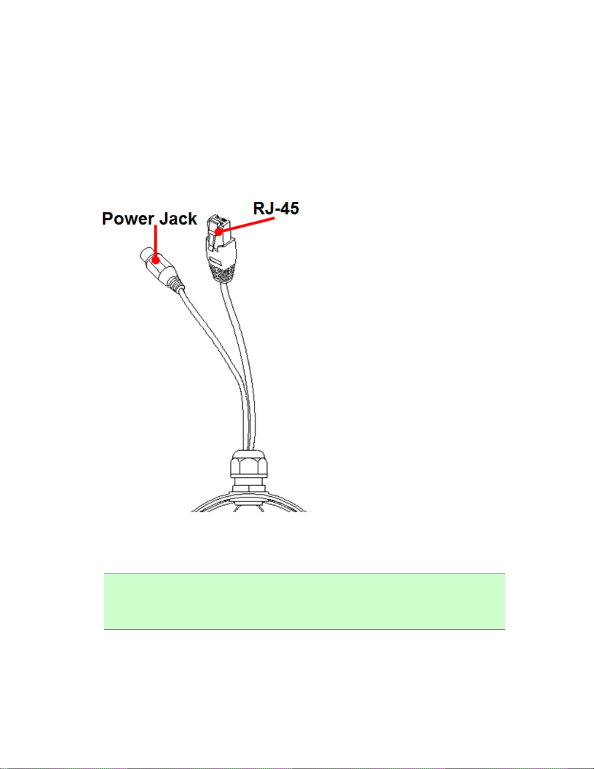
2.2.1 Identification of ICA-HM136 cable
1.RJ-45 LAN socket: Connect to PC or Hub/Switch.
For connect to 10Base-T Ethernet or 100Base-TX Fast Ethernet cabling. This Ethernet port built
N-Way protocol can detect or negotiate the transmission speed of the network automatically.
Please use CAT-5 cable to connect the Network Camera to a 100Mbps Fast Ethernet network
switch or hub.
2.Power Jack: The input power is DC 12V.
NOTE: ONLY u se package po wer a dapter supplie d with the Intern et. Otherwi se, the
product may be damaged.
9
Page 10
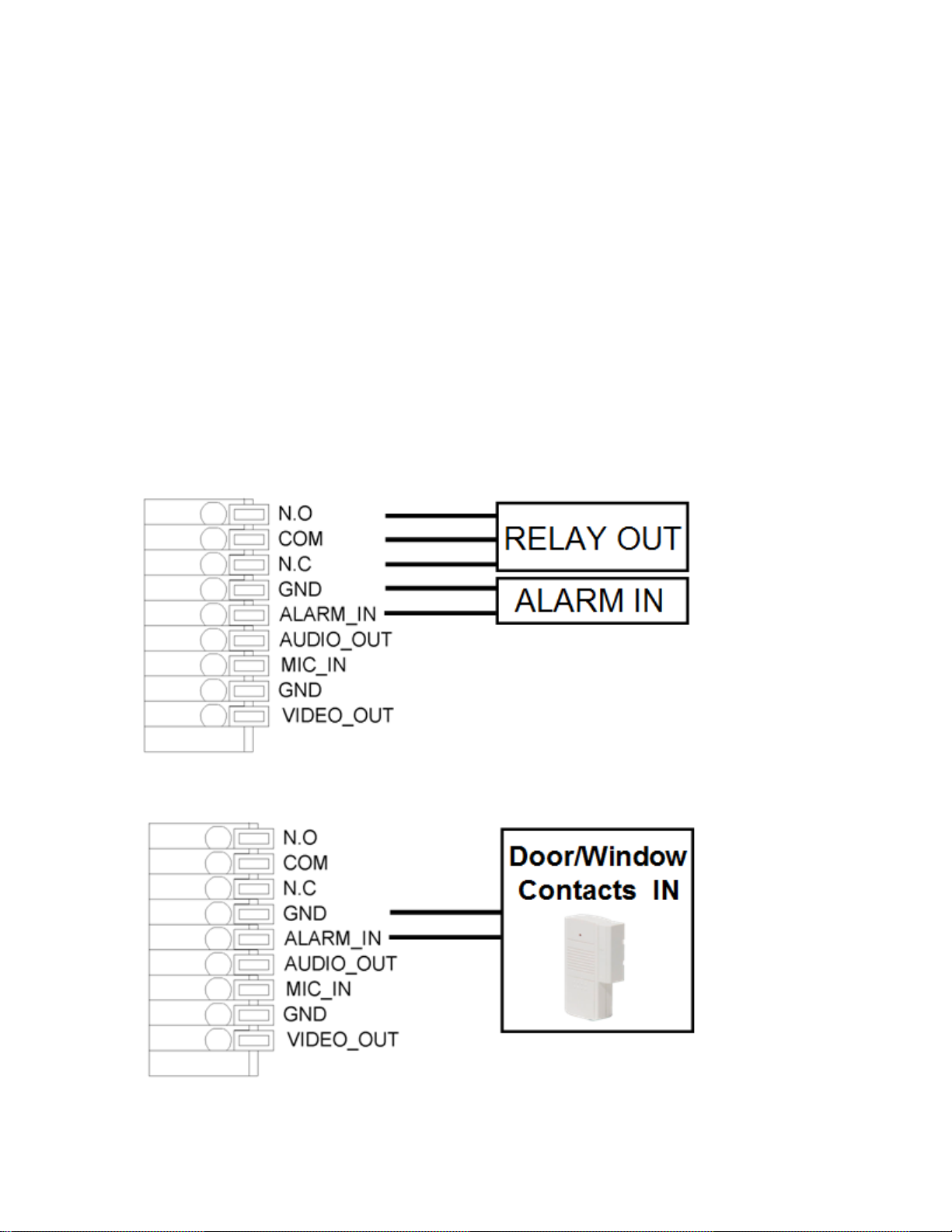
2.2.2 ICA-HM136 I/O Control Instruction
I/O terminal connector – used in application, for e.g., motion detection, event triggering,
(1)Digital Input: (GND+Alarm)
An alarm input for connecting devices that can toggle between an open and closed circuit, for
example: PIRs, door/window contacts, glass break detectors, etc. When a signal is received the
state changes and the input becomes active.
(2)Relay output: (COM +N.O.) / (COM+N.C.)
An output to Relay switch, for example: LEDs, Sirens, etc.
1.Digital Input:
Alarm Input:
1. GND (Ground) : Initial state is LOW
2. Alarm : Max. 50mA, DC 3.3V
2.Relay Output:
1. N.C. (Normally Close): Max. 1A, 24VDC or 0.2A, 110~240VAC
2. COM: (Common)
3. N.O. (Normally Open): Max. 1A, 24VDC or 0.2A, 110~240VAC
3
.Relay Connection:
(1)Digital Input connection
10
Page 11
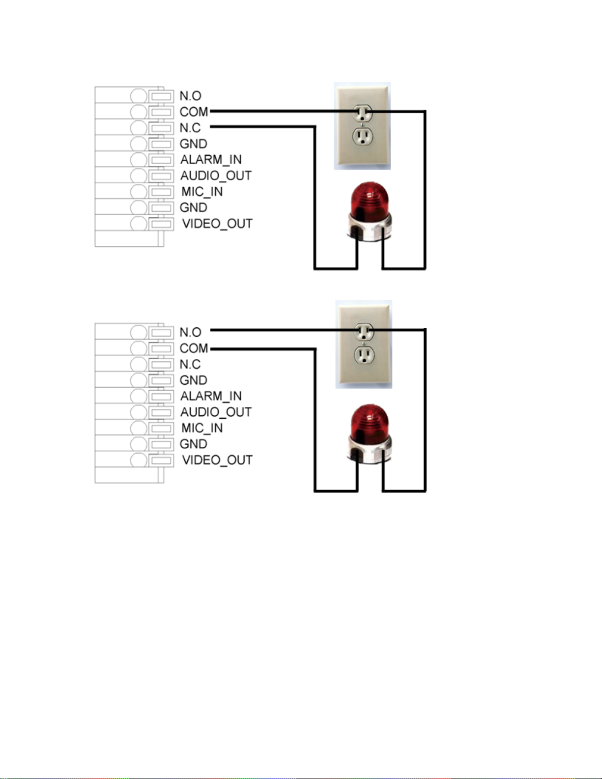
(2)Relay Output Connection
Or
4.MIC_IN:
Connect a microphone to the network camera.
5.AUDIO_IN
Connect a loud speaker to the network camera. This is for voice alerting and two-way audio.
11
Page 12
2.3 Hardware Installation
2.3.1 Physical Installation
1. Fix Internet camera to desired location with mount fixture
2. Connect an Ethernet cable
Connect the LAN cable on the camera to the network device (hub or switch).
NOTE: If there has an IEEE802.3af PoE swit ch in you r n etwork, you can connect the
camera LAN cabl e to thi s PoE switch to obt ain power. The power ada pter is
unnecessary when Internet camera is connected to a PoE switch.
12
Page 13
3. Attach the power supply
Plug in power adapter and connect to power source. After power on, the camera will st art to
operate.
NOTE: 1. Only use the power ada pter suppli ed with Internet came ra Othe rwise, the
product may be damaged.
2. The power a dapter is unn ecessary wh en Internet camera is con nected to a
PoE switch. Otherwise, the product may be damaged when Internet camera is
connected to a PoE switch and power adapter simultaneously.
4. Attach BNC connector
Connect the video BNC conne ctor to a monitor set if necessary check came ra viewing angle
and focus.
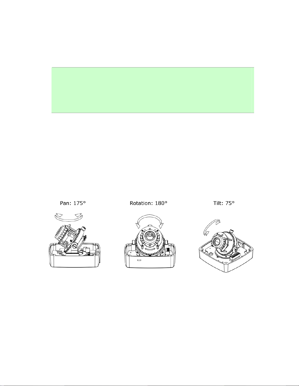
5. 3-Axis Gimbal Adjustments
Once the users open the case, the gimbal adjustment offers the convenience method to install
on the wall. The pan, tilt, and rotation are provided in this model. The users can adjust the
gimbal with Pan 175 degree, tilt 75 degree, and rotation 180 degree respectively.
13
Page 14
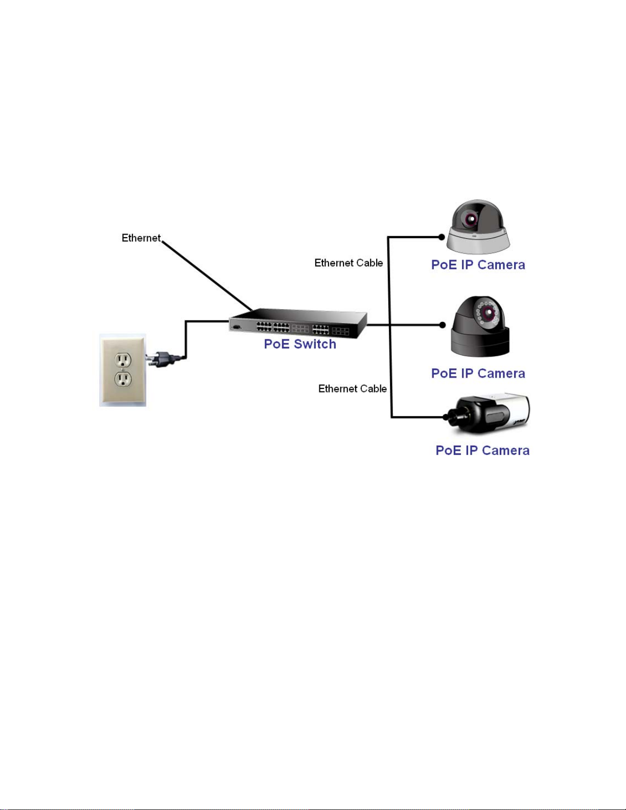
6. PoE (Power Over Ethernet)
Power over Ethernet (P oE) is a te chnology t hat i ntegrates p ower i nto a standard LA N
infrastructure. It enables power to be provided to the network device, such as an IP phone or
a network ca mera, using the same cabl e as that use d for network conne ction. It eliminates
the need fo r powe r outle ts at the ca mera lo cations an d en ables ea sier a pplication of
uninterruptible power supplies (UPS) to ensure 24 hours a day, 7 days a week operation.
14
Page 15
2.4 Initial Utility Installation
This chapter sho ws how to quick set up your H.264 cam era. T he ca mera is with the def ault
settings. However to hel p you find the networked came ra quickly the windows utility PLANET IP
Installer can search the cameras in the network that shall help you to configure some basic setting
before you started advanced management and monitoring.
1. Insert the bundle d CD into the CD-ROM drive to launch the auto-run p rogram. Once
completed, a welcome menu screen will appear.
2. Click the “PLANET IPInstaller” hyperlink; you will see the dialog box as below.
NOTE: If the welco me scre en d oes n ot appe ar, click “Start” at the t askbar. Th en, se lect
“Run” and type “D:\Utility\PLANETIPinstaller\PLANETIPinstaller.exe”, assume D
drive is your CD-ROM drive.
2.5 Initial Utility Installation
When you installed the camera on a LAN environment, you may execute PLANET IP Installer to
discover camera’s IP address and set up related parameters in the camera.
2.5.1 Search and Configure Network by PLANET IP Installer
When you i nstalled the Camera on a L AN environment, you have two e asy ways to search your
Cameras by PLANET IP Installe r or UPnP discov ery. Here is th e way to execute PLANE T IP
Installer to discover Camera’s IP address and set up related parameter in a Camera.
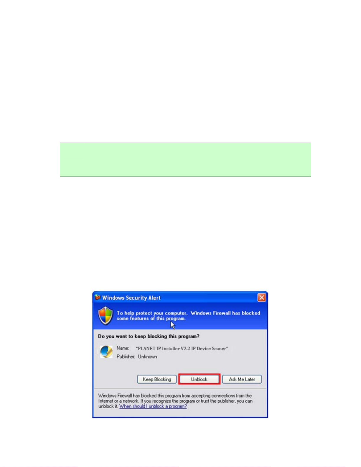
Search and Configure Network
1. OS: Windows XP SP2 or above. If the following “Windows Security Alert” popup, please click
“Unblock”.
15
Page 16

2. The GUI of IP Installer is as follows (Default IP: 192.168.0.20).
(1) IP Installer will search all IP Cameras connected on LAN. The user can click “Search
Device” to search again.
(2) Click one of IP Cameras listed on the left side of IP Installer, then the network configuration
of that IP Camera will be listed on the right side. If parameters changed, click on “Submit”.
Then, the network configuration will be changed. Just click “OK” to reboot
16
Page 17
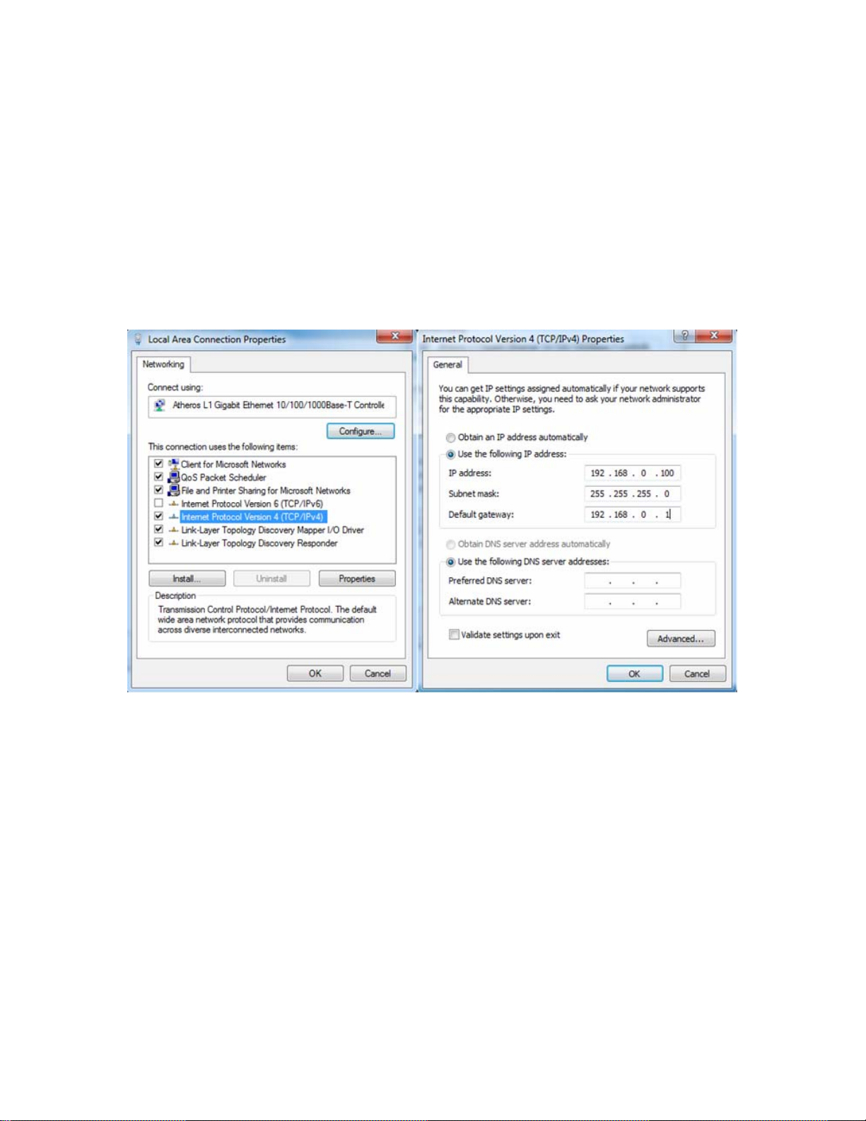
(3) Please make sure the subnet of PC IP address and IP CAM IP address are the same.
IP CAM IP address: 192.168.0.20
PC IP address: 192.168.0.100
(4) Different Subnets:
IP CAM IP address: 192.168.0.20
PC IP address: 192.168.1.100
(5) To Change PC IP address:
Control PanelÆNetwork ConnectionsÆLocal Area Connection PropertiesÆInternet Protocol
(TCP/IP) ÆProperties
Please make sure your IP Camera and PC have the same Subnet. If not, please change IP
Camera IP subnet or PC IP subnet accordingly.
(6) A quick way to access remote monitoring is to left-click the mouse twice on a selected IP
Camera listed on “Device list” of PLANET IP Installer. An IE browser will be opened.
(7) Then, please key in the default “Username: admin” and “Password: admin” in the
following message box.
17
Page 18
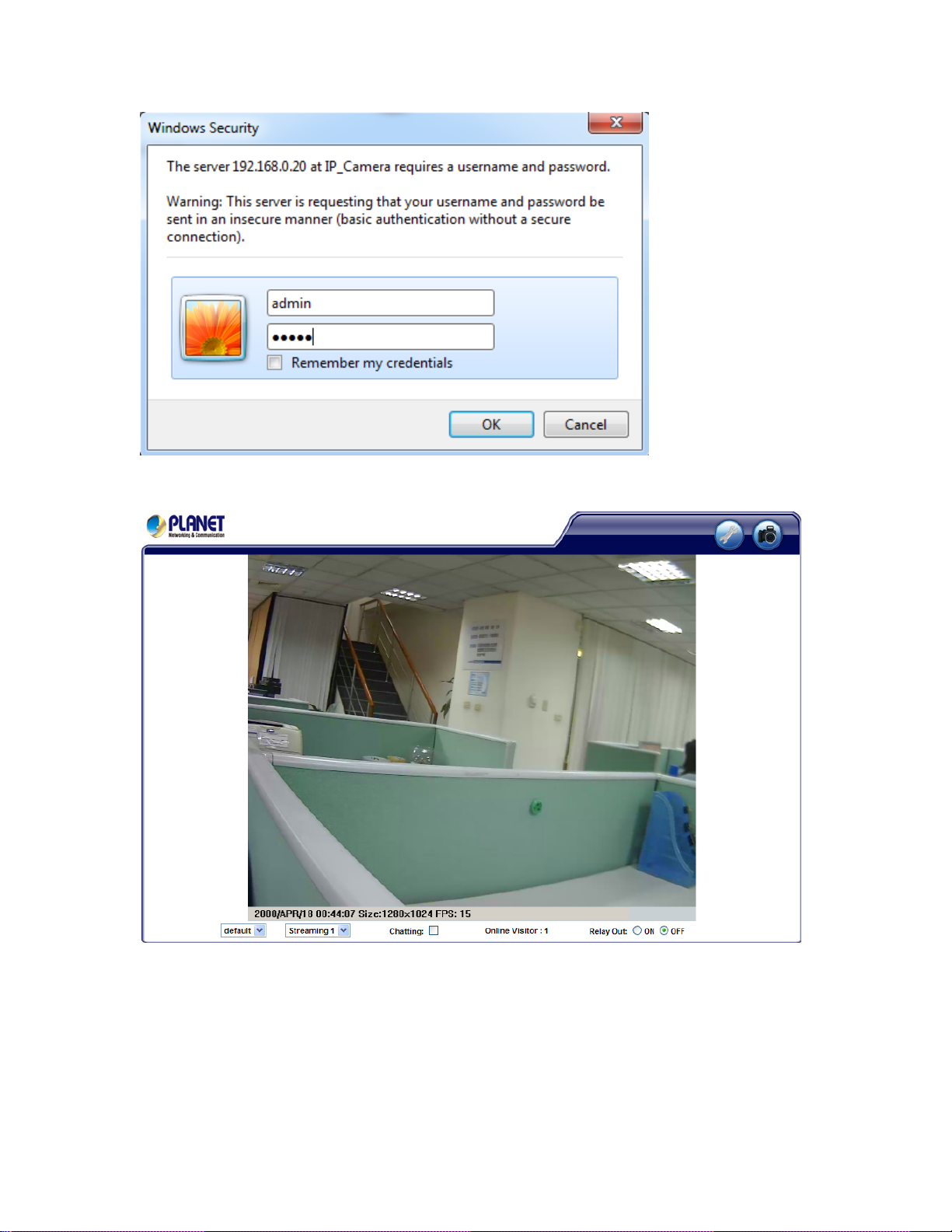
(8) If the user name and password are input correctly, the following web page will be displayed.
18
Page 19
2.6 Setup ActiveX to use the Internet Camera
The Internet camera web pages communicate with the Internet camera using an ActiveX control.
The ActiveX control must be downloaded from the Internet camera and installed on your PC. Your
Internet Explore r se curity settings mu st allow for the web pag e to work correctly. To use th e
Internet camera, user must setup his IE browser as follows:
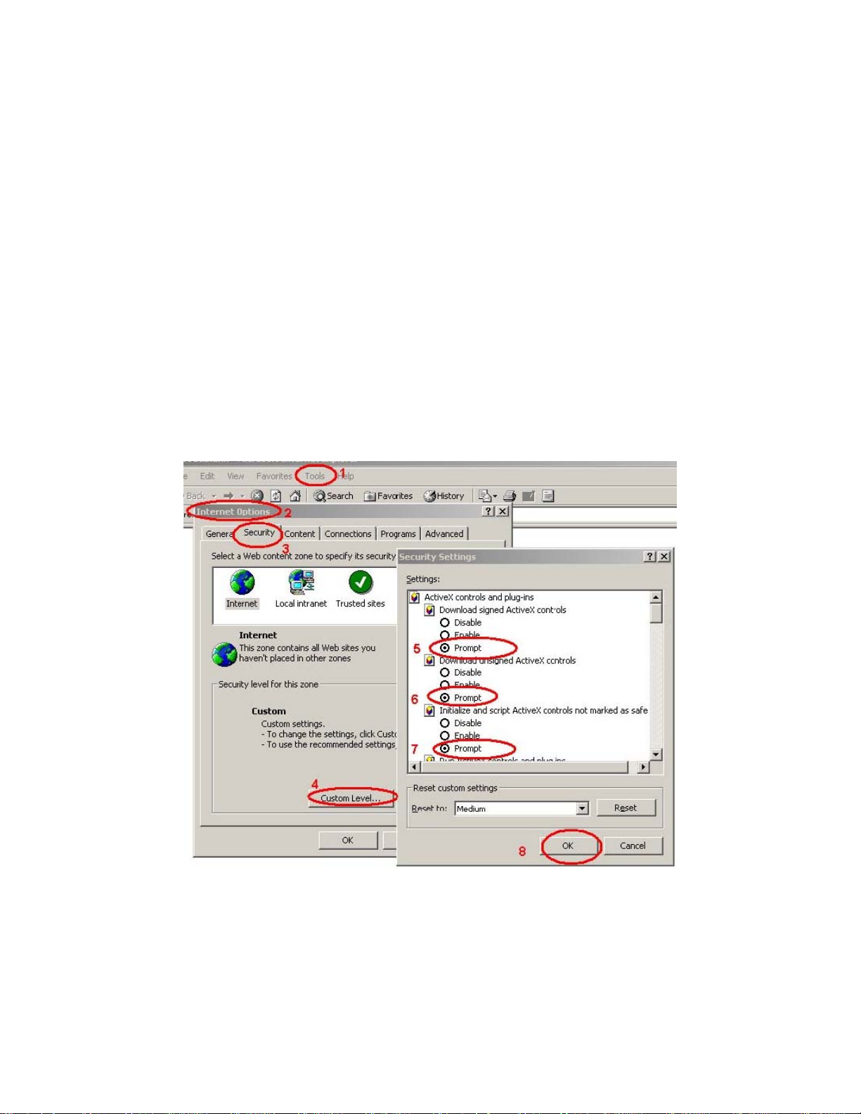
2.6.1 Internet Explorer 6 for Windows XP
From your IE browse Î ”Tools” Î ”Internet Options…” Î ”Security” ΔCustom Level…”, please
setup your “Settings” as follow.
Set the first 3 items
• Download the signed ActiveX controls
• Download the unsigned ActiveX controls
• Initialize and script the ActiveX controls not masked as safe to Prompt
By now, you have finished your entire PC configuration for Internet camera.
19
Page 20
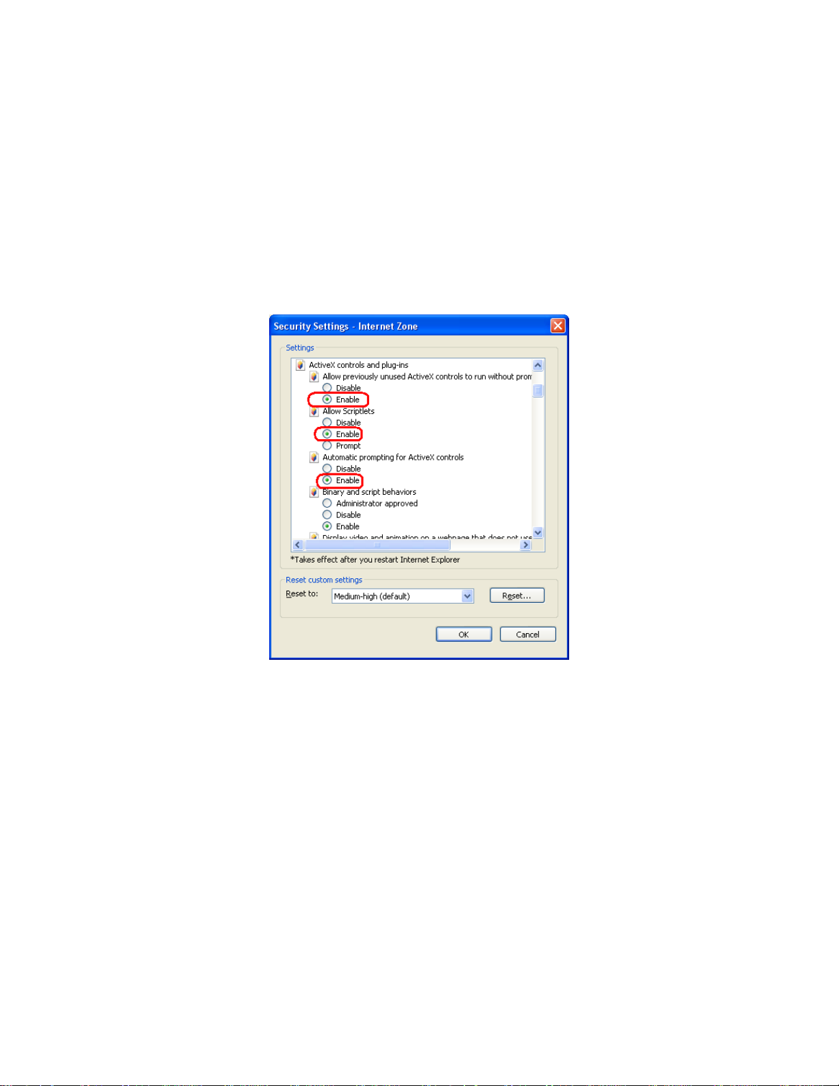
2.6.2 Internet Explorer 7 for Windows XP
From your IE browse Î ”Tools” Î ”Internet Options…” Î ”Security” ΔCustom Level…”, please
setup your “Settings” as follow.
Set the first 3 items
• Allow previously unused ActiveX control to run…
• Allows Script lets
• Automatic prompting for ActiveX controls
By now, you have finished your entire PC configuration for Internet camera.
20
Page 21
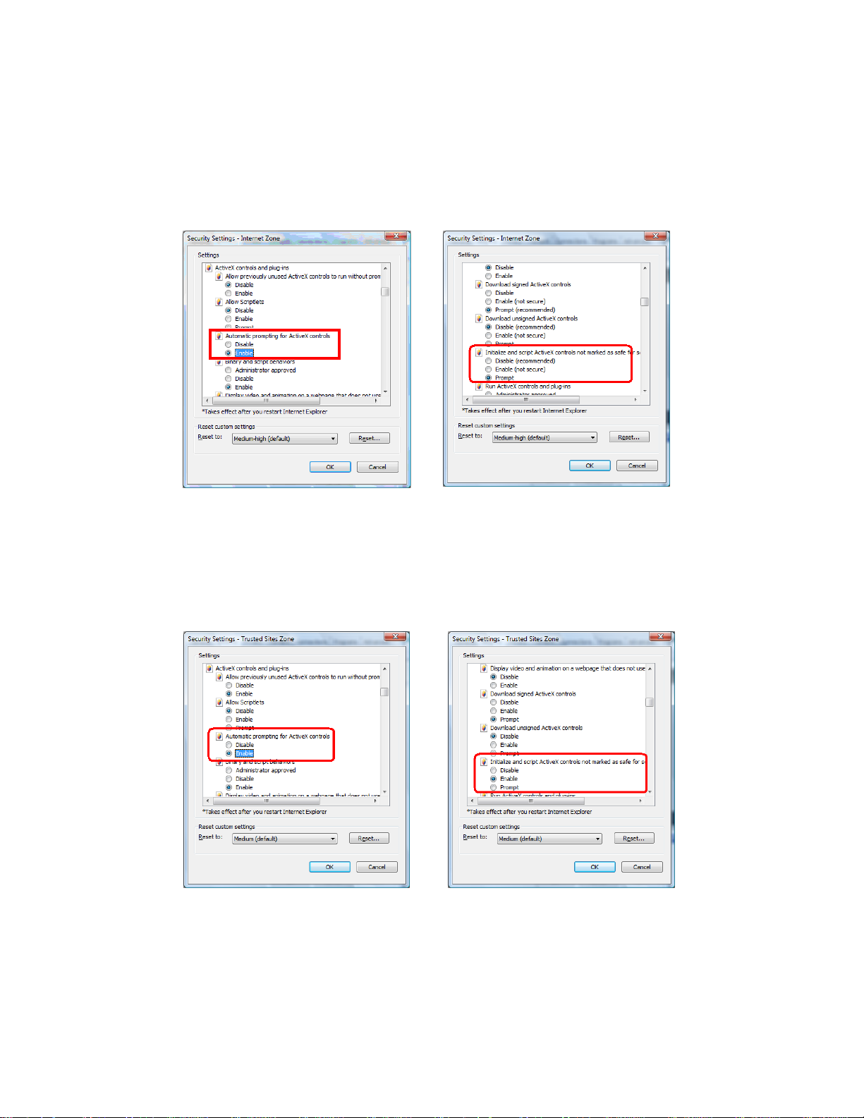
2.6.3 Internet Explorer 7 for Windows Vista
From yo ur IE bro wse Î ”Tools” Î ”In ternet Options…” Î ”Se curity” Î ”Int ernet” ΔCustom
Level…”, please setup your “Settings” as follow.
• Enable “Automatic prompting for ActiveX controls”
• Prompt “Initialize and script active controls not marked….”
From your I E browse Î ”Tool s” Î ”Internet Option s…” Î ”Secu rity” Î ”Truste d Sites”
ΔCustom Level…”, please setup your “Settings” as follow.
• Enable “Automatic prompting for ActiveX controls”
• Prompt “Initialize and script active controls not marked….”
By now, you have finished your entire PC configuration for Internet camera.
21
Page 22

3. Web-based Management
This chapter provides setup details of the Internet camera’s Web-based Interface.
3.1 Introduction
The Internet came ra ca n be configu red with your Web Browser. Before configure, plea se make
sure your PC is under the same IP segment with Internet camera.
3.2 Connecting to Internet Camera
z Use the following procedure to establish a connection from your PC to the camera.
z Once connected, you can add the camera to your Browser’s Favorites or Bookmarks.
Start the web browser on the comput er and type the IP address of the ca mera. The Default I P:
“ http://192.168.0.20
“
The login window of Internet camera will appear, Default login username/password is:
admin/ admin
;
NOTE: If the Use r name and Password have been chang ed with PLANET IP Installer,
please enter the new User name and Password here.
22
Page 23

Web b rowser may display the “ Security Warming” window, sele ct “ Yes” to inst all and run the
ActiveX control into your PC.
After the ActiveX control was installed and run, the first image will be displayed.
NOTE: If you log in the camera as an ordinary user, setting function will be not available. If
you log in the cam era a s the admini strator, you can p erform all the settings
provided within the device.
23
Page 24

4. Live View
Start-up screen will be as follow no matter an ordinary users or an administrator.
(1)Configure
(2)Snapshot
(3)Status Bar
(4)Screen Size
(5)Streaming Select
(6)Chatting Function
Get into the administration page.
.Video Snapshot
Show system time, video resolution, and video refreshing rate.
Select video scree n “ default, 1/2x, 1x, 2x” for view currently
camera screen size.
Select video strea ming source (When strea ming 2 setting in
『Video Setting』 is closed, this function will not display)
IP Camera suppo rts 2 -way audio. Click the “ Chatting” ch eck
box. Then you can use microphone which connects to the PC to
talk to server side, which is IP Camera side
24
Page 25

.
(7)Online Visitor
Shows how many people connect to this IP camera.
(8)Relay Control
Double-click the video; it will chan ge to full screen m ode. Press “ Esc” or double-click the video
again, it will change back to norm al m ode. Ri ght-Click the mouse on the vi deo, it will show a
pop-up menu.
Control the relay which is connected to this camera.
(1)Snapshot
(2)Record Start
Save a JPEG picture.
Record the vi deo in th e local PC. It will ask you where to save
the video. To stop recording, right-click the mouse again. Select
“Record Stop”. The vide o format is A VI. Use Microsof t Me dia
Player to play the recorded file.
(3)Mute
(4)Full Screen
(5)ZOOM
Turn of the audio. Click again to turn on it.
Full-screen mode.
Enable zoom-in and zoom-out functions. Select “ Enable digital
zoom” option first within the pop-up dialogue box and then drag
and drop the bar to adjust the zoom factors.
25
Page 26

5. Configuration
Click to get into the administration page. Click to go back to the live
video page.
26
Page 27

5.1 System
5.1.1 System Information
1. Server Information: Set up the camera name, select language, and set up the camera time.
Server Name
This is the Camera name. This name will show on the IP
Installer.
There are English, Traditional Chinese, Simplified
Chinese, French, Russian, Italian, Spanish, German,
Select language
Portuguese and Polish to select. When change, it will show
the following dialogue box for the confirmation of
changing language.
2. OSD Setting: Select a position where date & time stamp / text showing on screen.
Moreover, click Text Edit can entry to adjust the OSD contents which is including Size and Alpha of text.
Finally, click button to reserve the setting.
27
Page 28

3.
Server time s etting:Select option s to set up time - “ NTP”, “ Synchronize with PC’s time”,
“Manual”, “The date and time remain the same”.
28
Page 29

5.1.2 User Management
IP CAMERA supports three different users, administrator, general user, and anonymous user.
Anonymous User Login
Add user
Yes:Allow anonymous login
No:Need user name & password to access this IP camera
Type the user name and password, then click “Add/Set”.
Click “edit” or “delete” to modify the user
29
Page 30

5.1.3 System Update
Firmware Upgrade
Reboot System
Factory default
Setting Management
To update th e firmwa re o nline, cli ck “ Browse…” t o sele ct t he
firmware. Then click “Upgrade” to proceed.
Re-start the IP camera.
Delete all the settings in this IP camera.
User may do wnload the current setting to PC, or upgrad e from
previous saved setting.
Setting download:
Right-click the mouse button on Setting Download Æ Select “Save AS…” to save current IP CAM
setting in PC Æ Select saving directory Æ Save
Upgrade from previous setting:
Browse Æ search previous setting Æ open Æ upgrade Æ Setting update confirm Æ click
index.html
. to return to main page
30
Page 31

5.2 Network
5.2.1 IP Setting
IP Camera supports DHCP and static IP.
DHCP
Static IP
Port Assignment
Using DHCP , IP Camera will get all the network parameters
automatically.
Please type in IP addre ss, sub net m ask, gateway , and DNS
manually.
User may need to assign dif ferent port to avoid conflict whe n
setting up IP assignment.
(1) Web Page Port: setup web page connecting port and video
transmitting port (Default: 80)
(2) RTSP Port: setup port for RTSP transmitting (Default: 554)
(3) RTP Start and End Po rt: in RTSP mode, you may use TCP
and UDP for con necting. TCP connection uses RTSP Port
(554). UDP connection uses RTP Start and End Port.
31
Page 32

This IP camera supports UPnP, If this service is enabled on your
UPnP
computer, the camera will autom atically be detected and a new
icon will be added to “My Network Places.”
Note: UPnP must be enabled on your computer.
Please follow the procedure to activate UPnP
5.2.2 Using UPnP of Windows XP or Vista
5.2.2.1 Windows XP
UPnP™ is short for Universal Plug a nd Play, whi ch is a n etworking a rchitecture that p rovides
compatibility among network ing equipment, software, and perip herals. Thi s device i s an UPnP
enabled device. If the operating system, Windows XP, of your PC is UPnP enabled, the device will
be very easy to configure. Use the following steps to enable UPnP settings only if your operating
system of PC is running Windows XP.
NOTE: Windows 2000 does not support UPnP feature.
Go to Start > Settings, and Click Control Panel
32
Page 33

The “Control Panel” will display on the sc reen and double click “Add or Remove Programs” to
continue
The “Add or Remove Programs” will display on the screen and click Add/Remove Widows
Components to continue.
33
Page 34

The following screen will appear, select “Networking Services” and click “Details” to continue
The “Networking Services” will display on the screen, select “Universal Plug and Play” and click
“OK” to continue.
34
Page 35

Please click “Next” to continue
The program will start inst alling the UP nP automatically. You w ill see the below pop-up screen,
please wait while Setup configures the components.
35
Page 36

Please click “Finish” to complete the UPnP installation
Double-click “My Network Places” on the desktop, th e “My Network Places” will display on the
screen an d d ouble-click th e UPnP icon with Inter net came ra to view you r device in a n Internet
browser.
36
Page 37

5.2.2.2 Windows Vista
UPnP™ is short for Universal Plug a nd Play, whi ch is a n etworking a rchitecture that p rovides
compatibility among network ing equipment, software, and perip herals. Thi s device i s an UPnP
enabled device. If the operating system, Windows Vista, of your PC is UPnP enabled, the device
will be very easy to configure. Use the followi ng steps to enable UPnP settings only if your
operating system of PC is running Windows Vista.
Go to Start > Control Panel > Network and Internet > Network and Sharing Center, and turn
on “Network Discovery”.
37
Page 38

Double-click “My Network Places“ on the desktop, the “ My Netw ork Places” will display on the
screen an d d ouble-click th e UPnP icon with Internet came ra to view you r device in a n Internet
browser.
38
Page 39

5.2.3 PPPoE
PPPoE: Stands for Point to Point Protocol over Ethernet
A st andard b uilds on Eth ernet an d Point-to-Poi nt network p rotocol. It allows Internet ca mera
connect to Internet with xDSL or cable connection; it can dial up your ISP and get a dynamic IP
address. For more PPPoE and Internet configuration, please consult your ISP.
It can directly connect to the xDSL, however, it should be setup on a LAN environment to program
the PPPoE information first, and then connect to the xDSL modem. Power on again, then the
device will dial on to the ISP connect to the WAN through the xDSL modem.
The procedures are:
(1) Select “Enabled” to use PPPoE.
(2) Key-in Username and password for the ADSL connection.
(3) Send mail after dialed:When connect to the Internet, it will send a mail to a specific mail
.account. For the mail setting, please refer to “Mail and FTP” settings.
5.2.4 DDNS
DDNS: Stands for Dynamic Domain Name Server
The device supports DDNS If your device is co nnected to xDSL directly, you might need this
feature. However, if y our device is behind a NAT router, y ou will not need to enable this feature.
Because DDNS allows the device to use an easier way to remember naming format rather than an
IP address. The name of the domain i s like the name of a person, and the IP addre ss is like his
phone number. On the Internet we have IP numbers for each ho st (computer, server, router, and
so on), and we replace these IP numbers to easy remember names, which are organized into the
domain name. As to xDSL environment, most of the users will use dynamic IP addresses. If users
want to set up a web or a FTP serve r, then the Dynamic Domain Name Server is necessary. For
more DDNS configuration, please consult your dealer.
Your Intern et Service Pro vider (ISP) p rovides you at least one IP addre ss which you u se to
connect to the Internet. The address you get may be static, meaning it never changes, or dynamic,
meaning it’s likely to chan ge perio dically. Ju st how often it changes, dep ends on your ISP. A
dynamic IP address complicates remote access since you may not know what your current WA N
39
Page 40

IP address is when you want to access your network over the Internet. The solution to the dynamic
IP address problem comes in the form of a dynamic DNS service.
The Internet use s DNS se rvers to lookup domain names and tra nslates them into IP addre sses.
Domain names are ju st easy to remember alia ses for IP addresses. A dynamic DNS se rvice is
unique because it provides a means of updating your IP address so that your l isting will remain
current when your IP address ch anges. There are several excellent DDNS services availa ble on
the Internet and best of all they’re free to use. One such service you can use is www.DynDNS.org.
You’ll need to register with the service and set up the domain name of your choice to begin using it.
Please refer to the hom e p age of the service for detailed instructions or refer to Appendix E for
more information.
DynDns.org, the procedures are:
(1) Enable this service
(2) Key-in the DynDNS server name, user name, and password.
(3) Set up the IP Schedule update refreshing rate.
(4) Click “Apply”
(5) If setting up IP schedule update too frequently, the IP may be blocked. In general, schedule
update every day (1440 minutes) is recommended.
40
Page 41

Camddns, the procedures are:
(1) Please enable this service
(2) Key-in user name.
(3) IP Schedule update is default at 5 minutes
(4) Click “Apply”.
DDNS Status
(1) Updating:Information update
(2) Idle:Stop service
(3) DDNS registration successful, can now log by http://<username>.ddns.camddns.com:
Register successfully.
(4) Update Failed, the name is already registered:The user name has already been used.
Please change it.
(5) Update Failed, please check your Internet connection:Network connection failed.
(6) Update Failed, please check the account information you provide:The server, user name,
and password may be wrong.
41
Page 42

5.2.5 Mail & FTP
To send out the video via mail of ftp, please set up the configuration first.
42
Page 43

5.3 A/V Setting
5.3.1 Image Setting
For the security purpose, there are three areas can be setup for privacy mask. Click “Area” button
first and pull an area on the above image. Finally, click “Save” button to reserve the setting. Adjust
“Brightness”, “ Contrast”, “ Hue”, “ Saturation” to get clear vide o. Moreover, the ICA-HM136I
supports “Back Light Compensation(BLC)”, “Night Mode” and “Video Orientation”.
5.3.2 Video Setting
User may select 2 streaming output simultaneously:
Streaming 1 Setting
Streaming 2 Setting
Basic mode and Advanced mode.
Basic mode, Advanced mode, and 3GPP mode
43
Page 44

NOTE: Max Video Frame Rate for both streaming combined is 30 FPS.
Video System: click the drop down list to select the system type “NTSC/PAL”.
Streaming 1 and 2Basic Mode:
There are 8 resolutions can be chosen.
Resolution
Quality
1600x 12 00, 1280x10 24, 1280x 960, 1280x72 0, 800x600,
640x480, 320x240, 176x144
There are 5 levels to adjust:
Best/ High/ Standard/ Medium/ Low
The higher the quality is, the bigger the file size is.
Also not good for Internet transmitting
Video Frame Rate
Video Format
RTSP Path
The video refreshing rate per second.
H.264 or JPEG.
RTSP output name.
44
Page 45

Streaming 1 and 2 Advanced Mode:
There are 8 resolutions can be chosen.
Resolution
Bitrate Control Mode
1600x 12 00, 1280x10 24, 1280x 960, 1280x72 0, 800x600,
640x480, 320x240, 176x144
There are CBR﹝Constant Bit Rate﹞ and VBR﹝Variable Bit
Rate﹞to use.
CBR:32Kbps~4Mbps (the higher the CBR is, the better the
video quality is)
VBR:1(Low) ~10(High) – Compression rate, the higher the
compression rate, the lower the picture quality is; vise versa.
The balance between VBR and network bandwidth will affect
picture quality. Please carefully select the VBR rate to avoid
picture breaking up or lagging.
Video Frame Rate
GOP Size
Video Format
RTSP Path
The video refreshing rate per second.
It means "Group of Pictures". The higher the GOP is, the better
the quality is.
H.264 or JPEG.
RTSP output name.
45
Page 46

3GPP Streaming mode:
Enable or Disable
3GPP Path
Enable or Disable 3GPP Streaming.
3GPP output name.
NOTE: 3GPP mode suggested setting: 176x144 resolutions, 5FPS, MPEG4 format.
5.3.3 Audio
The ICA-HM 136 supp orts 2-way audio . Use r can send au dio from ICA-HM1 36 Built-in m ic to
remote PC; User can also send audio from remote PC to ICA-HM136’s external speaker.
(1) Audio from IP camera built-in mic to local PC: select “Enable” to start this function.
(2) Audio from local PC to ICA-HM136: Check “chatting” in the browsing page.
46
Page 47

NOTE: The Audio will not be smooth when enable SD card recording function simultaneously.
47
Page 48

5.4 Event List
The ICA-HM136 provides multiple event settings.
5.4.1 Event Setting
48
Page 49

Motion Detection
Record File Setting
Record Time Setting
Network Disconnected
Network IP check
5.4.2 Schedule
IP CAMERA allows 3 are as motion de tection. Whe n motion is
triggered, it can send the video to some specific mail addresses,
transmit the video to remote f tp serve r, trigger the relay , and
save video to local SD card. T o set up the motion area, click
“Area Setting ”. Usi ng mo use to d rag a nd draw the area. T he
same operation for area 2 and 3.
IP CAMERA allows 3 dif ferent types of recording file to chang e
its re cord size. Whe n mo tion/alarm i s trigge red, th ere a re 3
different types of record mode.
(1) AVI File (With Record File Setting )
(2).Multi-JPEG (With Re cord File Setting), only with JPEG
compression format.
(3) Single JPEG (Single File with Interval Setting)
Pre Alarm an d Post Alarm setups for video st art and end time
when motion detected, I/O, or other devices got triggered.
Note: Pre/Post Alarm reco rd time is base on record time setting
and IP Cam built-in Ram memory. Limited by IP Cam built-in
Ram Memory, When information is too much or video quality set
too high, it wi ll cause recording frame drop or d ecrease on post
alarm recording time.
When the network is down, it will sav e the video t o local SD
card.
Note: This function is only enabled in wire connection.
When the connection is d own, it reco rds the video to SD card.
Make sure the video re cording i s continuo us. T o use thi s
function, key in the IP address of the PC which ha s recording
software inst alled. Enabl e the f unction of “Save to SD ca rd”,
then click “Apply”.
Note: The i nterval of two v ideo files on SD card is fixed with 30
seconds.
Schedule
Snapshot
After complete the schedule se tup, the camera dat a will be
recorded according to the schedule setup.
After enable the sn apshot function, user can sele ct the stora ge
position of snap shot file, the interval time of sna pshot and the
reserved file name of snapshot.
49
Page 50

5.4.3 I/O Setting
The ICA-HM136 supports 1 input/ 1 output. When input is triggered, it can send the video to some
specific mail addresses, transmit the video to remote ftp server, trigger the relay, and save video to
local SD card.
NOTE: Please connect to propriety relay box to reduce the risk of electric shock & damaged.
50
Page 51

Alarm Input Setting
GPIO Output Setting
By GPIO I/O port input that prov ides related action while I/O
input triggered.
By GPIO I/O port outp ut that provides O nOff Switch, Slide
Switch & Pan/Tilt Module for using with relay box.
GPIO pin define please refer to the part of Front / Back plane & I/O port pin assignment.
GPIO 0
GPIO 1
GPIO 2
GPIO 3
ALARM INPUT
Normal: 3.3V (The voltage differential from GPIO pin & GND)
Active: 0V (GPIO 0 & GPIO1 link to PIN2 GND)
ALARM OUTPUT
Normal: 3.3V (The voltage differential from GPIO pin & GND)
Active: 0V (GPIO 0 & GPIO1 link to PIN2 GND)
GPIO INSTALLATION EXAMPLE 1
Trigger a normal off (Normal Open) alarm siren on when event/motion occur at COM:
51
Page 52

GPIO INSTALLATION EXAMPLE 2
Trigger the normal on (Normal Close) indoor illumination off when event / motion occur at COM:
5.4.4 Log List
Sort by System Logs, Motion Detection Logs and I/O Logs. In addition, System Logs and I/O Logs
won’t lose data due to power failure.
5.4.5 SD Card
Please Insert SD cards before use it. Make sure pushing SD card into the slot completely.
52
Page 53

NOTE:
The use of the SD card will affect the operat ion of the IP CAMERA slightly, such as
affecting the frame rate of the video.
Playback, the procedures are:
(1) It will show the capacity of the SD card. Click the date listed on this page. It will show the list
of the video.
(2) The video format is AVI. Click the video to start Microsoft Media Player to play it.
(3) To delete the video, check it, and then click Del. When the SD card is full, it will remove the
oldest video automatically.
53
Page 54

Appendix A: Factory Default
To recover the default IP address and password, please follow the following steps.
(1) Remove power and Ethernet cable, and press and hold the button in the back of IP CAMERA.
(2) Power on (don’t plug Ethernet cable) the camera. Don’t release the button during the system
. booting.
(3) It will take around 30 seconds to boot the camera.
(4) Release the button when camera finishes proceed.
(5) Plug the Ethernet cable.
(6).Re-login the came ra usin g the default IP ( http://192.168.0.20
password (admin).
), and userna me (ad min),
54
Page 55

Appendix B: PING IP Address
The PING (st ands for Packet Internet Grop er) command is used to detect whether a spe cific IP
address is accessible by sending a packet to the specific address and waiting for a reply. It’s also
a very u seful tool to confirm Internet camera installed or if the IP address conflicts with any other
devices over the network.
If you want to make sure the IP address of Internet camera, utilize the PING command as follows:
z
Start a DOS window.
z
Type ping x.x.x.x, where x.x.x.x is the IP address of the Internet camera.
The replies, as illustrated below, will provide an explanation to the problem.
If you want to detect any other devices conflicts with the IP address of Intern et camera, also can
utilize the PING command but you must disconnect the Internet camera from the network first.
55
Page 56

Appendix C: 3GPP Access
To u se the 3GPP function, in addition t o previous section, you might nee d more information or
configuration to make this function work.
Note:
RTSP Port:
Port 554 is the default for RTSP service. Howeve r, sometim es, some se rvice providers cha nge
this port number for some reasons. If so, user needs to change this port accordingly.
Dialing procedure:
1. Choose a verified player (PacketVideo or Realplayer currently)
2. Use the following default URL to access:
Where host is the host name or IP address of the camera.
Compatible 3G mobile phone:
Please contact your dealer to get the approved list of compatible 3G phone.
That to use the 3GPP function, it strongly recommends to install the Networked Device
with a public and fixed IP address without any firewall protection.
rtsp://IP-Address/3g
Note:
Besides IP camera and 3G mobile phone. You will also need to make sure the
ISP and company has provided the 3GPP service to you.
56
Page 57

Appendix D: Bandwidth and Video Size Estimation
The frame ra te of video tr ansmitted from the Interne t camera d epends on con nection bandwidth
between client and serve r, video re solution, co dec type, and qu ality setting o f server. Here is a
guideline to help you roughly estimate the bandwidth requirements for your Internet camera.
The required bandwidth depends on content of video source. The slow motion vi deo will produce
smaller bit rate generally and fast motion will produce higher bit rate vice versa. Actual results
generated by the Internet camera may be varying.
Image
Resolution
160 x 120
(QQVGA)
320 x 240
(QVGA)
640 x 480
(VGA)
1280x1024
(SXGA)
1600x1200
(UXGA)
Average range of data
sizes for M-JPEG mode
3 ~ 6k byte per frame
8 ~ 20k byte per frame
20 ~ 50K byte per frame
100 ~ 200k byte per
frame
600 ~ 1500k byte per
frame
Average bit rate for
MPEG-4 mode
64kbps~256kbps
@ 30fps
256kbps~768kbps
@ 30fps
512kbps~2048kbps @
30fps
NA
NA
Average bit rate for
H.264 mode
32kbps~192kbps
@ 30fps
192kbps~512kbps
@ 30fps
384kbps~1536kbps
@ 30fps
512kbps~3076kbps
@ 15fps
640kbps~6144kbps
@ 15fps
NOTE:
Audio stream ing also take s ban dwidth around 5 kbps to 64 kbps. Most xDSL/Cabl e
modem upload speeds may not even reach up to 128 kbps. Thus, you may not be able
to receive an y video while streamin g audio on a 128 kbp s or lower con nection. Even
though th e upload spee d is m ore than 1 28kbps, for optimal video pe rformance,
disabling audio streaming will get better video performance.
57
Page 58

Appendix E: DDNS Application
1. Preface
If you have a Cable modem or xDSL, this is a great way to host your own Networked Device or
other TCP/IP Service. Get your own domain like www.yourname.com, www.yourname.com.tw
etc. (Note: This domai n must be regi stered with Interni c via registratio n authoritie s su ch as
Network Solutions, DirectNIC, Register.com etc). Your domain name's dynamic IP address is
automatically tracked by a DDNS server.
Host your own Networked Device and much more no matter what your computer's IP address
may be and even if you h ave dialup, DSL or c able modem Internet conn ection where you r
computer's I P addre ss chang es all th e time!! DDNS service su pports all top level domai n
names including but not limited to .com, .net, .org, .to, .uk etc.
2. Ethernet Network Environment
Normally, DDNS se rvice is only ne cessary for the users that could only obt ain dynami c IP
addresses. As to the u sers that co uld obtain the static va lid IP address, they do not u sually
have to appl y the DDNS servi ce. Befo re we d ecide if DDNS is n ecessary for the use rs, we
have to check what kin d o f Ethernet network enviro nment we have to inst all our Net worked
Device on.
(1) Environment of Fixed Valid IP Network
If users co uld obt ain valid IP addresse s, they c ould save the ef fort to apply DDNS se rvice.
Because the IP address i n this environment i s fixed, use rs coul d input th e IP address or
domain name of demo site directly in the IE browser.
(2) Environment of Dynamic IP Net work
If users is un der an environment of dynamic IP network (Dial-up xDSL), they h ave to apply a
domain name in advance. Then apply DDNS service. Finally setup the necessary information
of DDNS and PPPoE of the Networked Device in order to let the outside administrator be able
to access through Internet.
3. Application Steps – DDNS & Domain Name
(1). Visit the following web site: http://www.dyndns.org/
(2). Click “Account”
58
Page 59

(3). After the columns show up at the left side, click “Create Account”.
(4). Fill the application agreement and necessary information.
a. Username
b. E-mail address and confirmation
c. Password and confirmation
d. Submit all the input information and finish creating an account
59
Page 60

Click these two options
(5). Check your e-mail mailbox. There will be an e-mail with a title “Y our DynDNS Account
Information“. Click the hyperlink address to confirm the DDNS service that you just applied.
Then DDNS you applied activated.
Click to confirm
60
Page 61

(6). Enter the web page http://www.dyndns.org/
you just applied to login administration interface of DDNS server.
(7). If the correct u sername and password are input, you can see the followin g picture at th e
top-right of the login page.
(8). Click the “Services”.
Input your account
again. Input your username and password that
61
Page 62

(9). Click the “ Dynamic DNS ”.
(10). Click the “Create Hosts”.
(11). We could create a domain name without any charge at this step. First, we input the host
name. (No.1) Then we pick a domain that is easy to remember. Finally (No.2), click the “Add
Host” to submit the domain name information. (No.3)
1
3
2
4. Setup the DDNS and PPPoE of Network Device
At last, use rs have to e nter the web p age of Networked Device and setup the necessary
information of DDNS and PPPoE after the application of DDNS service. Please check the user
manual to access the DDNS and PPPoE p ages. Af ter saving the modification, rest art the
device. The external users coul d browse the Netwo rked Device by the input of their doma in
name.
62
Page 63

Appendix F: Configure Port Forwarding Manually
The device can be use d with a router. If the dev ice wants to be acce ssed from the W AN, its IP
address needs to be setup as fixed IP address, also the port forwarding or Virtual Server function
of router n eeds to be setu p. This device sup ports UPnP traversal function. Therefore, user could
use thi s feat ure to configure p ort forwardin g of NA T route r first. However, if use r ne eds to
configure port forwarding manually, please follow the steps as below:
Manually installing the device with a router on your network is an easy 3–step procedure as
following:
1. Assign a local/fixed IP address to your device
2. Access the Router with Your Web browser
3. Open/Configure Virtual Server Ports of Your Router
1. Assign a local/fixed IP address to your device
The device must be assigned a lo cal and fixed IP Ad dress that allows it to be reco gnized by the
router. Manually setup the device with a fixed IP address, for example, 192.168.0.100.
2. Access the Router with Your Web browser
The followi ng steps g enerally apply to any rout er that you have on your net work. Th e PLANET
WNRT-620 is used as an example to clarify the configuration process. Configure the initial settings
of the router by following the steps outlined in the router’s Quick Installation Guide.
If you have cable or DS L servic e, you will most li kely have a dynamically assigned WA N IP
Address. ‘Dy namic’ means that you r router’ s WAN IP addre ss can change from time to time
depending on your ISP. A dynamic WAN IP Address identifies yo ur router on t he public network
and allows it to access the Internet. To find out what your ro uter’s WAN IP Address is, go to t he
Status scre en on your ro uter and lo cate the WAN in formation for your route r. As shown o n the
following page the WAN IP Address wi ll be li sted. This will be the address that you will need to
type in your web browser to view your camera over the Internet. Be sure to uncheck the Reset IP
address at next boot button at the top of the screen after modifying the IP address. Failure to do
so will reset the IP address when you restart your computer.
63
Page 64

Your WAN IP Address will be listed here.
3. Open/set Virtual Server Ports to enable remote image viewing
The firewall secu rity features built into the rout er and most routers prevent users from acce ssing
the video from the device over the Inte rnet. The rou ter con nects to the Internet over a serie s of
numbered ports. The ports normally used by the device are blocked from access over the Internet.
Therefore, these ports need to be made accessible over the Internet. This is accomplished using
the Virtual Server function on the router. The Virtual Serv er ports used by the came ra must be
opened through the router for remote access to your camera.
Follow these steps to configure your router’s Virtual Server settings
z
Click Enabled.
z
Enter a unique name for each entry.
z
Select Both under Protocol Type (TCP and UDP)
z
Enter your camera’s local IP Addres s (e.g., 192.168.0.100, for example) in the Private
IP field.
z
If you are using the def ault came ra port settings, enter 80 into the Public and
Private Port section, click Add.
64
Page 65

A check mark appearing before the entry name will indicate that the ports are enabled.
NOTE: Some ISPs block acce ss to port 80. Be sure to check with your ISP so that you can
open the appropriate ports accordingly. If your ISP does not pass traffic on port 80, you
will need to change the port the camera uses from 80 to something else, such as 8080.
Not all routers are the same, so refer to your user manual for specific instructions on
how to open ports.
Enter valid ports in the Virtual Server section of your router. Please make sure to check the box
on this line to enable settings. Then the device can be access from WAN by the router’s WAN IP
Address.
By now, you have finished your entire PC configuration for this device.
65
Page 66

Appendix G: SD Card Recommended
SD Card Recommended:
SanDisk
SanDisk
SanDisk
SanDisk
SanDisk
SanDisk
SanDisk
SanDisk
SanDisk
Transcend
Transcend
Transcend
Transcend
128M
256M
512M
1GB
2GB
4GB
8GB
16GB
32GB
4GB
8GB
16GB
32GB
66
Page 67

Appendix H:
Troubleshooting & Frequently Asked Questions
Features
The device utilizes H.264, MPEG-4 and M-JPEG triple compression
to providing high quality images. Where H.264 and MPEG-4 are
The video and audio codec is
adopted in the device.
The maximum number of user
accesses the device
simultaneously.
The network cabling is required for
the device.
The device will be installed and
work if a firewall exists on the
network.
standards for video compression and M-JPEG is a standard for
image compression.
The audio codec is defined as AMR for 3GPP and G.711 for RTSP
streaming.
The maximum number of users is limited to 10. However, it also
depends on the total bandwidth accessed to this device from clients.
Install this device
The device uses Category 5 UTP cable allowing 10 and/or 100
Base-T networking.
If a firewall exists on the network, port 80 is open for ordinary data
communication. The HTTP port and RTSP port need to be opened
on the firewall or NAT router.
The username and password for
the first time or after factory default
reset
Forgot the username and
password
Forgot the IP address of the
device.
PLANET IP Installer program
cannot find the device.
Username = admin and Password = admin.
Note that it’s all case sensitivity.
Follow the steps below.
(1)Remove power, and press and hold the button in the back of IP
CAMERA.
(2)Power on the camera. Don’t release the button during the system
booting.
(3)It will take around 30 seconds to boot the camera.
(4)Release the button when camera finishes proceed.
(5)Re-login the camera using the default IP (http://192.168.0.20),
and username (admin), password (admin).
Check IP address of device by using the PLANET IP Installer
program or by UPnP discovery or set the device to default by Reset
button.
z
Re-power the device if cannot find the unit within 1 minutes.
z
Do not connect device over a router. PLANET IP Installer
program cannot detect device over a router.
z
If IP address is not assigned to the PC which running PLANET IP
Installer program, then PLANET IP Installer program cannot find
device. Make sure that IP address is assigned to the PC properly.
67
Page 68

z
Antivirus software on the PC might interfere with the setup
program. Disable the firewall of the antivirus software during
setting up this device.
z
Check the firewall setting of your PC or Notebook.
Internet Explorer does not seem to
work well with the device
PLANET IP Installer program fails
to save the network parameters.
Can not work with NAT router
Some IP cameras are working but
others are failed
Make sure that your Internet Explor er is version 6.0 or later. If you
are experiencing problems, try upg rading to the l atest versio n o f
Microsoft’s Internet Explorer from the Microsoft webpage.
Network may have trouble. Confirm the parameters and connections
of the device.
UPnP NAT Traversal
Maybe NAT router do es not suppo rt UPnP function. Please ch eck
user’s manual of router and turn on UPnP function.
Maybe too m any IP came ras have been installed on the LAN, an d
then NAT ro uter is o ut of resource to support more came ras. You
could turn off and on NAT router to cle ar out of date information
inside router.
Access this device
z
Maybe the IP Address of the Ne twork Camera is al ready being
used by a nother device o r compute r. To confirm t his p ossible
problem, disconnect the Network Camera from the n etwork first,
and then run the PING utility to check it out.
z
Maybe du e t o the net work cable. T ry corre cting yo ur net work
cable and configuration. Test the network interface by connecting
a local computer to the Network Camera via a crossover cable.
Cannot access the login page and
other web pages of the Network
Camera from Internet Explorer
z
Make sure the Internet connection and setting is ok.
z
Make sure enter the IP address of Internet Explore r is correct. If
the Netwo rk Camera has a dynamic addre ss, it may have
changed since you last checked it.
z
Network co ngestion may prevent the web pa ge appea ring
quickly. Wait for a while.
The IP ad dress and Subnet Mask of th e PC a nd Network Camera
must be in the same class of the private IP address on the LAN.
z
Make sure the http port used by the Network Camera, default=80,
is forward to the Network Camera’s private IP address.
z
The port number assigned in your Network Camera might not be
available via Internet. Check your ISP for available port.
z
The proxy server may prevent you from connecting directly to the
Network Camera, set up not to use the proxy server.
z
Confirm that Default Gateway address is correct.
z
The router needs Port Forwarding f eature. Refer to your ro uter's
68
Page 69

manual for details.
z
Packet Filtering of the r outer may prohibit acce ss from an
external network. Refer to your router's manual for details.
z
Access the Network Camera from th e Internet with th e global I P
address of the router and port number of Network Camera.
z
Some routers reject the glo bal IP address to access the Network
Camera o n the sa me LA N. Access with the private IP addre ss
and correct port number of Network Camera.
z
When you use DDNS, you need to set Default Gateway and DNS
server address.
z
If it’s not working after a bove procedure, reset Network Camera
to default setting and installed it again.
z
The first tim e the PC co nnects to Ne twork Ca mera, a pop-u p
Security Warning window will appear to downl oad ActiveX
Controls. Wh en usin g Wi ndows XP, or Vista, log on with an
Image or video does not appear in
appropriate account that is authorized to install applications.
the main page.
z
Network con gestion may pr event the Image screen from
appearing qu ickly. You may choo se lo wer resolution to redu ce
the required bandwidth.
How to check the device’s ActiveX
is installed on your computer
Internet Explorer displays the
following message: “Your current
security settings prohibit
downloading ActiveX controls”.
The device work locally but not
externally.
Go to C:\Win dows\Downloaded Pro gram Files and check to see if
there i s a n e ntry for the f ile “ Web Watch2 Control”. The status
column should sho w “I nstalled”. I f t he file is not listed, make sure
your Se curity Settings in I nternet Explorer are configured p roperly
and then try reloadin g the device’ s home page. Most likely, the
ActiveX control did not downlo ad and i nstall co rrectly. Check you r
Internet Explorer security settings and then close and restart Internet
Explorer. Try to browse and log in again.
Setup the IE security settings or configure the individual settings to
allow downloading and scripting of ActiveX controls.
z
Might be caused from the firewall protection. Check the Internet
firewall with your system or network administrator. The firewall
may need to have some settings changed in order for the device
to be accessible outside your LAN.
z
Make sure that the device isn’t conflicting with any other web
server running on your LAN.
z
Check the configuration of the router settings allow the device to
be accessed outside your local LAN.
z
Check the bandwidth of Internet connection. If the Internet
bandwidth is lower than target bit rate, the video streaming will
not work correctly.
69
Page 70

The unreadable characters are
displayed.
Frame rate is slower than the
setting.
Blank screen or very slow video
when audio is enabled.
Image Transfer on e-mail or FTP
does not work.
Use the operating system of the selected language. Set the
Encoding or the Character Set of the selected language on the
Internet Explorer.
z
The traffic of the network and the object of the image affect the
frame rate. The network congestion causes frame rate slower
than the setting.
z
Check the bandwidth of Internet connection. If the Internet
bandwidth is lower than target bit rate, the video streaming will
not work correctly.
z
Ethernet switching hub can smooth the frame rate.
z
Your connection to the device does not have enough bandwidth
to support a higher frame rate for the streamed image size. Try
reducing the video streaming size to 160x120 or 320x240 and/or
disabling audio.
z
Audio will consume 32 kbps. Disable audio to improve video.
Your Internet connection may not have enough bandwidth to
support streaming audio from the device.
z
Default Gateway and DNS server address should be set up
correctly.
z
If FTP does not work properly, ask your ISP or network
administrator about the transferring mode of FTP server.
The focus on the Camera is bad.
The color of the image is poor or
strange.
Image flickers.
Video quality of the device
The lens is dirty or dust is attached. Fingerprints, dust, stain, etc. on
the lens can degrade the image quality.
z
Adjust White Balance.
z
To insure the images you are viewing are the best they can be,
set the Display property setting (color quality) to 16bit at least and
24 bit or higher if possible within your computer.
z
The configuration on the device image display is incorrect. You
need to adjust the image related parameters such as brightness,
contrast, hue and sharpness properly.
z
If the object is dark, the image will flicker. Make the condition
around the Camera brighter.
70
Page 71

Appendix I: Product Specification
Product
Video Specification
Image Device
Effective Pixels
Sensitivity
Lens
Illuminator
View Angle
Video Encoder
Video Profile
Frame Rate
Image Setting
Streaming
Audio Specification
Audio Encoder
Audio Streaming
Microphone
Audio Output
Network Specification
Supported Protocols
Security
Users
Ethernet
System Integration
Application Programming
Interface
Alarm Triggers
Motion Detection
Alarm Events
Video Buffer
General
Power Supply
PoE
PoE Consumption
Connectors
ICA-HM136
1/3.2” 2Mega-Pixel CMOS Sensor
1600 x 1200 pixels
0.5lux
2.7mm – 9mm Vari-focal lens with auto iris and IR cut filter
0 Lux IR on
H: 30.4~101 Degree / V: 23~75 Degree
H.264, MPEG4 and Motion JPEG simultaneously (Tri-encoders)
12 profiles simultaneously
- H.264 UXGA / 720p / SXGA/ VGA / QVGA / QCIF
- M-JPEG UXGA / 720p / SXGA/ VGA / QVGA
- MPEG4 QCIF (Only for 3GPP)
UXGA Up to 15fps
SXGA Up to 22fps
HD-720p / SVGA / VGA / QVGA / QCIF Up to 30fps
Brightness, sharpness, contrast, AGC, BLC, Night Mode
Text, time and date overlay
Simultaneously multi-profile streaming
M-JPEG streaming over HTTP
Supports 3GPP mobile surveillance
Controllable frame rate and bandwidth
Constant and variable bit rate (MPEG4 / H.264)
RTSP:G.711
3GPP:AMR
One-way or Two-way
External microphone input
Phone Jack
TCP, UDP, HTTP, SMTP, FTP, NTP, DNS, DDNS, DHCP, UPnP, RTSP, RTP,
RTCP, PPPoE, 3GPP, ICMP
Password protection, user access log
10 simultaneous unicast users
10/100M auto negotiation
Open API for software integration
SDK
Intelligent video motion detection and external input
3-zone video motion detection
File upload via FTP, email and save to MicroSD Card
External output activation
Pre- 5sec and post- 10 sec alarm buffering
12V DC external power adapter
IEEE 802.3af
Max 9 W while IR LED ON
Max 7 W while IR LED OFF
RJ-45 10BaseT/100BaseTX ,
DC jack
71
Page 72

Illumination LED
IR LED
IR Wavelength
IR Distance
Operating Temperature
Viewing System
OS
Browser
Cell Phone
Video Player
Software
Monitor/ Recording /
Management
Search & Installation
IR LEDS
Infrared LED ×18pcs
850nm
20M
-20 ~ 50 degree C
Windows® XP, Vista 32bit, Win7 32bit, Server 2003
IE 6.0 or latter
With 3GPP player
VLC, Quick Time, Real Player
CV3P (2-ch Cam Viewer Three Pro Trail Version)
CV3L (64-ch Cam Viewer Three Lite Bundle Version)
PLANET IP Installer
72
 Loading...