

Page 1

2 Mega-Pixel H.264 Box IP Camera
ICA-HM125
Quick Installation Guide
Version 1.0
Page 2

Table of Contents
Chapter 1. Introduction .................................................................................... 3
1.1 Before Installation ................................................................................. 3
1.2 System Requirements .......................................................................... 3
Chapter 2. Physical Description and Installation .................................................. 4
2.1 ICA-HM125 Package Content ................................................................. 4
2.2 ICA-HM125 Physical Details ................................................................... 4
2.3 ICA-HM125 Installation .......................................................................... 7
Chapter 3. Camera Windows Utility ................................................................... 8
3.1 Network Conguration ........................................................................... 8
3.2 Open the Web-based UI ......................................................................10
3.3 Setup ActiveX to use the IP Camera ......................................................11
Further Information ........................................................................................12
Page 3

Chapter 1. Introduction
Thank you for purchasing the PLANET 2-MegaPixel IP Camera, ICA-HM125, is the
state of the art design using the highest resolution for high quality image capture.
Compared with VGA cameras with 640x480 pixel resolution, the ICA-HM125 deliver
clear image with dual H.264/M-JPEG stream video up to UXGA (1600 x 1200
pixels). The ICA-HM125 offers high exibility to be applied in various kinds of IP
surveillance environment as it has built-in ICR (IR-cut lter Removable) for day /
night surveillance and is compatible with IEEE 802.3af PoE (Power over Ethernet)
for easy installation without concerning the outlet / socket locations. Network and
analog video output interfaces are equipped for exible viewing and recording
implementations. The ICA-HM125 is also designed with the removable CS mount
lens that can be customized with auto-iris, wide angle, vari-focal or other types of
lens as required.
The PLANET IP Camera support multiple video prole can stands for simultaneously
video streams. The IP Cameras can generate H.264 and M-JPEG streaming
simultaneously to different clients. Moreover, the resolution can be different from
one client to another. This state-of-art design is considerable to t in various
network environments.
1.1 Before Installation
Before installation, please be sure to read this quick installation guide and user’s
manual (CD) carefully to complete machine installation. This guide shows how to
quick set up the IP Cameras, unless model name specied terms “IP Camera” will
be used for this model.
1.2 System Requirements
The IP Camera can be monitoring on all of Windows operating system that with
suggest system requirment below in order to get better video performance when
resolution up to 2 megapixel.
CPU Intel® Core2 Duo E5300 2.6GHz
RAM 1 GB
Video RAM 128MB
Display Chip nVIDIA GeForce 8500GT or ATI Radeon HD 4350 or above
Display Resolution 1024 x 768 24bits
Operating System
DirectX 9.0c or above
Network Wired Ethernet 100Base-TX
Windows2000 SP4 / Windows XP Pro SP2 / Windows 2003
/ Vista
3
Page 4
4
Chapter 2. Physical Description and Installation
Note
2.1 ICA-HM125 Package Content
IP Camera Unit x 1
Power Adapter x 1
Camera Mount Kit x 1
User’s Manual CD-ROM x 1
Quick Installation Guide x 1
If any of the above items are missing, please contact your dealer
immediately.
2.2 ICA-HM125 Physical Details
1. MIC
Font view
Page 5

5. COM/GPIO
2. DC-Iris
3. Audio Out
6. Power Jack
7. LAN Socket
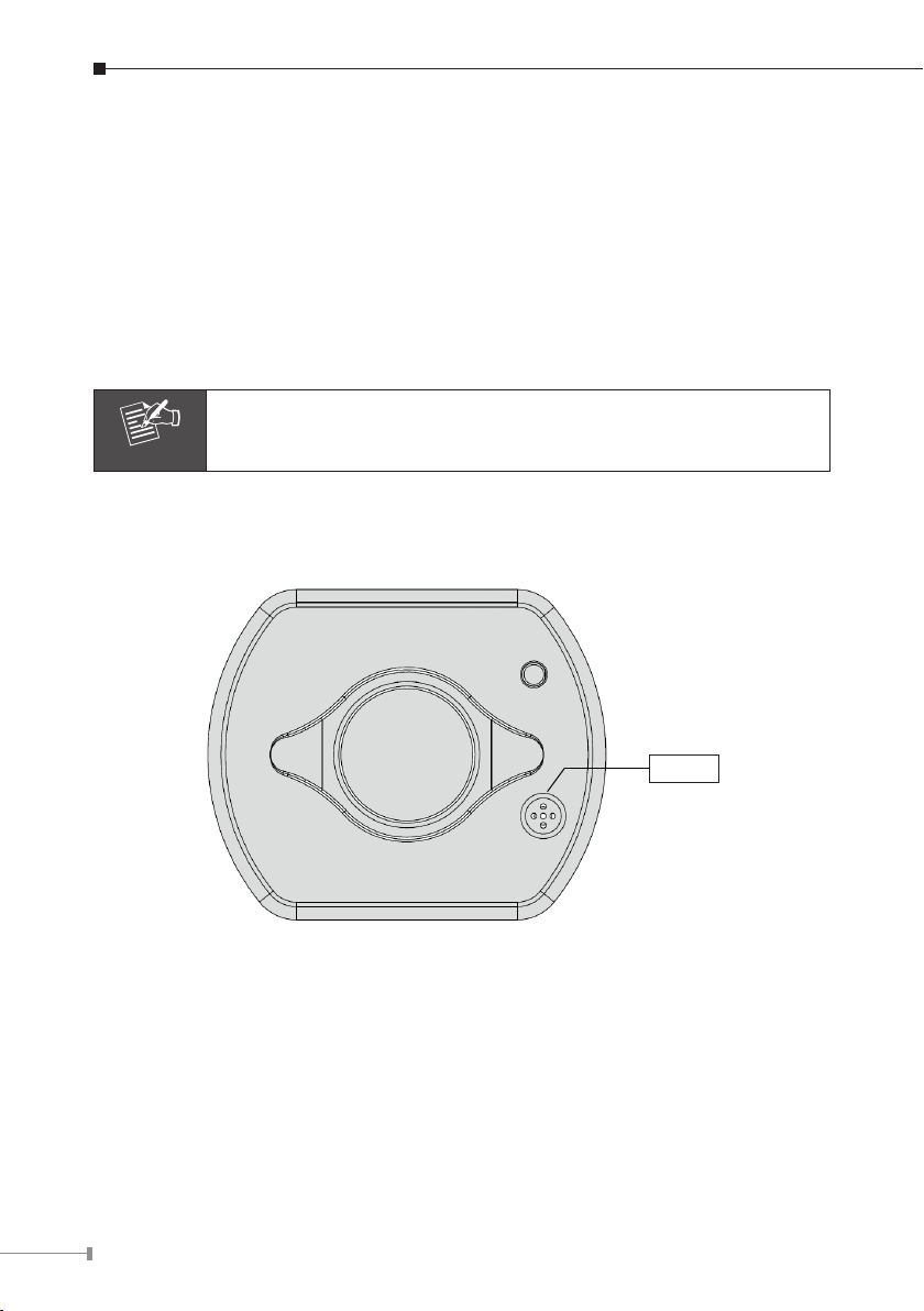
Rear View
1. MIC in:
The IP Camera has built-in an internal microphone. This microphone is hidden in
the pinhole located on the front panel.
2. DC-Iris:
The connector provides DC power can drive most DC-Iris lens for betterment of the
image quality.
3. Audio Output:
It allows this IP Camera to output audio. Connect with a 3.5Ø phone jack speaker
(external adaptor).
4. Video Out (BNC Connector):
The IP Camera also provides composite video output. User can use BNC video
cable to connect the IP Camera with a TV monitor or VCR.
4. Video Out
8. Reset Hole
9. SD Card Slot
5
Page 6

6
5. COM/GPIO:
Note
The 7 pin terminal block includes 2 input ports and 1 output ports.
Terminal block for I/O connectors:
Name Pin Function
COM 1 Signal output
Relay-ON 2 Signal output relay
GND 3 Ground
DI1 4 Signal Input 1
DI2 5 Signal Input 2
12V 6 DC 12V
GND 7 Ground
6. Power Jack:
The input power is DC 12V.
1. Only use the power adapter supplied with IP Camera otherwise,
the product may be damaged.
2. The power adapter is unnecessary when IP Camera is connected
to a IEEE 802.3af PoE switch. Otherwise, the product may be
damaged when IP Camera is connected to a PoE switch and
power adapter simultaneously.
7. LAN Socket:
The LAN socket is a RJ-45 connector for connections to 10/100Base-TX Fast
Ethernet cabling can detect or negotiate the transmission speed of the network
automatically. Please use CAT-5 or above cable to connect the IP Camera to a
100Mbps Fast Ethernet network switch or hub.
8. Reset Hole:
This button is hidden in the pinhole. Please refer to the user’s manual for more
information.
9. SD Card Slot:
The IP Camera has built-in an SD card slot accepts SD / SDHC memory card for
image / video event recording.
Page 7

2.3 ICA-HM125 Installation
Note
Note
å
é
ê
è
ç
Step 1. Prepare a PC with Ethernet link to the network
Step 2. Connect an Ethernet cable
Connect LAN port (RJ-45) of the IP Camera to a network switch. When
this switch is a PoE device, you can ignore the next step.
If there has an IEEE 802.3af PoE switch in your network, you
can connect the IP Camera LAN cable to this PoE switch to obtain
power. The power adapter is unnecessary when IP Camera is
connected to a PoE switch.
Step 3. Attach the power supply
Plug in power adapter to IP Camera and connect another end to power
outlet.
Only use the power adapter supplied with IP Camera otherwise, the
product may be damaged.
Step 4. Check LED status
The Power LED is dened to identify IP Camera status. When IP Camera
booting the LED will be ashing and while IP Camera is ready the LED will
be green.
Step 5. Attach BNC connector and speaker to IP Camera (option)
Connect the video BNC connector to a monitor set if necessary check IP
Camera viewing angle and focus. And if user needs not only video stream
but also audio stream, then the speaker should be attached to IP Camera.
7
Page 8

8
Chapter 3. Camera Windows Utility
This chapter shows how to quick set up your IP Camera. The IP Camera is with
the default settings. However to help you nd the networked IP Camera quickly
the Windows utility (PLANET IPInstaller) can search the IP Cameras in the network
that shall help you to congure some basic setting before you start advanced
management and monitoring.
Please insert the bundle CD disk into your CD/DVD-ROM drive. When the welcome
web page appears, please click your IP Camera name on the IP Camera list i.e.
ICA-HM125. Then click on the utility IPInstaller to start the program.
3.1 Network Conguration
Please click “Search Network Device” button. PLANET IPInstaller will list all
networked IP Camera in the LAN. If the IP Camera doesn’t be found, you may
check whether this IP Camera is connect to network properly and press the search
button again.
1. Click the menu bar Tool > Search Network Device
LAN.
to search the device in the
2. Select IP Camera with the MAC Address corresponds to the IP Camera that is to
be congured.
MAC Address
Page 9

3. Double click the item to open the Property Page or click the menu bar View >
Property.
4. After lling the desired settings in the properties, click on “Set” button to
complete the conguration settings.
9
Page 10

10
3.2 Open the Web-based UI
If IPInstaller nds IP Camera, please select the device you want to view and click
the “Open Web” button. Then you could see the video from IP Camera directly.
1. To access the Web-based UI of the selected unit, run the View > Open Web
the menu bar.
2. After connected to IP Camera, it will prompt for User Name and Password,
please enter both of admin to continue Web Management. Conrm the installa-
tion as it is required to view the video stream and some operations.
on
If difculty is met, please refer to the following steps to establish the connection:
- The IP Camera must be installed and powered ON.
- If the IP camera’s default IP Address
another device, the other device must be turned OFF until the device is allocated
a new IP Address during conguration.
(192.168.0.20) is already used by
Page 11

3. For the rst installation, there will be a prompt to install the ActiveX control.
4. If the device has been congured correctly, the default Web browser will open to
the home page of the selected device.
3.3 Setup ActiveX to use the IP Camera
If not able to get the ActiveX download properly, user must temporarily lower your
security settings to perform a one-time-only installation of the ActiveX component
onto your workstation, as described below:
1. From the
2. Set the security level to
3. Restore the security level after the ActiveX installation.
Tools menu, select Internet Options > Security > Custom Level.
“Low” and click “OK”.
11
Page 12

Further Information
This guide is used to help you startup your IP Camera settings. It is also
recommended to check the user manual in CD disk for more details of the system
and user conguration.
12
 Loading...