

Page 1

Wired / Wireless H.264 Internet Camera
Indoor Dome T ype
ICA-HM132
Outdoor Dome T ype
ICA-HM136 / ICA-5250V / ICA-5550V
Bullet T ype
ICA-HM316 / ICA-HM316W / ICA-3250V / ICA-3550V
Quick Installation Guide
Page 2

Table of Contents
1. Introduction ............................................................................................... 4
1.1 Before Installation ............................................................................... 4
1.2 System Requirements .......................................................................... 4
2. Physical Description and Installation ............................................................. 5
2.1 Indoor Dome Type – ICA-HM132 .......................................................... 5
2.1.1 Package Content ........................................................................ 5
2.1.2 Physical Details .......................................................................... 5
2.1.3 Installation ................................................................................ 6
2.2 Outdoor Dome Type – ICA-HM136 ........................................................ 7
2.2.1 Package Content ........................................................................ 7
2.2.2 Physical Details .......................................................................... 7
2.2.3 I/O Control Instruction ................................................................ 8
2.2.4 Installation ...............................................................................10
2.3 Outdoor Dome Type – ICA-5250V ........................................................10
2.3.1 Package Content .......................................................................10
2.3.2 Physical Details .........................................................................10
2.3.3 I/O Control Instruction ...............................................................11
2.3.4 Factory Default .........................................................................12
2.4 Outdoor Dome Type – ICA-5550V ........................................................13
2.4.1 Package Content .......................................................................13
2.4.2 Physical Details .........................................................................13
2.4.3 I/O Control Instruction ...............................................................14
2.4.4 Factory Default .........................................................................15
Page 3

2.5 Bullet Type – ICA-HM316 ....................................................................16
2.5.1 Package Content .......................................................................16
2.5.2 Physical Details .........................................................................16
2.5.3 Installation ...............................................................................17
2.6 Bullet Type – ICA-HM316W .................................................................18
2.6.1 Package Content .......................................................................18
2.6.2 Physical Details .........................................................................18
2.6.3 Installation ...............................................................................19
2.7 Bullet Type – ICA-3250V .....................................................................20
2.7.1 Package Content .......................................................................20
2.7.2 Physical Details .........................................................................20
2.7.3 Installation ...............................................................................21
2.8 Bullet Type – ICA-3550V .....................................................................23
2.8.1 Package Content .......................................................................23
2.8.2 Physical Details .........................................................................23
2.8.3 Installation ...............................................................................24
Chapter 3. Camera Windows Utility
3.1 IP Assignment ....................................................................................26
Further Information
........................................................................................30
..................................................................26
Page 4

4
1. Introduction
Thank you for purchasing PLANET Wired / Wireless IP Camera. It is versatile
and high image solution of surveillance application for day and night. PLANET
IP Camera supports, Multi-Prole function for simultaneous video streams.
These Network Cameras can generate H.264, MPEG-4 and M-JPEG streaming
simultaneously to different clients. Moreover, the resolution can be different from
one client to another. This state-of-art design is considerable to t in various
network environments.
This installation guide provides instructions for installing the following network
cameras:
l
ICA-HM132 – H.264 2 Mega-pixel 20M IR Vari-Focal Dome IP Camera
l
ICA-HM136 – H.264 2 Mega-pxel 20M IR Vandalproof Dome IP Camera
l
ICA-5250V – Full HD Vandalproof IR IP Camera
l
ICA-5550V – 5 Mega-pixel Vandalproof IR IP Camera
l
ICA-HM316 – 2 Mega-pixel Outdoor IR PoE IP Camera
l
ICA-HM316W – 2 Mega-pixel 11n Outdoor IR IP Camera
l
ICA-3250V – Full HD Outdoor IR PoE IP Camera
l
ICA-3550V – 5 Mega-pixel Outdoor IR PoE IP Camera
1.1 Before Installation
Before installation, please be sure to read this quick installation guide and user’s
manual (CD) carefully to complete machine installation. This guide shows how to
quickly set up the IP camera.
1.2 System Requirements
CPU Intel Core i3-530
RAM 2048MB
Graphic card 512MB
Display Resolution 1920 x 1200
Operating System Windows 2000, XP, 2003, Vista 32bit, Win7 32bit
Network Ethernet 10/100 Base-T
Page 5
5
2. Physical Description and Installation
2.1 Indoor Dome Type – ICA-HM132
2.1.1 Package Content
IP Camera Unit x 1 l
l
Power Adapter x 1
l
Screw Package x 1
l
User’s Manual CD-ROM x 1
l
Quick Installation Guide x 1
2.1.2 Physical Details
1. RJ-45 LAN socket: Connect to PC or Hub/Switch.
For connecting to 10Base-T Ethernet or 100Base-TX Fast Ethernet cable, this
Ethernet port built N-Way protocol can detect or negotiate the transmission speed
of the network automatically. Please use CAT-5 cable to connect the Network
Camera to a 100Mbps Fast Ethernet network switch or hub.
DC 12V / 1A
I/O Terminal
Video Output
Microphone Input (Pink)
Line Out (Green)
Network
2. I/O Control Instruction
I/O terminal connector is used for such functions as motion detection, event
triggering, and alarm alert. It provides the interface to I/O terminal.
3. Digital Input (GND + Alarm)
An alarm input for connecting devices can toggle between an open and closed
circuit, for example, PIRs, door/window contacts, glass break detectors, etc. When
a signal is received, the status changes and the input becomes active.
Page 6

6
4. Relay Output (COM+N.O.) / (COM+N.C.)
Note
An output to relay switch, for example, LEDs, sirens, etc.
5. Digital Input/Alarm Input
1) GND (Ground): Initial status is LOW
2) Alarm: Max. 50mA, 3.3VDC
6. Relay Output
1) N.C. (Normally Closed): Max. 1A, 24VDC or 0.2A, 110~240VAC
2) COM: (Common)
3) N.O. (Normally Open): Max. 1A, 24VDC or 0.2A, 110~240VAC
7. Power Jack
The input power is 12VDC.
To ensure maximum compatibility, use only the power adapter
that came with your product. Otherwise, the product may be
damaged.
8. MIC in (audio in)
Connect a microphone to the network camera.
9. Line Out (Audio Out)
Connect a loud speaker to the network camera. This is for voice alert and two-way
audio.
2.1.3 Installation
1. Fix IR camera in a desired location with stand.
2. Plug in Ethernet Cable into RJ-45 connector (LAN port).
3. Connect the attached power adapter to camera and plug in this adapter into
power outlet.
4. Connect Video BNC connector to a TV set if necessary (to check camera viewing
angle and focus).
5. Done.
Page 7

7
2.2 Outdoor Dome Type – ICA-HM136
Note
2.2.1 Package Content
Camera Unit x 1 l
l
Power Adapter x 1
l
Accessories Kit x 1
l
Female to Female RJ-45 Connector x 1
l
User’s Manual CD-ROM x 1
l
Quick Installation Guide x 1
2.2.2 Physical Details
1. RJ-45 LAN socket: Connect to PC or Hub/Switch.
For connecting to 10Base-T Ethernet or 100Base-TX Fast Ethernet cable, this
Ethernet port built N-Way protocol can detect or negotiate the transmission speed
of the network automatically. Please use CAT-5 cable to connect the Network
Camera to a 100Mbps Fast Ethernet network switch or hub.
2. Power Jack: The input power is 12VDC.
Power Jack
1. To ensure maximum compatibility, use only the power adapter
that came with your product. Otherwise, the product may be
damaged.
2. The RJ-45 port also supports IEEE 802.3af Power over Ethernet.
Apply either PoE or DC power to empower the IP camera and do
not use any other non-standard PoE injector to the camera.
RJ-45
Page 8
8
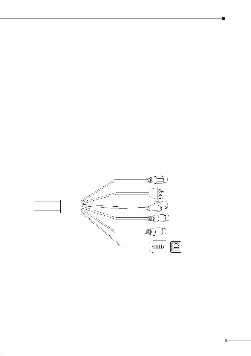
2.2.3 I/O Control Instruction
N.O
COM
N.C
GND
ALARM IN
AUDIO OUT
MIC IN
GND
VIDEO OUT
RELAY OUT
ALARM IN
I/O terminal connector is used for such functions as motion detection and event
triggering.
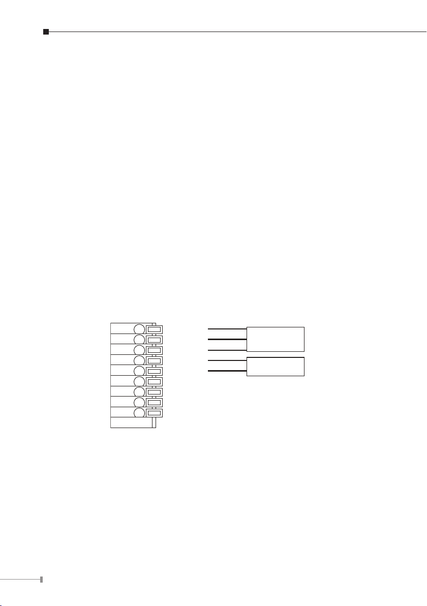
1. Digital Input: (GND+Alarm)
An alarm input for connecting devices can toggle between an open and closed
circuit, for example, PIRs, door/window contacts, glass break detectors, etc. When
a signal is received, the status changes and the input becomes active.
2. Relay Output: (COM+N.O.) / (COM+N.C.)
An output to relay switch, for example, LEDs, sirens, etc.
3. Digital Input/Alarm Input:
1) GND (Ground): Initial status is LOW
2) Alarm: Max. 50mA, 3.3VDC
4. Relay Output:
1) N.C. (Normally Closed): Max. 1A, 24VDC or 0.2A, 110~240VAC
2) COM: (Common)
3) N.O. (Normally Open): Max. 1A, 24VDC or 0.2A, 110~240VAC
Page 9
9
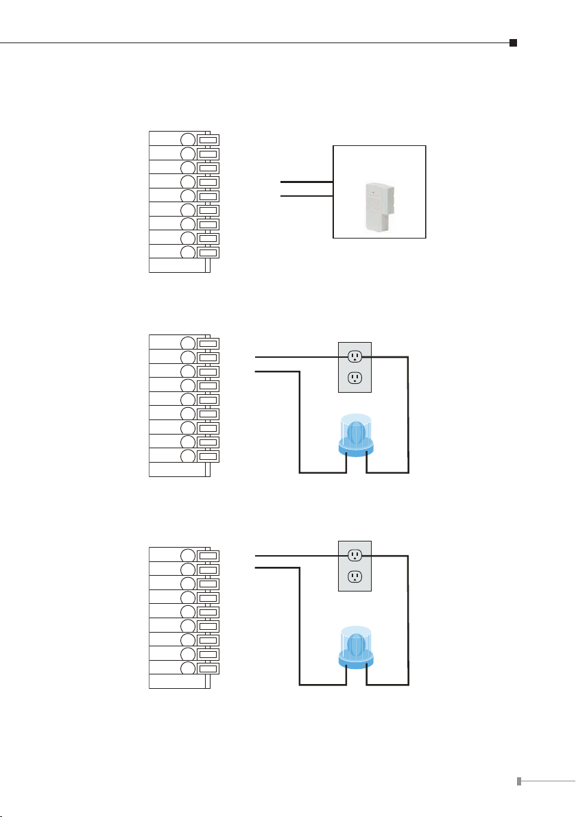
5. Relay Connection:
N.O
COM
N.C
GND
ALARM IN
AUDIO OUT
MIC IN
GND
VIDEO OUT
RELAY OUT
ALARM IN
N.O
COM
N.C
GND
ALARM IN
AUDIO OUT
MIC IN
GND
VIDEO OUT
Door/Window
Contacts IN
N.O
COM
N.C
GND
ALARM IN
AUDIO OUT
MIC IN
GND
VIDEO OUT
N.O
COM
N.C
GND
ALARM IN
AUDIO OUT
MIC IN
GND
VIDEO OUT
RELAY OUT
ALARM IN
N.O
COM
N.C
GND
ALARM IN
AUDIO OUT
MIC IN
GND
VIDEO OUT
Door/Window
Contacts IN
N.O
COM
N.C
GND
ALARM IN
AUDIO OUT
MIC IN
GND
VIDEO OUT
N.O
COM
N.C
GND
ALARM IN
AUDIO OUT
MIC IN
GND
VIDEO OUT
N.O
COM
N.C
GND
ALARM IN
AUDIO OUT
MIC IN
GND
VIDEO OUT
RELAY OUT
ALARM IN
N.O
COM
N.C
GND
ALARM IN
AUDIO OUT
MIC IN
GND
VIDEO OUT
Door/Window
Contacts IN
1) Digital Input connection
2) Relay Output Connection
Or
Page 10

10
6. MIC IN:
Connect a microphone to the network camera.
7. AUDIO OUT
Connect a loud speaker to the network camera. This is for voice alert and two-way
audio.
2.2.4 Installation
1. Fix IR camera in a desired location with stand.
2. Plug in Ethernet Cable into RJ-45 connector (LAN port).
3. Connect the attached power adapter to camera and plug in this adapter into power
outlet.
4. Connect Video BNC connector to a TV set if necessary (to check camera viewing
angle and focus).
5. Done.
2.3 Outdoor Dome Type – ICA-5250V
2.3.1 Package Content
Camera Unit x 1 l
l
Power Adapter x 1
l
Accessories Kit x 1
l
Female to Female RJ-45 Connector x 1
l
Mounting Label x 1
l
User’s Manual CD-ROM x 1
l
Quick Installation Guide x 1
2.3.2 Physical Details
1. RJ-45 LAN socket: Connect to PC or Hub/Switch.
For connecting to 10Base-T Ethernet or 100Base-TX Fast Ethernet cable, this
Ethernet port built N-Way protocol can detect or negotiate the transmission speed
of the network automatically. Please use CAT-5 cable to connect the Network
Camera to a 100Mbps Fast Ethernet network switch or hub.
Page 11

11
2. Power Jack: The input power is 12VDC.
Note
RJ45
Micro SD
DEFAULT
DC
GND
GND
DO
DI
Line_OUT
MIC_IN
GND
VIDEO
Power Jack
RJ-45
1. To ensure maximum compatibility, use only the power adapter
that came with your product. Otherwise, the product may be
damaged.
2. The RJ-45 port also supports IEEE 802.3af Power over Ethernet.
Apply either PoE or DC power to empower the IP camera and do
not use any other non-standard PoE injector to the camera.
2.3.3 I/O Control Instruction
I/O terminal connector is used for such functions as motion detection, and event
triggering.
Page 12

12
2.3.3.1 I/O Connection
Please connect the GND & DO pin to the external relay (buzzer) device.
Please connect the GND & DI pin to the external trigger device.
2.3.3.2 I/O PIN denition
◊ GND (Ground): Initial status is LOW
◊ DO (Digital Output): 5VDC
◊ DI (Digital Input): Max. 50mA, 5VDC
2.3.4 Factory Default
If you forget your password, please follow the steps to revert back to default
value.
1. Remove the power and Ethernet cable. Press and hold the button as shown in
the picture below.
2. Connect power to the camera again, and do not release the button during the
system booting.
Page 13

13
3. It will take around 30 seconds to boot the camera.
4. Release the button when camera nishes proceed.
5. Plug in the Ethernet cable, and re-login the camera using the default IP
(http://192.168.0.20), and user name (admin), password (admin).
2.4 Outdoor Dome Type – ICA-5550V
2.4.1 Package Content
Camera Unit x 1 l
l
Power Adapter x 1
l
Accessories Kit x 1
l
Female to Female RJ-45 Connector x 1
l
Mounting Label x 1
l
User’s Manual CD-ROM x 1
l
Quick Installation Guide x 1
2.4.2 Physical Details
1. RJ-45 LAN socket: Connect to PC or Hub/Switch.
For connecting to 10Base-T Ethernet or 100Base-TX Fast Ethernet cable, this
Ethernet port built N-Way protocol can detect or negotiate the transmission speed
of the network automatically. Please use CAT-5 cable to connect the Network
Camera to a 100Mbps Fast Ethernet network switch or hub.
2. Power Jack: The input power is 12VDC.
Power Jack
RJ-45
Page 14

14
Note
1. To ensure maximum compatibility, use only the power adapter
RJ45
Micro SD
DEFAULT
DC
GND
GND
DO
DI
Line_OUT
MIC_IN
GND
VIDEO
that came with your product. Otherwise, the product may be
damaged.
2. The RJ-45 port also supports IEEE 802.3af Power over Ethernet.
Apply either PoE or DC power to empower the IP camera and do
not use any other non-standard PoE injector to the camera.
2.4.3 I/O Control Instruction
I/O terminal connector is used for such functions as motion detection and event
triggering.
2.4.3.1 I/O Connection
Please connect the GND & DO pin to the external relay (buzzer) device.
Please connect the GND & DI pin to the external trigger device.
Page 15

15
2.4.3.2 I/O PIN denition
◊ GND (Ground): Initial status is LOW
◊ DO (Digital Output): 5VDC
◊ DI (Digital Input): Max. 50mA, 5VDC
2.4.4 Factory Default
If you forget your password, please follow the steps to revert back to default
value.
1. Remove the power and Ethernet cable. Press and hold the button as shown in
the picture below.
2. Connect power to the camera again, and do not release the button during the
system booting.
3. It will take around 30 seconds to boot the camera.
4. Release the button when camera nishes proceed.
5. Plug in the Ethernet cable, and re-login the camera using the default IP
(http://192.168.0.20), and user name (admin), password (admin).
Page 16

16
2.5 Bullet Type – ICA-HM316
2.5.1 Package Content
IP Camera Unit x 1 l
l
Power Adapter x 1
l
Screw Package x 1
l
Stand x 1
l
User’s Manual CD-ROM x 1
l
Quick Installation Guide x 1
2.5.2 Physical Details
1. RJ-45 LAN socket: Connect to PC or Hub/Switch.
For connecting to 10Base-T Ethernet or 100Base-TX Fast Ethernet cable, this
Ethernet port built N-Way protocol can detect or negotiate the transmission speed
of the network automatically. Please use CAT-5 cable to connect the Network
Camera to a 100Mbps Fast Ethernet network switch or hub.
DC 12V / 1A
I/O Terminal
Video Output
Microphone Input (Pink)
Line Out (Green)
Network
2. I/O Control Instruction
I/O terminal connector is used for such functions as motion detection, event
triggering, and alarm alert. It provides the interface to I/O terminal.
3. Digital Input (GND + Alarm)
An alarm input for connecting devices can toggle between an open and closed
circuit, for example, PIRs, door/window contacts, glass break detectors, etc. When
a signal is received, the status changes and the input becomes active.
Page 17

17
4. Relay Output (COM+N.O.) / (COM+N.C.)
Note
An output to relay switch, for example, LEDs, sirens, etc
5. Digital Input/Alarm Input
1) GND (Ground): Initial status is LOW
2) Alarm: Max. 50mA, 3.3VDC
6. Relay Output
1) N.C. (Normally Closed): Max. 1A, 24VDC or 0.2A, 110~240VAC
2) COM: (Common)
3) N.O. (Normally Open): Max. 1A, 24VDC or 0.2A, 110~240VAC
7. Power Jack
The input power is 12VDC.
To ensure maximum compatibility, use only the power adapter that
came with your product. Otherwise, the product may be damaged.
8. MIC in (audio in)
Connect a microphone to the network camera.
9. Line out (audio out)
Connect a loud speaker to the network camera. This is for voice alert and two-way
audio.
2.5.3 Installation
1. Fix IR camera in a desired location with stand.
2. Plug in Ethernet Cable into RJ-45 connector (LAN port).
3. Connect the attached power adapter to camera and plug in this adapter into
power outlet.
4. Connect Video BNC connector to a TV set if necessary (to check camera viewing
angle and focus).
5. Done.
Page 18

18
2.6 Bullet Type – ICA-HM316W
2.6.1 Package Content
IP Camera Unit x 1 l
l
Power Adapter x 1
l
Screw Package x 1
l
Stand x 1
l
5dbi Antenna x 1
l
User’s Manual CD-ROM x 1
l
Quick Installation Guide x 1
2.6.2 Physical Details
1. RJ-45 LAN socket: Connect to PC or Hub/Switch.
For connecting to 10Base-T Ethernet or 100Base-TX Fast Ethernet cable, this
Ethernet port built N-Way protocol can detect or negotiate the transmission speed
of the network automatically. Please use CAT-5 cable to connect the Network
Camera to a 100Mbps Fast Ethernet network switch or hub.
2. I/O Control Instruction
I/O terminal connector is used for such functions as motion detection, event
triggering, and alarm alert. It provides the interface to I/O terminal.
3. Digital Input (GND + Alarm)
An alarm input for connecting devices can toggle between an open and closed
circuit, for example, PIRs, door/window contacts, glass break detectors, etc. When
a signal is received, the status changes and the input becomes active.
4. Relay Output (COM+N.O.) / (COM+N.C.)
An output to relay switch, for example, LEDs, sirens, etc.
5. Digital Input/Alarm Input
1) GND (Ground): Initial status is LOW
2) Alarm: Max. 50mA, 3.3VDC
6. Relay Output
1) N.C. (Normally Closed): Max. 1A, 24VDC or 0.2A, 110~240VAC
2) COM: (Common)
3) N.O. (Normally Open): Max. 1A, 24VDC or 0.2A, 110~240VAC
Page 19

19
7. Power Jack
Note
The input power is 12VDC.
DC 12V / 1A
I/O Terminal
Video Output
Microphone Input (Pink)
Line Out (Green)
Network
To ensure maximum compatibility, use only the power adapter that
came with your product. Otherwise, the product may be damaged.
8. MIC in (audio in)
Connect a microphone to the network camera.
9. Line out (audio out)
Connect a loud speaker to the network camera. This is for voice alert and two-way
audio.
2.6.3 Installation
1. Fix IR camera in a desired location with stand.
2. Plug in Ethernet Cable into RJ-45 connector (LAN port).
3. Connect the attached power adapter to camera and plug in this adapter into power
outlet.
4. Connect Video BNC connector to a TV set if necessary (to check camera viewing
angle and focus).
5. Done.
Page 20

20
2.7 Bullet Type – ICA-3250V
2.7.1 Package Content
IP Camera Unit x 1 l
l
Power Adapter x 1
l
Screw Package x 1
l
Female to Female RJ-45 Connector x 1
l
User’s Manual CD-ROM x 1
l
Quick Installation Guide x 1
2.7.2 Physical Details
1. RJ-45 LAN socket: Connect to PC or Hub/Switch.
For connecting to 10Base-T Ethernet or 100Base-TX Fast Ethernet cable, this
Ethernet port built N-Way protocol can detect or negotiate the transmission speed
of the network automatically. Please use CAT-5 cable to connect the Network
Camera to a 100Mbps Fast Ethernet network switch or hub.
I/O Terminal
DC 12V / 1A
Line Out (Green)
Microphone Input (Pink)
Network
Video Output
2. I/O Control Instruction
I/O terminal connector is used for such functions as motion detection, event
triggering, and alarm alert. It provides the interface to I/O terminal.
Page 21

21
3. Digital Input / Output
Note
ROTATION:360˚
TILT:180˚
PAN:360˚
Note
1) GND (Ground): Initial status is LOW
2) DI (Digital Input): Max. 50mA, 5VDC
3) DO (Digital Output): 5VDC
4. Power Jack
The input power is 12VDC.
5. MIC In (Audio In)
Connect a microphone to the network camera.
6. Line Out (Audio Out)
Connect a loud speaker to the network camera. This is for voice alert and two-way
audio.
7. Reset to default
Take an electronic wire, plug one side of the wire into “Default” and the other side
into “GND”.
To ensure maximum compatibility, use only the power adapter that
came with your product. Otherwise, the product may be damaged.
2.7.3 Installation
1. You can use 3-Axis bracket to adjust the angle of camera. Please lock the screws
tightly to x the angle after adjusting.
Please take note of the cable situation. Avoid excessive distortions
in the cable; otherwise, it will cause malfunction.
Page 22

22
2. Plug in Ethernet Cable into RJ45 connector (LAN port).
ZOOM
FOCUS
Screw them tightly
Note
3. Connect the attached power adapter to camera and plug in this adapter into
power outlet.
4. Connect Video BNC connector to a TV set if necessary (to check camera viewing
angle and focus).
5. This IP camera is equipped with an external vari-focal lens controller. Please
adjust “ZOOM” and then “FOCUS” as shown in the following picture until the
image gets clear.
6. For the waterproof reason, if you install a Micro SD card, please turn and lock
the screws on the Micro SD card lid tightly and make sure it’s sealed.
7. Done.
Be aware the waterproof rubber, improper placement or missing the
rubber will cause seal malfunction.
Page 23

23
2.8 Bullet Type – ICA-3550V
2.8.1 Package Content
IP Camera Unit x 1 l
l
Power Adapter x 1
l
Screw Package x 1
l
Female to Female RJ-45 Connector x 1
l
User’s Manual CD-ROM x 1
l
Quick Installation Guide x 1
2.8.2 Physical Details
1. RJ-45 LAN socket: Connect to PC or Hub/Switch.
For connecting to 10Base-T Ethernet or 100Base-TX Fast Ethernet cable, this
Ethernet port built N-Way protocol can detect or negotiate the transmission speed
of the network automatically. Please use CAT-5 cable to connect the Network
Camera to a 100Mbps Fast Ethernet network switch or hub.
I/O Terminal
DC 12V / 1A
Line Out (Green)
Microphone Input (Pink)
Network
Video Output
2. I/O Control Instruction
I/O terminal connector is used for such functions as motion detection, event
triggering, and alarm alert. It provides the interface to I/O terminal.
Page 24

24
3. Digital Input / Output
Note
ROTATION:360˚
TILT:180˚
PAN:360˚
Note
1) GND (Ground): Initial status is LOW
2) DI (Digital Input): Max. 50mA, 5VDC
3) DO (Digital Output): 5VDC
4. Power Jack
The input power is 12VDC.
5. MIC In (Audio In)
Connect a microphone to the network camera.
6. Line Out (Audio Out)
Connect a loud speaker to the network camera. This is for voice alert and two-way
audio.
7. Reset to default
Take an electronic wire, plug one side of the wire into “Default” and the other side
into “GND”.
To ensure maximum compatibility, use only the power adapter that
came with your product. Otherwise, the product may be damaged.
2.8.3 Installation
1. You can use 3-Axis bracket to adjust the angle of camera. Please lock the screws
tightly to x the angle after adjusting.
Please take note of the cable situation. Avoid excessive distortions
in the cable; otherwise, it will cause malfunction.
Page 25

25
2. Plug in Ethernet Cable into RJ45 connector (LAN port).
ZOOM
FOCUS
Screw them tightly
Note
3. Connect the attached power adapter to camera and plug in this adapter into
power outlet.
4. Connect Video BNC connector to a TV set if necessary (to check camera viewing
angle and focus).
5. This IP camera is equipped with an external vari-focal lens controller. Please
adjust “ZOOM” and then “FOCUS” as shown in the following picture until the
image gets clear.
6. For the waterproof reason, if you install a Micro SD card, please turn and lock
the screws on the Micro SD card lid tightly and make sure it’s sealed.
7. Done.
Be aware the waterproof rubber, improper placement or missing the
rubber will cause seal malfunction.
Page 26

26
Chapter 3. Camera Windows Utility
This chapter shows how to quickly set up your PLANET IP Camera. The PLANET
IP Camera is with the default settings. However, to help you nd the networked
camera quickly, the windows utility (PLANET IP Installer) can search the cameras
in the network that will help you to congure some basic setting before you start
advanced management and monitoring.
Please insert the bundle CD disk into your CD/DVD-ROM drive. When the welcome
web page appears, please click your IP camera name on the IP camera list. Then
click the PLANET IPInstaller hyperlink to start the PLANET IP Installer.
3.1 IP Assignment
1. Use “IP Installer II” to assign an IP address of IP CAMERA.
The IP Installer software is in the attached CD.
2. IP Installer supports languages.
IPInstallerEng.exe
3. OS: Windows XP SP2 or above. If the following “Windows Security
Alert” popup, please click “Unblock”.
Page 27

27
4. The GUI of IP Installer is as follows (Default IP: 192.168.0.20).
IP Installer will search all IP Cameras connected on LAN. The user can click l
“Search Device” to search again.
l
Click one of IP Cameras listed on the left side of IP Installer, then the network
conguration of that IP Camera will be listed on the right side. If parameters
change, click on “Submit”. Then, the network conguration will be changed.
Just click “OK” to reboot.
Please make sure the subnet of PC IP address and IP CAM IP address are the l
same.
For Example:
IP CAM IP address: 192.168.0.20
PC IP address: 192.168.0.100
Page 28

28
To Change PC IP addresses:
Control Panel Network Connections Local Area Connection Properties
Internet Protocol (TCP/IP) Properties
Please make sure your IP Camera and PC have the same Subnet. If not, please
change IP Camera IP subnet or PC IP subnet accordingly .
A quick way to access remote monitoring is to left-click the mouse twice on a l
selected IP Camera listed on “Device list” of IP Installer. An IE browser will be
opened.
l “Username: admin” and “Password: admin”
Then, please key in the default
in the following message box.
Page 29

29
If the user name and password are input correctly, the following web page will l
be displayed.
Page 30

Further Information
This guide is used to help you start-up your IP Camera settings. It is also
recommended to check the user manual in CD disk for more details of the system
and user conguration.
30
Page 31

This page is intentionally left blank
Page 32

This page is intentionally left blank
 Loading...