

Page 1

Industrial PoE Plus Outdoor IR IP Camera
ICA-2250VT
Quick Installation Guide
Page 2

Table of Contents
Chapter 1. Introduction .................................................................................... 3
1.1 Before Installation ............................................................................... 3
1.2 System Requirements .......................................................................... 3
Chapter 2. Physical Description and Installation
2.1 ICA-2250VT Package Contents .............................................................. 4
2.2 ICA-2250VT Physical Details ................................................................. 4
2.3 ICA-2250VT Installation ....................................................................... 6
Chapter 3. Camera Windows Utility
Further Information
........................................................................................14
..................................................................10
.................................................. 4
Page 3

Chapter 1. Introduction
Thank you for purchasing the PLANET Industrial PoE Plus Outdoor IR IP Camera.
It is versatile and high image solution of surveillance application for day and
night. PLANET ICA-2250VT IP Camera supports multi-prole function that can play
simultaneous video streams. This network camera can generate H.264, MPEG-4
and M-JPEG streaming simultaneously for different clients. Moreover, the resolution
can be different from one client to another. This state-of-art design is considerable
to t in various network environments.
1.1 Before Installation
Before installation, please be sure to read this quick installation guide and user’s
manual (CD) carefully to complete machine installation. This guide shows how to
quickly set up this camera.
1.2 System Requirements
CPU Intel CPU: Intel Core i3-530
RAM 2GB (recommended above)
Video RAM 512MB (recommended above)
Display Resolution 1920 x 1200
Monitoring System Recommended for Internet Explorer 8.0 or later
Operating System Windows XP / Win7
DirectX 10 or above
Network Wired Ethernet 100Base-TX
3
Page 4
4
Chapter 2. Physical Description and Installation
Note
Note
2.1 ICA-2250VT Package Contents
ICA-2250VT x 1 l
Wall Mounter x 1
l
Wall Mounting Kit x 1
l
User’s Manual CD x 1
l
Quick Installation Guide x 1
l
If any of the above items are missing, please contact your dealer
immediately .
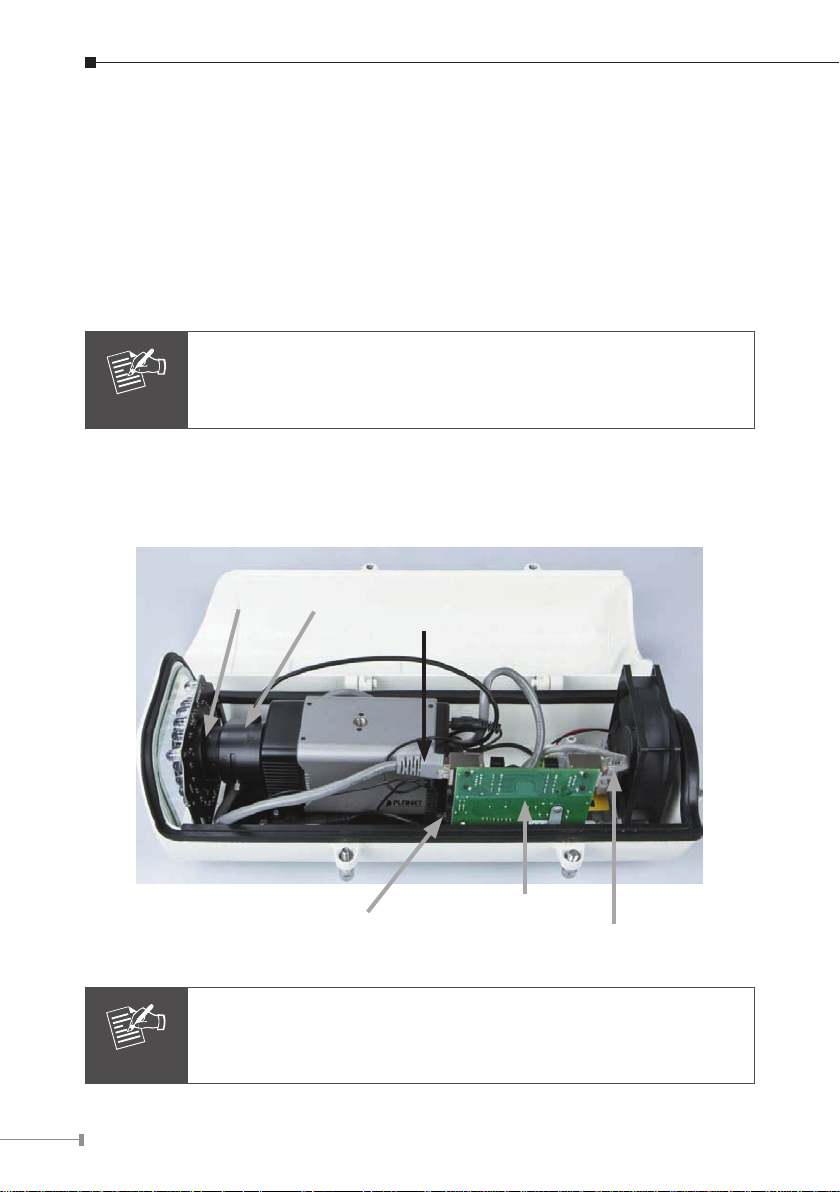
2.2 ICA-2250VT Physical Details
Inside View of ICA-2250VT
Focus adjust
Provide power to camera, heater,
IR LED and blower
Please don’t change cable to avoid camera malfunction if necessary
Zoom adjust
Connect to LAN of camera
802.3at PoE module
PoE power supply from
802.3at PoE switch
Page 5
5
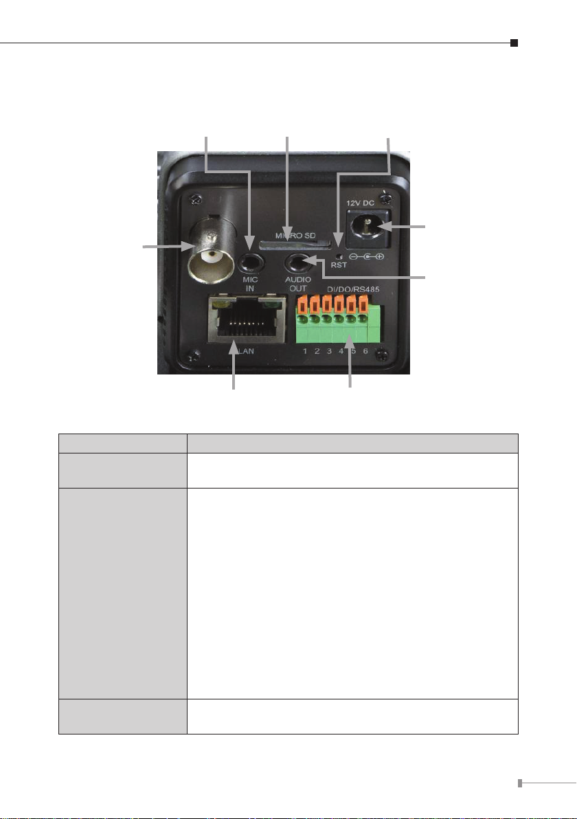
Rear View
Microphone in
Video out
LAN connector
Interface Description
DC Power
(Power Jack)
LAN
(RJ-45 socket)
The input power is DC 12V, 1A.
Note: The power supply from 802.3at PoE module.
Connect to PC or Switch. (For connection to 10Base-T,
100Base-TX or 1000Base-T Ethernet cabling)
This Ethernet port built auto-negotiation protocol can
detect or negotiate the transmission speed of the network
automatically. Please use CAT-5 cable to connect the
Network Camera to a 100Mbps Fast Ethernet network
switch or hub.
Power LED (orange color)
This LED is used to indicate whether DC power is on or
not.
LAN LED (green color)
This LED will be ashing while network accessing via
Ethernet.
Micro SD
card slot
DI/DO connector
Reset button
Power jack
Audio out
Audio Out
(Audio Output)
Connect a loud speaker to the IP Camera. This is for
voice alerting and two-way audio.
Page 6

6
Mic In
(Microphone Input)
Micro SD
(Micro SD Card Slot)
BNC Connector
(Video Output)
Connect a microphone to the IP Camera.
User can insert a micro SD card into this slot for
recording.
The Network Camera also provides composite video
output. The video output function is only for easy
installation to check view angle and focus. Furthermore,
only “720P Mode” supports this function.
RST
(Factory Default)
DI/DO, RS-485
The Camera provides a terminal block with 6 pins of connectors for DI, DO, and
RS485. Please refer below for more information.
Name Number Function
12V DC 1 DC 12V (50mA maximum)
DI 2 Digital signal input
GND 3 GND
DO 4 Digital signal output
485+ 5 RS485 data +
485- 6 RS485 data -
This button is used to restore all the factory default
settings.
The 6-pin terminal block includes 1 input port and 1
output port, and RS-485 D+ and D-.
2.3 ICA-2250VT Installation
2.3.1 Take out the ICA-2250VT from the package.
Page 7

7
2.3.2 Use the wrench from the wall mounting kit to counterclockwise release the
screw and protective cap.
Counterclockwise
release screw
Counterclockwise
release protective cap
LAN cable in
I/O, Audio cable
out (Optional)
2.3.3 Slide an RJ-45 cable without its plug through the stand and the protective
cap. Then x the RJ-45 plug and connect it to the connector of the PoE
module. Please note that the whole RJ-45 cable (with the plug) cannot go
through the protective cap. When the setup is completed, user can use PoE
tester to test PoE module to check whether the LED works or not.
PoE Module
Stand
From 802.3at PoE Switch
Protective Cap
Page 8

8
2.3.4 Use the wrench from the wall mounting kit to clockwise tighten the screw
Note
and protective cap.
Clockwise tighten
screw
Clockwise tighten
protective cap
Two screws of shield will effects camera’s waterproof. Please notice
it.
2.3.5 Use the wrench to tighten the four screws.
Page 9

9
2.3.6 After the above steps have been done, place the ICA-2250VT on the wall
Note
with the four screws tightened.
Please make sure the hardware had been located on the wall
properly. If the hardware drops down, it is possible make someone
injury or hurt. Please check the hardware again after the installation.
2.3.7 Now connect it to 802.3at PoE switch by means of the LAN socket located
on the ICA-2250VT’s back panel via an Ethernet cable to enable to power up
the operation.
2.3.8 Through the search utility, use PLANET IPWizard II to get the IP of the
ICA-2250VT and use browser to connect the ICA-2250VT to the Web.
2.3.9 Adjust zoom and focus of the camera to get a perfect video.
2.3.10 Done.
Page 10

10
Chapter 3. Camera Windows Utility
This chapter shows how to quickly set up your Industrial PoE Plus Outdoor IR IP
Camera. The Industrial PoE Plus Outdoor IR IP Camera is with the default settings.
However, to help you nd the networked camera quickly, the windows utility
(PLANET IPWizard II) can search the IP cameras in the network that can help
you to congure some basic setting before you start advanced management and
monitoring.
Please insert the bundled CD disk into your CD/DVD-ROM drive. When the welcome
web page appears, please click your IP camera name on the IP camera list. Then
click the PLANET IPWizard II hyperlink to start the PLANET IPWizard II.
Search function:
Press “Search” button. PLANET IPWizard II will list all networked devices in the
LAN. If the IP camera cannot be found, you may check whether this IP camera is
connected to network properly and press the Search button again.
Page 11

11
View function:
If PLANET IPWizard II nds network devices, View button will be available. Please
select the device you want to view and click the View button. Furthermore,
you could double-click the left button of mouse to link to the network device by
browser.
LAN setting:
The utility featured with “LAN” setting function is to help user to modify the
IP parameters of the installed network devices. User can step by step set up IP
address, user name and password.
Page 12

12
Note
1. If no IP address is assigned within 30 seconds, the networked
device will automatically assign 192.168.0.20. User may now
open your web browser, and key in http://192.168.0.20 in
the address bar of your web browser to log-on IP Camera’s web
configuration page.
2. Power Line Frequency
- If you find the video image is flashing, you may need to
choose 50 or 60Hz frequency (depending on the country).
- The worldwide power line frequency table is inside user’s
manual under Appendix.
Page 13

13
After being connected to networked device, the device will prompt for User Name
and Password. For the rst time, please enter: admin as user name and password
to continue Web Management.
Default User Name: admin
Default Password: admin
Default IP: 192.168.0.20 – if no DHCP existed in the network
If difculty is met, please refer to the following steps to establish the connection:
- The networked device must be installed and powered ON.
If the networked device’s default IP Address (192.168.0.20) is already used by
another device, the other device must be turned OFF until the device is allocated a
new IP Address during conguration.
Page 14

Further Information
This guide is used to help you start up your IP Camera settings. It is also
recommended to check the user manual in CD disk for more details of the system
and user conguration.
14
Page 15

This page is intentionally left blank
Page 16

This page is intentionally left blank
 Loading...