

Page 1

Dual Mode Internet Camera
ICA-151 / ICA-750
Quick Installation Guide
Page 2

Table of Contents
Chapter 1. Introduction .................................................................................... 3
1.1 Before Installation ................................................................................. 3
Chapter 2. ICA-151 – Dual Mode CMOS IP Camera ............................................ 4
2.1 Package Content ................................................................................... 4
2.2 Outlook ................................................................................................ 4
2.2.1 Front Panel ................................................................................. 4
2.2.2 Rear Panel .................................................................................. 5
2.3 Physical Installation ............................................................................. 6
Chapter 3. ICA-750 Dual Mode CCD Box IP Camera ........................................... 7
3.1 Package Content ................................................................................... 7
3.2 Outlook ................................................................................................ 7
3.2.1 Front Panel ................................................................................. 7
3.2.2 Rear Panel .................................................................................. 8
3.3 Physical Installation ............................................................................... 8
Chapter 4. Setup Wizard Installation and operation ............................................ 9
Chapter 5. Cam Viewer Plus Installation ...........................................................16
Appendix A: Feature Listing for Cam Viewer Plus ...............................................21
Appendix B: Suggest Hardware / System Requirement ......................................22
Ordering Information for Cam Viewer Plus Pro .............................................23
Further Conguration .................................................................................23
Page 3

Chapter 1. Introduction
Thank you for purchasing the IP surveillance product. It is versatile and high image
solution of the perfect surveillance application. The IP surveillance state-of-art
design is considerable to t in various network environments.
1.1 Before Installation
Before installation, please be sure to read this quick installation guide and user’s
manual (CD) carefully to complete machine installation.
This QIG includes the following chapter:
• Chapter 2. ICA-151 – Dual Mode CMOS IP Camera
• Chapter 3. ICA-750 – Dual Mode CCD Box IP Camera
• Chapter 4. Setup Wizard Installation and operation
• Chapter 5. Cam Viewer Plus Installation
• Appendix A: Feature Listing for Cam Viewer Plus
• Appendix B: Suggest Hardware / System Requirement
3
Page 4
4
Chapter 2. ICA-151 – Dual Mode CMOS IP Camera
Note
2.1 Package Content
ICA-151 x 1
Power Adapter x 1
Camera Stand x 1
CD Disk x 1
Quick Installation Guide x 1
1. If any of the above items are missing, please contact your
dealer immediately.
2. Using a power supply with a different voltage that the one
included with the package will cause damage and void the
warranty.
2.2 Outlook
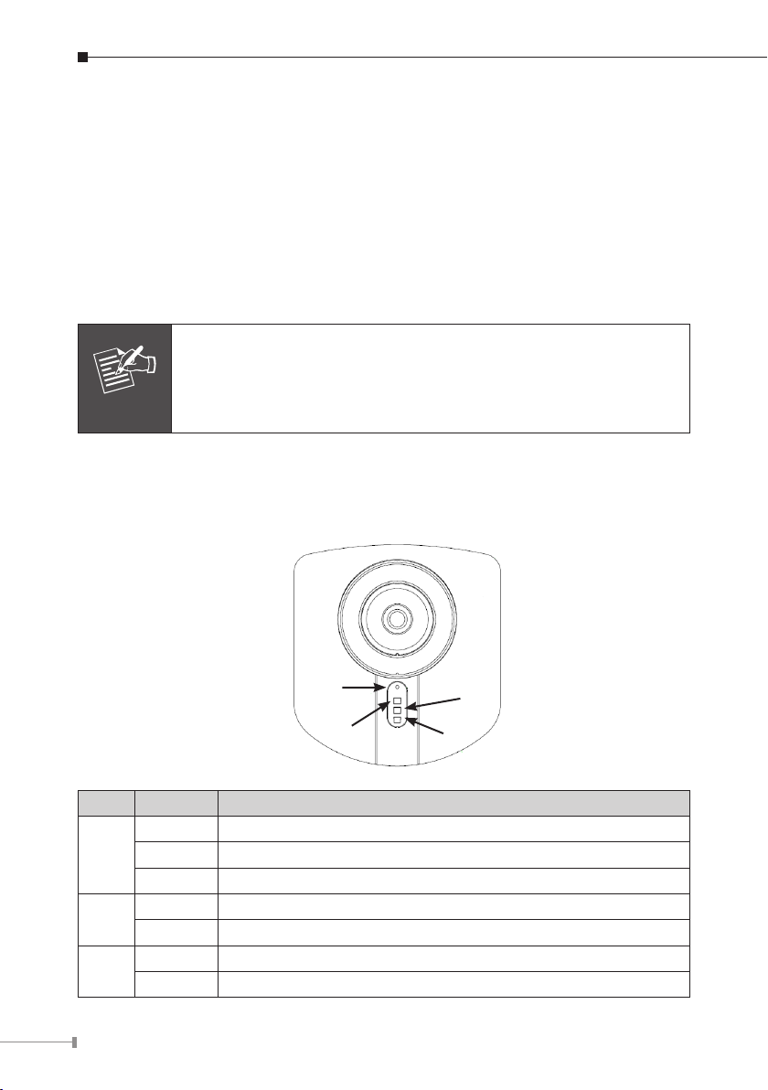
2.2.1 Front Panel
Microphone
PWR
ACT
LAN
LED Status LED Description
Off No power.
PWR
ACT
LAN
On Power on.
Blinking The Power LED will blink during start up (15 ~ 20 sec).
Off Camera is not capturing video.
Blinking Camera is capturing video.
Off LAN is not connected or camera is not sending/receiving data.
Blinking Data is being transmitted or received via the LAN connection.
Page 5
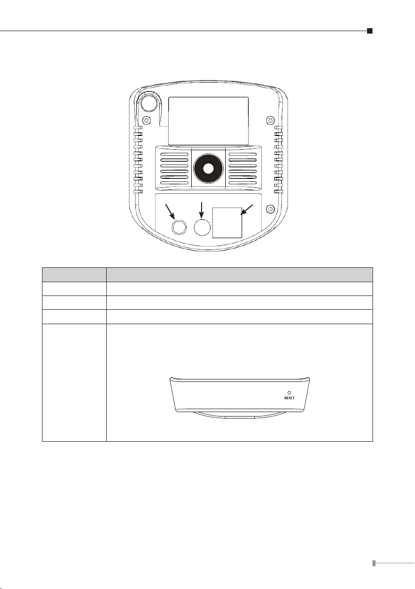
2.2.2 Rear Panel
AUDIO OUT
PWR
LAN
PORT PORT Description
AUDIO OUT An external speaker can be plugged in.
PWR Connect the supplied power adapter.
LAN Connect your Camera to a 10/100Base-TX hub or switch.
Reset to manufacturer default valued and reboot.
When pressed and held over 10 seconds, the settings of IP
Camera will be set to the default values.
Upon completion, the PWE LED will blink three times.
Reset
Bottom Panel of ICA-151
5
Page 6

6
2.3 Physical Installation
1. Connect an Ethernet cable
Connect one end of an Ethernet cable to the LAN port located on the IP camera’s
rear panel and connect the other end to the network device (hub or switch).
2. Attach the external power supply
Attach the provided power adapter to the IP camera’s connector labeled “PWR”
on the rear panel.
3. Check the LEDs
a. The Power LED will turn on briey, and then start blinking during startup.
After startup is completed, the Power LED will remain ON.
b. The LAN LED will be ON.
Page 7
Chapter 3. ICA-750 Dual Mode CCD Box IP Camera
Note
3.1 Package Content
ICA-750 x 1
Power Adapter x 1
CD Disk x 1
Quick Installation Guide x 1
Allen Wrench x 1
Camera Stand x 1
1. if any of the above items are missing, please contact your dealer
immediately.
2. Using a power supply with a different voltage that the one
included with the package will cause damage and void the
warranty.
3.2 Outlook
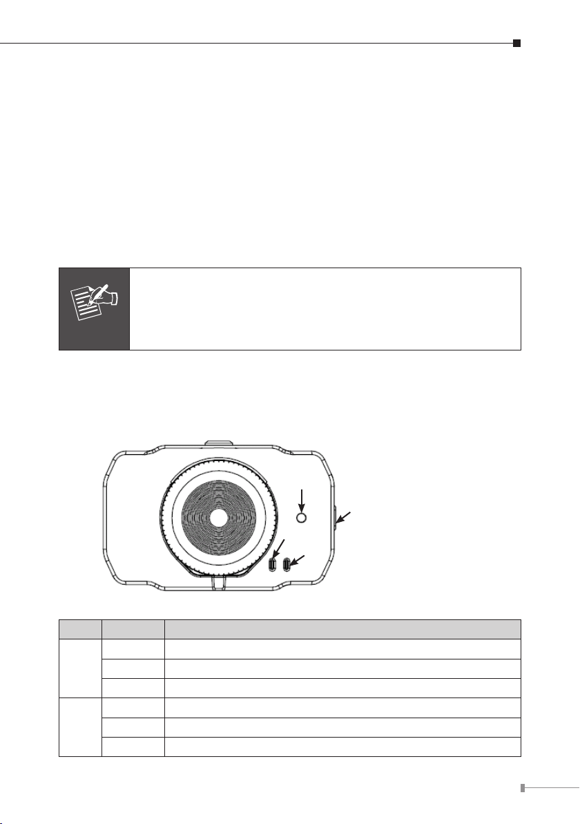
3.2.1 Front Panel
Microphone
DC-drive type
Auto Iris Lens Connector
PWR
LAN
LED Status LED Description
Off No power.
PWR
LAN
On Power on.
Blinking The Power LED will blink during start up (15 ~ 20 sec).
Off LAN connection is not detected.
On LAN connection is detected.
Blinking Data is being transmitted or received via the LAN connection.
7
Page 8
8
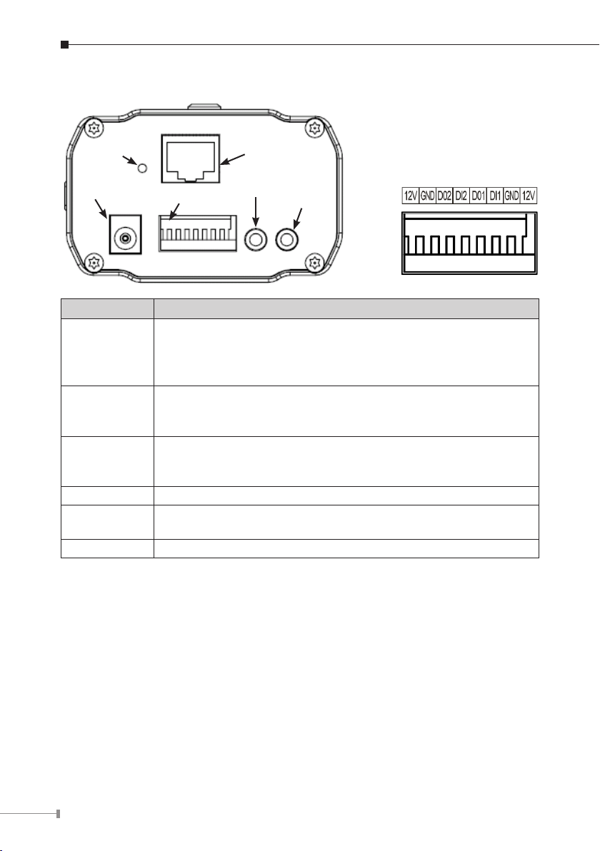
3.2.2 Rear Panel
LAN (PoE)
AUDIO IN
AUDIO OUT
I/O Info
PWR
Reset
DI / DO
PORT PORT Description
Reset to manufacturer default valued and reboot.
Reset
LAN (PoE)
PWR
DI / DO The terminal block includes 2 input ports and 2 output ports.
AUDIO IN
AUDIO OUT An external speaker can be plugged in.
When pressed and held over 10 seconds, the settings of IP
Camera will be set to the default values.
Upon completion, the PWE LED will blink three times.
Connect your Camera to a 10/100Base-TX hub or switch. This
interface compliant with IEEE802.3af standard PoE PD (Powered
Device). Either mid-span & end-span PSE can be used.
Connect to the supplied power adapter 12V DC, 1A. When this
device is obtaining power from PoE already, you don’t have to
attach the power adapter to ICA-750.
An external microphone can be plugged in. That will disable the
built-in microphone on the front panel.
3.3 Physical Installation
1. Connect an Ethernet cable
Connect one end of an Ethernet cable to the LAN port located on the IP camera’s
rear panel and connect the other end to the network device (hub or switch).
2. Attach the external power supply
Attach the provided power adapter to the IP camera’s connector labeled “PWR”
on the rear panel.
3. Check the LEDs
a. The Power LED will turn on briey, and then start blinking during startup.
After startup is completed, the Power LED will remain ON.
b. The LAN LED will be ON.
Page 9

Chapter 4. Setup Wizard Installation and operation
Note
Note
This chapter shows how to quick set up your IP surveillance product. The IP
surveillance product is with the default settings. However to help you nd the
networked camera quickly the windows utility-IP Wizard can search the cameras in
the network that shall help you to congure some basic setting before you started
advanced management and monitoring.
In the installation steps below, this guide use ICA-151 as the
example. However, the steps for ICA-750 are similar.
I Initial setup should be performed by using the supplied Windows-based Setup
Wizard as follows:
1. Insert the bundled Product CD into CD-ROM drive to launch the autorun
program.
2. After the web page displayed, click the
to start the conguration process.
If the CD’s menu does not appear, click “Start” on the task bar
and select “Run” to type “X:\Utility\SetupWizard\SetupWizard.
exe”, assume X is your CD-Rom drive.
“Setup Wizard” hyperlink on the menu
3. The welcome screen appears. Click on
wizard.
“Setup Camera” button to start the
9
Page 10

10
4. After clicking the setup camera button, it will auto search for the IP Cameras on
your network. Click on to continue.
5. The next screen below will list the IP Camera on your network. Select it from
the list on the left side, the current settings table will be displayed on the right
side. Click on to continue.
Page 11

6. The administrator login window will pop up. If the Administrator Name and
Administrator Password have been set, you will be prompted to enter them. If
using the default values, please enter “admin” for both the name and the password. Click on “OK” to continue.
7. On the following Camera Settings screen, you can ll and congure the Device
Name, Description, Time Zone, Local Date and time here. Click on to
continue.
11
Page 12

12
8. You can choose “Fixed IP Address” or “Dynamic IP Address” here. Click on
Note
to continue.
1. Fixed IP Address is recommended, and can always be used.
2. Dynamic IP Address can only be used if your LAN has a DCHP
Server.
9. If you chose to use Fixed IP Address, the following TCP/IP Settings screen will
be displayed. You can congure the IP Address, Subnet Mask, Default Gateway,
Primary and secondary DNS. Click on to continue.
Page 13
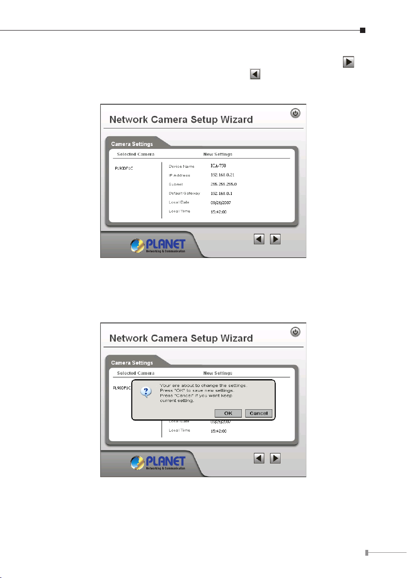
10. The next screen below will display all details of the IP Camera. Click on to
continue if those settings are correct, or click on back to modify any incorrect values.
11. In this conrmation window below, click on “OK” to conrm that you want
to save the new settings. If you want to cancel your changes, please click on
“Cancel”.
13
Page 14
14
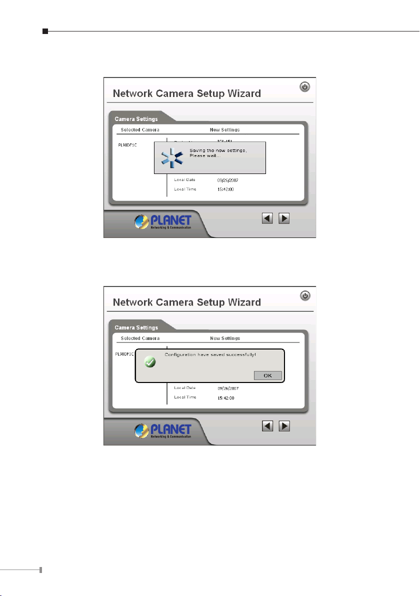
12. After conrming, the wizard will start to save the new settings as below screen.
13. When the saving process is completed, the prompt window will be displayed as
below screen. Click on “OK” to nish.
Page 15

14. The setup wizard now is completed. Click on “Exit” to close the setup wizard.
After modications, you may now connect the IP camera with new conguration.
15
Page 16

16
Chapter 5. Cam Viewer Plus Installation
Note
Note
The Cam Viewer Plus Pro 30 days trial version installation steps are
similar. Below is the installation of Cam Viewer Plus.
Insert the bundled CD disk into the CD-ROM drive to launch the autorun program.
Once completed, a welcome menu screen will appear. Click the “Cam Viewer Plus”
hyperlink, the below InstallShield Wizard dialog box will appear.
If the welcome screen does not appear, click “Start” at the taskbar.
Then, select “Run” and type “D:\Utility\Cam Viewer Plus\setup.exe”,
assume “D” is your CD-ROM drive.
Simply place the setup disc into your optical drive and wait for seconds, you will
see welcome web page, please click the Cam Viewer Plus to start the installation.
Select the language once the “Choose Setup Language” Windows pop-up, and then
click “Next” to continue the installation.
Page 17

The “Welcome” window will then pop-up, click on “Next” to continue.
You may choose where to install the program. Click on “Change” button to browse
your computer. Once you have specied the directory, click on “Next” to continue.
17
Page 18

18
You are now ready to install the program. Click on “Install” to begin the installation
process.
You will now see the installation progress. Please wait a few minutes to complete
the installation.
Page 19

Click on “Finish” to exit the InstallShield wizard.
You will now be prompted to create an administrator account. This account allows
full control of Cam Viewer Plus Pro. Enter a password for this administrator account
in the “Password” eld and re-enter it in “Password Conrm” eld.
19
Page 20

20
You will then be prompted to login by the administrator user name and password.
Enter “administrator” in the “User Name” eld. Enter the password you just created
in the “Password” eld.
You have successfully entered Cam Viewer Plus.
Page 21

Appendix A: Feature Listing for Cam Viewer Plus
Specication Description Cam Viewer Plus Pro Cam Viewer Plus
Live view
channel
E-Map
Remote
Server
Counting
Function
Compression
format
Open by
Event
Smart
Search
Intelligent
Guard
SMS Alarm Send a SMS to mobile phone. V N/A
Preset Go
Max. channels monitored
simultaneously
Showing camera's location
and map background
Provide remote server,
support remote live view
Provide counting function V N/A
H.264/MPEG4/MJPEG V V
Opens recorded video les by
event type
Event options:
- General Motion Detection
- Focal Loss Detection
- Missing Object Detection
- Foreign Object Detection
- Obstruction Detection
- Camera Tampering Detection
Searches archives by event on
specic area(s) on video
- Genera Motion Detection
- Missing Object Detection
- Foreign Object Detection
- Focal Loss Detection
- Obstruction Detection
- Camera Tampering Detection
Options:
- General Motion
- Focal Loss
- Missing Object
- Foreign Object
- Obstruction
- Camera Tampering
- Camera Signal Loss
Control PZ camera to a
specify location.
Up to 64 channels Up to 64 channels
V
V N/A
All
All
All
V N/A
N/A
General Motion
Detection /
Camera Signal
Lost
General Motion
Detection /
Camera Signal
Lost
General Motion
Detection /
Camera Signal
Lost
21
Page 22

22
Appendix B: Suggest Hardware / System Requirement
The Minimum system requirement
CPU
RAM 1 GB
Video RAM 128MB
Display Chip
Display Resolution 1024X768 24bits
Operating System
DirectX 9.0c
Required space for installation 100MB
Recommended HD free space 160 GB
Network Ethernet 100Base-TX
Recommended for 16 Channels on CIF resolution
CPU Intel® Core™2 Duo E7400
RAM 2 GB
Video RAM 256 MB
Display Chip
Recommended HD free space 160GB or above
Network Ethernet 100Base-TX or above
Intel® Pentium 4 3.0GHz with Hyperthreading
nVIDIA GeForce 8500GT
ATI Radeon HD 4350
Windows2000 SP4 / Windows XP Pro SP2 /
Windows 2003 /Vista
nVIDIA GeForce 8600GT
ATI Radeon HD 4670
Recommended for 64 Channels on CIF resolution
CPU Intel® Core™2 Quad Q8200
RAM 4 GB
Video RAM 1 GB
Display Chip
Recommended HD free space 500GB or above
Network Ethernet Gigabit LAN or above
nVIDIA GeForce 9500GT
ATI Radeon HD 4850
Page 23

Ordering Information for Cam Viewer Plus Pro
Model Description
CVPP-4 4-Channel Cam Viewer Plus Pro
CVPP-9 9-Channel Cam Viewer Plus Pro
CVPP-16 16-Channel Cam Viewer Plus Pro
CVPP-25 25-Channel Cam Viewer Plus Pro
CVPP-36 36-Channel Cam Viewer Plus Pro
CVPP-49 49-Channel Cam Viewer Plus Pro
CVPP-64 64-Channel Cam Viewer Plus Pro
Further Conguration
If you want to congure more detail settings of ICA-151 and ICA-750, please refer
to the user manual in the CD disk.
23
Page 24

This page is intentionally left blank
 Loading...