

Page 1

Table of Contents
Requirements 1
Physical Installation
ICA-110 2
W 3
ICA-110
ICA-100PE
ICA-100C
Configuration 4
Preparation 4
Connecting to the Internet Camera
Home Page
System
Camera Uility IPView Pro operation
Launch IPView Pro
Search Camera
Add Camera
View Camera
Quick reference in CD-ROM guide 17
3
4
5
5
9
14
14
15
16
1
Page 2

This page is intentionally left blank
Page 3

Requirements
Note:
Model ICA-110/ICA-100C ICA-110W ICA-100PE
Network Environment
LAN 10/ 100M Ethernet 10/ 100M Ethernet
Monitoring System Recommended to Access Internet Camera
System Hardware • CPU: Intel Celeron 1.1GHz or above (Intel Pentium 4 is preferred)
Web Browser • Internet Explorer 5.0 or above (ActiveX & JAVA Mode – Image View for Win
System Requirement for IPView Pro Application
Support OS Win 98 / SE/ Me / 2000 / XP
System Hardware • CPU: Intel Celeron 1.1GHz or above (Intel Pentium 4 is preferred)
A faster CPU and dedicated computer / notebook can support more
Internet cameras and more image frames.
10/ 100M Ethernet
IEEE 802.11g Wireless
LAN
• Memory Size: 128 MB or above
• VGA card resolution: 800x600 or above
dows OS and JAVA Mode – Image View for other OS)
• Netscape 6.0 or above (JAVA Mode – Image View)
• Memory Size: 512 MB or above.
• VGA card resolution: 1024x768 or above
Power over Ethernet IEEE
802.3af
Physical Installation
ICA-110
1. Connect an Ethernet cable
Connect one end of an Ethernet cable to the LAN port located on the ICA-110 rear panel
and attach the other end to the network device (hub or switch).
2. Attach the external power supply
Connect the provided power adapter to the ICA-110's connector labeled “5VDC” on rear
panel.
3. Check the LEDs
The PWR and ACT LEDs should be on.
1
Page 4
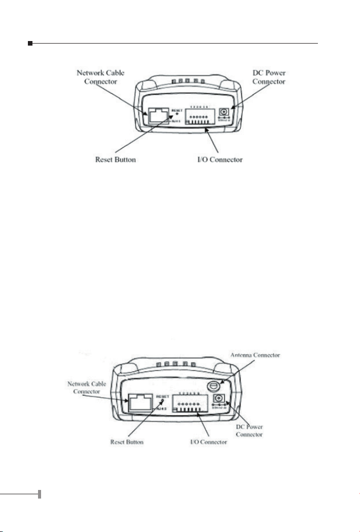
Physical Installation of ICA-110
ICA-110W
1. Attach Wireless Antenna
Screw the external antenna provided into the antenna connector located on ICA-110W's
rear panel.
2. Connect an Ethernet cable
Connect one end of an Ethernet cable to the LAN port located on the ICA-110W's rear
panel and attach the other end to the network device (hub or switch).
3.Attach the external power supply
Connect the provided power adapter to the ICA-110W's connector labeled “5VDC” on
rear panel.
5. Check the LEDs
The PWR and ACT LEDs should be on.
Physical Installation of ICA-110W
2
Page 5
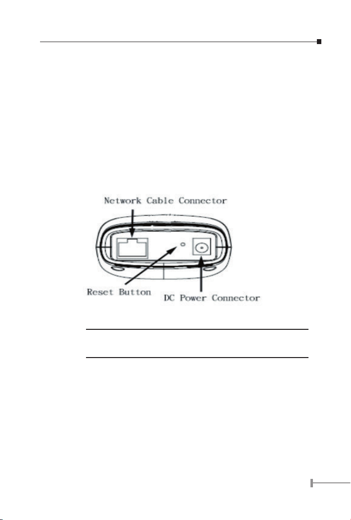
ICA-100PE
1. Connect an Ethernet cable
Connect one end of an Ethernet cable to the LAN port located on the ICA-100PE rear panel
and attach the other end to the network device (hub or switch).
2. Power over Ethernet IEEE 802.3 af
Simply connect the Ethernet cable, no power adapter needed.
3. Attach the external power supply
Connect the provided power adapter to the ICA-100PE's connector labeled “5VDC” on
rear panel.
4. Check the LEDs
The PWR and ACT LEDs should be on.
Physical Installation of ICA-100PE
Please choose either PoE or power adapter as the power supply for the
Note:
ICA-100PE. Do not connect both the PoE port, and the power adapter at
the same time, the unit might be damaged permanently.
ICA-100C
1. Connect an Ethernet cable
Connect one end of an Ethernet cable to the LAN port located on the ICA-100C rear panel
and attach the other end to the network device (hub or switch).
2. Attach the external power supply
Connect the provided power adapter to the ICA-100C's connector labeled “5VDC” on rear
panel.
3
Page 6
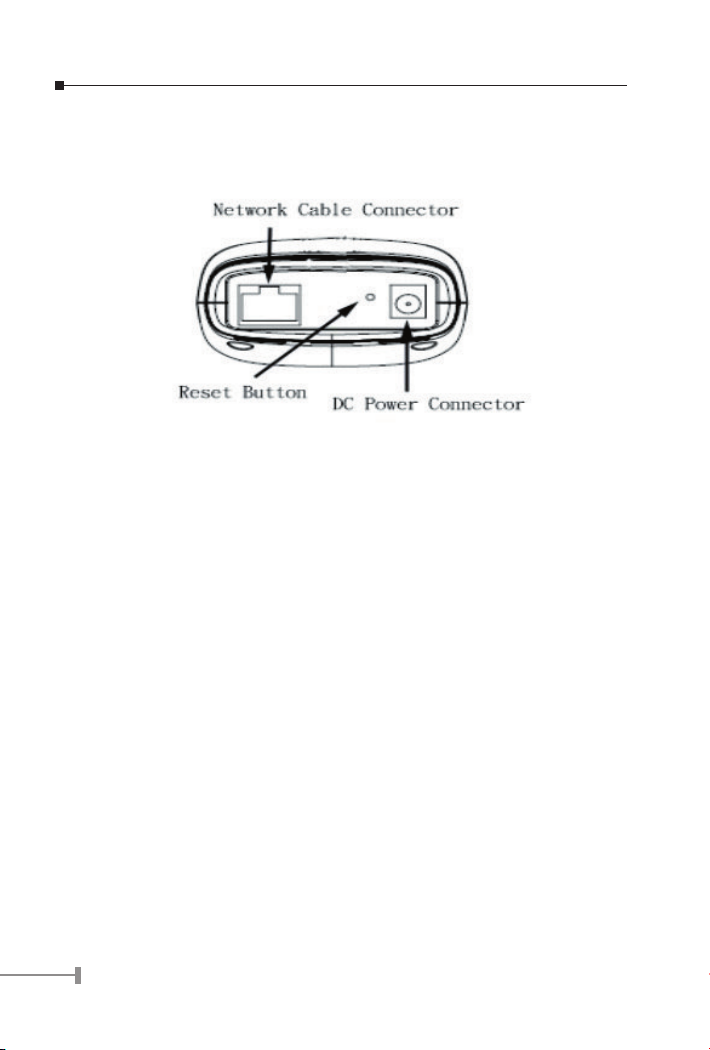
3. Check the LEDs
The PWR and ACT LEDs should be on.
Physical Installation of ICA-100C-V2
Configuration
The Internet Camera contains an HTTP server. This enables you to connect and configure
it using your Web Browser.
Preparation
Before attempting to connect the Internet Camera, please ensure that:
• The Internet Camera must be installed and powered ON.
• If the Internet Camera’s default IP Address (192.168.0.20) is already used by
another device, the other device must be turned OFF until the Internet Camera
is allocated a new IP Ad-dress during configuration.
• Your PC can establish a physical connection to the Internet Camera. The PC
and the Internet Camera must be directly connected (using the LAN port on
the Internet Camera) or on the same LAN segment. That is, the PC must be
configured to an IP address and subnet mask in 192.168.0.x segment. For
example: IP: 192.168.0.2, subnet mask: 255.255.255.0.
Connecting to the Internet Camera
To establish a connection from your PC to the Internet Camera:
1. Installing the Internet Camera in your LAN.
4
Page 7

2. Start WEB browser on one of the PCs in the same LAN segment.
3. In the Address box, enter “http://” and the IP Address of the Internet Cam-
era, as in this example, which uses the Internet Camera’s default IP Address:
http://192.168.0.20
If you have difficulties on entering the web interface by the default IP
address, press Internet Camera’s reset button continuously for three
Note:
seconds or till power LED begins to light up. Then the camera will reset
to factory default. No password and username are required in default
setting. It is strongly suggested that change the password and username
for security purpose.
Home Page
After you connect to the Internet Camera via web browser, the Home Page will appear.
System
Select “System Administration” to configure Internet Camera. There are many settings
to configure the Internet Camera in the system menu bar. Please select “Network” related
page to setup Internet Camera network environment.
5
Page 8

ICA-100C-V2 configuration
6
Page 9
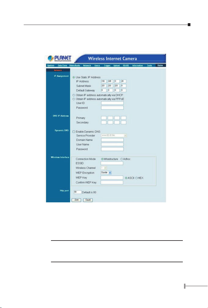
ICA-110W configuration
IP Assignment:
There are some options to select from the IP Assignment.
Access to Internet Camera is done through assigning a proper IP
Note:
address. Please make sure to use a vacant IP address when you assign
the IP address for Internet Camera. This will prevent errors from occurring if the IP address is overlapped.
7
Page 10

Manually Assign / Static IP Address
Directly enter the IP address according to local network environment.
The default settings are as follows:
• Default IP – 192.168.0.20
• Subnet Mask – 255.255.255.0
• Default Gateway – 0.0.0.0
Assign Automatically Using
If your network is using DHCP server you can click on “DHCP”. Under this setting
Internet Camera will automatically assign an IP address from DHCP server. Each
time Internet Camera starts up make sure the DHCP server is setup well to be able
to assign a static IP to your Internet Camera. If your application requires direct
connection from an ADSL modem then you need to have an ISP
Click on “PPPoE” option and enter the User ID and Password into the respective fields.
Internet Camera will get an IP address from the ISP each time Internet Camera
boots.
PPPoE account.
DNS IP Address:
DNS (Domain Name System) server is an Internet service that translates domain names
into IP addresses. Enter at least one DNS IP address.
Dynamic DNS:
Before using this feature, you have to register an account, password, and DDNS domain
name from a DDNS service provider. Then select one DDNS provider from the pull-down
menu and fill in information in corresponding fields.
Wireless Interface: (ICA-110W only)
Connection Mode:
Use the Connection Mode to determine the type of wireless communication for ICA110W. There are two choices of
Infrastructure mode, and Adhoc mode.
ESSID (Extended Service Set ID):
This field is used to setup which wireless network to be connected for ICA-110W
communication. The ESSID is a unique identifier shared among all clients in a wireless
network environment. The default Network Name is blank space (NULL String), this
default setting will let ICA-110W connect to ANY access point under the infrastructure
network mode. To connect ICA-110W to a specific access point on the network make
sure to set the ESSID of ICA-110W to correspond with the access point’s ESSID
for communication. Type any string up to 32 characters long (spaces, symbols, and
punctuation are not allowed) in the Network Name box.
To connect ICA-110W to an Ad-hoc wireless workgroup, make sure to set the same
wireless channel and ESSID to match with the PC/Notebook’s setting for direct
wireless communication under the Ad-hoc wireless workgroup.
8
Page 11

Wireless Channel:
The pull down menu provides the wireless channel for commu-nication. A “channel”
is a range of frequencies to be used in communication between ICA-110W and Access
Point in infra-structure mode or ICA-110W and PC/Notebook in Ad-hoc mode. Select
the appropriate channel from the list provided depending on the regulatory region
that the unit is sold.
WEP Encryption:
The default setting for the Encryption Key is Disable. Therefore, to secure the wireless
transmission, be sure to enable this option.
WEP Key:
While enabling WEP Encryption, please select the encryption format ASCII or HEX
and enter the relevant data. Please refer to User’s Manual on bundled CD for detailed
information about configuring WEP parameters.
Confirm WEP Key:
Enter the same WEP Key to confirm.
Save/Cancel:
After making sure all settings are correct, click on the “
Internet Camera. You can alternatively click on the “
the values last saved to or retrieved from Internet Camera.
Save” icon to store the settings for
Cancel” icon to restore all settings to
Camera Utility IPView Pro operation
As a standalone, network camera, you can use the web browser to view the images;
however, the software IPView Pro in the CD-ROM enables the system administrator up to
16 cameras centralized management
Installation
STEP 1
Insert the CD-ROM into the CD-ROM drive to initiate the autorun program. Once
completed a menu screen will appear as follows:
9
Page 12

STEP 2
To install the IPView Pro Application click on the “IPView Pro” hyperlink to activate the
installation procedure for the application program.
If the above screen is not shown, you can start the installation as follows.
1. Click on Start Menu/ Run.
2. Enter D:\UTILITY\IPViewPro\ipviewprosetup.exe in the appeared box, where
D is the letter of your CD-ROM drive.
3. Click on “OK” button.
10
Page 13

STEP 3
The Welcome screen will appear. Click on the "Next" button to proceed with the
installation.
STEP 4
The License Agreement prompt will appear as below. Read the details carefully and click
on the "Yes" icon to continue with the installation procedure.
11
Page 14

STEP 5
A prompt will appear and in the Destination Location dialog box, you may click on "Next"
to accept the recommended destination location or click on "
location. After specifying the desired destination location, click on "
further.
Browse" to select another
Next" to proceed
STEP 6
The Select Program Folder prompt will appear providing information where the IPView Pro
application will be located, click on "
previous screens.
Next" to continue. Click on "Back" can return to the
12
Page 15

STEP 7
Please wait until one of the following two dialog boxes to appear. If the system has to
restart, select "Yes, I want to restart my computer now" and click the
complete the installation procedure.
Finish button to
Otherwise, you may simply click the
procedure.
Finish button to complete the installation
13
Page 16
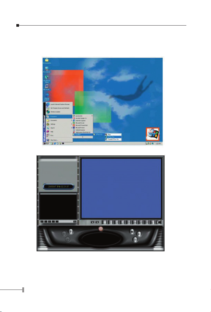
Launch IPView Pro
After successfully installing the IPView Pro, the application program is automatically
installed to \Program Files\IPView Pro. Click on Start > Programs > PLANET> IPView
Pro > IPView Pro to launch the program.
Once IPView Pro is launched, the following main screen will appear.
Search Camera
Press the configuration button below the camera viewing screen on the right site. Then
the following dialog will appear, press search button to search for the available Internet
Cameras.
14
Page 17
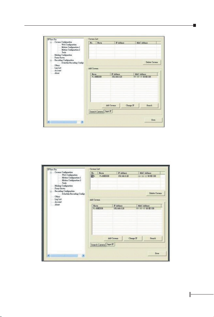
Add Camera
Once the available cameras are displayed in the Add Camera column, then select a
camera and press Add Camera button. After adding the camera, the camera name will be
displayed in the Camera List column as following picture:
15
Page 18

View Camera
Press save button to save the configuration. Then press the configuration button again to
close the configuration window in order to go back the main screen. Now user can view
the video image as following picture:
16
Page 19

Quick reference in CD-ROM guide
This guide is used to help you startup your Internet camera. It is also recommended to
check the CD-ROM manual for more detail information, and product features.
17
Page 20

This page is intentionally left blank
 Loading...