

Page 1

Page 2

Copyright
Copyright 2012 by PLANET Technology Corp. All rights reserved. No part of this publication may be
reproduced, transmitted, transcribed, stored in a retrieval system, or translated into any language or computer
language, in any form or by any means, electronic, mechanical, magnetic, optical, chemical, manual or
otherwise, without the prior written permission of PLANET.
PLANET makes no representations or warranties, either expressed or implied, with respect to the contents
hereof and specifically disclaims any warranties, merchantability or fitness for any particular purpose. Any
software described in this manual is sold or licensed "as is". Should the programs prove defective following their
purchase, the buyer (and not this company, its distributor, or its dealer) assumes the entire cost of all necessary
servicing, repair, and any incidental or consequential damages resulting from any defect in the software. Further,
this company reserves the right to revise this publication and to make changes from time to time in the contents
hereof without obligation to notify any person of such revision or changes.
All brand and product names mentioned in this manual are trademarks and/or registered trademarks of their
respective holders.
Federal Communication Commission Interference Statement
This equipment has been tested and found to comply with the limits for a Class A digital device,
pursuant to Part 15 of FCC Rules. These limits are designed to provide reasonable protection
against harmful interference in a residential installation. This equipment generates, uses, and can
radiate radio frequency energy and, if not installed and used in accordance with the instructions, may cause
harmful interference to radio communications. However, there is no guarantee that interference will not occur in
a particular installation. If this equipment does cause harmful interference to radio or television reception, which
can be determined by turning the equipment off and on, the user is encouraged to try to correct the interference
by one or more of the following measures:
Reori
1.
2. Increase the separation between the equipment and receiver.
3. Connect the equipment into an outlet on a circuit different from that to which the receiver is connected.
4. Consult the dealer or an experienced radio technician for help.
ent or relocate the receiving antenna.
FCC Caution:
To assure continued compliance, (example-use only shielded interface cables when connecting to computer or
peripheral devices) any changes or modifications not expressly approved by the party responsible for
compliance could void the user’s authority to operate the equipment.
This device complies with Part 15 of the FCC Rules. Operation is subject to the Following two conditions:
(1) This device may not cause harmful interference
(2) This Device must accept any interference received, including interference that may cause undesired
operation.
Any changes or modifications not expressly approved by the party responsible for compliance could void the
user’s authority to operate the equipment.
I
Page 3

Federal Communication Commission (FCC) Radiation Exposure Statement
This equipment complies with FCC radiation exposure set forth for an uncontrolled environment. In order to
avoid the possibility of exceeding the FCC radio frequency exposure limits, human proximity to the antenna
shall not be less than 20 cm (8 inches) during normal operation.
CE mark Warning
This is a class B device, in a domestic environment; this product may cause radio interference, in which case
the user may be required to take adequate measures.
Energy Saving Note of the Device
This power required device does not support Stand by mode operation.
For energy saving, please remove the DC-plug or push the hardware Power Switch to OFF position to
disconnect
the device from the power circuit.
Without remove the DC-plug or switch off the device, the device will still consuming power from the power circuit.
In the view of Saving the Energy and reduce the unnecessary power consuming, it is strongly suggested to
switch off or remove the DC-plug for the device if this device is not intended to be active.
R&TTE Compliance Statement
This equipment complies with all the requirements of DIRECTIVE 1999/5/CE OF THE EUROPEAN
PARLIAMENT AND THE COUNCIL OF 9 March 1999 on radio equipment and telecommunication terminal
Equipment and the mutual recognition of their conformity (R&TTE).
The R&TTE Directive repeals and replaces in the directive 98/13/EEC (Telecommunications Terminal
Equipment and Satellite Earth Station Equipment) As of April 8, 2000.
Safety
This equipment is designed with the utmost care for the safety of those who install and use it. However, special
attention must be paid to the dangers of electric shock and static electricity when working with electrical
equipment. All guidelines of this and of the computer manufacture must therefore be allowed at all times to
ensure the safe use of the equipment.
National Restrictions
This device is intended for home and office use in all EU countries (and other countries following the EU directive
1999/5/EC) without any limitation except for the countries mentioned below:
Country Restriction Reason/remark
Bulgaria None
General authorization required for outdoor use and
public service
Outdoor use limited to 10
France
Italy None
Luxembourg None
mW e.i.r.p. within the band
2454-2483.5 MHz
Military Radiolocation use. Refarming of the 2.4 GHz
band has been ongoing in recent years to allow current
relaxed regulation. Full implementation planned 2012
If used outside of own premises, general authorization is
required
General authorization required for network and service
supply(not for spectrum)
II
Page 4

ay Implemented
Norw
Russian Federation None Only for indoor applications
This subsection does not apply for the geographical area
within a radius of 20 km from the centre of Ny-Ålesund
WEEE Regulation
To avoid the potential effects on the environment and human health as a result of the presence of
hazardous substances in electrical and electronic equipment, end users of electrical and electronic
equipment should understand the meaning of the crossed-out wheeled bin symbol. Do not dispose of
WEEE as unsorted municipal waste and have to collect such WEEE separately.
Revision
User’s Manual for PLANET Industrial 802.11n PoE Wireless Access Point
Model: IAP-2000PE / IAP-2000PS / IAP-2001PE
Rev: 1.2 (February, 2012)
Part No. EM-IAP200x_v1.2 (2081-E50230-001)
III
Page 5

CONTENTS
Chapter 1. INTRODUCTION ..................................................................................... 6
1.1. Package Contents ....................................................................................................... 6
1.2. Product Features.........................................................................................................6
1.3. Product Specification .................................................................................................7
Chapter 2. INSTALLATION ....................................................................................... 9
2.1. Hardware Description .................................................................................................9
2.1.1. Physical Dimension........................................................................................................... 9
2.1.2. Front Panel .....................................................................................................................10
2.1.3. LED Indicators ................................................................................................................ 11
2.1.4. Upper Panel ....................................................................................................................12
2.2. Hardware Installation................................................................................................ 12
2.2.1. Installation Steps............................................................................................................. 12
2.2.2. DIN-Rail Mounting........................................................................................................... 13
2.2.3. Wall Mount Plate Mounting .............................................................................................16
2.3. Wiring the Power Input ............................................................................................. 16
2.4. Cabling .......................................................................................................................18
2.4.1. Installing the SFP Transceiver (IAP-2001PE Only)......................................................... 18
2.4.2. Removing the Module ..................................................................................................... 19
Chapter 3. USER MANAGEMENT INTERFACE .................................................... 21
3.1. Overview ....................................................................................................................21
3.2. Requirements.............................................................................................................21
3.3. Management Method.................................................................................................21
3.3.1. Web Management...........................................................................................................21
3.3.2. PLANET Smart Discovery Utility .....................................................................................23
Chapter 4. WEB CONFIGURATION ....................................................................... 26
4.1. Main Menu.................................................................................................................. 26
4.2. Web Panel ..................................................................................................................27
4.3. System........................................................................................................................ 28
4.3.1. Operation Mode ..............................................................................................................28
4.3.2. Management ...................................................................................................................29
4.3.3. SNMP Configuration .......................................................................................................30
4.3.4. Status..............................................................................................................................32
4.4. Network Settings ....................................................................................................... 34
4.4.1. LAN................................................................................................................................. 34
4.4.2. DHCP Clients.................................................................................................................. 37
4.4.3. IPv6................................................................................................................................. 37
4.5. Wireless Settings ......................................................................................................38
4.5.1. Basic ...............................................................................................................................38
4.5.2. Advanced ........................................................................................................................41
4.5.3. Security ........................................................................................................................... 44
4.5.4. WPS................................................................................................................................54
4.5.5. WDS................................................................................................................................58
4.5.6. Station List ......................................................................................................................63
4.6. Layer 2 Functions...................................................................................................... 64
4.6.1. Port Status ......................................................................................................................64
IV V
Page 6

4.6.2. Port Setting ..................................................................................................................... 65
4.6.3. VLAN Setting ..................................................................................................................65
4.6.4. MAC Address Table......................................................................................................... 67
4.7. System Tools .............................................................................................................67
4.7.1. PoE Configuration........................................................................................................... 68
4.7.2. IPv6 Ping......................................................................................................................... 70
4.7.3. Upload Firmware............................................................................................................. 71
4.7.4. Settings Management ..................................................................................................... 71
4.7.5. Reboot ............................................................................................................................72
4.7.6. Statistics.......................................................................................................................... 73
4.8. System Log ................................................................................................................74
Chapter 5. PoE (Power over Ethernet) Overview................................................. 75
5.1. What is PoE? .............................................................................................................75
5.2. PoE Provision Process ............................................................................................. 77
Appendix A. Networking Connection ................................................................... 79
A.1. DATA OUT PoE Switch RJ-45 Port Pin Assignments (Port-1 to Port-4) .............. 79
A.2. 10/100Mbps, 10/100Base-TX....................................................................................79
Page 7

User’s Manual of IAP-200x Series
Chapter 1. INTRODUCTION
The PLANET 802.11n Industrial Access Point Series – IAP-2000PS / IAP-2000PE / IAP-2001PE are industrial
grade multiple 10/100Mbps ports wireless Access Point. The descriptions of these models are listed as below:
Model Description
IAP-2000PS
IAP-2000PE
IAP-2001PE
802.11n 4 x 10/100Base-TX Ports with 4-port POE (PSE, Power Sourcing Equipment)
802.11n 4 x 10/100Base-TX Ports with 1-port POE (PD, Powered Device)
802.11n 4 x 10/100Base-TX Ports with 1-port POE (PD, Powered Device) + 1 x
100FX (SFP Slot)
1.1. Package Contents
Thank you for choosing the PLANET IAP-200x Industrial AP. Please check if the following items are contained in
the package:
PLANET IAP-200x Industrial AP x 1
5 dBi Antenna x 2
Quick Installation Guide x 1
CD-ROM (User’s Manual included) x 1
DIN Rail Kit x 1
Wall Mount Kit x 1
If any of these are missing or damaged, please contact your dealer immediately, if possible, retain the carton
including the original packing material, and use them against to repack the product in case there is a need to
return it to us for repair.
1.2. Product Features
IAP-2000PS
4 x 10/100Base-TX Ports with 4-Port PoE (PSE, Power Sourcing Equipment)
IAP-2000PE
4 x 10/100Base-TX Ports with 1-Port PoE (PD, Powered Device)
IAP-2001PE
4 x 10/100Base-TX Ports with 1-Port PoE (PD, Powered Device) + 1 x 100FX (SFP Slot)
IPv4 / IPv6 Web Management
Complies with IEEE 802.11n Wireless LAN Speed Up to 300Mbps
2 x 5dBi Detachable Omni-directional Antenna
Supports 64/128-bit WEP, WPA/WPA2, and WPA-PSK/WPA2-PSK, 802.1x
Supports WISP Mode, IEEE 802.1Q VLAN
-6-
Page 8
User’s Manual of IAP-200x Series
-10 to 60 Degree C Operating Temperature
Redundant Power Design
IP-30 Aluminum case protection / DIN Rail and Wall-mount Design
1.3. Product Specification
Model IAP-2000PS IAP-2000PE IAP-2001PE
Hardware Specification
10/100Base-TX Ports
IEEE 802.3af PoE Ports 4 x PSE 1 x PD 1 x PD
PoE Power Supply Type End-Span N/A
100Base-FX Interface N/A 1 x SFP slot
4 x 10/100Base-TX Auto-Negotiation
Auto MDI / MDI-X
Antenna
Enclosure
LED Indicators
Button
Dimensions (D x W x H) 135mm x 87.8mm x 56mm
Weight 871g
Power Requirement DC 24V / 48V AC 24V DC 12~48V / AC 24V
Installation DIN Rail Kit and Wall Mount Ear
2 x Detachable RP-SMA Connector
2 x 5dBi SMA Omni-directional antenna included in the package
IP-30 Metal Case
P1, P2, PWR, FAL,
WPS, WLAN, SEC,
LAN1~4, PoE
WPS Button
Reset Button
P1, P2, PWR, FAL,
WPS, WLAN, SEC,
LAN1~4, PoE-In-Use
P1, P2, PWR, FAL,
FX, WPS, WLAN, SEC,
LAN1~4, PoE
Wireless Interface Specification
Standard Compliance with IEEE 802.11b/g/n
Frequency Band 2.4 to 2.4835GHz (Industrial Scientific Medical Band)
DSS with DBPSK, DQPSK, QPSK and CCK
Modulation Type
Wireless Data Rate
OFDM with BPSK, QPSK, 16-QAM and 64-QAM
IEEE 802.11b: 1/2/5.5/11Mbps
IEEE 802.11g: 6/9/12/18/24/36/48/54Mbps
IEEE 802.11n: 14/29/43/58/87/116/130/144Mps in 20MHz
30/60/90/120/180/240/270/300Mbps in 40MHz
Opt. Channel
RF Output Power
Receiver Sensitivity
America / FCC: 2.414~2.462GHz (11 Channels)
Europe / ETSI: 2.412~2.472GHz (13 Channels)
Japan / TELEC: 2.412~2.484GHz (14 Channels)
802.11b: 18 dBm
802.11g: 15 dBm
802.11n: 15dBm
802.11b CCK 1.0Mbps: -94dbm
11b CCK 11.0Mbps: -91dbm
802.11g OFDM 6Mbps: -92dbm
11g OFDM 54Mbps: -76dbm
802.11n 20MHz MCS7: -72dbm
-7-
Page 9

11n 40MHz MCS7: -70dbm
Wireless Management Features
User’s Manual of IAP-200x Series
Wireless Mode
Channel Width
Data Encryption Security
Management Web-based Configuration
Wireless Isolation Yes
Access Point
20MHz / 40MHz
64 bit / 128 bit WEP
WPA / WPA2
WPA-PSK / WPA2 / WPA2-PSK
802.1x Network Access Control
Protocol
Bridge and WISP mode
WDS and WPS
Static Routing and RIPv1/2
DMZ and Virtual Server
802.1D
802.1Q VLAN
Protocol / Feature
Management Web-based configuration
QoS
SNTP
WMM
DHCP Server / Client
IGMP Proxy and DNS Proxy
UPnP and DDNS
SNMP
Standards Conformance
IEEE 802.11b/g and 802.11n Wireless LAN
IEEE 802.3 Ethernet
Standards Compliance
IEEE 802.3u Fast Ethernet
IEEE 802.3x Full-Duplex Flow Control
IEEE 802.3af Power over Ethernet
IEEE 802.1Q VLAN
Environment Specification
Temperature / Humidity
Emission FCC, CE
Stability Testing
Operating: -10~60 Degree C, 5%~ 90% (non-condensing),
Storage: -20~70 Degree C, 0~95% (non-condensing)
IEC60068-2-32 (Free Fall)
IEC60068-2-27 (Shock)
IEC60068-2-6 (Vibration)
-8-
Page 10
User’s Manual of IAP-200x Series
Chapter 2. INSTALLATION
2.1. Hardware Description
2.1.1. Physical Dimension
IAP-200x series Industrial Access Point dimension (D x W x H) : 135mm x 87.8mm x 56mm
Figure 2-1 IAP-200xPx diagram
-9-
Page 11
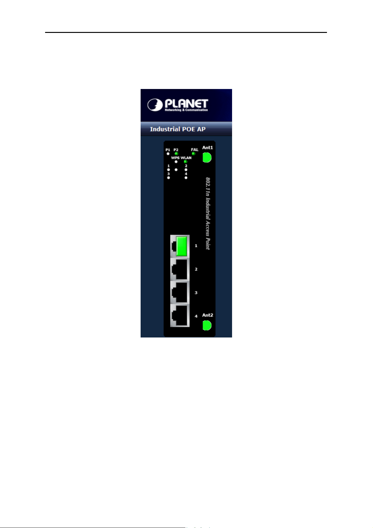
2.1.2. Front Panel
Figure 2-2 & 2-3 & 2-4 show the front panels of Industrial Access Points
User’s Manual of IAP-200x Series
Figure 2-2 IAP-2000PS Figure 2-3 IAP-2000PE Figure 2-4 IAP-2001PE
■ Reset Button
In the bottom of the front panel, the reset button is designed for reset the Industrial Access Point to the factory
default settings.
Figure 2-5 Reset button of IAP-200x series
-10-
Page 12
The following is the summary table of Reset button functions:
Reset Button Pressed and Released Description
User’s Manual of IAP-200x Series
About 1~3 second
Over 5 seconds
2.1.3. LED Indicators
System
LED Color Function
P1 Green
P2 Green
PWR Green
Reboot the Industrial AP
Reset the Industrial AP to the Factory Default
configuration. The Industrial AP will then reboot and
load the default settings as below:
。 Default Username/Password: admin / admin
。 Default IP address: 192.168.1.1
Subnet mask: 255.255.255.0
It indicates the power 1 has power.
It indicates the power 2 has power.
It indicates the machine is power on.
FAL Green
It indicates either the power 1 or power 2 has no
power.
Wireless LAN
LED Color Function
WPS Orange
WLAN Green
SEC Orange
It indicates WPS is enabled.
It indicates the wireless LAN is enabled.
It indicates the wireless security encryption is
enabled.
10/100Base-TX Ports / 100Base-FX Port
LED Color Function
1 ~ 4 Green
FX Green
It indicates which RJ-45 port is link up.
It indicates the Fiber port is link up. (IAP-2001PE)
PoE Orange
PoE
Orange
In-Use
It indicates the device is power supplied by PoE.
It indicates which RJ-45 port is providing 48V DC
in-line power.
-11-
Page 13
2.1.4. Upper Panel
User’s Manual of IAP-200x Series
Figure 2-6 IAP-2000PS Upper Panel
Figure 2-7 IAP-2000PE / IAP-2001PE Upper Panel
2.2. Hardware Installation
This section describes how to install your Industrial access point and make connection to it. Please read the
following topics and perform the procedures in the order being presented. To install your wireless access point on
a desktop or shelf, simply complete the following steps.
2.2.1. Installation Steps
1. Unpack the package of Industrial Access Point
2. Check if the DIN-Rail is screwed on the Industrial Access Point or not. If the DIN-Rail is not screwed on
-12-
Page 14
User’s Manual of IAP-200x Series
the Industrial access point, please refer to DIN-Rail Mounting section for DIN-Rail installation. If users want
to wall mount the Industrial access point, please refer to Wall Mount Plate Mounting section for wall mount
plate installation.
3. To hang the Industrial access point on the DIN-Rail track or wall.
4. Power on the Industrial access point. Please refer to the Wiring the Power Inputs section for knowing the
information about how to wire the power. The power LED on the Industrial access point will light up. Please
refer to the LED Indicators section for indication of LED lights.
5. Prepare the twisted-pair, straight through Category 5 cable for Ethernet connection.
6. Insert one side of RJ-45 cable (category 5) into the Industrial access point Ethernet port (RJ-45 port)
and another side of RJ-45 cable (category 5) to the network device’s Ethernet port (RJ-45 port), ex: Switch
PC or Server. The UTP port (RJ-45) LED on the Industrial access point will light up when the cable is
connected with the network device. Please refer to the LED Indicators section for LED light indication.
Make sure that the connected network devices support Auto MDI/MDI-X. If it does
not support, use the crossover category-5 cable.
7. When all connections are set and LED lights all show in normal, the installation is complete.
2.2.2. DIN-Rail Mounting
This section describes how to install the Industrial Access Point. There are two methods to install the Industrial
PoE Switch. DIN-Rail Mounting and Wall Mount Plate Mounting. Please read the following topics and perform the
procedures in the order being presented.
In the installation steps below, we use PLANET IGS-801(8 Port Industrial
Gigabit Switch) as the example. However, the steps for PLANET Industrial
Access Point are similar.
-13-
Page 15
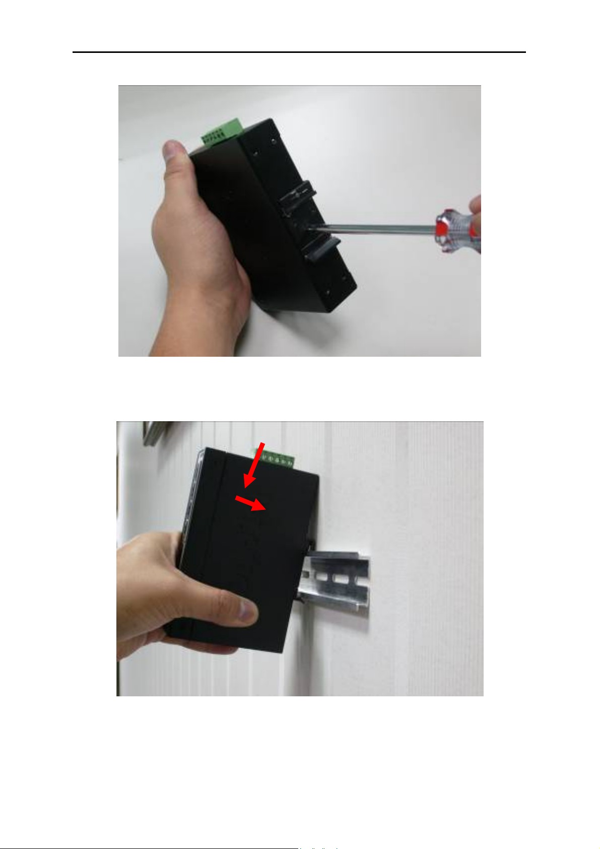
Step 1: Screw the DIN-Rail on the Industrial Access Point.
User’s Manual of IAP-200x Series
Figure 2-8
Step 2: Lightly press the button of DIN-Rail into the track.
Fi
gure 2-9
-14-
Page 16
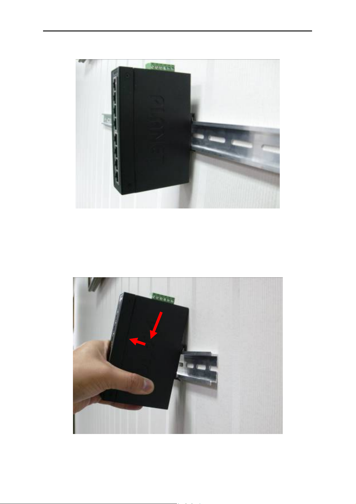
Step 3: Check the DIN-Rail is tightly on the track.
User’s Manual of IAP-200x Series
Fi
gure 2-10
Please refer to the following procedures to remove the Industrial Access Point from the track.
Step 5: Lightly press the button of DIN-Rail for remove it from the track.
Figure 2
-15-
-11
Page 17
User’s Manual of IAP-200x Series
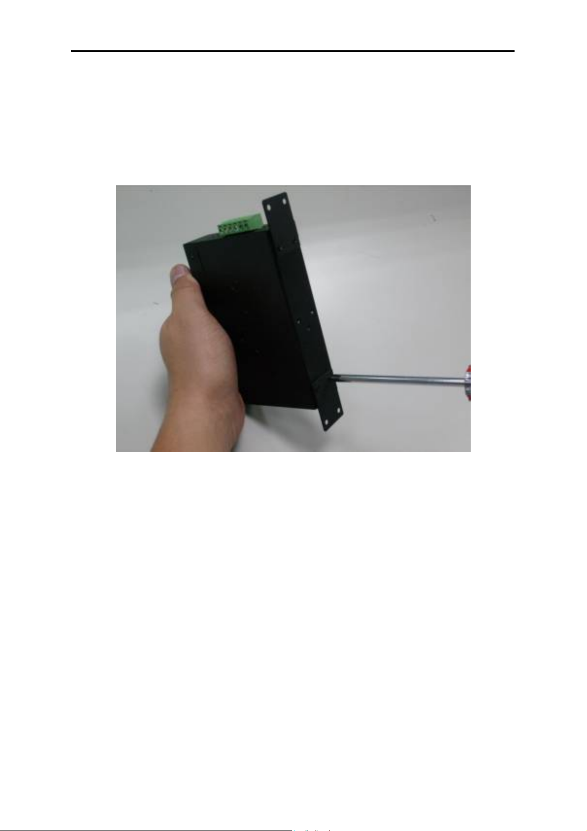
2.2.3. Wall Mount Plate Mounting
To install the Industrial Access Point on the wall, please follow the instructions below.
Step 1: Remove the DIN-Rail from the Industrial Access Point. Use the screwdriver to loose the screws and
remove the DIN-Rail.
Step 2: Place the wall mount plate on the rear panel of the Industrial Access Point.
Figure 2-12
Step 3: Use the screwdriver to screw the wall mount plate on the Industrial Access Point.
Step 4: Use the hook holes at the corners of the wall mount plate to hang the Industrial Access Point.
Step 5: To remove the wall mount plate, reverse the steps above.
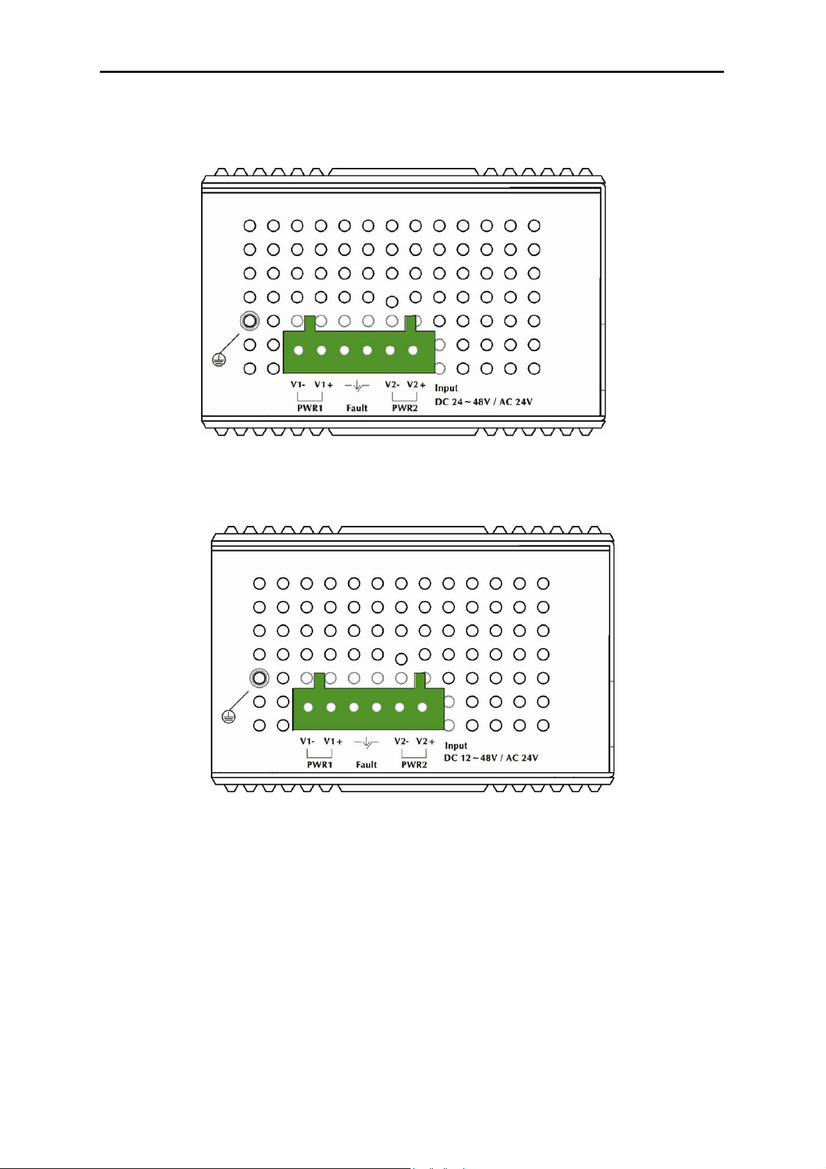
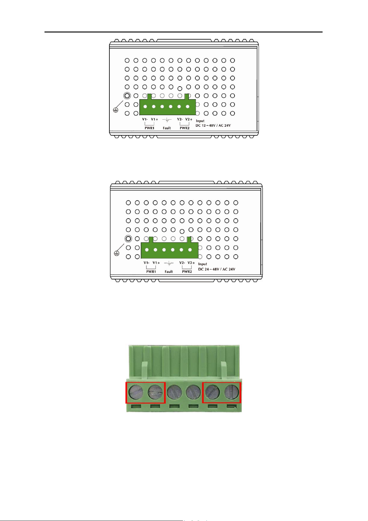
2.3. Wiring the Power Input
The 6-contact terminal block connector on the top panel of the Industrial access point is used for two DC
redundant powers input. Please follow the steps below to insert the power wire.
1. Insert positive / negative DC power wires into the contacts 1 and 2 for POWER 1, or 5 and 6 for
POWER 2.
-16-
Page 18
User’s Manual of IAP-200x Series
V1- V1 + V2 - V2 +
Figure 2-13 The Top Panel of IAP-2000PE / IAP-2001PE
V1- V1 + V2 - V2 +
Figure 2-14 The Top Panel of IAP-2000PS
2. Tighten the wire-clamp screws for preventing the wires from loosing.
1 2 3 4 5 6
Power 1 Fault Power 2
- + - +
Figure 2-15 The Terminal Block
-17-
Page 19

User’s Manual of IAP-200x Series
The wire gauge for the terminal block should be in the range between 12 ~ 24 AWG.
The Power input voltage of IAP-2000PE and IAP-2001PE is DC 12~48V / AC 24V.
The Power input voltage of IAP-2000PS is 24V or 48V DC only.
For PD devices, like IAP-2000PE / IAP-2001PE, the power 1, power 2, and PoE
power supplied can exist at the same time.
2.4. Cabling
100Base-TX and 100Base-FX
The 10/100Mbps RJ-45 ports come with Auto-Negotiation capability. Users only need to plug in working
network device into one of the 10/100Mbps RJ-45 ports. The IAP-2000PS / IAP-2000PE series will
automatically run in 10Mbps or 100Mbps after the negotiation with the connected device. The IAP-2001PE
has one 100Base-FX SFP interface (Optional Multi-mode / Single-mode 100Base-FX SFP module)
Cabling
Each 10/100Base-TX ports use RJ-45 sockets - for connection of unshielded twisted-pair cable (UTP).
Port Type Cable Type Connector
10Base-T Cat 3, 4, 5, 2-pair RJ-45
100Base-TX Cat.5, 5e, 6 UTP, 2-pair RJ-45
Any Ethernet devices like Hubs / PCs can connect to the Industrial Access Point by using straight-through wires.
The 10/100Mbps RJ-45 ports which support Auto MDI / MDI-X can be used on straight-through or crossover cable.
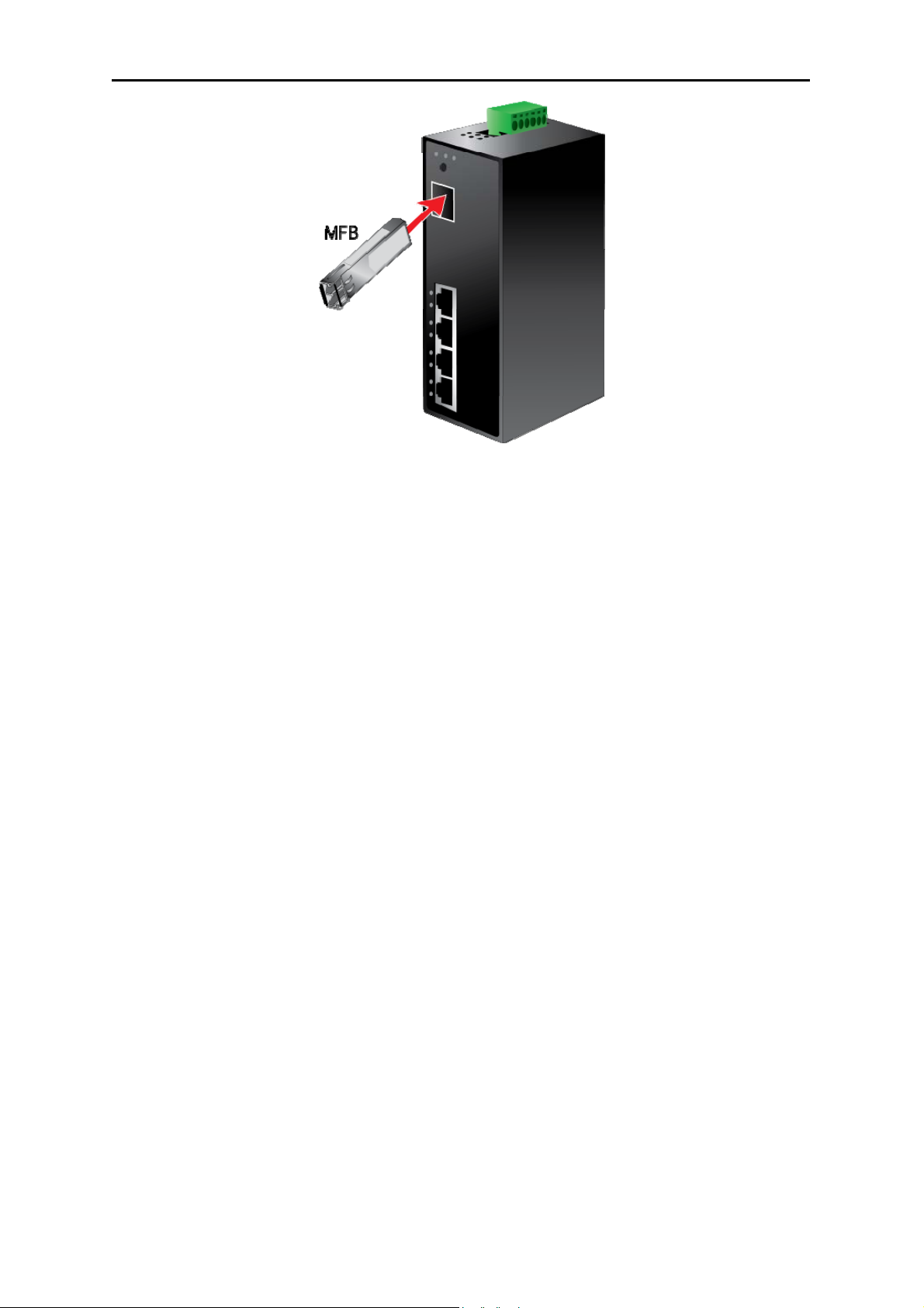
2.4.1. Installing the SFP Transceiver (IAP-2001PE Only)
This section describes how to insert a SFP transceiver into an SFP slot. The SFP transceiver is hot-pluggable and
hot-swappable. You can plug-in and out the transceiver to/from any SFP port without having to power down the
Industrial Access Point as the Figure 2-12 appears.
-18-
Page 20
User’s Manual of IAP-200x Series
Figure 2-16 Plug in the SFP transceiver
Before connect the other switches, workstation or Media Converter,
1. Make sure both side of the SFP transceiver are with the same media type or WDM pair, for example:
100Base-FX to 100Base-FX, 100Base-BX20-U to 100Base-BX20-D.
2. Check the fiber-optic cable type match the SFP transceiver model.
To connect to MFB-FX SFP transceiver, use the multi-mode fiber cable- with one side must be male
duplex LC connector type.
To connect to MFB-F20/F40/F60/FA20/FB20 SFP transceiver, use the single-mode fiber cable-with
one side must be male duplex LC connector type.
Connect the fiber cable
1. Attach the duplex LC connector on the network cable into the SFP transceiver.
2. Connect the other end of the cable to a device – switches with SFP installed, fiber NIC on a workstation or a
Media Converter.
3. Check the LNK/ACT LED of the SFP slot of the switch / converter. Ensure that the SFP transceiver is
operating correctly.
4. Check the Link mode of the SFP port if the link failed. Co works with some fiber-NICs or Media Converters,
set the Link mode to “100 Force” is needed.
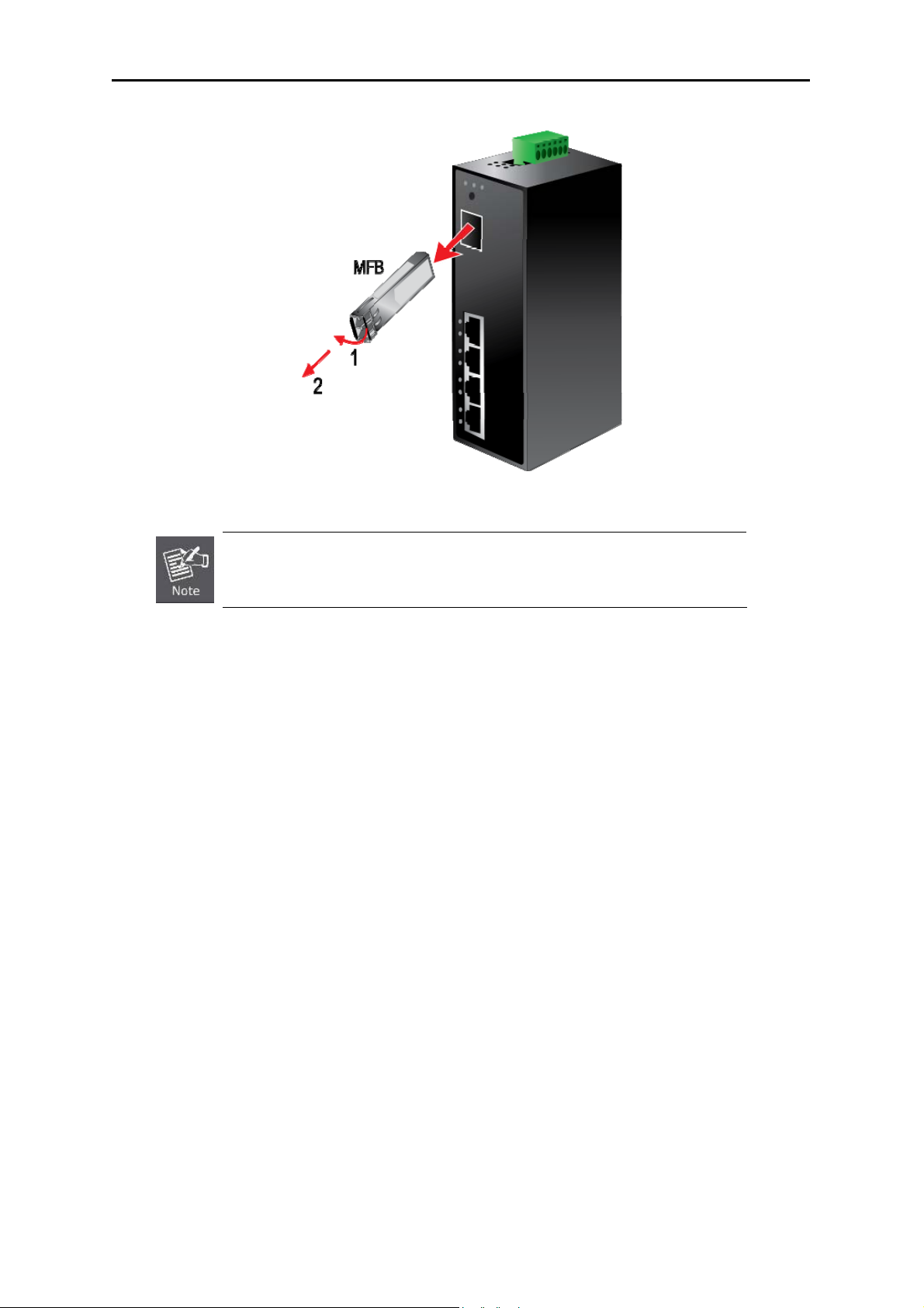
2.4.2. Removing the Module
1. Please make sure there is no network activity by console or check with the network administrator. You can
access the management interface of the Industrial Access Point to disable the port in advance.
2. Remove the Fiber Optic Cable gently.
3. Turn the handle of the MFB module to horizontal.
4. Pull out the module gently through the handle.
-19-
Page 21
User’s Manual of IAP-200x Series
Figure 2-17 Pull Out the SFP transceiver
Never pull out the module without pull the handle or the push bolts on the module.
Direct pull out the module with violent could damage the module and SFP module
slot of the device.
-20-
Page 22

User’s Manual of IAP-200x Series
Chapter 3. USER MANAGEMENT INTERFACE
3.1. Overview
The Industrial Access Point provides a user-friendly, Web interface. Via this interface, you can perform various
device configuration and management activities, including:
System
Power over Ethernet
Too ls
3.2. Requirements
Network cables. Please use standard network (UTP) cables with RJ-45 connectors.
Subscriber PC installed with Ethernet NIC (Network Card)
The operating system of subscriber PC that running Windows XP/2003, Vista, Windows 7, MAC OS X ,
Linux, Fedora, Ubuntu, and any other platform compatible with TCP/IP protocol.
It is recommended to use Internet Explore 7.0 or above to access the web UI of
Industrial Access Point.
3.3. Management Method
Users can manage the Industrial Access Point by Web UI via a network connection.
3.3.1. Web Management
The IAP-200x Series provide a bui
e
Access Point via a r
Chrome or Apple Safari.
mote host with web browser, such as Microsoft Internet Explorer, Mozilla Firefox, Google
lt-in web management interface. You can manage the Industrial Wireless
The following procedures show that how to startup the Web Management of the IAP-200x Series.
-21-
Page 23
User’s Manual of IAP-200x Series
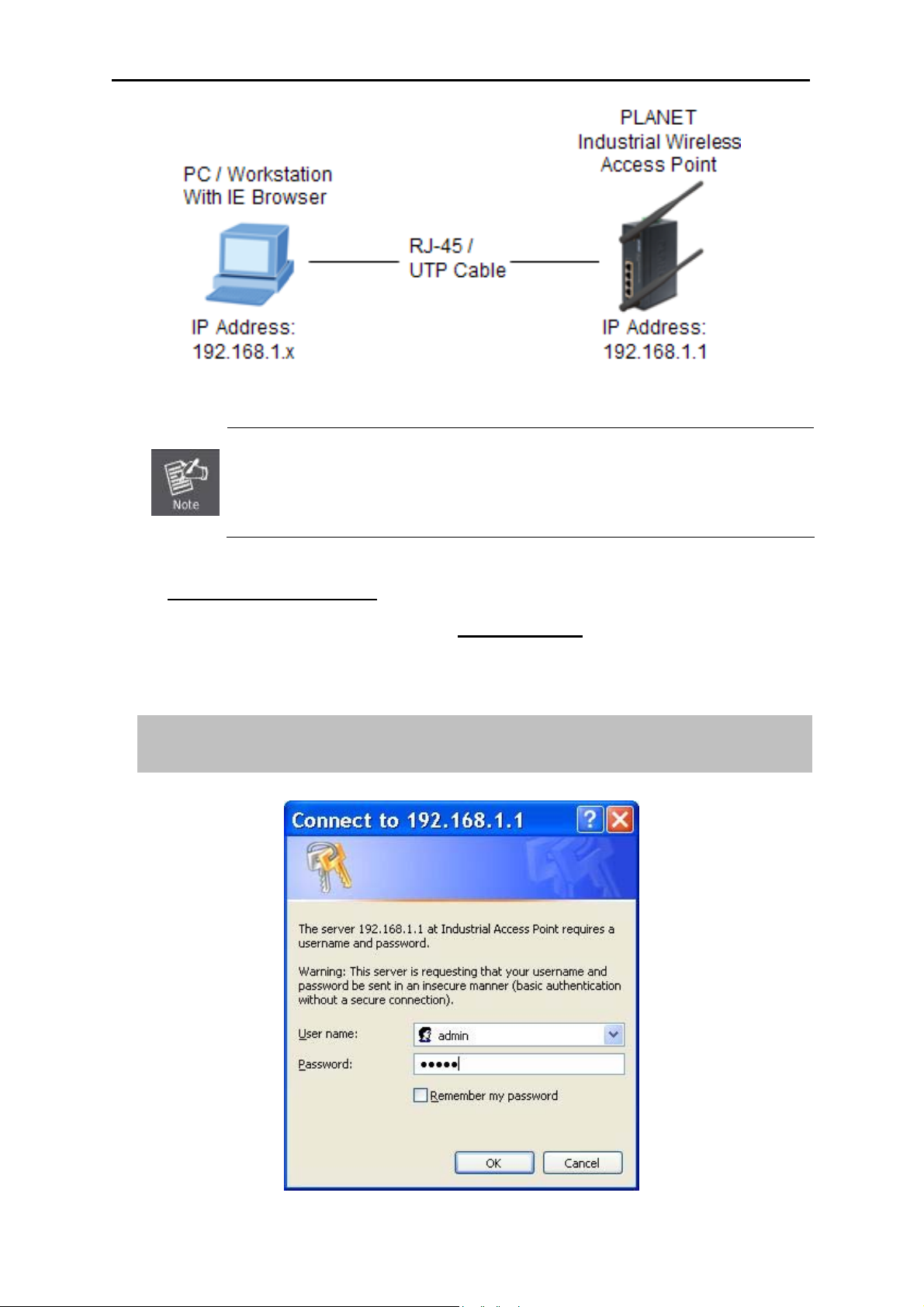
Figure 3-1 IP Management Diagram
The IAP-200x Series need to be configured through the Ethernet connection, so the
manager PC must be on the same IP subnet address. The default setting of the
DHCP server in the IAP-200x Series is disabled. If your PC obtains the IP address
from other devices, please manually configure the correct IP address as
192.168.1.xxx, xxx is from 2 to 254.
Login to the IAP-200x Series
1. Open the web browser, and enter IP address http://192.168.1.1
(the factory-default IP address if
you have not changed before) to access the management interface.
2. When the following window appears, please enter the user name and password.
Default User name: admin
Default Password: admin
Figure 3-2 Login Window
-22-
Page 24
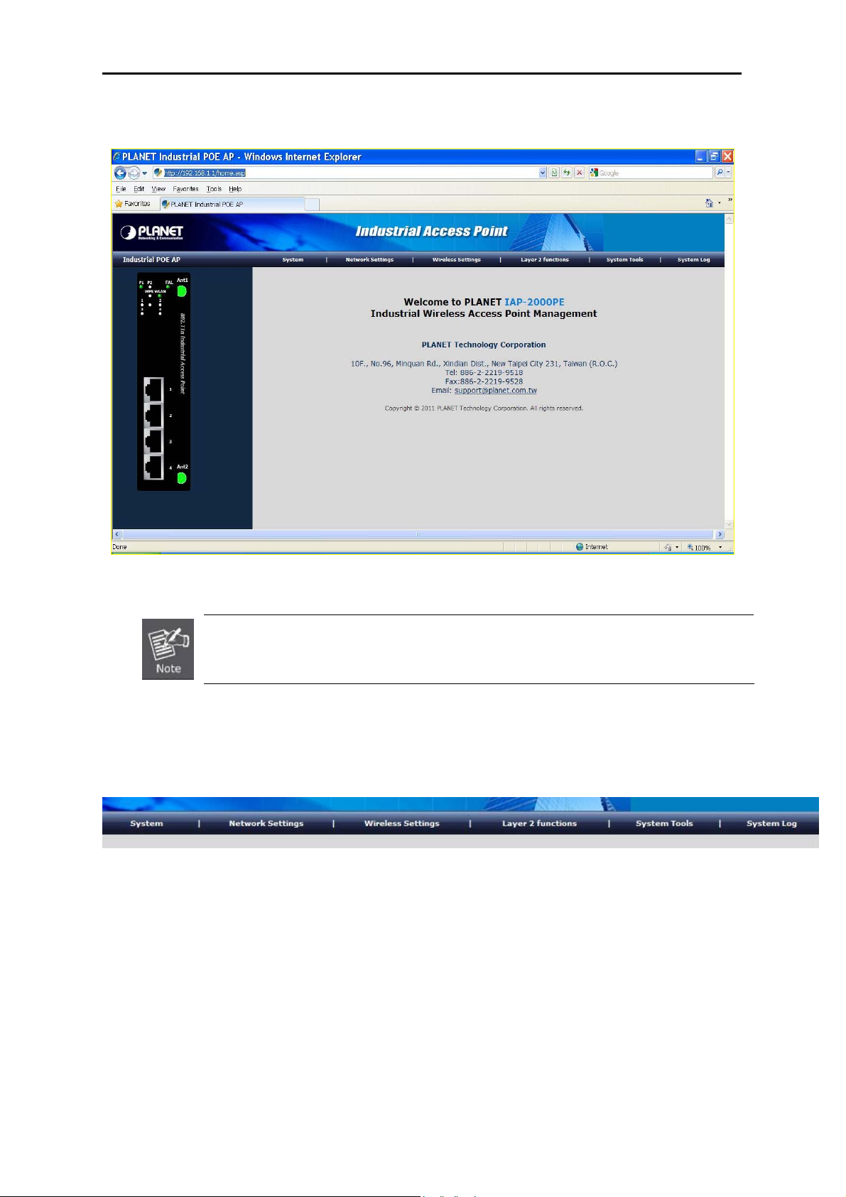
User’s Manual of IAP-200x Series
3. After entering the user name and password, you will see the main screen based on IAP-2000PE
as Figure 3-3 for example.
Figure 3-3 Main Screen of IAP-2000PE Web UI
1. For security reason, please change and remember the new password after first setup.
2. Only the command in lowercase letter is accepted under WEB interface.
Now, you can configure the IAP-200x Series via web management interface. If you need more detailed description
of any function, please refer to the following sections for further information.
Figure 3-4 The Function Label of the Web UI
3.3.2. PLANET Smart Discovery Utility
For easily list the PLANET Industrial Access Point in your Ethernet environment, the Planet Smart Discovery Utility
from user’s manual CD-ROM is an ideal solution. The following instructions will guide you to launch the Planet
Smart Discovery Utility:
1. Deposit the Planet Smart Discovery Utility in administrator PC.
2. Run this utility and the following screen will appear.
-23-
Page 25
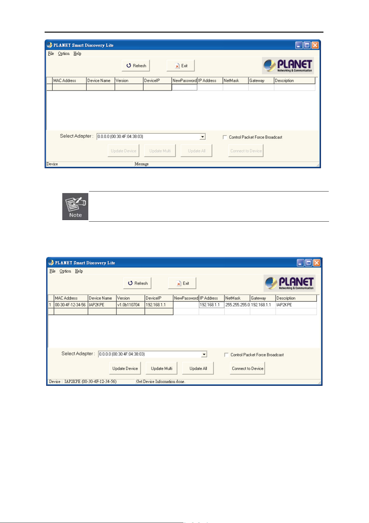
User’s Manual of IAP-200x Series
Figure 3-5 PLANET Smart Discovery Utility Snapshot
If there are two LAN cards or above in the same administrator PC, please choose the different
LAN card via the “Select Adapter” field.
3. Click “Refresh” button to renew the list of the PLANET industrial devices connected in the network. The
screen is shown as follow.
Figure 3-6 PLANET Smart Discovery Utility Screen
4. This utility shows all necessary information of the devices, such as MAC address, device name, firmware
version, device IP subnet address. Users can also assign new password, IP subnet address, and description
for the devices.
5. After the setup is completed, click “Update Device”, “Update Multi” or “Update All” button to take effect.
The meaning of the 3 buttons above are shown as below:
Update Device: update the current setting on one single device.
Update Multi: choose the multi-devices for updating the current setting.
-24-
Page 26

User’s Manual of IAP-200x Series
Update All: use current setting on every device in the list.
The same functions mentioned above can be found in “Option” tools bar as well.
6. Click the “Control Packet Force Broadcast” function, and it will assign new setting value to the switch
under different IP subnet address.
7. Click the “Connect to Device” button, and the Web login window as Figure 3-2 will appear.
8. Click “Exit” button to exit the Planet Smart Discovery Utility.
-25-
Page 27
User’s Manual of IAP-200x Series
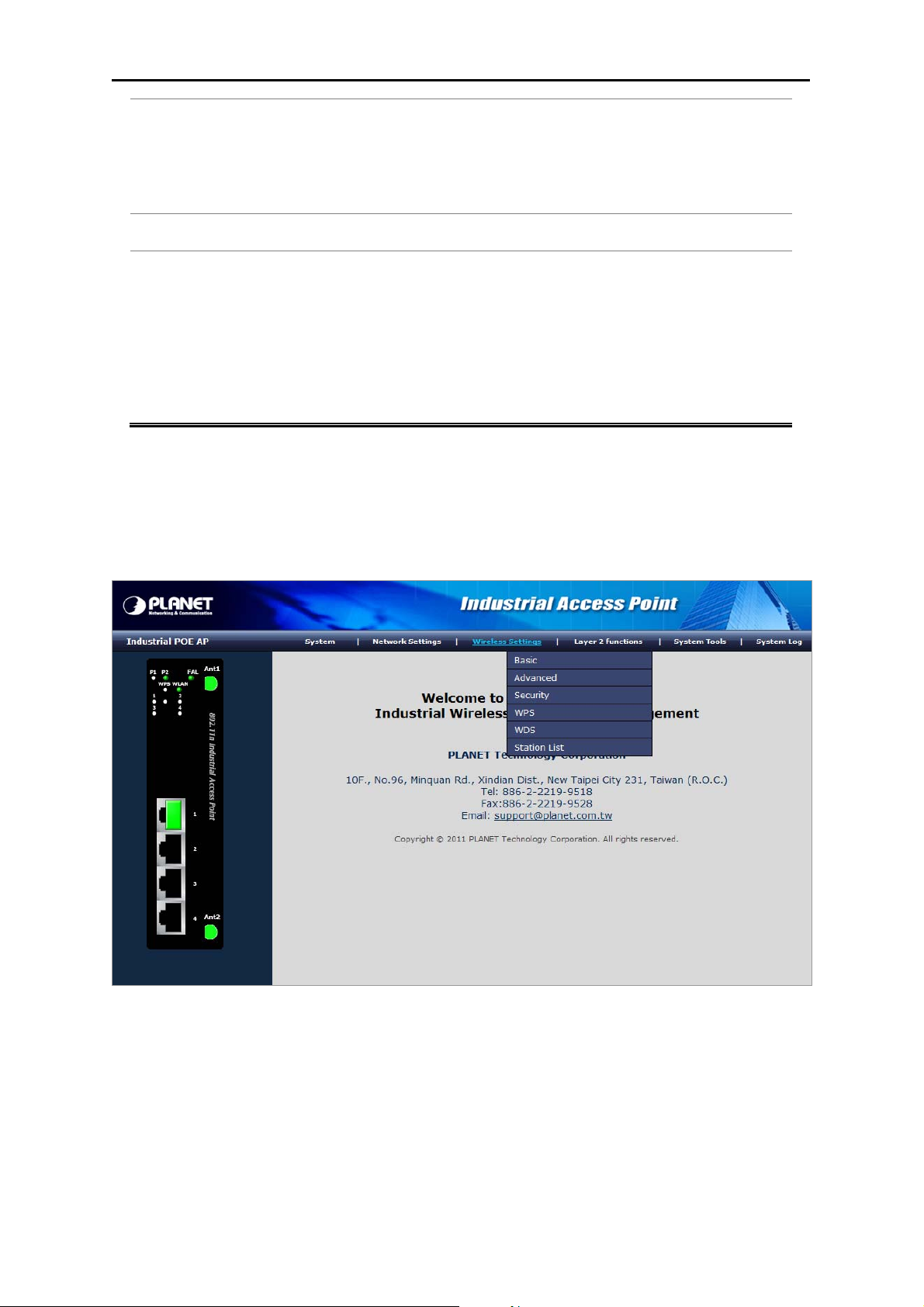
Chapter 4. WEB CONFIGURATION
The Industrial Access Point provides Web interface for configuration and make the Industrial Access Point operate
more effectively - Users can configure through the Web Browser and the network administrator can manage and
monitor the Industrial Access Point from the local LAN. This chapter indicates how to configure the Industrial
Access Point to enable its each function.
4.1. Main Menu
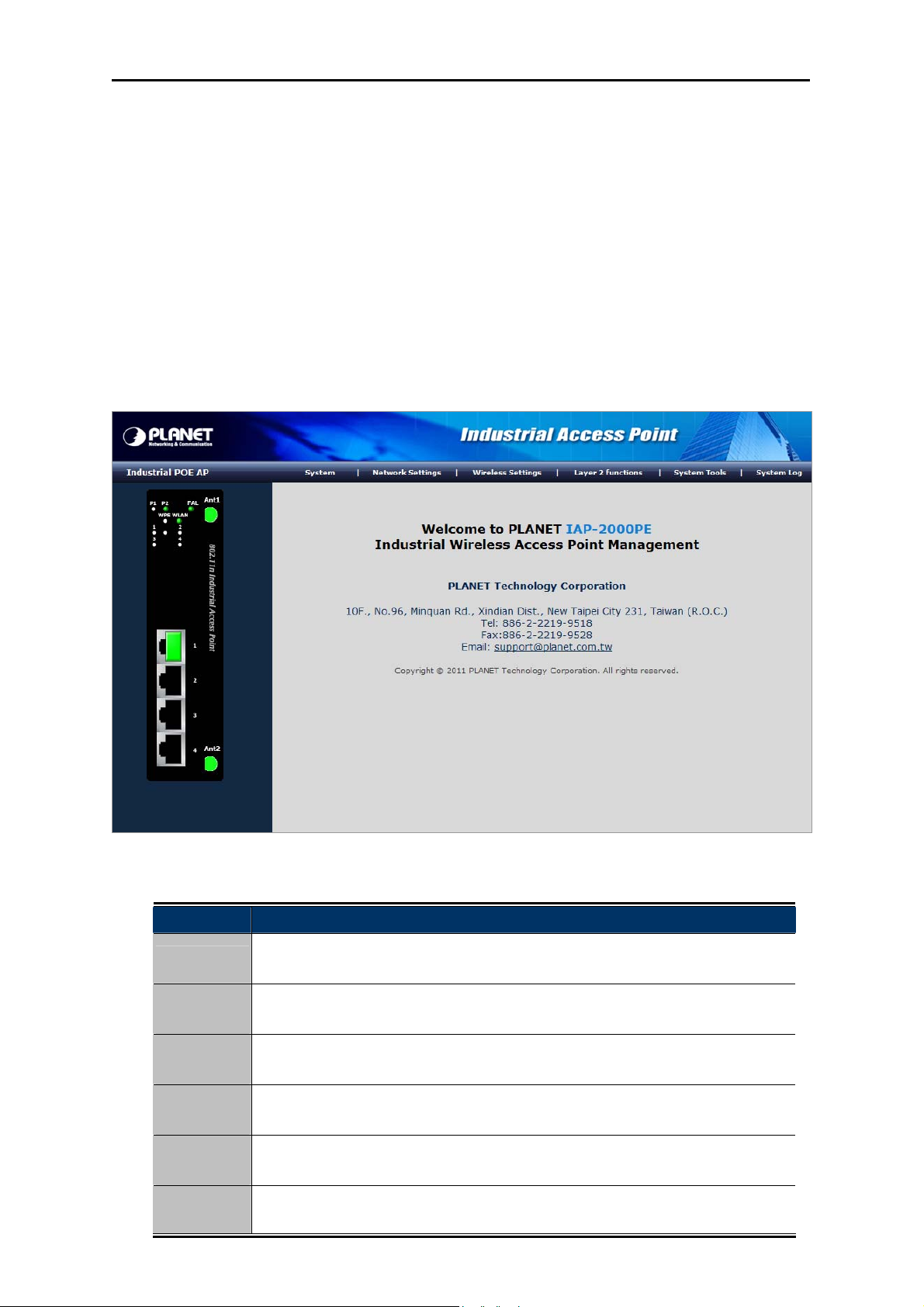
After a successful login, the main screen appears. The main screen displays the product name, the function menu,
and the main information in the center.
Figure 4-1 Main Menu Screen
Main Menu Description
System
Network
Settings
Wireless
Settings
Layer 2
Functions
System
Too ls
System Log This menu provides the system log of the AP. It will be explained in section 4.8.
This menu provides the system information and configuration of AP. It will be
explained in section 4.3.
This menu provides the configuration of LAN. It will be explained in section 4.4.
This menu provides the configuration of wireless function. It will be explained in
section 4.5.
This menu provides the port configuration. It will be explained in section 4.6.
This menu provides the system tools of the AP. It will be explained in section 4.7.
-26-
Page 28
User’s Manual of IAP-200x Series
4.2. Web Panel
On the left of the web management page, the active panel displays the link status of management port and PoE
ports.
Figure 4-2 Left Side of the Main Menu Screen (Light Indicators)
Please refer the section 2.1.3 to find the descriptions of each LED.
-27-
Page 29

4.3. System
The submenus of System option is shown below:
User’s Manual of IAP-200x Series
Figure 4-3
4.3.1. Operation Mode
Select the operation mode you want to use, and then click Apply button to make the changes take effect.
Figure 4-4
-28-
Page 30

User’s Manual of IAP-200x Series
Bridge:
The Bridge mode allows that all Ethernet and wireless interfaces are bridged into a single Bridge interface.
Wireless ISP:
The Wireless ISP mode allows that the wireless interface is treated as WAN port, and the Ethernet ports are
LAN ports.
4.3.2. Management
Users may configure administrator account and password, NTP settings, and dynamic DNS settings in
the page.
Figure 4-5 System Management Screenshot
Administrator Settings
Object Description
Account:
Enter the username of the administrator in the field.
Maximum length: 16 characters.
-29-
Page 31

Password:
Enter the password of the administrator in the field.
Maximum length: 16 characters.
NTP Settings
Object Description
User’s Manual of IAP-200x Series
Current Time:
Time Zone:
NTP Server:
NTP
Display the current date and time.
Click Sync with host, the current time is synchronized by your PC which is
connected to Router.
Select the proper time zone in the drop-down list.
Enter the IP address or domain name of NTP server.
Enter the time interval for synchronization.
Synchronization
(hours):
DDNS Settings
Object Description
Dynamic DNS
Provider:
Select the proper dynamic DNS provider in the drop-down list. After
selecting a dynamic DNS provider, you are allowed to set the
following parameters.
Account:
Enter the username of DDNS provider in the field.
Password:
DDNS:
Click Apply to make the configuration take effect. Click Cancel to cancel the new configuration.
Enter the password of DDNS provider in the field
Enter the domain name of your device.
4.3.3. SNMP Configuration
The Simple Network Management Protocol (SNMP) is an application layer protocol that facilitates the exchange
of management information between network devices. It is part of the Transmission Control Protocol/Internet
Protocol (TCP/IP) protocol suite. SNMP enables network administrators to manage network performance, find and
solve network problems, and plan for network growth.
Users can enable of disable the SNMP function, and configure the related settings in this page. The default SNMP
mode is disabled.
-30-
Page 32

User’s Manual of IAP-200x Series
The page includes the following fields:
SNMP Configuration
Object Description
Mode :
System Contact :
System Name :
Indicates the SNMP mode operation. Possible modes are:
Enabled: Enable SNMP mode operation.
Disabled: Disable SNMP mode operation.
The textual identification of the contact person for this managed node,
together with information on how to contact this person.
An administratively assigned name for this managed node. By convention,
this is the node's fully-qualified domain name. A domain name is a text
string drawn from the alphabet (A-Za-z), digits (0-9), minus sign (-). No
space characters are permitted as part of a name. The first character must
be an alpha character. And the first or last character must not be a minus
Figure 4-6
sign.
-31-
Page 33

The allowed string length is 0 to 255.
User’s Manual of IAP-200x Series
System Location :
Allowed IP to Access:
The physical location of this node (e.g., telephone closet, 3rd floor).
Indicates the host can access the AP from SNMP interface that the host IP
address matched the entry.
Read Community :
Here you can define and fill the Read community string.
Read only. Enables requests accompanied by this community string to
display MIB-object information.
Write Community :
Here you can define and fill the Write community string.
Write. Enables requests accompanied by this community string to display
MIB-object information and to set MIB objects.
Trap Configuration
Object Description
Mode :
Indicates the SNMP trap mode operation. Possible modes are:
Enabled: Enable SNMP trap mode operation.
Disabled: Disable SNMP trap mode operation.
Trap Community:
Trap Destination :
Enter the community string for the trap station.
Enter the IP address of the trap manager.
Click Apply to make the configuration take effect. Click Reset button to reset the whole configuration to default.
4.3.4. Status
Users can check the current status of the IAP-2000 in this page. The Status page provides information for the
current device information. This page helps a network administrator to identify the model name, firmware /
hardware version and MAC address. The screen in Figure 4-7 appears.
-32-
Page 34

User’s Manual of IAP-200x Series
The page includes the following fields:
Object Description
Firmware Version :
System Up Time:
Operation Mode:
MAC Address:
RF Mode :
SSID :
BSSID :
Channel :
Displays the Industrial AP’s firmware version.
The period of time the device has been operational.
Displays the current operation mode.
Displa
Displays the current wireless band.
Displays the current SSID.
Displays the MAC address of the wireless interface.
Displ
Figure 4-7
ys the unique hardware address assigned by manufacturer (default).
ays the current channel setting.
-33-
Page 35

4.4. Network Settings
The submenus of Network Settings option is shown below:
User’s Manual of IAP-200x Series
Figure 4-8
4.4.1. LAN
Users can configure the network settings and the parameters as you wish.
-34-
Page 36

User’s Manual of IAP-200x Series
The page includes the following fields:
LAN Interface Setup
Object Description
IP Address:
Subnet Mask:
Default Gateway:
Primary DNS Server:
Secondary DNS
Server:
MAC Address:
Enter the IP address of LAN port or reset it in dotted-decimal notation.
Factory default : 192.168.1.1
Enter the subnet mask of LAN port. The subnet mask is an address code
that determines the size of the network.
Normally use 255.255.255.0 as the subnet mask.
The default gateway that you want to use.
The primary DNS server address that you want to use.
The secondary DNS Server address that you want to use.
MAC addr
Figure 4-9
ess of LAN port (Read-only).
-35-
Page 37

User’s Manual of IAP-200x Series
DHCP T
ype:
802.1d Spanning
Tree:
LLTD:
IGMP Proxy:
UPNP:
Router
Advertisement:
DNS Proxy
:
DHCP Server Enable
You can select Server or Disable.
Disable: If you select Disable, the DHCP service of LAN side is
disabled.
Server: After selecting Server, the DHCP server is enabled on LAN
side. You can set the items as “DHCP Server Enable”.
Spanning Tree Protocol. You can select Enable or Disable.
Select enable or disable the Link Layer Topology Discover function from
pull-down menu.
Select enable or disable the IGMP proxy function from pull-down menu.
Universal Plug and Play (UPNP).You can select Enable or Disable.
You can select Enable or Disable.
Select enable or disable the DNS Proxy function from pull-down menu.
Object Description
Start IP Address:
The first IP address that DHCP server assigns. Client with DHCP function
set will be assigned an IP address from the range.
End IP Address:
Subnet Mask:
Primary DNS Server:
Secondary DNS
The last IP address that DHCP server assigns.
The subnet mask of dynamic IP.
The primary DNS server address.
The secondary DNS Server address.
Server:
Default Gateway:
Lease Time:
Statically Assigned:
The default gateway that DHCP server assigns.
Lease time of the IP address.
Assign IP to the assigned MAC address. Enter the assigned MAC address
and IP in the corresponding fields.
Click Apply to make the configuration take effect. Click Cancel to cancel the new configuration.
If you have changed the IP address of the LAN interface, you need to enter the new IP
address to log in to the Web page, and the default gateways of all the hosts in LAN must
be set to be the new IP address, for accessing the Internet.
-36-
Page 38

User’s Manual of IAP-200x Series
The subnet masks of all the hosts in LAN must be set to be the same as the subnet
mask in this page.
4.4.2. DHCP Clients
The administrator can check the user list of the DHCP server in this page. The table window shows the active
clients with their Hostname, MAC address, assigned IP address, and time expired information.
Figure 4-10 DHCP Client List
4.4.3. IPv6
Configure the IPv6 management information on this page. The current screen as the Figure 4-11 appears is used
to show the active IPv6 configuration.
The page includes the following fields:
Object Description
Address
Provid
Figure 4-11 IPv6 Configuration
e the IPv6 address of this AP. IPv6 address is in 128-bit records
-37-
Page 39
User’s Manual of IAP-200x Series
d as eight fields of up to four hexadecimal digits with a colon
Prefix
Router
represente
separates each field (:). For example, 'fe80::215:c5ff:fe03:4dc7'. The symbol
'::' is a special syntax that can be used as a shorthand way of representing
multiple 16-bit groups of contiguous zeros; but it can only appear once.
Provide the IPv6 Prefix of this AP. The allowed range is 1 to 128.
Provide the IPv6 gateway address of this AP. IPv6 address is in 128-bit
records represented as eight fields of up to four hexadecimal digits with a
colon separates each field (:). For example, 'fe80::215:c5ff:fe03:4dc7'. The
symbol '::' is a special syntax that can be used as a shorthand way of
representing multiple 16-bit groups of contiguous zeros; but it can only
appear once.
4.5. Wireless Settings
Users can configure the related settings of wireless function here. The submenus of Wireless Settings option is
shown below:
Figure 4-13
The submenu items of the Wireless Settings are Basic Settings, Wireless Security Settings, Advanced
Wireless Settings, Wireless Station List, WPS Settings, and WDS Settings.
4.5.1. Basic
Users can configure the basic wireless settings in this page.
-38-
Page 40

User’s Manual of IAP-200x Series
The page includes the following fields:
Wireless Network
Object Description
Radio On/Off:
Click Wireless OFF button to turn off wireless RF radio.
Click Wireless ON button to turn on wireless RF radio.
Network Mode:
Network Name
(SSID):
There are five modes:
The service set identification (SSID) is a unique name to identify the router
in the wireless LAN. Wireless stations associating to the router must have
Figure 4-14-1
11b only
11g only
11n only (2.4G)
11b/g mixed mode
11b/g/n mixed mode
the same SSID. Enter a descriptive name.
Its length is up to 32 characters.
-39-
Page 41

User’s Manual of IAP-200x Series
Multip
le SSID
1/2/3/4/5:
Broadcast Network
Name (SSID):
AP Isolation:
MBSSID AP Isolation:
BSSID:
Frequency (Channel):
There are 5 multiple SSIDs. Enter their descriptive names that you want to
use. Please enable VLAN function (section 4.6.3) first before using Multiple
SSID.
Select Enable to allow the SSID broadcast on the network, so that the STA
can find it. Otherwise, the STA can not find it.
Enable or disable AP Isolation. When many clients connect to the same
access point, they can access each other. If you want to disable the access
between clients which connect the same access point, you can enable this
function.
Enable this function will turn off connection between clients with different
MBSSID. Example: The client connected with BSSID 1. When enable this
function, it will not connect with BSSID 2. Only can access between clients
with SSID 1.
Basic Service Set Identifier. This is the assigned MAC address of the station
in the access point. This unique identifier is in Hex format and can only be
edited when Multi BSSID is enabled in the previous screen.
A channel is the radio frequency used by wireless device. Channels
HT Physical Mode
available depend on your geographical area. You may have a choice of
channels (for your region) and you should use a different channel from an
adjacent AP to reduce the interference. The Interference and degrading
performance occurs when radio signals from different APs overlap.
Figure 4-14-2
-40-
Page 42

HT Physical Mode
Object Description
User’s Manual of IAP-200x Series
Operation Mode:
Channel Bandwidth:
Guard Interval:
MCS:
Reverse Direction
Grant (RDG):
Aggregation MSDU
(A-MSDU):
Auto Block ACK:
Decline BA Request:
HT TxStream:
HT RxStream:
Select Mixed Mode or Green Field for 11n mode.
Select the operating channel width 20 MHz or 20/40 MHz.
Select “Long” or “Auto”. Guard intervals are used to ensure that distinct
transmissions do not interfere with one another. Only effect under Mixed
Mode.
Select the proper value between 0 and15 or 32.
Auto is the default value.
Select Disable or Enable.
Select Disable or Enable.
Select Disable or Enable.
Select Disable or Enable.
Select how many antenna you want to use for transmitting data.
Select how many antenna you want to use for receiving data.
Click Apply to make the configuration take effect. Click Cancel to cancel the new configuration.
4.5.2. Advanced
Users can configure the advanced wireless settings in this page. Use the Advanced Setup page to make detail
settings for the wireless. Advanced Setup includes items that are not available form the Basic Setup page, such as
Beacon Interval, Control TX Rates and Basic Data Rates.
-41-
Page 43

User’s Manual of IAP-200x Series
Advanced Wireless
Object Description
BG Protection Mode:
Beacon Interval:
It provides 3 options, including Auto, On, and Off.
The B/G protection technology is CTS-To-Self. It will try to reserve the
throughput for 11g clients from 11b clients connecting to the device as AP
mode.
The default BG protection mode is Auto.
The interval time range is between 20ms and 999ms for each beacon
transmission.
Beacons are the packets sending by Access point to synchronize
the wireless network. The beacon interval is the time interval
between beacons sending by this unit in AP or AP+WDS operation.
The default value is 100ms.
Date Beacon Rate
(DTM):
T
he DTM range is between 1 ms and 255 ms.
The DTM means Delivery Traffic Indication Map. It is used to alert
Figure 4-15
-42-
Page 44

User’s Manual of IAP-200x Series
the clients that multicast and broadcast packets buffered at the AP
will be transmitted immediately after the transmission of this beacon
frame. You can change the value from 1 to 255. The AP will check
the buffered data according to this value. For example, selecting “1”
means to check the buffered data at every beacon.
The default value is 1ms.
Fragment Threshold:
RTS Threshold:
Tx Power:
This is the maximum data fragment size (between 256 bytes and 2346
bytes) that can be sent in the wireless network before the router fragments
the packet into smaller data frames.
The default value is 2346.
Request to send (RTS) is designed to prevent collisions due to hidden node.
A RTS defines the biggest size data frame you can send before a RTS
handshake invoked. The RTS threshold value is between 1 and 2347.
The default value is 2347.
If the RTS threshold value is greater than the fragment threshold value, the
RTS handshake does not occur. Because the data frames are fragmented
before they reach the RTS size.
The Tx Power range is between 1 and 100. In case of shortening the
distance and the coverage of the wireless network, input a smaller value to
reduce the radio transmission power. For example, input 80 to apply 80%
Tx power.
The default value is 100.
Short Preamble: It is a performance parameter for 802.11 b/g mode and not
supported by some of very early stage of 802.11b station cards. If
there is no such kind of stations associated to this AP, you can
enable this function.
Default: Disable.
Short Slot: It is used to shorten the communication time between this AP and
station.
Tx Burst: The device will try to send a serial of packages with single ACK reply
from the clients. Enable this function to apply it.
Pkt_Aggregate:
ACK Timeout:
Country Code:
Select Disable or Enable.
Pkt_Aggregate can aggregate multiple data packets together for improving
the transmission efficiency.
The ACK Timeout is between 1 and 100.
The default value is 100.
Select the region which area you are. It provides six regions in the
drop-down list.
FCC (1-11)
ETSI (1-13)
JP (1-14)
-43-
Page 45
User’s Manual of IAP-200x Series
Wi-Fi Multimedia
Object Description
WMM Capable:
APSD Capable:
DLS Capable:
WMM Parameter:
Multicast-to-Unicast Converter
Object Description
Multicast-to-Unicast
Conv
erter:
Enable or disable WMM. After enabling WMM, the wireless AP can process
different types of wireless data according to their priority levels.
Enable or disable APSD. After enabling APSD, it can decrease the
consumption of the power supply device.
Enable or disable DLS.
Click WMM Configuration button to pop up WMM Parameters of Access
Point page. You can configure WMM parameters in the page.
Enable or disable Multicast-to-Unicast Converter. After enabling this
function, the transmission quality of the wireless multicast stream can be
improved.
Click Apply to make the configuration take effect. Click Cancel to cancel the new configuration.
The advanced wireless setting is only for advanced user. For the common user, do not
change any setting in this page.
4.5.3. Security
Users can configure the wireless security settings in this page. Setup the wireless security and encryption to
prevent from unauthorized access and monitoring.
A. Disable
If you set Security Mode to “Disable”, the wireless data transmission will not include encryption to prevent from
unauthorized access and monitoring.
-44-
Page 46

User’s Manual of IAP-200x Series
Select SSID
Object Description
SSID choice:
Security Mode:
Access Policy
Object Description
Select SSID in the drop-down list.
There are 11 options, including:
Figure 4-16
Disable
OPEN
SHARED
WEPAUTO
WPA
WPA-PSK
WPA2
WPA2-PSK
WPAPSKWPA2PSK
WPA1WPA2
802.1X
Policy:
dd a station MAC:
A
There are three options, including Disable, Allow, and Reject. You can
choose Disable, Allow or Reject. Select Allow, only the clients whose MAC
address is listed can access the router. Select Reject, the clients whose
MAC address is listed are denied to access the router.
If you
want to add a station MAC, enter the MAC address of the wireless
station that are allowed or denied access to your router in this address field.
Click Apply to make the configuration take effect. Click Cancel to cancel the new configuration.
-45-
Page 47

User’s Manual of IAP-200x Series
B. OPEN / SHARED
If you set Security Mode to “OPEN” or “SHARED”, please fill in the related configurations at below.
Object Description
Default Key
WEP Keys
(1~4)
Specif
When
or 26 (HEX) characters for WEP Key.
Figure 4-17 OPEN-WEP
y a Key number for effective.
you select the encryption type as WEP, please input 5, 13 (ASCII), 10
-46-
Page 48
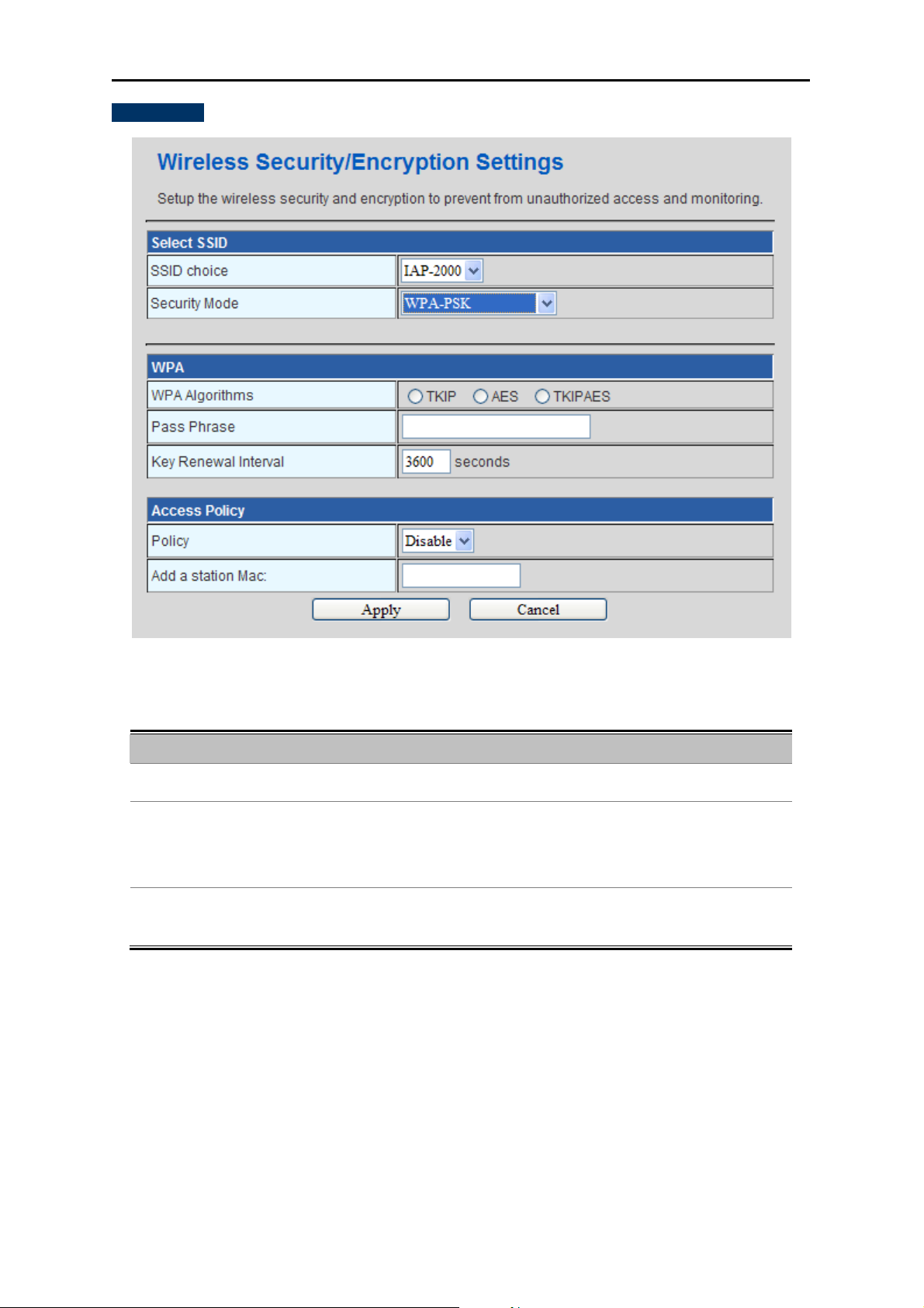
C. WPA-PSK
User’s Manual of IAP-200x Series
The page includes the following fields:
Object Description
WPA Algorithms :
Select TKIP, AES or TKIP
Set 8-bit to 64-bit key in ASCII characters.
Pass phrase :
You may select to select Passphrase (alphanumeric format) or Hexadecimal
Digits (in the “A-F”, “a-f” and “0-9” range) to be the Pre-shared Key.
Key Renewal
Please fill in a number for Group Key Renewal interval time.
al :
Interv
Figure 4-18 WPA-PSK
AES for WPA algorithms.
-47-
Page 49

D. WPA
User’s Manual of IAP-200x Series
The page includes the following fields:
Object Description
WPA Algorithms
Key Renewal Interval
IP Address
Select TKIP, AES or TKIPAES for WPA algorithms.
Please fill in a
Enter the RADIUS Server
Enter the RADIUS Server’s port number provided by your ISP.
Port
(The Default is 1812.)
Shared Secret
Enter the pa
Session timeout interval is for 802.1x re-authentication setting. Set to zero
Session Timeout
to disable 802.1x re-authentication service for each session. Session
Figure 4-19 WPA-RADIUS
number for Group Key Renewal interval time.
’s IP Address provided by your ISP.
ssword that the Wireless AP shares with the RADIUS Server.
-48-
Page 50

User’s Manual of IAP-200x Series
Idle Timeout
E. WPA2-PSK
timeout interval
Enter the idl
timeout in the column.
e
unit is second and must be larger than 60.
The page includes the following fields:
Object Description
WPA Algorithms :
Select TKIP, AES or TKIP
Set 8-bit to 64-bit key in ASCII characters.
Pass phrase :
You may select to select Passphrase (alphanumeric format) or Hexadecimal
Digits (in the “A-F”, “a-f” and “0-9” range) to be the Pre-shared Key.
y Renewal
Ke
Please fill in a number for Group Key Renewal interval time.
Interv
al :
Figure 4-20 WPA2-PSK
AES for WPA algorithms.
-49-
Page 51

F. W PA 2
User’s Manual of IAP-200x Series
The page includes the following fields:
Object Description
WPA Algorithms
Key Renewal Interval
Select TKIP, AES or TKIPAES for WPA algorithms.
Please fill in a
Only
PMK Cache Period
time out, the cached key will be deleted. PMK Cache Period unit is minute.
y valid in WPA2 security. The most important features beyond WPA to
Authentication
Pre-
Onl
become standardized through 802.11i/WPA2 are: Pre-authentication, which
Figure 4-21 WPA2-RADIUS
number for Group Key Renewal interval time.
valid in WPA2 security. Set WPA2 PMKID cache timeout period, after
-50-
Page 52

User’s Manual of IAP-200x Series
enables secure fast roaming without noticeable signal latency.
Shared Secret
Session Timeout
IP Address
Port
Shared Secret
Session Timeout
Idle Timeout
Enter the password that the Wireless AP shares with the RADIUS Server.
Session timeout interval is for 802.1x re-authentication setting. Set to zero
to disable 802.1x re-authentication service for each session. Session
timeout interval unit is second and must be larger than 60.
Enter the RADIUS Server’s IP Address provided by your ISP.
Enter the RADIUS Server’s port number provided by your ISP. (The Default
is 1812.)
Enter the password that the Wireless AP shares with the RADIUS
Server.
Session timeout interval is for 802.1x re-authentication setting. Set to zero
to disable 802.1x re-authentication service for each session. Session
timeout interval unit is second and must be larger than 60.
Enter the idle timeout in the column.
-51-
Page 53
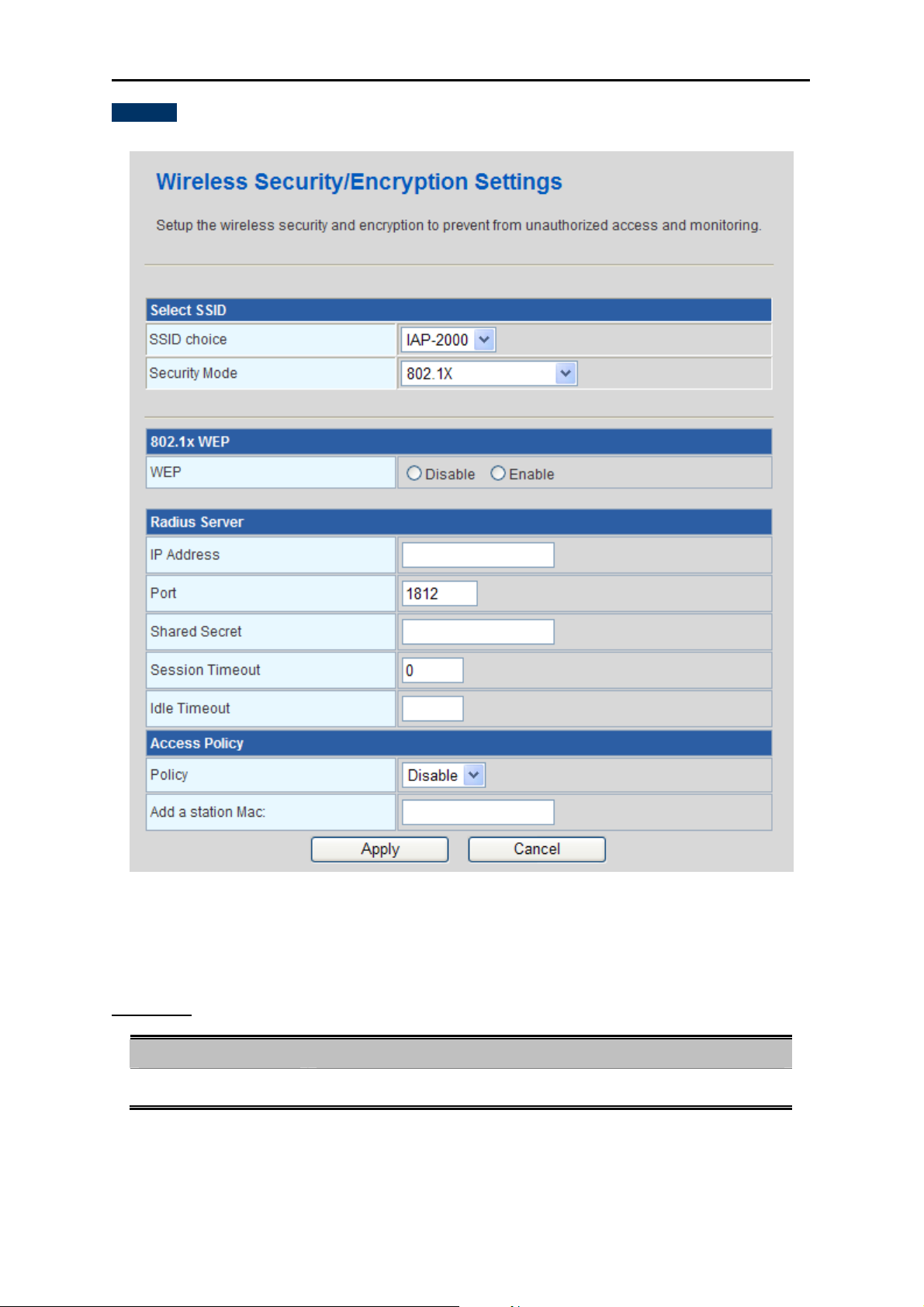
F. 802.1X
User’s Manual of IAP-200x Series
The page includes the following fields:
802.1X WEP
Object Description
WEP
Enable or Disable WEP encryption.
Figure 4-22 802.1X
-52-
Page 54

User’s Manual of IAP-200x Series
Radius Server
Object Description
IP Address:
Port:
Enter the IP address of Radius Server.
The default port of the RADIUS server for authentication is 1812. You need
not change this value unless your network administrator instructs you to do
so with additional information.
Shared Secret:
Enter a password as the key to be shared between the external
authentication server and the access point. The key is not send over the
network. This key must be the same on the external authentication server
and your router.
Session Timeout:
Idle Timeout:
Set the time interval for session. Enter the proper value in the field.
Set the idle time interval. Enter the proper value in the field.
In order to connect to the wireless AP successfully, the wireless settings (e.g. SSID) and
the security settings (e.g. encryption key) of the hosts in the wireless network should be
consistent with that of the wireless AP.
-53-
Page 55

User’s Manual of IAP-200x Series
4.5.4. WPS
Users can enable, disable, and configure the WPS (Wi-Fi Protected Setup) function in this page.
Figure 4-23
WPS Config
Object Description
WPS:
WPS Summary
It displays the WPS information, such as WPS Current Status, WPS Configured, and WPS SSID.
Object Description
Generate:
Reset OOB:
n enable or disable the WPS function in this field.
You ca
Generate a new PIN code for the IAP-2000
Reset to out of box (OoB) configuration.
-54-
Page 56

WPS Progress
Object Description
User’s Manual of IAP-200x Series
WPS mode:
PIN:
There are two way for you to enable WPS function:
PBC - You can use a push button configuration (PBC) on the Wi-Fi
router.
PIN - If there is no button, enter a 4- or 8-digit PIN code. Each STA
supporting WPS comes with a hard-coded PIN code.
If you select PIN mode, you need enter the PIN number in the field.
WPS Status
It displays the information about WPS status.
Click Apply to make the configuration take effect.
Configuration Example: To add a new device:
If the wireless adapter supports Wi-Fi Protected Setup (WPS), you can establish a wireless connection between
wireless adapter and Router using either Push Button Configuration (PBC) method or PIN method.
To build a successful connection by WPS, you should also do the corresponding configuration of
the new device for WPS function meanwhile.
I. By Push Button Configuration (PBC)
If the wireless adapter supports Wi-Fi Protected Setup and the Push Button Configuration (PBC) method, you can
add it to the network by PBC with the following two methods.
Step 1: Choose PBC, and click “Apply”.
Figure 4-24 WPS - PBC
Step 2: Press and hold the WPS Button equipped on the adapter directly for 2 or 3 seconds. Or you can click
the WPS button with the same function in the configuration utility of the adapter.
-55-
Page 57

User’s Manual of IAP-200x Series
Step 1 & 2 should process within two minutes.
Step 3: Wait for a while until the connection established to complete the WPS configuration.
II. By PIN
If the new device supports Wi-Fi Protected Setup and the PIN method, you can add it to the network by PIN with
the following two methods.
Method One: Enter the PIN of your Wireless adapter into the configuration utility of the Router
Step 1: Choose PIN, and enter the PIN code of the wireless adapter.
Figure 4-25 WPS – PIN of Wireless adapter
Please find the PIN code of the wireless adapter from the configuration utility of the WPS.
Step 2: For the configuration of the wireless adapter, please choose the option that you want to enter PIN into
the Router in the configuration utility of the WPS, and click Next.
Method Two: Enter the PIN of the Router into the configuration utility of your Wireless adapter
Step 1: Choose PIN option, and get the Current PIN code of the AP in WPS Summary table (each Router has
its unique PIN code).
-56-
Page 58

User’s Manual of IAP-200x Series
Figure 4-26 WPS – PIN of AP
Step 2: For the configuration of the wireless adapter, please choose the option that you want to enter the PIN
of the AP in the configuration utility of the Wireless adapter, and enter it into the field. Then click Next.
Step 3: You will see the WPS Current Status is “Configured” when the new device has successfully connected
to the network.
Figure 4-27 WPS – Configured
-57-
Page 59
User’s Manual of IAP-200x Series
The WPS function cannot be configured if the Wireless Function of the AP is disabled. Please
make sure the Wireless Function is enabled before configuring the WPS.
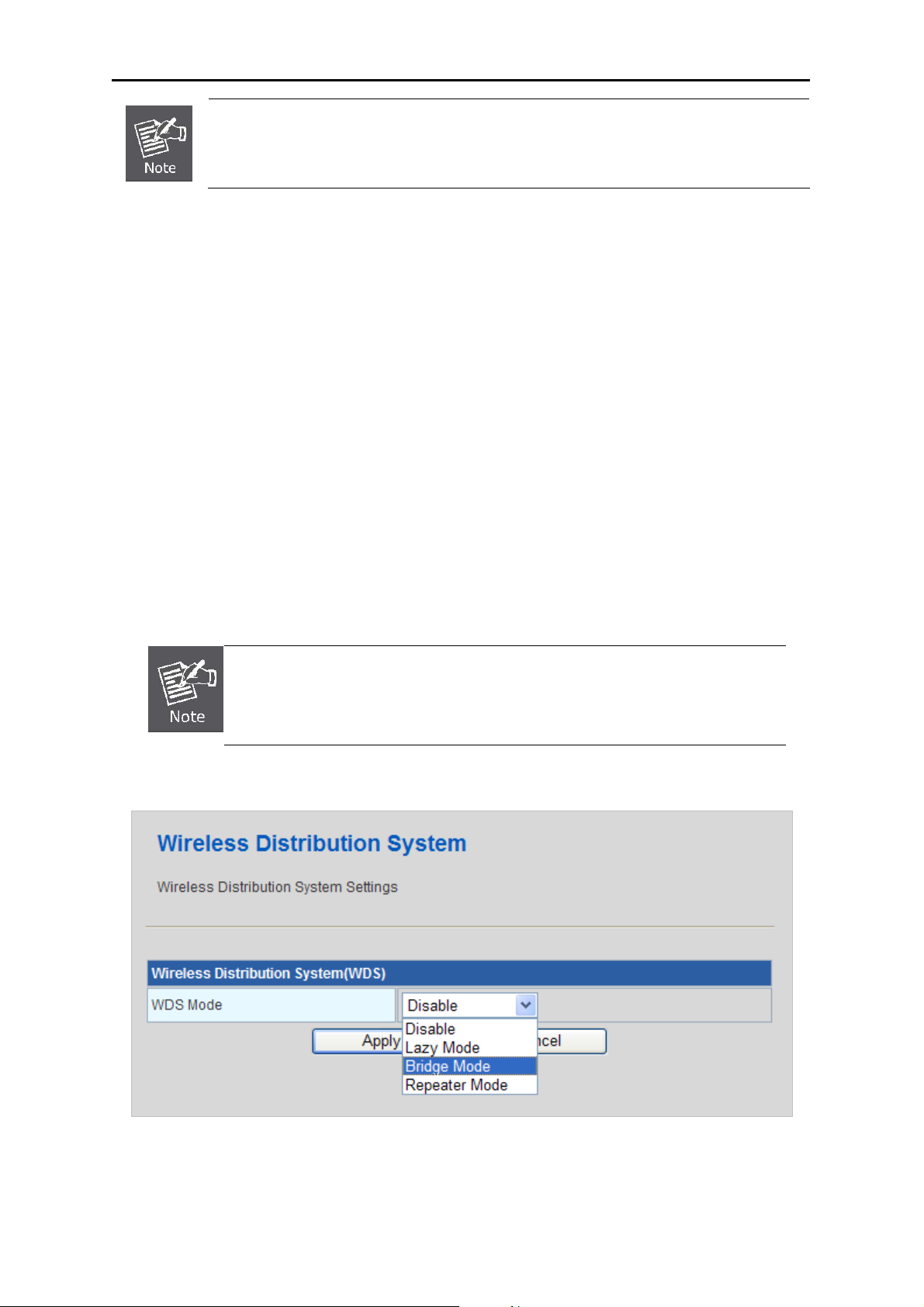
4.5.5. WDS
WDS (Wireless Distribution System) allows access points to communicate with one another wirelessly in a
standardized way. It can also simplify the network infrastructure by reducing the amount of cabling required.
Basically the access points will act as a client and an access point at the same time.
WDS is incompatible with WPA. Both features cannot be used at the same time. A WDS link is bi-directional, so
the AP must know the MAC address of the other AP, and the other AP must have a WDS link back to the AP.
Dynamically assigned and rotated encryption key are not supported in a WDS connection. This means that WPA
and other dynamic key assignment technologies may not be used. Only Static WEP keys may be used in a WDS
connection, including any STAs that are associated with a WDS repeating AP.
Enter the MAC address of the other APs that you want to link to and click enable.
Supports up to 4 point to multipoint WDS links, check Enable WDS and then enable on the MAC addresses.
To create and setup the WDS connection, you must set these APs in the same channel
and set MAC address of other APs which you want to communicate with in the table and
then enable the WDS.
Users can enable, disable, and configure the WDS function in this page.
Figure 4-18
-58-
Page 60

User’s Manual of IAP-200x Series
WDS Mode: There are four options, including Disable, Lazy Mode, Bridge Mode, and Repeater Mode.
Disable
Select Disable to disable the WDS mode.
Lazy Mode
Object Description
WDS Mode:
Select Lazy Mode. The IAP-200X WDS Lazy mode is allowed the other
IAP-200X WDS bridge / repeater mode link automatically.
Phy Mode:
Encryp Type:
It provides 4 options, including CCK, OFDM, HTMIX, and GREENFIELD.
It provides 4 options, including None, WEP, TKIP, and AES.
Figure 4-19
Lazy Mode Configuration
In the lazy mode, the wireless AP automatically connects to the WDS devices that use the same SSID, channel,
encryption mode, and the physical mode. You do not need to manually enter other MAC addresses of the peer
routers.
To configure the Lazy Mode, do as follows:
Step 1. In the Wireless Distribution System (WDS) page, set the WDS mode to be Lazy Mode.
Step 2. Set the entity model and encryption type to accord with the peer AP (A AP that needs to connect to the
wireless AP by WDS).
Step 3. After finishing the settings, click the Save button to save the settings. The wireless AP will work in the
Lazy mode.
Step 4. Enter the Wireless Security Settings page, and set the security mode of the wireless AP to accord with
the peer router.
-59-
Page 61

Bridge Mode/ Repeater Mode
Object Description
User’s Manual of IAP-200x Series
Figure 4-20
WDS Mode:
Phy Mode:
Encryp Type:
AP MAC Address:
Click Apply to make the configuration take effect. Click Cancel to cancel the new configuration.
Select Bridge Mode or Repeater Mode.
It provides 4 options, including CCK, OFDM, HTMIX, and GREENFIELD.
It provides 4 options, including None, WEP, TKIP, and AES.
It provides 4 AP MAC Address. Enter the MAC address of the other APs.
Bridge Mode Configuration
In the bridge mode, you can use the wireless AP to connect to other AP, for extending wireless coverage.
Meanwhile, it can also decrease the working load of the AP that accesses the Internet. In that case, the wireless
card does not directly communicate with the wireless device that accesses the Internet, but it directly
communicates with the wireless AP.
Step 1. In the Wireless Distribution System (WDS) page, select the WDS mode to be Bridge Mode.
Step 2. Set the entity model and encryption type to accord with the peer AP, and then enter the MAC address
of the peer AP.
Step 3. After finishing the settings, click the Save button to save the settings. The wireless AP will work in the
Bridge mode.
Step 4. Choose Wireless Settings > Wireless Security Settings to display the Wireless Security Settings page.
Set the security mode of the wireless AP to accord with the peer AP.
-60-
Page 62

User’s Manual of IAP-200x Series
Repeater Mode Configuration
In the Repeater mode, you can use the wireless AP to connect to the primary AP, for extending the wireless
coverage.
Step 1. Choose Wireless Settings Basic to display the Basic Settings page.
Figure 4-21
Step 2. In this page, set the channel of the wireless router to accord with the peer AP.
Step 3. In the Wireless Distribution System (WDS) page, set the WDS mode to Repeater Mode, set the Phy
mode, encryption type, and Encryption key to accord with the peer router. Then enter the MAC address
of the peer AP. After finishing the settings, click the Apply button to save the settings. The IAP-2000 will
work in the Repeater mode.
-61-
Page 63

User’s Manual of IAP-200x Series
Figure 4-22
Step 4. Choose Wireless Settings > Security to display the Wireless Security Settings page.
-62-
Page 64

User’s Manual of IAP-200x Series
Figure 4-23
Step 5. In this page, set the security mode of IAP-2000 to accord with the peer router.
4.5.6. Station List
The administrator can check the users connected to the IAP-2000 in this page.
Figure 4-24
Click Refresh button to renew the list above immediately.
-63-
Page 65

User’s Manual of IAP-200x Series
4.6. Layer 2 Functions
Users can configure the port setting and VLAN in this page. The submenus of Layer 2 Functions is shown below:
Figure 4-25
4.6.1. Port Status
Users can check the information of the connection on each port in this page.
Figure 4-26
Click Refresh button to renew the list above immediately.
-64-
Page 66

User’s Manual of IAP-200x Series
4.6.2. Port Setting
Users can enable or disable each port, and configure the related settings in this page.
Figure 4-27
Fast Ethernet Port Configuration
Object Description
Port
Mode:
Flow Control:
Port Enable:
Click Apply to make the configuration take effect. Click Cancel to cancel the new configuration.
This is the LAN port number for this row.
You can select Auto Negotiation, 100 Full, 100 Half, 10 Full, and 10 Half.
You can choose Enable or Disable.
Y
ou can choose Enable or Disable.
4.6.3. VLAN Setting
Setting up Virtual LAN on the IAP-2000 increases the efficiency of the network by dividing the LAN into logical
segments. The submenus of VLAN option is shown below:
-65-
Page 67

User’s Manual of IAP-200x Series
Figure 4-28
VLAN Mode Setting
Mode: You can enable or disable the VLAN here.
Management VID
VID: Set the management VLAN of the IAP-2000.
VLAN Member Configuration
Object Description
VLAN Group:
VID:
Port 1~4:
PVID:
Port Priority:
You can select enable or disable.
Set the VID here for each Virtual LAN.
It means the LAN port on the IAP-2000.
You can set the PVID for each port here.
You can decide the priority of each port here.
Click Apply to make the configuration take effect. Click Cancel to cancel the new configuration.
-66-
Page 68

4.6.4. MAC Address Table
It shows the MAC address for each port here.
User’s Manual of IAP-200x Series
Figure 4-29
Click Refresh button to renew the list above immediately.
4.7. System Tools
Users can configure the related settings of IAP-2000 system here. The submenus of System Tools option is shown
below:
Figure 4-30
-67-
Page 69

4.7.1. PoE Configuration
*This option is for IAP-2000PS only.
PoE (Power over Ethernet) Powered Devices:
Voice over IP phones
Enterprise can install POE VoIP Phone, ATA and other Ethernet/non-Ethernet
end-devices to the central where UPS is installed for un-interrupt power system
3~5 watts
and power control system.
Wireless LAN Access Points
User’s Manual of IAP-200x Series
Museum, Sightseeing, Airport, Hotel, Campus, Factory, Warehouse can
install the Access Point any where with no hesitation
6~12 watts
IP Surveillance
Enterprise, Museum, Campus, Hospital, Bank, can install IP Camera without
limits of install location – no need electrician to install AC sockets.
10~12 watts
PoE Splitter
PoE Splitter split the PoE 48V DC over the Ethernet cable into 5/9/12V DC
3~12 watts
power output. It frees the device deployment from restrictions due to power
outlet locations, which eliminate the costs for additional AC wiring and reduces
the installation time.
IAP-2000PS is a PoE device of End-span PSE. In this page, you can monitor the power consumption of each
device which is power supplied by IAP-2000PS and configure the related settings of PoE function.
-68-
Page 70

User’s Manual of IAP-200x Series
PoE Setting
Object Description
Power Limit Mode:
Power Budget:
PoE Function:
Priority
Device Class:
Allow to configure power limit mode for PoE PD devices connected with
IAP-2000PS.
Port Priority: Deliver PoE power by port priority setting.
Total Limi t : Set total limit value of all the POE ports to provide power
Show the total watts usage of PoE ports.
Enable or disable the PoE function of each port.
Set port priority for the POE power management
It can choose the “port priority”, value is “1~4”. High priority is “1”.
Class 0 is the default for PDs. However, to improve power management at
the PSE, the PD may opt to provide a signature for Class 1 to 3.
for the PDs.
The PD is classified based on power. The classification of the PD is the
-69-
Page 71

Current [mA]
User’s Manual of IAP-200x Series
maximum power that the PD will draw across all input voltages and
operational modes. A PD shall return Class 0 to 3 in accordance with the
maximum power draw.
It shows the current Amp of the PoE device.
Consumption [W]
Power Limit
It shows the current watt of the PoE device.
It can limit the watts supplied for each port.
The maximum value must be less than 15.4W per port, total value of all
ports must be less than the Power Reservation value.
Once power overload detected, the port will auto shut down and keep on
detection mode until PD’s power consumption lower than the power limit
value.
4.7.2. IPv6 Ping
This page allows you to issue ICMPv6 PING packets to troubleshoot IPv6 connectivity issues. After you press the
“Test” button, 5 ICMPv6 packets are transmitted, and the sequence number and roundtrip time will be displayed
upon reception of a reply. The page refreshes automatically until the responses to all packets are received, or until
a timeout occurs. The ICMPv6 Ping screen is as follows in Figure 4-12.
Figure 4-12 IPv6 Ping page screenshot
-70-
Page 72

Object Description
User’s Manual of IAP-200x Series
IPv6 Address
Test
Clear Message
The destination of IPv6 Address.
Click the button to start transmitting PING packets.
Clear the PING records below.
4.7.3. Upload Firmware
In this page, you may upgrade the correct new version firmware to obtain new functionality.
Figure 4-31
Update Firmware
Location: Click Browse to select the firmware file, and click Apply to upgrade the firmware.
If the firmware is uploaded in an improper way, the system would core dump.
4.7.4. Settings Management
You may save system settings by exporting them to a configuration file, restore them by importing the file, or reset
them to the factory default.
-71-
Page 73

User’s Manual of IAP-200x Series
Figure 4-32
Export Settings
Export Button: Click the Export to export the settings.
Import Settings
Settings file location: Click Browse to select the configuration file, and then click Import to upload
the configuration file. Click Cancel to cancel the uploading operation.
Load Factory Defaults
Load Default Button: Click Load Default to make AP return to the default settings.
4.7.5. Reboot
The Reboot screen allows you to restart your AP with its current settings.
-72-
Page 74

Figure 4-33
Click the “Reboot” button and the device will restart.
4.7.6. Statistics
User’s Manual of IAP-200x Series
It displays the information about AP status, including system information, Internet configurations, and
local network.
Figure 4-34
-73-
Page 75

User’s Manual of IAP-200x Series
4.8. System Log
The system log dialog allows you to view the system log and click the “Refresh” button to fresh the
system event logs. You are allowed to view and disable / enable the system log in this page.
Figure 4-35
Click Refresh to refresh the log. Click Clear to clear the log.
-74-
Page 76
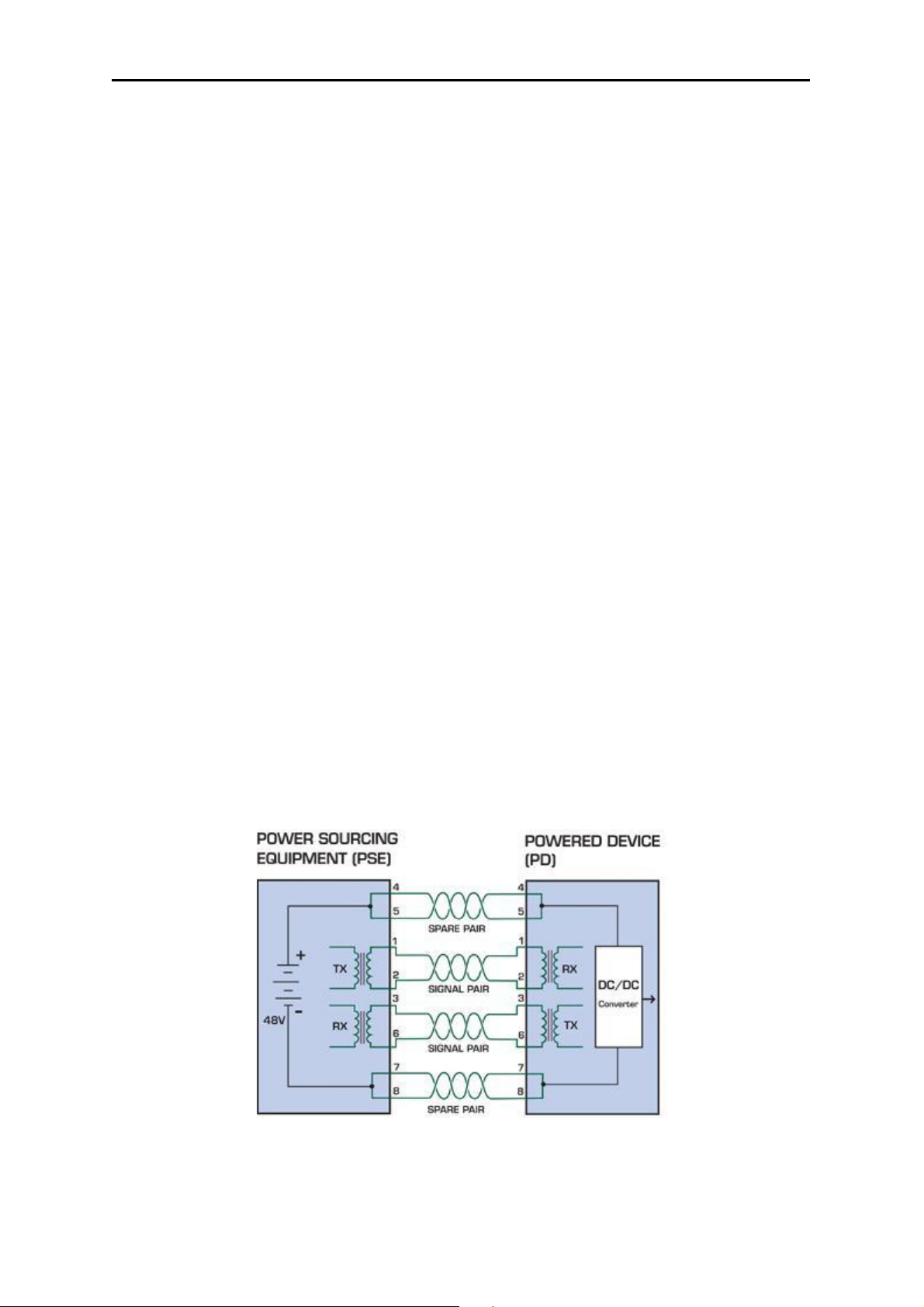
User’s Manual of IAP-200x Series
Chapter 5. PoE (Power over Ethernet) Overview
5.1. What is PoE?
Based on the global standard IEEE 802.3af, PoE is a technology for wired Ethernet, the most widely installed local
area network technology adopted today. PoE allows the electrical power necessary for the operation of each
end-device to be carried by data cables rather than by separate power cords. New network applications, such as
IP Cameras, VoIP Phones, and Wireless Networking, can help enterprises improve productivity. It minimizes wires
that must be used to install the network for offering lower cost, and less power failures.
IEEE802.3af also called Data Terminal equipment (DTE) power via Media dependent interface (MDI) is an
international standard to define the transmission for power over Ethernet. The 802.3af is delivering 48V power
over RJ-45 wiring. Besides 802.3af also define two types of source equipment: Mid-Span and End-Span.
Mid-Span
Mid-Span device is placed between legacy switch and the powered device. Mid-Span is tap the unused wire
pairs 4/5 and 7/8 to carry power, the other four is for data transmit.
End-Span
End-Span device is direct connecting with power device. End-Span could also tap the wire 1/2 and 3/6.
PoE System Architecture
The specification of PoE typically requires two devices: the Powered Source Equipment (PSE) and the Powered
Device (PD). The PSE is either an End-Span or a Mid-Span, while the PD is a PoE-enabled terminal, such as IP
Phones, Wireless LAN, etc. Power can be delivered over data pairs or spare pairs of standard CAT-5 cabling.
How Power is Transferred through the Cable
A standard CAT5 Ethernet cable has four twisted pairs, but only two of these are used for 10BASE-T and
100BASE-T. The specification allows two options for using these cables for power, shown in Figure 2 and Figure 3:
The spare pairs are used. Figure 2 shows the pair on pins 4 and 5 connected together and forming the positive
supply, and the pair on pins 7 and 8 connected and forming the negative supply. (In fact, a late change to the spec
allows either polarity to be used).
Figure 5-1 Power Supplied over the Spare Pins
The data pairs are used. Since Ethernet pairs are transformer coupled at each end, it is possible to apply DC
power to the center tap of the isolation transformer without upsetting the data transfer. In this mode of operation
the pair on pins 3 and 6 and the pair on pins 1 and 2 can be of either polarity.
-75-
Page 77

User’s Manual of IAP-200x Series
Figure 5-2 Power Supplied over the Data Pins
When to install PoE?
Consider the following scenarios:
• You're planning to install the latest VoIP Phone system to minimize cabling building costs when your company
moves into new offices next month.
• The company staff has been clamoring for a wireless access point in the picnic area behind the building so they
can work on their laptops through lunch, but the cost of electrical power to the outside is not affordable.
• Management asks for IP Surveillance Cameras and business access systems throughout the facility, but they
would rather avoid another electrician's payment.
-76-
Page 78

User’s Manual of IAP-200x Series
5.2. PoE Provision Process
While adding PoE support to networked devices is relatively painless, it should be realized that power cannot
simply be transferred over existing CAT-5 cables. Without proper preparation, doing so may result in damage to
devices that are not designed to support provision of power over their network interfaces.
The PSE is the manager of the PoE process. In the beginning, only small voltage level is induced on the port's
output, till a valid PD is detected during the Detection period. The PSE may choose to perform classification, to
estimate the amount of power to be consumed by this PD. After a time-controlled start-up, the PSE begins
supplying the 48 VDC level to the PD, till it is physically or electrically disconnected. Upon disconnection, voltage
and power shut down.
Since the PSE is responsible for the PoE process timing, it is the one generating the probing signals prior to
operating the PD and monitoring the various scenarios that may occur during operation.
All probing is done using voltage induction and current measurement in return.
Stages of powering up a PoE link
Stage Action
Detection
Classification
Startup
Normal operation
Volts specified
per 802.3af
Measure whether powered device has the correct
2.7-10.0 1.8–10.0
signature resistance of 15–33 kΩ
Measure which power level class the resistor indicates 14.5-20.5 12.5–25.0
Where the powered device will startup >42 >38
Supply power to device 36-57 25.0–60.0
Volts managed
by chipset
1. Line Detection
Before power is applied, safety dictates that it must first be ensured that a valid PD is connected to the PSE's
output. This process is referred to as "line detection", and involves the PSE seeking a specific, 25 KΩ signature
resistor. Detection of this signature indicates that a valid PD is connected, and that provision of power to the
device may commence.
The signature resistor lies in the PD's PoE front-end, isolated from the rest of the the PD's circuitries till detection
is certified.
2. Classification
Once a PD is detected, the PSE may optionally perform classification, to determine the maximal power a PD is to
consume. The PSE induces 15.5-20.5 VDC, limited to 100 mA, for a period of 10 to 75 ms responded by a certain
current consumption by the PD, indicating its power class.
The PD is assigned to one of 5 classes: 0 (default class) indicates that full 15.4 watts should be provided, 1-3
indicate various required power levels and 4 is reserved for future use. PDs that do not support classification are
assigned to class 0. Special care must be employed in the definition of class thresholds, as classification may be
affected by cable losses.
Classifying a PD according to its power consumption may assist a PoE system in optimizing its power distribution.
Such a system typically suffers from lack of power resources, so that efficient power management based on
classification results may reduce total system costs.
-77-
Page 79

User’s Manual of IAP-200x Series
3. Start-up
Once line detection and optional classification stages are completed, the PSE must switch from low voltage to its
full voltage capacity (44-57 Volts) over a minimal amount of time (above 15 microseconds).
A gradual startup is required, as a sudden rise in voltage (reaching high frequencies) would introduce noise on the
data lines.
Once provision of power is initiated, it is common for inrush current to be experienced at the PSE port, due to the
PD’s input capacitance. A PD must be designed to cease inrush current consumption (of over 350 mA) within 50
ms of power provision startup.
4. Operation
During normal operation, the PSE provides 44-57 VDC, able to support a minimum of 15.4 watts power.
Power Overloads
The IEEE 802.3af standard defines handling of overload conditions. In the event of an overload (a PD drawing a
higher power level than the allowed 12.95 Watts), or an outright short circuit caused by a failure in cabling or in the
PD, the PSE must shut down power within 50 to 75 milliseconds, while limiting current drain during this period to
protect the cabling infrastructure. Immediate voltage drop is avoided to prevent shutdown due to random
fluctuations.
5. Power Disconnection Scenarios
The IEEE 802.3af standard requires that devices powered over Ethernet be disconnected safely (i.e. power needs
be shut down within a short period of time following disconnection of a PD from an active port).
When a PD is disconnected, there is a danger that it will be replaced by a non-PoE-ready device while power is
still on. Imagine disconnecting a powered IP phone utilizing 48 VDC, then inadvertently plugging the powered
Ethernet cable into a non-PoE notebook computer. What’s sure to follow is not a pretty picture.
The standard defines two means of disconnection, DC Disconnect and AC Disconnect, both of which provide the
same functionality - the PSE shutdowns power to a disconnected port within 300 to 400ms. The upper boundary is
a physical human limit for disconnecting one PD and reconnecting another.
DC Disconnect
DC Disconnect detection involves measurement of current. Naturally, a disconnected PD stops consuming current,
which can be inspected by the PSE. The PSE must therefore disconnect power within 300 to 400 ms from the
current flow stop. The lower time boundary is important to prevent shutdown due to random fluctuations.
AC Disconnect
This method is based on the fact that when a valid PD is connected to a port, the AC impedance measured on its
terminals is significantly lower than in the case of an open port (disconnected PD).
AC Disconnect detection involves the induction of low AC signal in addition to the 48 VDC operating voltage. The
returned AC signal amplitude is monitored by the PSE at the port terminals. During normal operation, the PD's
relatively low impedance lowers the returned AC signal while a sudden disconnection of this PD will cause a surge
to the full AC signal level and will indicate PD disconnection.
-78-
Page 80

User’s Manual of IAP-200x Series
Appendix A. Networking Connection
A.1. DATA OUT PoE Switch RJ-45 Port Pin Assignments (Port-1 to
Port-4)
PIN NO RJ-45 SIGNAL ASSIGNMENT
1 Output Transmit Data +
Power +
2 Output Transmit Data –
Power +
3 Receive Data +
Power -
4 5 6 Receive Data –
Power -
7 8 -
Figure A-1
A.2. 10/100Mbps, 10/100Base-TX
When connecting your 10/100Mbps Ethernet Switch to another switch, a bridge or a hub, a straight or crossover
cable is necessary. Each port of the Switch supports auto-MDI/MDI-X detection. That means you can directly
connect the Switch to any Ethernet devices without making a crossover cable. The following table and diagram
show the standard RJ-45 receptacle/ connector and their pin assignments:
RJ-45 Connector pin assignment
MDI
Contact
Media Dependant Interface
1 Tx + (transmit) Rx + (receive)
2 Tx - (transmit) Rx - (receive)
3 Rx + (receive) Tx + (transmit)
4, 5 Not used
6 Rx - (receive) Tx - (transmit)
7, 8 Not used
MDI-X
Media Dependant Interface-Cross
-79-
Page 81

The standard cable, RJ-45 pin assignment
Figure A-2 The standard RJ-45 receptacle/connector
User’s Manual of IAP-200x Series
There are 8 wires on a standard UTP/STP cable and each wire is color-coded. The following shows the pin
allocation and color of straight cable and crossover cable connection:
Straight Cable SIDE 1 SIDE2
1 = White / Orange
2 = Orange
3 = White / Green
4 = Blue
5 = White / Blue
6 = Green
7 = White / Brown
8 = Brown
12345678
12345678
SIDE 1
SIDE 2
1 = White / Orange
2 = Orange
3 = White / Green
4 = Blue
5 = White / Blue
6 = Green
7 = White / Brown
8 = Brown
Straight Cable SIDE 1 SIDE2
1 = White / Green
2 = Green
3 = White / Orange
4 = Blue
5 = White / Blue
6 = Orange
7 = White / Brown
8 = Brown
12345678
12345678
SIDE 1
SIDE 2
1 = White / Orange
2 = Orange
3 = White / Green
4 = Blue
5 = White / Blue
6 = Green
7 = White / Brown
8 = Brown
Figure A-3: Straight-Through and Crossover Cable
Please make sure your connected cables are with same pin assignment and color as above picture before
deploying the cables into your network.
-80-
Page 82

User’s Manual of IAP-200x Series
EC Declaration of Conformity
English Hereby, PLANET Technology Corporation,
declares that this Industrial 802.11n Wireless AP is
in compliance with the essential requirements and
other relevant provisions of Directive 1999/5/EC.
Česky Společnost PLANET Technology Corporation,
tímto prohlašuje, že tato Industrial 802.11n
Wireless AP splňuje základní požadavky a další
příslušná ustanovení směrnice 1999/5/EC.
Dansk PLANET Technology Corporation, erklærer
herved, at følgende udstyr Industrial 802.11n
Wireless AP overholder de væsentlige krav og
øvrige relevante krav i direktiv 1999/5/EF
Deutsch Hiermit erklärt PLANET Technology Corporation,
dass sich dieses Gerät Industrial 802.11n
Wireless AP in Übereinstimmung mit den
grundlegenden Anforderungen und den anderen
relevanten
Vorschriften der Richtlinie 1999/5/EG befindet".
(BMWi)
Eesti keeles Käesolevaga kinnitab PLANET Technology
Corporation, et see Industrial 802.11n Wireless
AP vastab Euroopa Nõukogu direktiivi 1999/5/EC
põhinõuetele ja muudele olulistele tingimustele.
Ελληνικά
Español
Français Par la présente, PLANET Technology Corporation,
Italiano Con la presente , PLANET Technology
Latviski
ΜΕ ΤΗΝ ΠΑΡΟΥΣΑ , PLANET Technology
Corporation, ΔΗΛΩΝΕΙ ΟΤΙ ΑΥΤ Ο Industrial
802.11n Wireless AP ΣΥΜΜΟΡΦΩΝΕΤΑΙ ΠΡΟΣ
ΤΙΣ ΟΥΣΙΩΔΕΙΣ ΑΠΑΙΤΗΣΕΙΣ ΚΑΙ ΤΙΣ ΛΟΙΠΕΣ
ΣΧΕΤΙΚΕΣ ΔΙΑΤΑΞΕΙΣ ΤΗΣ ΟΔΗΓΙΑΣ 1999/5/ΕΚ
Por medio de la presente, PLANET Technology
Corporation, declara que Industrial 802.11n
Wireless AP cumple con los requisitos esenciales y
cualesquiera otras disposiciones aplicables o
exigibles de
la Directiva 1999/5/CE
déclare que les appareils du Industrial 802.11n
Wireless AP sont conformes aux exigences
essentielles et aux autres dispositions pertinentes de
la directive 1999/5/CE
Corporation, dichiara che questo Industrial
802.11n Wireless AP è conforme ai requisiti
essenziali ed alle altre disposizioni pertinenti stabilite
dalla direttiva. 1999/5/CE.
Ar šo PLANET Technology Corporation, apliecina,
ka šī Industrial 802.11n Wireless AP atbilst
Direktīvas 1999/5/EK pamatprasībām un citiem
atbilstošiem noteikumiem.
Lietuviškai Šiuo PLANET Technology Corporation,, skelbia,
kad Industrial 802.11n Wireless AP tenkina visus
svarbiausius 1999/5/EC direktyvos reikalavimus ir
kitas svarbias nuostatas.
Magyar A gyártó PLANET Technology Corporation,
kijelenti, hogy ez a Industrial 802.11n Wireless
AP megfelel az 1999/5/EK irányelv
alapkövetelményeinek és a kapcsolódó
rendelkezéseknek.
Malti Hawnhekk, PLANET Technology Corporation,
jiddikjara li dan Industrial 802.11n Wireless AP
jikkonforma mal-ħtiġijiet essenzjali u ma
provvedimenti oħrajn relevanti li hemm fid-Dirrettiva
1999/5/EC
Nederlands Hierbij verklaart , PLANET Technology orporation,
dat Industrial 802.11n Wireless AP in
overeenstemming is met de essentiële eisen en de
andere relevante bepalingen van richtlijn 1999/5/EG
Polski Niniejszym firma PLANET Technology
Corporation, oświadcza, że Industrial 802.11n
Wireless AP spełnia wszystkie istotne wymogi i
klauzule zawarte w dokumencie „Directive
1999/5/EC”.
Português PLANET Technology Corporation, declara que
este Industrial 802.11n Wireless AP está
conforme com os requisitos essenciais e outras
disposições da Directiva 1999/5/CE.
Slovensky
Slovensko PLANET Technology Corporation, s tem potrjuje,
Suomi PLANET Technology Corporation, vakuuttaa täten
Svenska
Výrobca PLANET Technology Corporation, týmto
deklaruje, že táto Industrial 802.11n Wireless AP
je v súlade so základnými požiadavkami a ďalšími
relevantnými predpismi smernice 1999/5/EC.
da je ta Industrial 802.11n Wireless AP
skladen/a z osnovnimi zahtevami in ustreznimi
določili Direktive 1999/5/EC.
että Industrial 802.11n Wireless AP tyyppinen
laite on direktiivin 1999/5/EY oleellisten vaatimusten
ja sitä koskevien direktiivin muiden ehtojen
mukainen.
Härmed intygar, PLANET Technology Corporation,
att denna Industrial 802.11n Wireless AP står i
överensstämmelse med de väsentliga
egenskapskrav och övriga relevanta bestämmelser
som
framgår av direktiv 1999/5/EG.
-81-
 Loading...