

Page 1

User’s Manual of HPOE-1200G / HPOE2400G
User’s Manual
HPOE-1200G
HPOE-2400G
IEEE 802.3at
12 / 24-Port Gigabit Power over Ethernet
Managed Injector Hub
1
Page 2

User’s Manual of HPOE-1200G / HPOE2400G
Trademarks
Copyright PLANET Technology Corp. 2011
Contents subject to which revision without prior notice.
PLANET is a registered trademark of PLANET Technology Corp. All other trademarks belong to their respective
owners.
Disclaimer
PLANET Technology does not warrant that the hardware will work properly in all environments and applications, and
makes no warranty and representation, either implied or expressed, with respect to the quality, performance,
merchantability, or fitness for a particular purpose.
PLANET has made every effort to ensure that this User’s Manual is accurate; PLANET disclaims liability for any
inaccuracies or omissions that may have occurred.
Information in this User’ s Manual is sub ject to chan ge without not ice and does no t represe nt a commit ment on the par t
of PLANET. PLANET assumes no responsibility for any inaccuracies that may be contained in this User’s Manual.
PLANET makes no comm itment to update or keep current th e inform ation in this User’ s Manual, and r eserves the r ight
to make improvements to this User’s Manual and/or to the products described in this User’s Manual, at any time
without notice.
If you find information in t his m anual that is incorrect, mislead ing, or in com plet e, we would appreciate your comm en t s
and suggestions.
FCC Warning
This equipment has been tes ted and fou nd to comply w ith the limit s for a Cl ass A digit al devi ce, pur suant to Par t 15 of
the FCC Rules. These limits are designed to provide reasonable protection against harmful interference when the
equipment is operated in a commercial e nvironment. This equipment generates, u ses, and can r adiate radio fr equency
energy and, if not installed and used in accordance with the Instruction manual, may cause harmful interference to
radio communications. O peration of this equi pment in a re sidential are a is likely to cause harmful interferen ce in whic h
case the user will be required to correct the interference at whose own expense.
CE Mark Warning
This is a Class A pr oduct. In a domestic env ironment, t his product may cause rad io interfere nce, in w hich case the us er
may be required to take adequate measures.
Energy Saving Note of the Device
This power required device does not support Standby mode operation.
For energy saving, please remove the power cable to disconnect the device from the power circuit.
Without removing power cabl e , the dev i ce will still consuming pow er fr om the p ower source. In the view of Saving t he
Energy and reduce the unnecessary power co nsuming, it is strongly suggested to remove the pow er connect ion for the
device if this device is not intended to be active.
WEEE Warning
To avoid the potential effects on the environment and human health as a result of the presence of
hazardous substances in electrical and electronic equipment, end users of electrical and electronic
equipment should understan d the mea nin g of the cross ed-out wheeled bin symbol . Do not dispose of
WEEE as unsorted municipal waste and have to collect suc h WEEE separat ely
Revision
PLANET IEEE 802.3at Power over Gigabit Ethernet Managed Injector Hub User's Manual
FOR MODELS:
REVISION: 1.0 (JANUARY.2011)
Part No.: 2080-AF0270-000
HPOE-1200G / HPOE-2400G
2
Page 3

User’s Manual of HPOE-1200G / HPOE2400G
TABLE OF CONTENTS
1. INTRODUCTION ............................................................................................................. 5
1.1 PACKAGE CONTENTS .................................................................................................................................. 5
1.2
PRODUCT DESCRIPTION .............................................................................................................................. 5
1.3 HOW TO USE THIS MANUAL ........................................................................................................................ 7
1.4
PRODUCT FEATURES .................................................................................................................................. 8
1.5
PRODUCT SPECIFICATIONS ....................................................................................................................... 10
2. INSTALLATION ............................................................................................................ 12
2.1 HARDWARE DESCRIPTION ......................................................................................................................... 12
2.1.1 Injector Front Panel
2.1.2 LED Indicators
2.1.3 Injector Rear Panel
.......................................................................................................................... 12
.................................................................................................................................. 13
.......................................................................................................................... 13
2.2
INSTALLING THE POE INJECTOR HUB ......................................................................................................... 14
2.2.1 Desktop Installation
2.2.2 Rack Mounting
2.2.3 Network Application Installation
2.2.4 Power over Ethernet Powered Device
3 Management .................................................................................................................. 18
3.1 OVERVIEW ................................................................................................................................................ 18
3.2
REQUIREMENTS ........................................................................................................................................ 18
3.3
MANAGEMENT METHOD ............................................................................................................................ 19
3.3.1 Web Management
3.3.2 PLANET Smart Discovery Utility
4 WEB CONFIGURATION ................................................................................................ 22
4.1 MANIN MENU ............................................................................................................................................ 22
4.2 WEB PANEL ............................................................................................................................................. 23
4.3
SYSTEM ................................................................................................................................................... 23
4.3.1 System Information
4.3.2 IP Configuration
4.3.3 NTP Configuration
4.3.4 Password Setting
4.3.5 Firmware Upgrade
4.3.6 Configuration Setting
4.3.7 Factory Default
4.3.8 System Log
4.3.9 System Reboot
4.3.10 Logout
.......................................................................................................................... 14
................................................................................................................................. 14
....................................................................................................... 16
............................................................................................. 17
............................................................................................................................ 19
...................................................................................................... 20
.......................................................................................................................... 24
............................................................................................................................... 25
............................................................................................................................ 26
............................................................................................................................. 27
........................................................................................................................... 28
........................................................................................................................ 29
................................................................................................................................. 32
...................................................................................................................................... 34
................................................................................................................................. 35
............................................................................................................................................ 35
4.4
SNMP ..................................................................................................................................................... 37
3
Page 4

User’s Manual of HPOE-1200G / HPOE2400G
4.4.1 SNMP Management ......................................................................................................................... 37
4.5
POWER OVER ETHERNET ........................................................................................................................... 39
4.5.1 PoE Configuration
4.5.2 PoE Schedule profile
4.5.3 PoE Schedule
4.5.4 PoE Schedule Profile configuration ex ample
5. Power OVER Ethernet Overview ................................................................................ 49
6. The PoE Provision Process ........................................................................................ 52
6.1 LINE DETECTION ....................................................................................................................................... 52
6.2
CLASSIFICATION ....................................................................................................................................... 52
6.3
START-UP ................................................................................................................................................. 53
6.4 OPERATION .............................................................................................................................................. 53
6.5
POWER DISCONNECTION SCENARIOS ........................................................................................................ 53
............................................................................................................................ 40
........................................................................................................................ 42
.................................................................................................................................. 44
................................................................................... 45
APPENDIX A ..................................................................................................................... 55
A.1 MDI SETTINGS ......................................................................................................................................... 55
A.2
POWER DEVICE CLASSIFICATION VALUES .................................................................................................. 55
A.3
DATA OUT POE INJECTOR RJ-45 PORT PIN ASSIGNMENTS ..................................................................... 56
4
Page 5

User’s Manual of HPOE-1200G / HPOE2400G
1. INTRODUCTION
1.1 Package Contents
CHECK THE CONTENTS OF YOUR PACKAGE FOR FOLLOWING PARTS:
● The PoE Injector Hub x 1
● The Quick Installation Guide x 1
● User’s Manual CD x 1
● Power Cord x 1
● Rubber Feet x 4
● Two Rack-mounting brackets with attachment screw x1 (set)
If any of these are m is sin g or damaged, please contact y o ur dealer immediately, if p os sib le, r etain th e c ar ton in cl udi ng the
original packing material, and use them against to repack the product in case there is a need to return it to us for repair.
In the following sectio n, th e ter m “PoE I nject or Hub ” means the two Gigabit PoE Inject or H ub devi ces, i.e. HPOE-1200G,
HPOE-2400G. Terms with lower case “injector” means any IEEE 802.3at / 802.3af power injectors. “PD” means the
abbreviated from IEEE 802.3at / 802.3af powered device.
1.2 Product Description
The PoE Injector Hub are 12 / 24-Port IEEE 802.3at / 802.3af Power over Ethernet Mid-Span injector hub complies with
IEEE 802.3, IEEE 802.3u, IEEE 802.3ab, IEEE 802.3at and IEEE 802.3af standards. It is equipped with 12 / 24
10/100/1000Mbps Gigabit Ethernet ports that support full 52V DC power for any remote IEEE 802.3at / 802.3af powered
device (PD) like 802.11b/g/n Wireless LAN Access Point, IP phone, LAN Camera or any other network devices. The PoE
Injector Hub should provide the sufficient 30.8 / 15.4 Watts power each port to the 12 / 24 remote PD devices with 460 / 340
Watts power supply.
The PoE Injector Hub is installed between a regular Ethernet switch and the powered devices, injecting power without
affecting the data transmit. It offer a cost effective solution and quickly way to upgrade network system to IEEE 802.3at /
802.3af Power over Ethernet, without replace the existing Ethernet Switch.
There are 24 / 48 RJ-45 STP ports o n th e fr on t pa nel of PoE Injector Hub, 12 / 24 of th em on lower stack are "Data" ports
and the other 12 / 24 ports on upper stack are "Data + Power output" ports. Each of th e "Data + Power output" port on
upper stack functions as an injector which inserts DC Voltage into the CAT 5e/6 cable allowing the cable between the
Injector and Splitter to transfer data and power simultaneously.
To manage your powered devices, the PoE Injector Hub provides both Web management interfaces in which
administrators can manage functions such as port Enable/Disable, port priority, limit, schedule, system configuration,
Username/Password ch anging and w ith s mart fe ature for power ed dev ice, t he PoE Injector Hub can auto detect the pow er
status on each port and s how massages Web managem ent i nterfa ce. T hese f eature s als o pr ovided a cost-effective way to
manage the devices from Internet whenever you are at work or at home.
5
Page 6
User’s Manual of HPOE-1200G / HPOE2400G
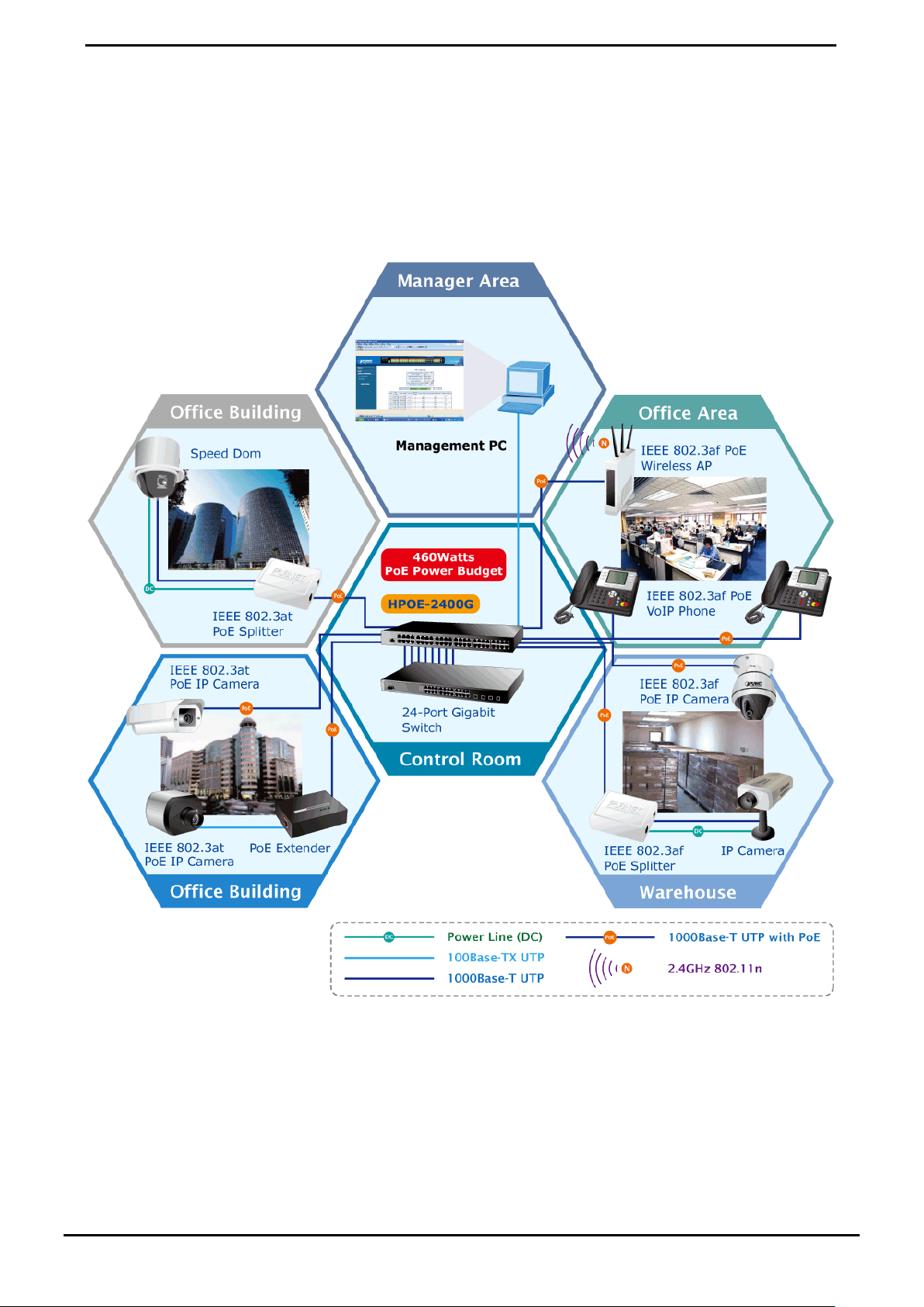
Power over Ethernet Applications
For the places hard to find the power outlet, the PoE Injector Hub provides the easiest w ay to pow er y our Ethern et devi ces
such as PLANET Internet Cameras and outdoor Wireless Access Point installed on the top of the building.
To control the power system of your networking devices, the Gigabit PoE Injector Hub can directly co-work with PoE IP
Phone to build VoIP telephony network in the office. Furthermore, the Gigabit PoE Injector H ub can be directly conne cted to
any third party 802.3at / 802.3af devices and PoE Switches installed 100 meters away.
Figure 1: PoE Injector Hub Application
6
Page 7

User’s Manual of HPOE-1200G / HPOE2400G
1.3 How to Use This Manual
This User Manual is structured as follows:
Section 2, Installation
It explains the functions of PoE Injector Hub and how to physically install the PoE Injector Hub.
Section 3, Management
It contains information about the software function of the PoE Injector Hub.
Section 4, Web Configuration
The section explains how to manage the PoE Injector H ub through Web interface.
Section 5, Power over Ethernet overview
The section explains the Power over Ethernet theories.
Section 6, PoE power Provision Process
The section explains the PoE power provision process.
Section 7, Troubleshooting
The section contains troubleshooting guide of the PoE Injector Hub.
Appendix A
It contains cable information of PoE Injector Hub.
7
Page 8

1.4 Product Features
Physical Port
HPOE-1200G
24-Port RJ-45
12 -Port 10/100/1000Mbps “Data input”
12 -Port 10/100/1000Mbps “Data + Power output”
1-Port 10/100Base-TX Management Port
Reset button for system management
HPOE-2400G
48-Port RJ-45
24 -Port 10/100/1000Mbps “Data input”
24 -Port 10/100/1000Mbps “Data + Power output”
1-Port 10/100Base-TX Management Port
Reset button for system management
User’s Manual of HPOE-1200G / HPOE2400G
Power over Ethernet
Complies with IEEE 802.3, IEEE 802.3at and IEEE 802.3af Power over Ethernet Mid-Span PSE
Up to 24 IEEE 802.3at / 802.3af devices pow ered
Supports PoE power up to 30.8Watts / 15.4 Watts for each PoE ports
Automatically detect powered device (PD)
Circuit protection prevent power interfer e nce betw een ports
Remote power feeding up to 100m
PoE Management
Total PoE power budget control
Per port PoE power schedule
PoE function enable / disable
Per port PoE function enable / disable
Per port 802.3at / 802.3af mode switch
PoE port power feeding priority
Per PoE port power limit
PD classification detection
Over Temperature Protection
PoE Temperature Threshold
PoE power Usage Threshold
Management
Web interface for remote management
Supports Network Time Protocol (NTP)
Firmware upgrade through Web interface
PLANET Smart Discovery utility automatically finds PLANET devices on the network
SNMP Trap for alarm notification of events
System Log / Remote Syslog
8
Page 9

Hardware
19-inch rack mountable; 1U height
Reset button for reset to default setting and system reboot
LED indicators for PoE ready and PoE act iv it y
LED indicators for Power Alert and Fan Alert
FCC Part 15 Class A, CE
Standard Compliance
IEEE 802.3 10Base-T
IEEE 802.3u 100Base-TX
IEEE 802.3ab 1000B as e-T
IEEE 802.3at pre-standard Power over Ethernet
IEEE 802.3af Power over Ethernet
User’s Manual of HPOE-1200G / HPOE2400G
9
Page 10
User’s Manual of HPOE-1200G / HPOE2400G
“Data” Input Ports
“Data+Power” Output Ports
Cooling
3 can be powered
can be powered
can be powered
Management Interface
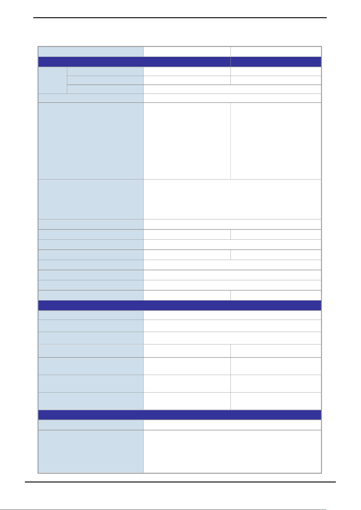
1.5 Product Specifications
Product HPOE-1200G HPOE-2400G
Hardware
12 x RJ-45 24 x RJ-45
Interface
Management Port 1 x RJ-45; 10/100Base-TX, auto-negotiation, auto-MDI / MDIX
Data Rate 10/100/1000Mbps
System: SYS Power x 1 (Green)
Management Port x2: 10/100
(Green / Orange)
LED
Network Cable
Per PoE Port: PoE in use x 1
(Green)
PoE Fail x 1
FAN Fail x 1
12 x RJ-45 24 x RJ-45
System: SYS Power x 1 (Green)
Management Port x2: 10/100
(Green / Orange)
Per PoE Port: PoE in use x 1
(Green)
PoE1 Fail x 1
PoE2 Fail x 1
FAN1 Fail x 1
FAN2 Fail x 1
10Base-T: 4-Pair UTP Cat. 5 up to 100m (328ft)
100Base-TX: 4-Pair UTP Cat. 5 up to 100m (328ft)
1000Base-T: 4-Pair UTP Cat. 5e, 6, up to 100m (328ft)
EIA/TIA- 568 100-ohm STP (100m)
Dimension (W x D x H)
Weight
Power Requirement
Power Consumption
Operating Temperature
Storage Temperature
Humidity
Power over Ethernet
PoE Power supply Type
PoE Power Output Per Port DC 52V 30.8 / 15.4 Watts
Power Pin Assignment 4/5(+), 7/8(-)
PoE Power Budget 340 Watts 460 Watts
370 Watts max. 490 Watts max.
Number of 802.3af PD Class 0, 1, 2,
Number of 802.3at PD Class 1, 2, 3
Number of 802.3at PD Class 0, 4
440 x 300 x 44 mm (1U height)
4.27kg 5.08kg
100-240V AC, 50/60 Hz
0 ~ 50 Degree C
-10 ~ 70 Degree C
5 ~ 95% (Non-condensing)
Fan x 2 Fan x 3
Mid-Span
12 24
12 24
10 14
Management
PoE Management
Web, PLANET Smart Discovery Lite
Power Limit by Priority and Total Limit
Per port power schedule
Per port power enable/disable
Power feeding priority
Current usage and status
10
Page 11

User’s Manual of HPOE-1200G / HPOE2400G
Total power consumption
System / Management functions setup
Management Feature
SNMP Trap for alarm not ifi cat i on of events
Standards Conformance
IEEE 802.3 10Base-T Ethernet
IEEE 802.3u 100Base-TX Fast Ethernet
Standards Compliance
Regulation Compliance FCC Part 15 Class A, CE
IEEE 802.3ab 1000Base-T Gigabit Ethernet
Pre-standard IEEE 802.3at Power over Ethernet
IEEE 802.3af Power over Ethernet
Web firmware upgrade
11
Page 12
User’s Manual of HPOE-1200G / HPOE2400G
Reset Button
2. INSTALLATION
This section describes t he h ardware features and inst all atio n of t he se PoE Injector Hub on the desktop or rac k mou nt. For
easier management and control of the PoE Injector Hub familiarize yourself with its display indicators, and ports. Front
panel illustrations in this chapter display the unit LED indicators. Before deploy the PoE Injector Hub, please read this
chapter completely.
2.1 Hardware Description
The section describes the hardware of the PoE Injector Hub and gives a physical and functional overview.
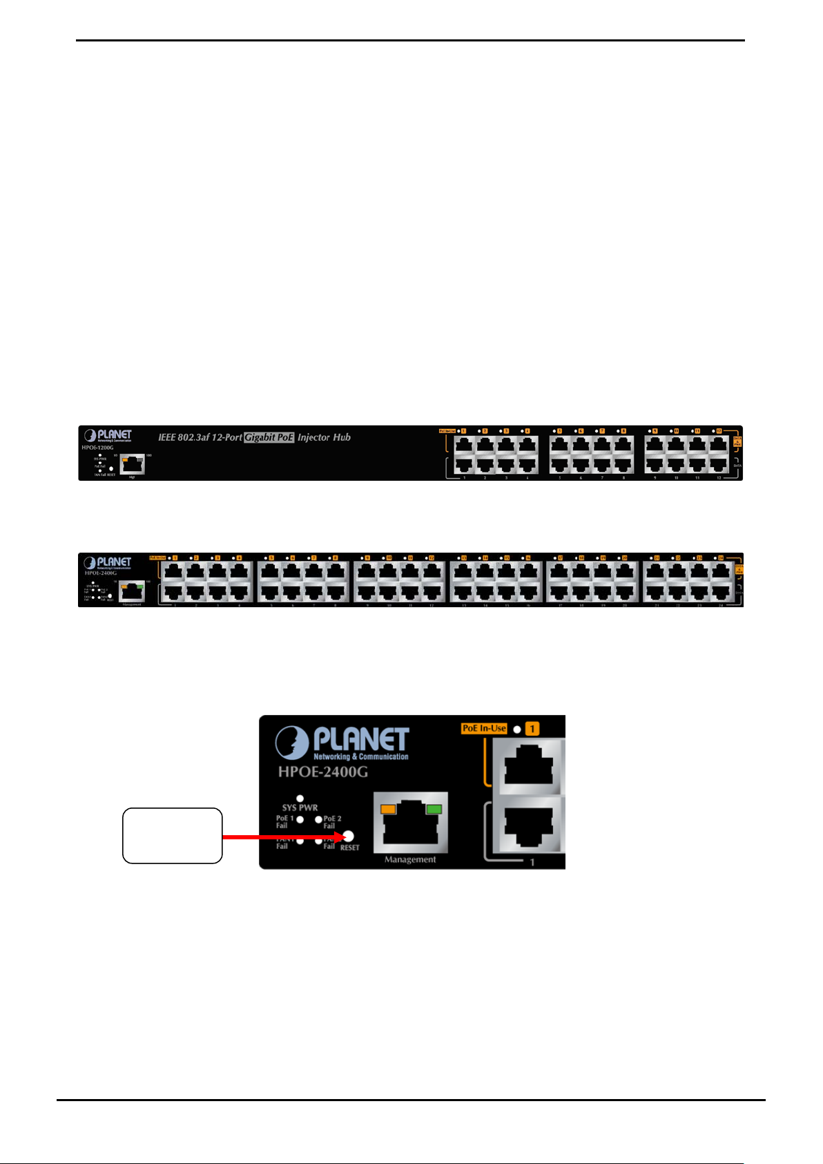
2.1.1 Injector Front Panel
The unit front panel prov ides a simple interfac e monitor ing t he PoE Injector Hub. Figure 2-1-1 & 2-1-2 shows front p anel of
the PoE Injector Hub.
Front Panel of HPOE-1200G
Figure 2-1-1: HPOE-1200G front panel
Front Panel of HPOE-2400G
Figure 2-1-2: HPOE-2400G front panel
■ Reset button
At the left of front pane l, the re set button is de signed for rebo ot the PoE Injector Hub without turn off and on the pow er.
Hardware
Figure 2-1-3: Reset button of PoE Injector Hub
12
Page 13
User’s Manual of HPOE-1200G / HPOE2400G
efore reset PoE Injector
LED
Color
Function
FAN1 Fail
Green
Lights to indicate FAN1 have been stop.
FAN2 Fail
Green
Lights
Power2 Fail
Green
Lights
PoE In-use
Green
Lights to indicate that the port is in use and supplying 48V DC power.
will not work till it is
powered. If your networks should active all the time, please consider using UPS (Uninterrupted Power
from being
The following is the summary table of Reset button funct ion s:
Reset Button Pressed and Released Function
About 1 second Reboot the PoE Injector Hub.
Reset the PoE Injector Hub to Factory Default configuration.
About 8 second
Be sure that you backup the current configuration of PoE Inject or Hub b
Hub; else the entire configuration will be erased when pressing the “RESET” button.
The PoE Injector Hub will reboot and load the default IP
settings as below.
2.1.2 LED Indicators
The front panel LEDs indicates instant status of system power, Management port Link/Active and PoE port links, helps
administrator to monitor and tr oubleshoot when needed.
to indicate FAN2 have been stop. (Only for HPOE-2400G)
Power1 Fail Green Lights to indicate one of power supply 1 has failure.
to indicate one of power supply 2 has failure. (Only for HPOE-2400G)
Power Green Lights to indicate power on.
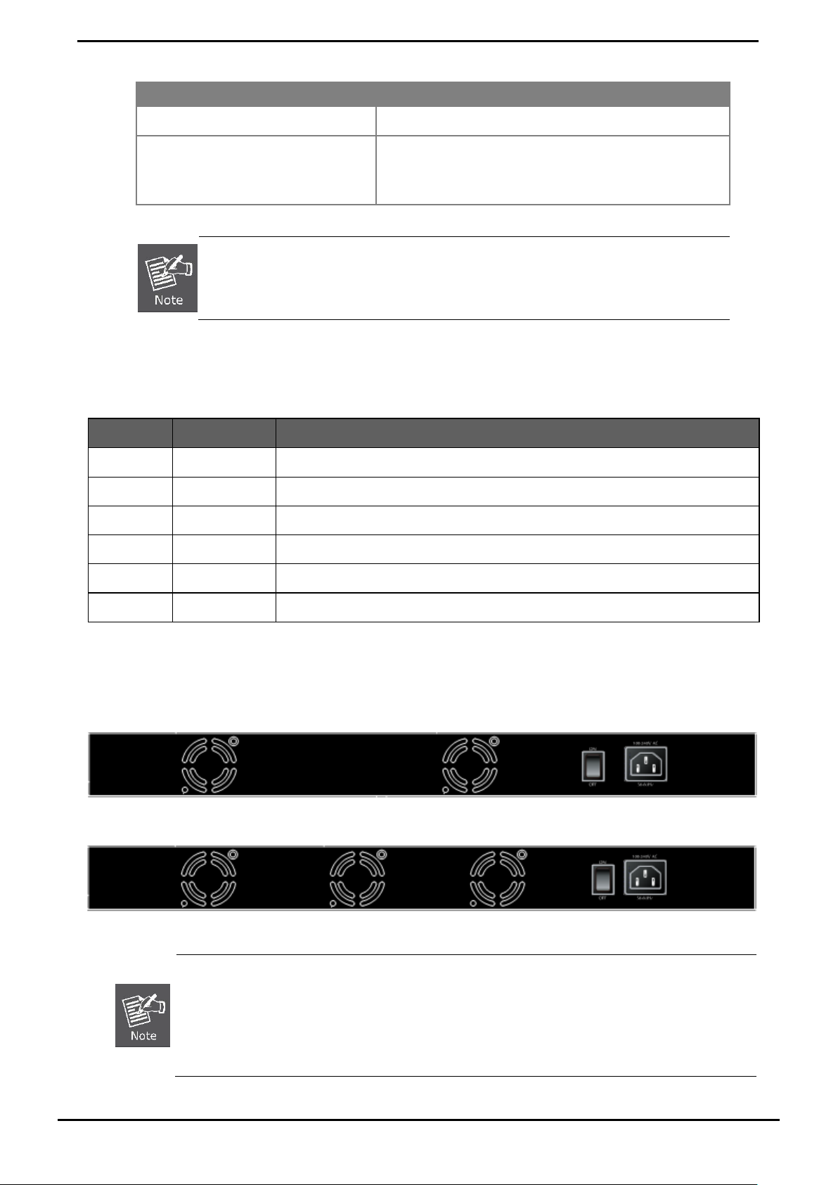
2.1.3 Injector Rear Panel
The rear panel of the PoE Injector Hub indicates an AC inlet power socket, which accepts input power from 100 to 240V
AC, 50/60Hz. Figure 2-1-4 & 2-1-5 shows rear panel of the PoE Injector Hub.
Figure 2-1-4: HPOE-1200G Rear Panel
Figure 2-1-5: HPOE-2400G Rear Panel
The PoE Injector Hub is a power-required device, it means, PoE Injector Hub
Supply) for your device. It will prevent you from network data loss or network downtime.
In some area, installing a surge suppression device may also help to protect your device
damaged by unregulated surge or current to the PoE Injector Hub or the power adapter.
13
Page 14
User’s Manual of HPOE-1200G / HPOE2400G
2.2 Installing the PoE Injector Hub
This section describes how to install your PoE Injector Hub an d make connection s to the PoE Inject or Hub. Please read the
following topics and perfor m th e pro cedures in th e or der bei ng pr esen ted. PLANET PoE Inj ector H ub do not need software
configuration. To install the PoE Injector Hub on a desktop or shelf, simply complete the following steps.
2.2.1 Desktop Installation
To install a PoE Injector Hub on a desktop or shelf, simply complete the following steps:
Step1: Attach the rubber feet to the recessed areas on the bottom of the PoE Injector Hub.
Step2: Place the PoE Injector Hub on a desktop or shelf near an AC power source.
Step3: Keep enough ventilation space between the PoE Injector Hub and the surrounding objects.
When choosing a location, please keep in mind the environmental restrictions discussed in Chapter
1, Section 5, in Specification.
Step4: Connect your PoE Injector Hub to network 802.3at / 802.3af powered devices (PD) and Switch.
A. Connect one end of a standard netw ork cable to t he upper stack 10/100/1000 RJ-45 ports on the front o f the PoE
Injector Hub.
B. Connect the other end of the cable to the 802.3at / 802.3af powered devices (PD) such as IP phone, wireless
access point, IP camera, splitter, or switch etc.
C. Connect the one end of a standard n etw ork cable t o the r elati ve lower stac k 10/100/1000 RJ-45 port on t he fron t
of the PoE Injector Hub.
D. Connect the other end of the cable to the port of Switch.
Connects to the PoE Injector Hub require UTP Category 5e/6 network cabling with RJ-45 tips. For
more information, please see the Cabling Specification in Appendix A.
Step5: Supply power to the PoE Injector Hub.
A. Connect one end of the power cable to the PoE Injector Hub.
B. Connect the power plug of the power cable to a standard wall outlet.
When the PoE Injector Hub receives power, the Power LED should remain solid Green.
2.2.2 Rack Mounting
To install the PoE Injector Hub in a 19-inch standard rack, follow the instructions described below.
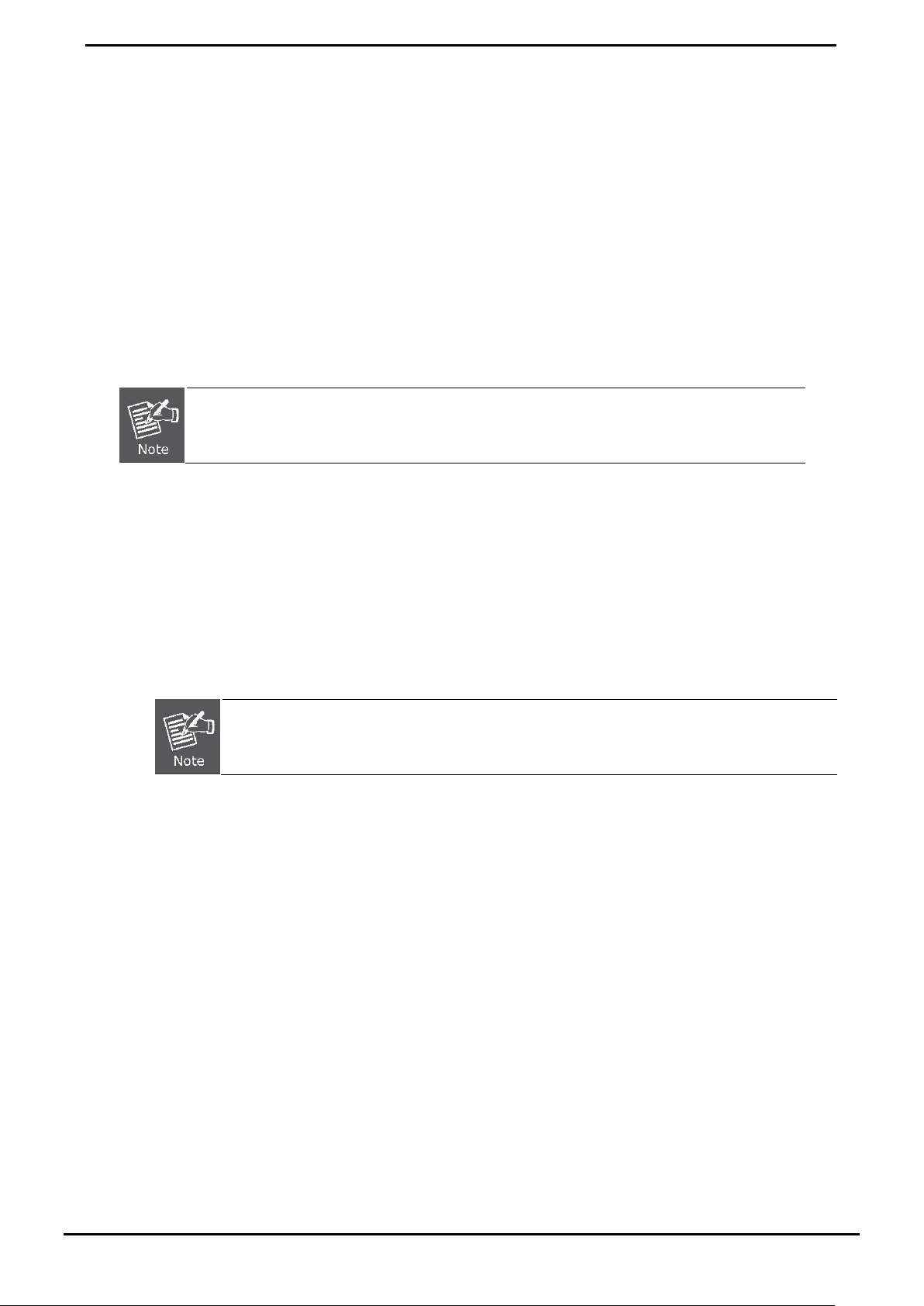
Step1: Place your PoE Injector Hub on a hard flat surface, with the front panel positioned towards your front side.
Step2: Attach a rack-mount bracket to each side of the PoE Injector Hub with supplied screws attached to the package.
Figure 2-2-1 shows how to attach brackets to one side of the PoE Injector Hub.
14
Page 15
User’s Manual of HPOE-1200G / HPOE2400G
You must use the screws supplied with the mounting brackets. Damage caused to the parts by
Figure 2-2-1: Brackets attaching to the PoE Injector Hub
using incorrect screws would invalidate the warranty.
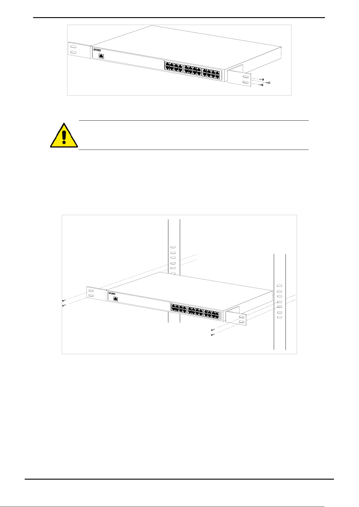
Step3: Secure the brackets tightly.
Step4: Follow the same steps to attach the second bracket to the opposite side.
Step5: After the brackets are attached to the Injector, use suitable screws to securely attach the brackets to the rack, as
shown in Figure 2-2-2.
Figure 2-2-2: Mounting the PoE Injector Hub in a Rack
Step6: Proceeds with the steps 4 and steps 5 of session 2.2.1 Desktop Installation to connect the network cabling and
supply power to your PoE Injector Hub.
15
Page 16
User’s Manual of HPOE-1200G / HPOE2400G
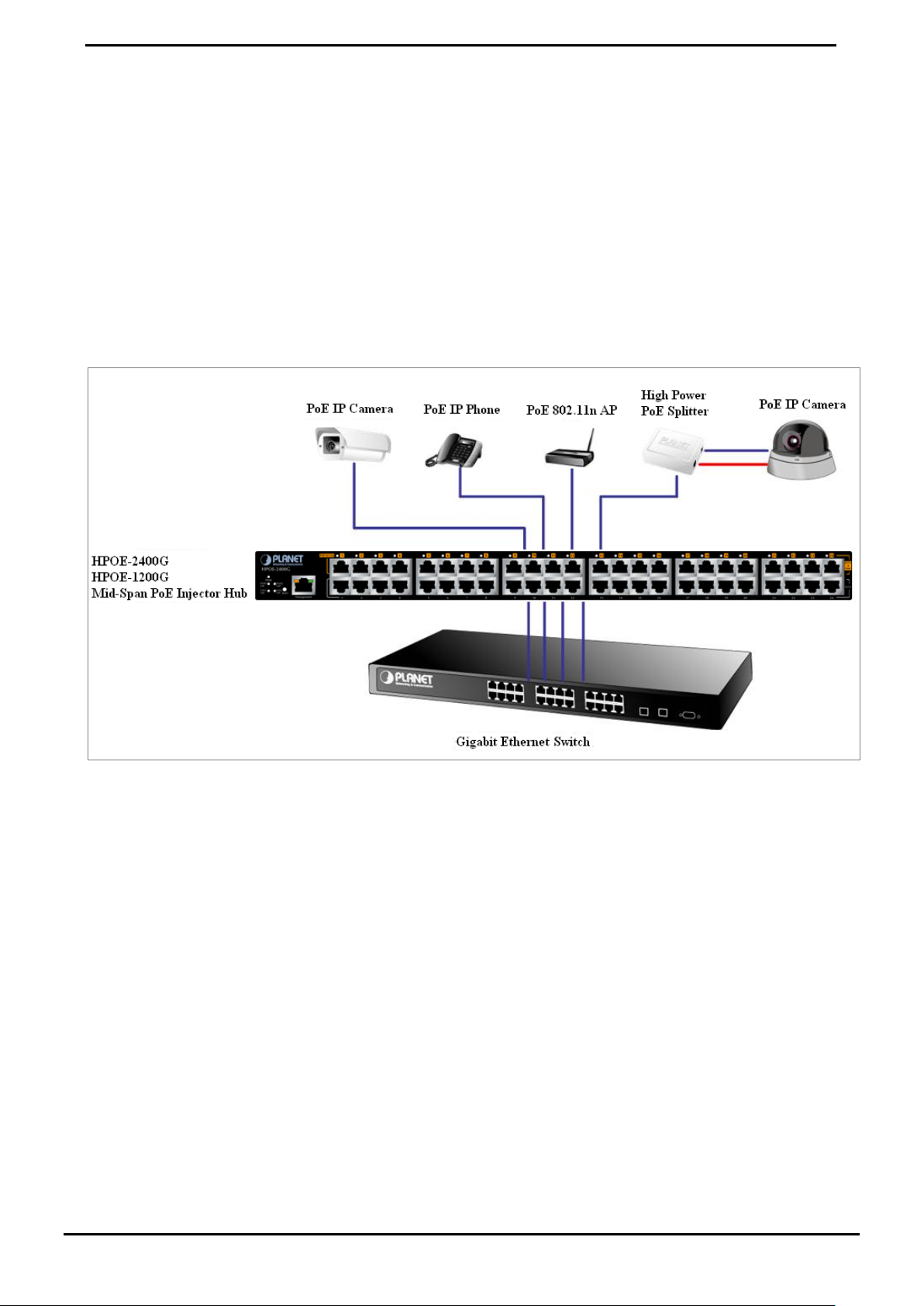
2.2.3 Network Application Installation
The PoE Injector Hub is not equipment with data switching function between data ports. To inject PoE power and transmit
data packet s to PD s, th e PoE Injec tor H ub i s us ual ly link to an Ethernet switch. Typically, the Mid-Sp an Inject or is i nstalled
between regular Ethernet switch and PDs, and mostly it is located close to the Ethernet switch side.
To install a PoE Injector Hub on a network environment, simply complete the following steps:
Step1: Power on the PoE Injector Hub and connect the RJ-45 cable from the “Data” port to the Ethernet switch port.
Step2: Connect the RJ-45 cable from the “Data + Power” ports to the PDs, such as VoIP phone, IP camera.
Step3: Check the link stat us on both P D and Ethern et switch, once the In jector start t o deliver 52V power ov er RJ-45 cables
to PDs, the PoE In-Use LED of the PoE Injector Hub lights.
Figure 2-2-3: Network applicat ion inst al lati on
The PoE Injector Hub supports Data passive mode, that is, even the PoE Injector Hub is manual power off, the data
between “DATA” port and “DATA & PWR” port can still be transmitted without data loss.
16
Page 17

2.2.4 Power over Ethernet Powered Device
Museum, Sightseeing, Airport, Hotel, Campus, Factory, Warehouse can install the
V DC over the Ethernet cable into 5/9/12V DC
ment from restrictions due to power outlet
the costs for additional AC wiring and reduces the
Voice over IP phones
Enterprise can install POE VoIP Phone, ATA and other Ethernet/non-Ethernet
3~5 Watts
6~12 Watts
10~12 Watts
3~12 Watts
end-devices to the centr al w here UPS is installed for u n-int errupt power system and
Wireless LAN Access Points
Access Point any where with no hesitation
IP Surveillance
Enterprise, Museum, C ampus, Hospit al, Bank, can install IP C amera without limits of
install location – no need electrician to install AC sockets.
PoE Splitter
PoE Splitter split the PoE 52V DC over the Ethernet cable into 5/9/12V DC power
output. It frees the device d eployment fro m restr iction s due to power o utlet l ocations,
which eliminate the costs for additional AC wiring and reduces the installation time.
User’s Manual of HPOE-1200G / HPOE2400G
power control system.
3~25 Watts
High Power PoE Splitter
High PoE Splitter split the PoE 52
power output. It frees the device deploy
locations, which eliminate
installation time.
17
Page 18

User’s Manual of HPOE-1200G / HPOE2400G
3 MANAGEMENT
This chapter describes how to manage the PoE Injecto r Hub. Topics inclu de:
- Overview
- Management method
- Logging on to the PoE injector Hub
3.1 Overview
The PoE injector Hub provides a user-friendly, Web interface. Using this interface, you can perform various device
configuration and management activities, including:
System
Power over Ethernet
Tools
3.2 Requirements
■ Network cables.
Use standard network (UTP) cables with RJ45 connectors.
■ Subscriber PC installed with Ethernet NIC (Network Card)
■ Workstations of subscribers running Windows 98/ME, NT4.0, 2000/2003/XP, MAC OS X or later, Linux , UNIX or
other platform compatible with T CP /IP protoco ls.
■ Above PC installed with WEB Browser and JAVA runtime environment Plug-in
It is recommended to use Internet Explore 7.0 or above to access the PoE Injector Hub.
18
Page 19

User’s Manual of HPOE-1200G / HPOE2400G
3.3 Management Method
User can manage the PoE injector Hub by Web Management via a network connection.
3.3.1 Web Management
The PoE Injector Hub can be c onfig ured t hro ugh an Eth ernet conn ect ion, the factory default IP address is 192.168.0.100
with subnet mask 255.255.255.0, so please make sure the m anager P C must be set o n the same IP subnet address. For
example, if POE Injector H ub IP addr ess is kee ps factory def ault then y our manager PC s hould b e set 192.168.0.x (where
x is a number between 1 a nd 254, ex cept 100) with subnet mask 255.255.255.0.
1. Use Internet Explorer 7.0 or abov e Web browser. Ent er IP addr es s http://192.168.0.100 to access the Web interface.
Figure 3-1-1: Web Management over Ethernet
2. When the following login screen appears, please enter the default username "admin" and password “admin” to login
the main screen of PoE Injector Hub. The login screen in Figure 3-1-2 appears.
Default IP Address: 192.168.0.100
Default Account: admin
Default Password: admin
Figure 3-1-2: PoE Injector Hub Web Login screen
19
Page 20

User’s Manual of HPOE-1200G / HPOE2400G
two LAN cards or abov e in th e sam e admi nistrat or PC, c hoose differ ent LAN card by us e the
1. For security reason, please change and memorize the new password after this first setup.
2. Only accept command in lowercase letter under Web interface.
3.3.2 PLANET Smart Discovery Utility
For easily list the PoE Injector Hub in your Ethernet environment, the Planet Smart Discovery Utility from user’s manual
CD-ROM is an ideal solution.
The following install instructions guiding you for run the Planet Smart Discovery Utility.
Deposit the Planet Smart Discovery Utility in administrator PC.
Run this utility and the following screen appears.
Figure 3-1-3: Planet Smart Discovery Utility Screen
If there are
“Select Adapter” tool.
20
Page 21

User’s Manual of HPOE-1200G / HPOE2400G
1. Press “Refresh” button for list current connected devices in the discovery list, the screen is shown as follow.
Figure 3-1-4: Planet Smart Discovery Utility Screen
This utility show all necessary informat ion from the devices, s uch as MA C Address, Devic e Name, fir mware version, D evice
IP Subnet address, also can assign new password, IP Subnet address and description for the devices.
After setup completed, press “Update Device”, “Update Multi” or “Update All” button to take affect. The mea nings of 3
buttons above are shown as below:
Update Device: use current set tin g on one singl e devi ce.
Update Multi: use current setting on choo se multi -devices.
Update All: use current setting on whole devices in the list.
The same functions mentioned above also can be finding in “Option” tools bar.
To click the “Control Packet Force Broadcast” function, it can allow assign new setting value to the PoE Injector Hub
under different IP subnet address.
Press “Connect to Device” button then the Web login screen appears in Figure 3-1-2.
Press “Exit” button to shutdown the Planet Smart Discovery Utility.
21
Page 22

User’s Manual of HPOE-1200G / HPOE2400G
4 WEB CONFIGURATION
The PoE Injector Hub provide Web interface for PoE smart funct ion conf ig urati on and make the PoE Injector Hub operate
more effectively - They can be configured through t he Web Brow ser. A network administrator can manage and monitor the
PoE Injector Hub from the local LAN. This section indicates how to configure the PoE Injector Hub to enable its smart
function.
The following screen based on HPOE-2400G, for HPOE-1200G the display will be the same with
HPOE-2400G, except HPOE-1200G has 12 ports only.
4.1 Manin Menu
After a successful login, the main s creen a ppe ar s. The main screen displays the prod uct n a me t he fun cti on me nu, and the
main information in the center. As showed in Figure 4-1-1.
The four items and it description shown as below:
Object Description
System Provides System information of PoE Injector Hub. Explained in section 4.3.
SNMP Provides SNMP Trap informat i on and system information. Explained in section 4.4.
PoE Configuration
Logout Provides Logout function of PoE Injector Hub. Explained in section 4.6.
Provides PoE Management configuration of PoE Injector Hub. Explained in section
4.5.
Figure 4-1-1: Web Main Menu screen
22
Page 23

User’s Manual of HPOE-1200G / HPOE2400G
Object
Description
section 4.3.2
section 4.3.4
4.2 Web Panel
At the top of the Web management page, the active panel displays the link status of management port and PoE port s.
Figure 4-2-1: Web panel screen
Green lit is the network data send or receiver.
Orange lit is the PoE in use.
Red lit is the PoE port not enough po wer to enable. (It will be happene d that if user as signed lo wer powe r
for PD in the Total Limit mode.)
4.3 System
The System function provides system information also allows user to manage PoE Injector Hub system. As showed in
Figure 4-2-2.
Figure 4-2-2: System function menu
The page includes the following information:
• System Information
• IP Configuration
• NTP Configuration
• Password Setting
• Firmware Upgrade
Display the MAC address, Software Version, Hardware Version, IP Address,
Subnet Mask, Gateway and Description. Explained in section 4.3.1.
Allow to change the IP subn et addr e ss of PoE Injector Hub. Explained in
Allow to set system time by manual or synchronize system time from Internet
NTP server. Explained in section 4.3.3.
Allow to change the usernam e and password of PoE Inj ect or Hub. Explained in
Allow to upgrade the latest firmware in the future. Explained in section 4.3.5.
.
.
23
Page 24

User’s Manual of HPOE-1200G / HPOE2400G
4.3.8.
Object
Description
• Configuration Setting
• Factory Default
• System Log
• System Reboot
Allow to backup or restore system configuration. Explained in section 4.3.6.
Allow to reset system to factory default setting. Explained in section 4.3.7.
Allow to enable system log and to record system log. Explained in section
Allow to reboot system. Explained in section 4.3.9.
4.3.1 S ystem In fo rmation
This section display system information of PoE Injector Hu b, the screen in Figure 4-3-1 appears and Table 4-3-1 describes
the system information object of PoE Injector Hub.
• System Name
• MAC Addr e s s
• Software Version
• Hardware Version
• Attain IP Protocol
• IP Address
• Subnet Mask
• Gateway
• Description
• System Date
Figure 4-3-1: System Information Web page screen
Display the PoE Injector Hub model name.
Display the MAC Address of PoE Injector Hub.
Display the current firmware version of PoE Injector Hub.
Display the hardware version of PoE Injector Hub.
Displays the current attain IP protocol of PoE Injector Hub.
Displays the current IP address of PoE Injector Hub.
Displays the current subnet mask address of PoE Injector Hub.
Displays the current gateway address of PoE Injector Hub.
Display the system description of PoE Injector Hub.
Display the current sy ste m dat e of P oE I n jec tor Hub. The system date will correct
if NTP function was enabled and The Hub connected to Internet.
• System UpTime
Table 4-3-1: Descriptions of the System Information Web page screen Objects
Display that when the system started up.
24
Page 25

User’s Manual of HPOE-1200G / HPOE2400G
Object
Description
t receive IP addr ess fr om DHC P serv er the n user still can c onnect to t he IP a ddre ss
before change to DHCP client mode, or user can use Smart Discovery Utility to find out what is IP address
4.3.2 IP Configuration
This section provides the IP Configuration of PoE Injector Hub, the sc reen in Figure 4-3-2 appears and Table 4-3-2
describes the IP Configuration object of PoE Injector Hub.
Figure 4-3-2: IP Configuration Web page screen
• DHCP Client
• IP Address
• Subnet Mask
• Default Gateway
• Description
• Apply
• Reset
If PoE Injector Hub didn’
set in the PoE Injector Hub currently.
Allow disable or enable the DHCP Client function of PoE Injector Hub.
Allow input new IP Address of PoE Injector Hub.
Allow input new Subnet Mask Address of PoE Injector Hub.
Allow input new Default Gateway Address of PoE Injector Hub.
Allow input new system description of PoE Injector Hub, the maximum length is
20 characters.
Press this button to take effect.
Press this button for resets not apply IP Configuration to default mode.
Table 4-3-2: Descriptions of the IP Configuration Web page screen Objects
25
Page 26

User’s Manual of HPOE-1200G / HPOE2400G
4.3.3 NTP Configuration
This section provides the NTP Configuration of PoE Injector Hub, the screen in Figure 4-3-3 appears and Table 4-3-3
describes the NTP Configuration object of PoE Injector Hub.
Figure4-3-3: NTP Configuration Web page screen
Object Description
• Current Time
• Enable NTP client update
• Time Zone Select
• NTP Server
• Apply
• Refresh
Table 4-3-3: Descriptions of the NTP Configuration Web page scre en Objects
Allow input current time information of PoE Injector Hub.
Allow disable or enable time update from NTP server of PoE Injector Hub.
Allow select the time zone according to current location of PoE Injector Hub.
Allow choose one list NTP server or assign one NTP server IP address manually
for PoE Injector Hub.
Press this button to take effect.
Press this button to refresh current Web page.
26
Page 27

User’s Manual of HPOE-1200G / HPOE2400G
4.3.4 Password Setting
This section provide the Password Setting of PoE Injector Hub, the screen in Figure 4-3-4 appears and Table 4-3-4
describes the Password Setting object of PoE Injector Hub.
Figure 4-3-4: Password Setting Web page screen
Object Description
• User Name
• Old Password
• New Password
• Confirmed Password
• Apply
• Reset
Table 4-3-4: Descriptions of the Password Setting Web page screen Objects
1. For security reason, please change and memorize the new password after this first setup.
2. The maximum length is 15 characters.
Allow input current User Name of PoE Injector Hub.
Allow input current Password of PoE Injector Hub.
Allow input new Password of PoE Injector Hub.
Allow input new Password again for confirm of PoE Injector Hub.
Press this button to take effect.
Press this button for resets not apply setting to default mode.
27
Page 28

User’s Manual of HPOE-1200G / HPOE2400G
30 seconds to complete and system will reboot automatically.
4.3.5 Firmware Upgrade
This section provides the firmware upgrade of PoE Inject or Hub, the screen in Figure 4-3-5 appears.
Figure 4-3-5: Firmware Upgrade Web page screen
Please press “Browse” to locate the latest firmware of PoE Injector Hub that deposit in your PC. The screen in Figure
4-3-6 appears.
Figure 4-3-6: Firmware Upgrade Web page screen
Press “Upgrade” to start the firmw are upgr ade pro ces s, the screen in Figure 4-3-7 appears.
Figure 4-3-7: Firmware Upgrade Web page screen
1. The firmware upgrade process needs
After PoE Injector Hub power on complete, then y ou can use latest firmware.
2. Please do not power off the PoE Injector Hub during firmware upgrade process
28
Page 29

User’s Manual of HPOE-1200G / HPOE2400G
Object
Description
4.3.6 Configuration Setting
This function allows output the current PoE Injector Hub configuration as a file, and upload it to other PoE injector Hub for
quick multi-devices setting. The description of the proce dure and screens in follow ing a ppe ars. T he screen in Figure 4-3-8
appears and Table 4-3-5 describes the Configuration Setting object of PoE Injector Hub.
Figure 4-3-8: Configuration Backup screen
• Save Settings to File
• Load Settings form File
• Browse…
• Upload
Table 4-3-5: Descriptions of the Configuration Setting Web page screen Objects
■ Configur ation Download
All current configurations (except IP Configuration) will output as a configuration file once the “Save” button is pressed,
save the current configuration in manager workstation and the screen in Figure 4-3-9 to Figure 4-3-11 appears.
Allow to save system conf iguration to a f ile and dow nload to manage r workstation.
Allow to restore system configuration to PoE Injector Hub.
Allow to specify the system configuration file locate path.
Upload system configuration file to PoE Injector Hub.
Figure 4-3-9: File Download screen
29
Page 30

User’s Manual of HPOE-1200G / HPOE2400G
■ Configur ation Upload
Figure 4-3-10: File save screen
Figure 4-3-11: File save screen
Click the “Browse” button of the Configuration Setting Web page, the system would pop up the file selection screen to
choose saved configuration. The screen in Figure 4-3-12 appears.
30
Page 31

User’s Manual of HPOE-1200G / HPOE2400G
Figure 4-3-12: Windows file selection screen
Select on the configuration file then click “Upload”. After system had done to upload, screen in Figure 4-3-13 appears.
Figure 4-3-13: Configuration uploa d finis hed screen
When configuration had done to upload please re-login in system again.
Figure 4-3-14: System Login screen
31
Page 32

User’s Manual of HPOE-1200G / HPOE2400G
4.3.7 Factory Default
This section provides reset the PoE Injector Hub to factory default mode, the screen appears in Figure 4-3-15.
Figure 4-3-15: Factory Default Web page screen
Please press “Reset” button to take effect and the “Do you really want to reset the current settings to default?” pop
window appears, please press “OK” button to continue the factory default process. The screen appears in Figure 4-3-16.
Figure 4-3-16: Factory Default Web page screen
Then the reboot screen appears in Figure 4-3-17 and press “Reboot” button for reboot the PoE Injector Hub.
Figure 4-3-17: Factory Default Web page screen
32
Page 33

User’s Manual of HPOE-1200G / HPOE2400G
The pop window with “Wait for 30 seconds while rebooting” appears, the screen in Figure 4-3-18 appears.
Figure 4-3-18: Factory Default Web page screen
After 30 second press “OK” button then the main menu Web page screen appears in Figure4-3-19.
Figure 4-3-19: Main Web page screen
33
Page 34

User’s Manual of HPOE-1200G / HPOE2400G
Object
Description
4.3.8 System Log
This section provides the system log setting and information display of PoE Injector Hub, the screen in Figure 4-3-20
appears and Table 4-3-6 describes the system log setting object of PoE Injector Hub.
• Enable Log
• Enable Remote Log
• Log Server IP Address
• Apply
• Refresh
• Clear
Figure 4-3-20: System Log Web page screen
Provide disable or enable the system log function of PoE Injector Hub.
Allow to send system log to remote log server.
Allow to set IP address of remote log server.
Press this button to take effect.
Press this button to refresh current Web page.
Press this button to clear system log information.
Table 4-3-6: Descriptions of the System Log Web page screen Objects
34
Page 35

User’s Manual of HPOE-1200G / HPOE2400G
4.3.9 System Reboot
This section provides the system reboot function of PoE Injector Hub, the screen in Figure 4-3-21 appears.
Figure 4-3-21: System Reboot Web page screen
Press “Reboot” button to reboot the PoE Injector Hub, the screen in Figure 4-3-22 appears
Figure 4-3-22: System Reboot Web page screen
Wait for 30 seconds for complete the reboot process of PoE Injector Hub.
4.3.10 Logout
This section provides logout function of PoE Injector Hub, the scree n in Figure 4-3-23 appears.
Figure 4-3-23: Logout Web page screen
Press “Logout” button then the pop window with re-login request appears, the screen in Figure 4-3-24 appears.
Figure 4-3-24: Logout Web page screen
35
Page 36

User’s Manual of HPOE-1200G / HPOE2400G
Please i nput the passw ord for enter s into Web main menu screen of PoE Injector Hub, t he screen in Figure 4-3-25 appears.
Figure 4-3-25: Main Web page screen
36
Page 37

User’s Manual of HPOE-1200G / HPOE2400G
Explained in section 4.4.1
4.4 SNMP
The Simple Network Management Protocol (SNMP) is an application layer protocol that facilitates the exchange of
management information between network devices. It is part of the Transmission Control Protocol/Internet Protocol
(TCP/IP) protocol suit. SNMP enables network administrations to manage network performance, find and solve network
problems, and plan for network growth.
The SNMP provides SNMP Management and SNMP Trap as shown in Figure 4-4-1.
Figure 4-4-1: SNMP function menu
The page includes the following information:
Object Description
Allow to enable or disable SNMP Agent and Trap Receiver function. It provides
• SNMP management
user to manage system information and SNMP Trap destination IP address.
.
Table 4-4-1: Descriptions of the System Log Web page screen Objects
4.4.1 SNMP Management
This section provides SNM P setting of PoE Inje ctor Hub, the screen in Figure 4-4-2 appear s and Table 4-4-2 describes the
SNMP object of PoE Injector Hub.
Figure 4-4-2: SNMP Web page screen
37
Page 38

User’s Manual of HPOE-1200G / HPOE2400G
Object
Description
• SNMP Agent
• SNMP Read Community
• SNMP Write Community
• System Name
• System Location
• Contact
• Description
• SNMP Trap
• SNMP Trap Destination
Table 4-4-2: Descriptions of the SNMP Web page screen Objects
Provide disable or enable the SNMP Agent function of PoE Injector Hub.
Allow input characters for SNMP Read Community of P oE I njec tor Hub, the
maximum length is 30 characters.
Allow input characters for SNMP Write Community of PoE Injector Hub, the
maximum length is 30 characters.
Allow input characters for System Na me of PoE Injector Hub, the maximum length
is 30 characters.
Allow input characters for System Location of PoE Injector Hub, the maximum
length is 30 characters.
Allow input characters for contact of PoE Injector Hub, the maximum length is 30
characters.
Allow input characters for description o f P oE Injector Hub, the maximum length is
30 characters.
Allow to enable or disable SNMP Trap function.
Allow to send SNMP trap to an assigned workstation.
38
Page 39

User’s Manual of HPOE-1200G / HPOE2400G
4.5.1
4.5 Power over Ethernet
Power Management:
In a power over Ethernet system, operating power is applied from a power source (PSU-power supply unit) over the LAN
infrastructure to powered devices (PDs), which are connected to ports. Under some conditions, the total output power
required by PDs can exceed the maximum available power prov ided by th e PSU . The sy stem may a prior be p laned w ith a
PSU capable of supp lying less power than the tot al pot ential p ower consum ption of a ll the P oE port s in the system. In order
to maintain the majority of ports active, power management is implemented.
The PSU input power consumption is monitored by measuring v oltage a nd cur r ent .T he in put power consumption is equal
to the system’s aggregated pow er consumption .T he power mana gement conc ept allows al l ports to be active and activat es
additional ports, as long as the aggregated power of the system is lower than the power level at which additional PDs
cannot be connected .When this value is exceeded, ports will be deactivated, according to user-defined priorities. The
power budget is managed according to the following user-definable parameters: maximum available power, ports priority,
maximum allowable power per port.
The Power over Ethernet provides PoE Configuration and PoE Schedule as shown in Figure 4-5-1.
Figure 4-5-1: Power over Ethernet function menu
The page includes the following information:
Object Description
• PoE Configuration
• PoE Schedule
Table 4-5-1: Descriptions of the System Log Web page screen Objects
Allow to centralized management PoE power for PDs. Explained in section
Allow to centralized management PoE power providi ng sch e dule. Explai ned in
section 4.5.2.
39
Page 40

User’s Manual of HPOE-1200G / HPOE2400G
Object
Description
Enabled to prevent syste m to o hot to damage. When POE unit temperature rise an d
4.5.1 PoE Configuration
This section provides PoE (Power over Ethernet) Configuration and PoE output status of PoE Injector Hub, scr een in
Figure 4-5-2 appears and Table 4-5-2 describes the PoE Configuration object of PoE I njector Hub.
• System POE Admin Mode
• Power Supply
• POE Temperature Unit 1
• POE Temperature Unit 2
• Power l imit mode
Figure 4-5-2: PoE Configuration Web page screen
Allows user to disable PoE function.
Display PoE power supply status.
Display the current operating temperature of PoE chip unit 1.
Display the current operating temperature of PoE chip unit 2.
Allows user to configure power limit mode. It can be choose :
No Limit: Deliver unlimited PoE power budget.
Port Priority: According to port priority setting and device class to deliver PoE
power.
Total Limit: According to port power limit setting to deliver PoE power. The default
port power limit setting is 0 watts when you change to this mode.
Consumption: According to real device power consumption to deliver PoE power.
As system default setting is on this mode.
over Temperature Threshold value, PoE power budget will be reduced 10 watts
when the temperature raised 3 Degree C each time, and PoE power budget will
• Over Temperature
Protection
going down 30 watts maximum.
For example, 460 watts is default PoE power budget and Temperature Threshold is
50 Degree C. PoE temperature raise is going to cause PoE Power budget changing
as follow.
40
Page 41

User’s Manual of HPOE-1200G / HPOE2400G
Allows user to set a temperature for alerting system log and syslog once PoE unit
PoE Unit Temperature PoE Power Budget
50 460 watts
51 450 watts
54 440 watts
• Temperature Threshold
• Power Allocation
• PoE Function
• Power Mode
• Priority
• Device Class
57 430 watts
temperature over temperature threshold.
Also, the threshold offers a standard for Over Temperature protection to function.
Display current total pow er consu mpti on stat us.
Allows user to disable or enable per port PoE function.
Allows user to select IEEE 802.3at / IEEE 802.3af mode for port. Please be noticed
that PoE device may not be offered enough power if the PoE device is supported
IEEE 802.3at but user select IEEE 802.3af mode, because IEEE 802.3af mode is
delivering 15.4 watts maximu m only , and als o syst em reser ve 15. 4 watt s only f or the
PoE device if it is supported Class4 level.
Allows user to set PoE port priority. There are 3 level could be configured, they are
Critical, High and Low. The Critical is highest priority and Low is lowest priority.
This function is worked under Priority power limit mode only.
Display PoE class level. The IEEE 802.3af standard offers PoE class level from 1 to
3 and IEEE 802.3at standard offers the class from 1 to 4.
• Current Used [mA]
• Powered Used [W]
• Power Limit [W]
• Apply
• Refresh
Table 4-5-2: Descriptions of the Poe Configuration Web pag e screen Objects
Display PoE device current.
Display PoE device power consumption.
Allows user to custom power for port. This function is worked under Total Limit
power limit mode. This function also related to Power Mode. If Power mode is
802.3af then user can allocate to 15.4 watts maximum, otherwise user can allocate
to 30 watts.
Press this button to take effect.
Press this button to refresh current Web page.
41
Page 42

User’s Manual of HPOE-1200G / HPOE2400G
Range of maximum power used by the
Range of maximum power used by the
0
Default
0.44 to 15.4 Watts
0.44 to 32 Watts
2
Optional
4 to 7 Watts
4 to 7 Watts
3
Optional
7 to 15.4 Watts
7 to 15.4 Watts
PD Classifications
A PD may be classified by the PSE based on the classification information provided by the PD. The intent of PD
classification i s to provi de information a bout the max imum power r equired by the PD during operat ion. Class 0 is the default
for PDs. However, to improve power management at the PSE, the PD may opt to provide a signature for Class 1 to 4.
The PD is classified based on power. The classification of the PD is the maximum power that the PD will draw across all
input voltages and operational mode s.
A PD shall return Class 0 to 4 in accordance with the maximum power draw as specified by Table 4-5-3.
Class Usage
1 Optional 0.44 to 4 Watts 0.44 to 4 Watts
4 Optional Reserved for Future Use 15.4 to 32 Watts
As Table 4-5-4 is a real testing result and it’s not just following IEEE 802.3af / IEEE 802.3at
standard.
IEEE 802.3af PD
IEEE 802.3at PD
Table 4-5-3: Device class
4.5.2 PoE Schedule profile
This section provides user to configure PoE schedule. The “PoE schedule” helps you to enable or disable PoE power
feeding for PoE ports duri ng specified time intervals an d it is a pow erful functio n to help SM B or Enterprise save power and
money.
The PoE Schedule Profile web screens show in Figure 4-5-3 and Table 4-5-4.
42
Page 43

User’s Manual of HPOE-1200G / HPOE2400G
Object
Description
Figure 4-5-3: PoE Configuration Web page screen
The page includes the following information:
• Power Profile
• Function
• Include Port
• button
• button
• button
• button
Table 4-5-4: Descriptions of the PoE Schedule Profile Web page screen Objects
This PoE hub offers totally 24 profiles for user configure PoE schedule.
Allows user to enable or disable the profile.
Provides user to select which PoE port want to apply to the profile.
Go to PoE schedule page.
Display PoE schedule profile information.
Save current configuration.
Refresh WEB page and rest current configuration if user didn’t save it.
43
Page 44

User’s Manual of HPOE-1200G / HPOE2400G
Object
Description
Allows user to configure PoE port open or close for a week.
4.5.3 PoE Schedule
PoE Schedule user can co nfigure a dur ation time for PoE port. A s default v alue is not provide power . Screen in Figure 4-5-4
and Table 4-5-5.
Figure 4-5-4: PoE Schedule Web page screen
The page includes the following information:
• Hour
• Sun. to Sat.
• button
• button
Allows user to configure PoE port open or close from hour 0 to 23.
Sun.: Sunday.
Mon.: Monday.
Tue.: Tuesday.
Wed.: Wednesday.
Thu.: Thursday.
Fri.: Friday.
Sat.: Saturday.
Go to PoE schedule profile page.
Save current configuration.
• button
Table 4-5-5: Descriptions of the PoE Schedule Web page screen Objects
Refresh WEB page and rest current configuration if user didn’t save it.
44
Page 45

User’s Manual of HPOE-1200G / HPOE2400G
4.5.4 PoE Schedule Profile configuration example
Please enable NTP and corre c t P oE hub sy stem tim e first and make sure System PoE Ad m in Mode is enabled, otherwise
you can not confi gure PoE Schedul e profile, you may see a n error message as a screen shot as following. Screen in Figure
4-5-5.
Figure 4-5-5: Error message of PoE Schedule Profile
As default value, all PoE Schedule Profile function are disabled, but you can configure it anyway, and please enable the
function after you finished all configuration.
A situation that enterprise wants PoE port1 to port 12 connects to VoIP phone and provides power for working from AM
08:00 to PM 05:00 of five days a week. PoE port 13 to 20 connects to PoE wirele ss AP and pr ovides pow er for w orking fr om
AM 08:00 to PM 11:00 of five days a week, the oth er PoE port connect t o PoE camera s o it has to be provi ded pow er t o 24
hours.
So, we can use 3 schedule profiles to satisfy the enterprise requirement as following screen shot. Screen in Figure 4-5-6.
Figure 4-5-6: PoE Schedule Profile Configuration
45
Page 46

User’s Manual of HPOE-1200G / HPOE2400G
Press Next >> button to set profile1 of PoE schedule. Screen in Figure 4-5-7.
Figure 4-5-7: PoE Schedule Profile Configuration
Please use mouse to click on t he bloc k about what time you w ant to supply pow er for PoE port, then press Apply button t o
save configuration. Ple ase pre ss << Profile button back to PoE schedule profile configuration page to go on next profile
setting. Screen in Figur e 4-5-8.
Figure 4-5-8: PoE Schedule of VoIP Phone Configuration
Please press Next >> button to set profile2 of PoE schedule. Screen in Figure 4-5-9.
Figure 4-5-9: PoE Schedule Profile Configuration
46
Page 47

User’s Manual of HPOE-1200G / HPOE2400G
Please use mouse to click on t he bloc k about what time y ou want to supply pow er for P oE port, t hen press Apply button to
save configuration. Ple ase pre ss << Profile button back to PoE schedule profile configuration page to go on next profile
setting. Screen in Fig ure 4-5-10.
Figure 4-5-10: PoE Schedule of PoE wireless AP Configuration
Please press Next >> button to set profile2 of PoE schedule. Screen in Figure 4-5-11.
Figure 4-5-11: PoE Schedule Profile Configuration
Please use mouse to click on t he bloc k about what time y ou want to supply pow er for P oE port, t hen press Apply button to
save configuration. Ple ase pre ss << Profile button back to PoE schedule profile configuration page to go on next profile
setting. Screen in Fig ure 4-5-12.
47
Page 48

User’s Manual of HPOE-1200G / HPOE2400G
Figure 4-5-12: PoE Schedule of PoE camera Configuration
User can press Show button to display current PoE schedule setting.
[END]
Figure 4-5-13: PoE Schedule screen
48
Page 49

User’s Manual of HPOE-1200G / HPOE2400G
5. POWER OVER ETHERNET OVERVIEW
What is PoE?
Based on the global standard IEEE 802.3af, PoE is a technology for wired Ethernet, the most widely installed local area
network technology adopted today. PoE allows the electrical power necessary for the operation of each end-device to be
carried by data cables ra ther th an by separat e power cor ds. New network applicat ions, such as IP Camera s, VoIP Phon es,
and Wireless Networking, can help enterprises improve productivity. It minimizes wires that must be used to install the
network for offering lower cost, and less power failures.
IEEE802.3af also called Data Terminal equipment (DTE) power via Media dependent interface (MDI) is an international
standard to define the tra nsmission for power over Ether net. The IEEE 802.3af al so defines two types of source equi pment:
Mid-Span and End-Span.
Mid-Span
Mid-Span device is placed between legacy switch and the powered device. Mid-Span i s tap the un use d wire pairs 4/5 and
7/8 to carry power, the other four is for data transmit.
End-Span
End-Span device is direct connecting with power device. End-Span could also tap the wire 1/2 and 3/6.
PoE system architecture
The specification of PoE typically requires two devices: the Powered Source Equipment (PSE) and the Powered Device
(PD). The PSE is either an E nd -Span or a M id-Span, while the PD is a PoE-enabled terminal, such as IP Phones, Wireless
LAN, etc. Power can be delivered over data pairs or spare pairs of standard CAT-5e cabling.
How power is transferred through the cable
A standard CAT5e Ethernet cable has four twisted pairs, but only two of these are used for 10BASE-T, 100BASE-T and
1000Base-T. The specifi cation allows tw o options for using these c ables for pow er, shown in Figure 5-1-1 and Figure 5-1-2.
The spare pairs are used. Figure 5-1-1 shows the pair on pins 4 and 5 conne cted together a nd formin g the p osit ive supp ly,
and the pair on pins 7 and 8 connected and forming the negative supply. (In fact, a late change to the spec allows either
polarity to be used).
Figure 5-1-1 - Power Supplied over the Spare Pins
49
Page 50

User’s Manual of HPOE-1200G / HPOE2400G
The data pairs are used. S in ce Ether net pairs are transformer coupled at ea ch e nd, it is possible to apply DC pow er to th e
center tap of the i solatio n trans former w ithout ups etting the data tr ansf er. In this mode of ope ration the pa ir o n pin s 3 and 6
and the pair on pins 1 and 2 can be of either polarity.
Figure 5-1-2 - Power Supplied over the Data Pins
When to install PoE?
Consider the following scenarios:
• You're planning to i nstall the latest VoIP Phone syste m to minimiz e cabling bui lding costs w hen your comp any moves int o
new offices next month.
• The company staff has been clamori ng for a wir eless ac ces s point in the picnic area behin d the bui lding so t hey ca n wor k
on their laptops through lunch, but the cost of electrical power to the outside is not affordable.
• Management asks for IP Surveillance Cameras and business access systems throughout the facility, but they would
rather avoid another electrician's payment.
50
Page 51

User’s Manual of HPOE-1200G / HPOE2400G
References:
IEEE Std 802.3af-2003 (Amendment to IEEE Std 802.3-200 2 , includ ing IEE E Std 802. 3ae-2002), 2003 Page(s):0_1-121
White Paper on Power over Ethernet (IEEE802.3af)
http://www.poweroverethernet.com/articles.php?article_id=52
Microsemi /PowerDsine
http://www.microsemi.com/PowerDsine/
Linear Tech
http://www.linear.com/
51
 Loading...