

Page 1

User’s Manual of GSW-4804SF
User's Manual
GSW-4804SF
48-Port 10/100/1000Mbps
with 4-Port Shared SFP
Web Smart Switch
-1-
Page 2

User’s Manual of GSW-4804SF
Trademarks
Copyright © PLANET Technology Corp. 2008.
Contents subject to which revision without prior notice.
PLANET is a registered trademark of PLANET Technology Corp. All other trademarks belong to their respective owners.
Disclaimer
PLANET Technology does not warrant that the hardware will work properly in all environments and applications, and makes no
warranty and representation, either implied or expressed, with respect to the quality, performance, merchantability, or fitness for
a particular purpose.
PLANET has made every effort to ensure that this User's Manual is accurate; PLANET disclaims liability for any inaccuracies or
omissions that may have occurred.
Information in this User's Manual is subject to change without notice and does not represent a commitment on the part of
PLANET. PLANET assumes no responsibility for any inaccuracies that may be contained in this User's Manual. PLANET makes
no commitment to update or keep current the information in this User's Manual, and reserves the right to make improvements to
this User's Manual and/or to the products described in this User's Manual, at any time without notice.
If you find information in this manual that is incorrect, misleading, or incomplete, we would appreciate your comments and
suggestions.
FCC Warning
This equipment has been tested and found to comply with the limits for a Class A digital device, pursuant to Part 15 of the FCC
Rules. These limits are designed to provide reasonable protection against harmful interference when the equipment is operated
in a commercial environment. This equipment generates, uses, and can radiate radio frequency energy and, if not installed and
used in accordance with the Instruction manual, may cause harmful interference to radio communications. Operation of this
equipment in a residential area is likely to cause harmful interference in which case the user will be required to correct the
interference at whose own expense.
CE Mark Warning
This is a Class A product. In a domestic environment, this product may cause radio interference, in which case the user may be
required to take adequate measures.
WEEE Warning
To avoid the potential effects on the environment and human health as a result of the presence of
hazardous substances in electrical and electronic equipment, end users of electrical and electronic
equipment should understand the meaning of the crossed-out wheeled bin symbol. Do not dispose of
WEEE as unsorted municipal waste and have to collect such WEEE separately.
Revision
PLANET 48-Port 10/100/1000Mbps with 4-Port Shared SFP Web Smart Switch User's Manual
FOR MODEL: GSW-4804SF
REVISION: 1.0 (April.2008)
Part No: EM-GSW4804SFv1.0 (2081-A82080-000)
-2-
Page 3

User’s Manual of GSW-4804SF
TABLE OF CONTENTS
1. INTRODUCTION ......................................................................................................................................................................6
1.1 Packet Contents ..............................................................................................................................................................6
1.2 How to Use This Manual..................................................................................................................................................6
1.3 Product Feature ...............................................................................................................................................................7
1.4 Product Specification .......................................................................................................................................................8
2. INSTALLATION.......................................................................................................................................................................10
2.1 Product Description .......................................................................................................................................................10
2.1.1 Product Overview ................................................................................................................................................10
2.1.2 Switch Front Panel ..............................................................................................................................................11
2.1.3 LED Indications ...................................................................................................................................................11
2.1.4 Switch Rear Panel ............................................................................................................................................... 11
2.2 Install the Switch............................................................................................................................................................12
2.2.1 Desktop Installation .............................................................................................................................................12
2.2.2 Rack Mounting.....................................................................................................................................................13
2.2.3 Installing the SFP transceiver ..............................................................................................................................14
3. CONFIGURATION ..................................................................................................................................................................16
3.1 Management Access Overview......................................................................................................................................16
3.2 Administrator Console Access .......................................................................................................................................17
3.3 Reset to Factory Default Mode under Console Interface ...............................................................................................18
3.4 Web Management Access .............................................................................................................................................19
3.5 Management Architecture..............................................................................................................................................20
4. WEB CONFIGURATION .........................................................................................................................................................21
4.1 Home .............................................................................................................................................................................23
4.2 System...........................................................................................................................................................................24
4.2.1 IP Address ...........................................................................................................................................................25
4.2.2 System Information..............................................................................................................................................25
4.2.3 Password.............................................................................................................................................................25
4.2.4 Console ...............................................................................................................................................................26
4.2.5 Management VLAN .............................................................................................................................................26
4.2.6 System Upgrade..................................................................................................................................................26
4.2.7 Parameters Saving ..............................................................................................................................................29
4.2.8 Backup / Recovery ..............................................................................................................................................30
4.2.9 Load Default ........................................................................................................................................................34
4.2.10 Reboot ...............................................................................................................................................................34
4.3 Port Management ..........................................................................................................................................................35
4.3.1 Port Configuration................................................................................................................................................36
4.3.2 Port Statistics.......................................................................................................................................................38
4.3.3 Band Restricting ..................................................................................................................................................40
4.3.4 Cascade Connecting ...........................................................................................................................................41
-3-
Page 4

User’s Manual of GSW-4804SF
4.3.5 Link Test ..............................................................................................................................................................42
4.3.6 Buffer Schedule ...................................................................................................................................................43
4.4 Redundancy...................................................................................................................................................................44
4.5 Security..........................................................................................................................................................................45
4.5.1 ACL......................................................................................................................................................................47
4.5.2 Security Defernce ................................................................................................................................................55
4.5.3 ARP Defernce ......................................................................................................................................................56
4.5.4 VLAN ...................................................................................................................................................................57
4.5.5 MAC Address Binding..........................................................................................................................................66
4.5.6 MAC Address Filtering.........................................................................................................................................68
4.5.7 MAC Address Learning........................................................................................................................................69
4.5.8 MAC Address Aging Time....................................................................................................................................70
4.6 QoS ...............................................................................................................................................................................71
4.6.1 802.1p-Queue Mapping.......................................................................................................................................73
4.6.2 Port Default Priority .............................................................................................................................................74
4.6.3 Queue Management............................................................................................................................................75
4.6.4 Turst Mode...........................................................................................................................................................76
4.7 Multicast ........................................................................................................................................................................77
4.7.1 IGMP Snooping ...................................................................................................................................................80
4.7.2 Static Routing Port...............................................................................................................................................81
4.8 Network Analysis ...........................................................................................................................................................82
4.8.1 Port Analysis........................................................................................................................................................83
4.8.2 Port Mirror............................................................................................................................................................85
4.8.3 QoS Statistics ......................................................................................................................................................86
4.8.4 ARP Attack Log....................................................................................................................................................87
4.9 Network Equipment .......................................................................................................................................................88
4.9.1 Host Security Defense.........................................................................................................................................89
4.9.2 Facility Protection ................................................................................................................................................94
4.9.3 Programme Priority..............................................................................................................................................96
5. SWITCH OPERATION ............................................................................................................................................................98
5.1 Address Table ................................................................................................................................................................98
5.2 Learning.........................................................................................................................................................................98
5.3 Forwarding & Filtering....................................................................................................................................................98
5.4 Store-and-Forward.........................................................................................................................................................98
5.5 Auto-Negotiation ............................................................................................................................................................99
6. TROUBLESHOOTING..........................................................................................................................................................100
APPENDIX A ............................................................................................................................................................................101
A.1 Switch's RJ-45 Pin Assignments .................................................................................................................................101
A.2 RJ-45 cable pin assignment ........................................................................................................................................102
A.3 Available Modules .......................................................................................................................................................103
-4-
Page 5

User’s Manual of GSW-4804SF
APPENDIX B ............................................................................................................................................................................104
802.1Q VLAN Multi-Untagged VLAN setting sample 1 ..........................................................................................104
802.1Q VLAN Multi-Untagged VLAN setting sample 2 ..........................................................................................109
802.1Q VLAN Multi-Untagged VLAN setting sample 3 .......................................................................................... 111
-5-
Page 6

User’s Manual of GSW-4804SF
1. INTRODUCTION
Thank you for purchasing PLANET 48-Port 10/100/1000Mbps with 4-Port shared SFP Web Smart Switch- GSW-4804SF. In the
following section, the term “Switch” means the Switch, i.e. GSW-4804SF; term of “switch” can be any third part switches.
1.1 Packet Contents
Check the contents of your package for following parts:
• GSW-4804SF Web Smart Switch x1
• Quick Installation Guide x1
• User's Manual CD x1
• RS-232 Console Cable x 1
• Power Cord x1
• Rubber Feet x 4
• Two rack-mounting brackets with attachment screws x1
If any of these pieces are missing or damaged, please contact your dealer immediately, if possible, retain the carton including
the original packing material, and use them against to repack the product in case there is a need to return it to us for repair.
1.2 How to Use This Manual
This User Manual is structured as follows:
• Section 2, Installation
The section explains the functions of the Switch and how to physically install the Switch.
• Section 3, Configuration
The section contains the information about the software function of the Switch.
• Section 4, Web Configuration
The section explains how to manage the Switch through Web interface.
• Section 5, Switch Operation
The section explains the switch operation of the Switch.
• Section 6, Troubleshotting
The section contains troubleshooting guide of the Switch.
• Appendex A Networking Connection
The section contains cable information of the Switch.
Appendex B 802.1Q VLAN Multi-Untagged VLAN setting sample
The section contains 802.1Q VLAN setting example of the Switch.
-6-
Page 7

User’s Manual of GSW-4804SF
1.3 Product Feature
¾ Physical Port
48-Port 10/100/1000Base-T RJ-45
4 SFP slots, shared with Port-45, Port-46, Port-47 and Port-48
RS232 Console interface for reset system to factory default mode
¾ Layer 2 Features
Complies with the IEEE 802.3, IEEE 802.3u, IEEE 802.3ab, IEEE 802.3z Gigabit Ethernet standard
Per port supports Auto-negotiation, 10Base-T / 100Base-TX Half-Duplex / Full-Duplex modes and 1000Base-T
Full-Duplex mode.
Auto-MDI/MDI-X detection on each RJ-45 port
Prevents packet loss with back pressure (Half-Duplex) and IEEE 802.3x PAUSE frame flow control (Full-Duplex)
High performance Store and Forward architecture, broadcast storm control, runt/CRC filtering eliminates erroneous
packets to optimize the network bandwidth
16K MAC address table, automatic source address learning and ageing
9K Jumbo frame size
49 Port bas
Support up to 12 Link Aggregation groups, each group for up to maximum 8 port with 16Gbps bandwidth( Full Duplex
Mode)
Port Mirroring to monitor the incoming or outgoing traffic on a particular port
Per port disable / enable, speed duplex mode / Flow control setting
Per port Link Status test
ed VLAN groups / 512 IEEE 802.1Q Tagged based VLAN groups support
¾ Quality of Service
Support for strict priority and Weighted Round Robin (WRR) CoS policies
Support QoS and bandwidth control on each port
¾ Multicast
Support IGMP Snooping V1/V2, up to 256 multicast Groups
Support IGMP Route Port
¾ Security
MAC-Based Access Control List
IP-Based Access Control List (ACL)
TCP/UDP/ICMP Access Control List (ACL)
Security Defense / ARP Defense
Port Security for MAC address binding / filtering / learning / aging time setting
Management
Web-based management
Management VLAN for high security access limit
Web firmware upgradeable
Web configuration backup / recovery
EMI standards comply with FCC, CE class A
-7-
Page 8
1.4 Product Specification
User’s Manual of GSW-4804SF
Product
Hardware Specification
Copper Ports
SFP/mini-GBIC Slots
Switch Architecture
Switch Fabric
Switch Throughput
Address Table
Flow Control
Jumbo Frame
LED
Layer 2 function
GSW-4804SF
48-Port 10/100/1000Mbps with 4-Port Shared SFP Web Smart Switch
48-10 / 100 / 1000Base-T RJ-45 Auto-MDI/MDI-X ports
4 SFP interfaces, shared with Port-45, Port-46, Port-47 and Port-48
Store-and-Forward
96Gbps / non-blocking
71.4Mpps
16K entries
Back pressure for Half-Duplex mode, IEEE 802.3x Pause Frame for Full-Duplex mode
9K
System: Power, SYS (Green)
Per RJ-45 Port: 10/100 LED (Green) and 1000 LED (Orange)
Per SFP interface: 1000 LED (Orange)
Management Interface
Management VLAN
Web firmware upgrade
Configuration backup /
Recovery
Port Configuration
Port Statistics
Link Aggregation
Access Control List
Security Defense
ARP Defense
VLAN
Port Security
QoS
Web Browser interface
Yes
Yes
Yes
Port disable/enable. Auto-negotiation 10/100/1000Mbps full and half duplex mode selection.
Flow Control disable / enable. Bandwidth control on each port.
Display per port’s management status, link status, detail various packet receive information
Supports 12 groups of 8 member port maximum
MAC / IP / TCP/ UDP / ICMP Based Access Control List (ACL)
Yes, worm, RPC Leak, Shake wave, TFTP, Shock wave and Phatbot option
Yes
49 Port Based VLAN groups / 512 IEEE 802.1Q Tagged VLAN groups
MAC address binding / filtering / learning / aging time setting
Quality of Service Queue Management
IGMP Snooping
IGMP Route Port
Port Mirror
Standards Conformance
Regulation Compliance
V1 / V2, up to 256 multicast Groups
Yes
Monitor the incoming or outgoing traffic on a particular port
FCC Part 15 Class A, CE
-8-
Page 9
Standards Compliance
Physical Specifications
User’s Manual of GSW-4804SF
IEEE 802.3 10Base-T
IEEE 802.3u 100Base-TX
IEEE 802.3ab Gigabit 1000Base-T
IEEE 802.3z Gigabit SX/LX
IEEE 802.3x Flow Control and Back pressure
IEEE 802.1p Class of service
IEEE 802.1Q VLAN Tagging
Dimensions
Weight
Power Requirement
Power Consumption /
Dissipation
Environment Specifications
Operating
Storage
430 x 350 x 45mm (W x D x H), 1U height
4.94 kg
100~240V AC, 50-60 Hz
57 Watts / 194 BTU (Maximum)
Temperature: 0°C ~ 50 degree C
Relative Humidity: 20% ~ 85% (non-condensing)
Temperature: -40°C ~ 70 degree C
Relative Humidity: 20% ~ 90% (non-condensing)
-9-
Page 10

User’s Manual of GSW-4804SF
2. INSTALLATION
This section describes the functionalities of the Switch's components and guides how to install it on the desktop or shelf, for
easier management and control of the Switch. Before connecting any network device to the Switch, please read this chapter
completely before continuing.
2.1 Product Description
The PLANET GSW-4804SF is a 48-Port 10/100/1000Mbps with 4-Port shared SFP Web Smart Switch. It boasts a high
performance switch architecture that is capable of providing 96Gbps non-blocking switch fabric and 71.4Mpps wire-speed
throughput. With its four built-in 1000Base-SX / LX SFP interfaces share with port 45 to port 48, the Switch offer incredible
extensibility, flexibility and connectivity between the Core switch and Servers application.
2.1.1 Product Overview
The PLANET GSW-4804SF is a High-Density, Rack-mountable; Layer 2 Web Smart Gigabit Switch. Since Gigabit network
interface had become the basic equipment and requirement of Enterprise and Network Servers, with 96Gbps switching fabric,
the GSW-4804SF can handle extremely large amounts of data in a secure topology linking to a backbone or high capacity
servers. The powerful QoS and Network Security features make GSW-4804SF to meets the needs of effective data traffic
control for ISP and Enterprise, such as VoIP, video streaming and multicast application.
Per Gigabit port with 9K Jumbo frame supported, can handle extremely large amounts of data transmission in a secure topology
linking to a backbone or high-power servers, the four mini-GBIC slots are compatible with 1000Base-SX/LX and WDM SFP
(Small Factor Pluggable) fiber-optic modules. The distance can be extended from 550 meters (Multi-Mode fiber) up to above
10/20/30/40/50/70/120 kilometers (Single-Mode fiber or WDM fiber). They are well suited for using within the enterprise data
centers and distributions.
For efficient management, the GSW-4804SF Web Smart Switch is equipped with Web interfaces. With its built-in Web-based
management, the Switch offers an easy-to-use, platform-independent management and configuration facility. The GSW-4804SF
can be programmed for basic switch management functions such as Port speed configuration, bandwidth control, Link
Aggregation, Access Control List (ACL), VLAN, MAC address binding / filtering / learning / aging time setting. QoS, IGMP
Snooping and Port Mirror function.
-10-
Page 11
User’s Manual of GSW-4804SF
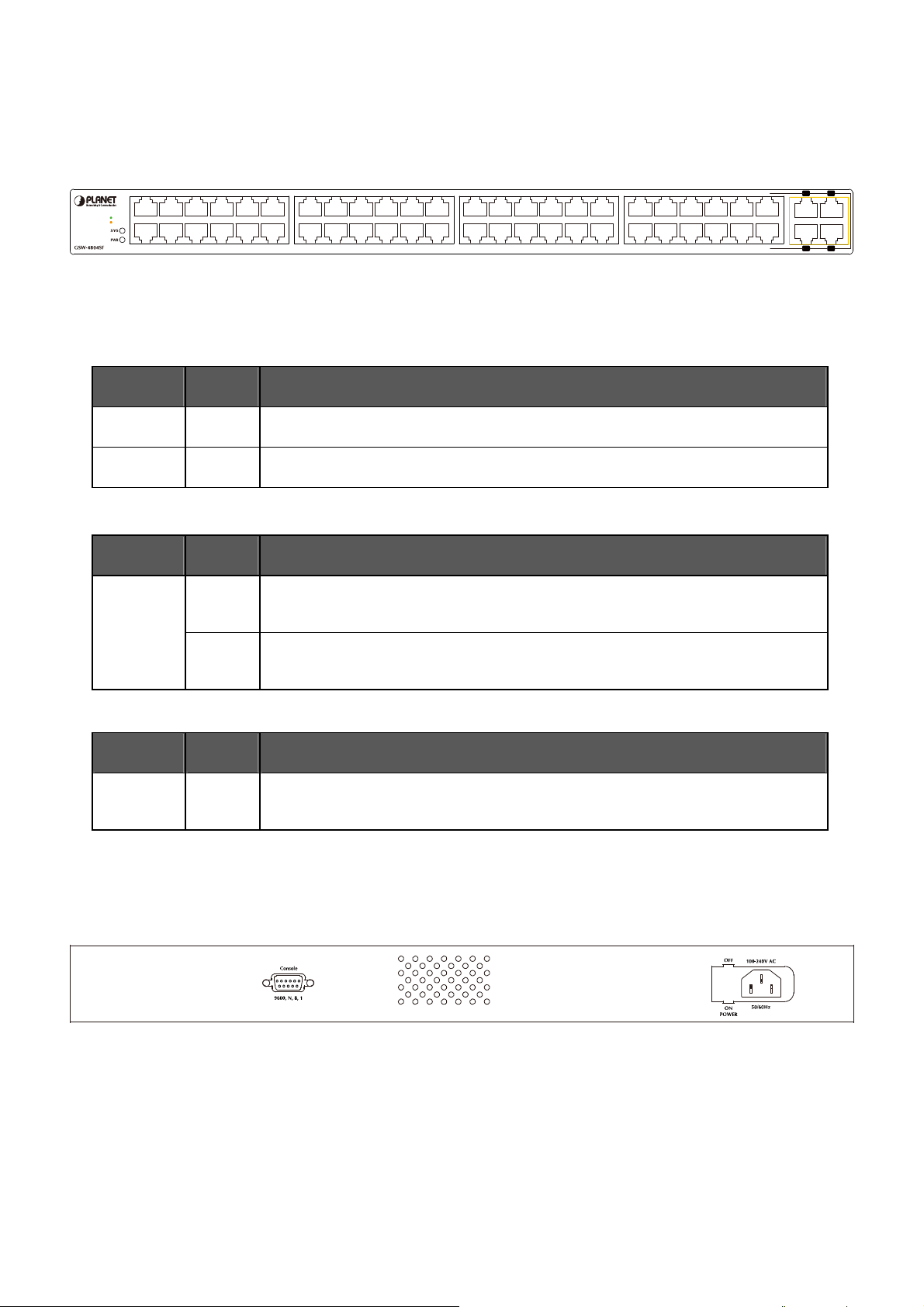
2.1.2 Switch Front Panel
Figure 2-1 shows the front panel of the Switch, it consists of 48 Auto Negotiation 10/100/1000Mbps RJ-45 ports with Auto MDI /
MDI-X feature, four shared Gigabit SFP interfaces with port 45 to port 48 and LED indicators.
4682
10/100
1000
3571
1210
119
16 18 2014
15 17 1913
2422
2321
28 30 3226
27 29 3125
3634
3533
40 42 4438
39 41 4337
4846
4745
4846
4745
Figure 2-1 GSW-4804SF front panel
2.1.3 LED Indications
2.1.3.1 LED Indications
■ System
LED Color Function
PWR
SYS
Green
Green
Lights to indicate that the Switch has power
Lights to indicate that the CPU is operating
■ Per 10/100/1000Base-T RJ-45 port
LED Color Function
Lights to indicate the port is running in 1000Mbps speed
Orange
LNK/ACT
(Dual Color)
Blink: indicate that the switch is actively sending or receiving data over that port
Lights: indicate that the port is operating at 10Mbps or 100Mbps
Green
Blink: indicate that the switch is actively sending or receiving data over that port
■ Per SFP interfaces ( Share with 10/100/1000Base-T Port-45, Port-46, Port-47 and Port-48)
LED Color Function
Lights to indicate the port is running in 1000Mbps speed
LNK/ACT
Orange
Blink: indicate that the switch is actively sending or receiving data over that port
2.1.4 Switch Rear Panel
Figure 2-2 shows the rear panel of the Switch, the rear panel indicates an AC inlet power socket that accept input power from
100-240V AC, 50/60Hz and one ON / OFF switch, also one RS-232 console port for reset system to factory default mode.
Figure 2-2 GSW-4804SF real panel
Power Notice:
1. The device is a power-required device, it means, it will not work till it is powered. If your networks should active all the
time, please consider using UPS (Uninterrupted Power Supply) for your device. It will prevent you from network data
loss or network downtime.
2. In some area, installing a surge suppression device may also help to protect your Switch from being damaged by
unregulated surge or current to the Switch or the power adapter.
-11-
Page 12

User’s Manual of GSW-4804SF
2.2 Install the Switch
This section describes how to install the Switch and make connections to the Switch. Please read the following topics and
perform the procedures in the order being presented. To install your Switch on a desktop or shelf, simply complete the following
steps.
2.2.1 Desktop Installation
To install the Switch on desktop or shelf, please follows these steps:
Step1: Attach the rubber feet to the recessed areas on the bottom of the Switch.
Step2: Place the Switch on the desktop or the shelf near an AC power source.
Step3: Keep enough ventilation space between the Switch and the surrounding objects.
#Notice:
Step4: Connect the Switch to network devices.
A. Connect one end of a standard network cable to the 10/100/1000Mbps RJ-45 ports or Gigabit SFP mini-GBIC
interfaces on the front of the Switch.
B. Connect the other end of the cable to the network devices such as printer servers, workstations or routers…etc.
#Notice:
Step5: Supply power to the Switch.
A. Connect one end of the power cable to the Switch.
B. Connect the power plug of the power cable to a standard wall outlet.
When the Switch receives power, the Power / System LED should remain solid Green.
When choosing a location, please keep in mind the environmental restrictions discussed in Chapter
1, Section 4, and Specification.
Connection to the Switch requires UTP Category 5 network cabling with RJ-45 tips. For more
information, please see the Cabling Specification in Appendix A.
-12-
Page 13
User’s Manual of GSW-4804SF
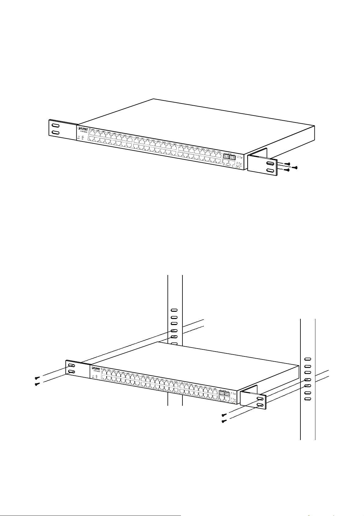
2.2.2 Rack Mounting
To install the Switch in a 19-inch standard rack, please follows the instructions described below.
Step1: Place the Switch on a hard flat surface, with the front panel positioned towards the front side.
Step2: Attach the rack-mount bracket to each side of the Switch with supplied screws attached to the package. Figure 2-3
shows how to attach brackets to one side of the Switch.
Figure 2-3 Attach brackets to the Switch.
Caution:
You must use the screws supplied with the mounting brackets. Damage caused to the parts by using incorrect screws
would invalidate the warranty.
Step3: Secure the brackets tightly.
Step4: Follow the same steps to attach the second bracket to the opposite side.
Step5: After the brackets are attached to the Switch, use suitable screws to securely attach the brackets to the rack, as shown in
Figure 2-4.
Figure 2-4 Mounting the Switch in a Rack
Step6: Proceeds with the steps 4 and steps 5 of session 2.2.1 Desktop Installation to connect the network cabling and supply
power to the Switch.
-13-
Page 14
User’s Manual of GSW-4804SF
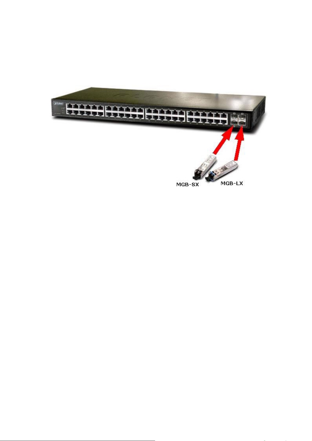
2.2.3 Installing the SFP transceiver
The sections describe how to insert an SFP transceiver into an SFP interfaces.
The SFP transceivers are hot-pluggabe and hot-swappable. You can plug-in and out the transceiver to/from any SFP interfaces
without having to power down the Switch. As the Figure 2-5 appears.
Figure 2-5 Plug-in the SFP transceiver
Approved PLANET SFP Transceivers
PLANET GSW-4804SF supports both Single-mode and Multi-mode SFP transceiver. The following list of approved PLANET
SFP transceivers is correct at the time of publication:
■ MGB-GT SFP (1000Base-T SFP transceiver )
■ MGB-SX SFP (1000Base-SX SFP transceiver )
■ MGB-LX SFP (1000Base-LX SFP transceiver )
Before connect the other switches, workstation or Media Converter.
1. Make sure both side of the SFP transceiver are with the same media type, for example: 1000Base-SX to 1000Base-SX,
1000Bas-LX to 1000Base-LX.
2. Check the fiber-optic cable type match the SFP transceiver model.
¾ To connect to 1000Base-SX SFP transceiver, use the Multi-mode fiber cable- with one side must be male duplex LC
connector type.
¾ To connect to 1000Base-LX SFP transceiver, use the Single-mode fiber cable-with one side must be male duplex
LC connector type.
-14-
Page 15
User’s Manual of GSW-4804SF
Connect the fiber cable
1. Attach the duplex LC connector on the network cable into the SFP transceiver.
2. Connect the other end of the cable to a device – switches with SFP installed, fiber NIC on a workstation or a Media
Converter.
3. Check the LNK/ACT LED of the SFP slot on the front of the Switch. Ensure that the SFP transceiver is operating correctly.
4. Check the Link mode of the SFP port if the link failed. Co works with some fiber-NICs or Media Converters, set the Link
mode to “1000” is needed.
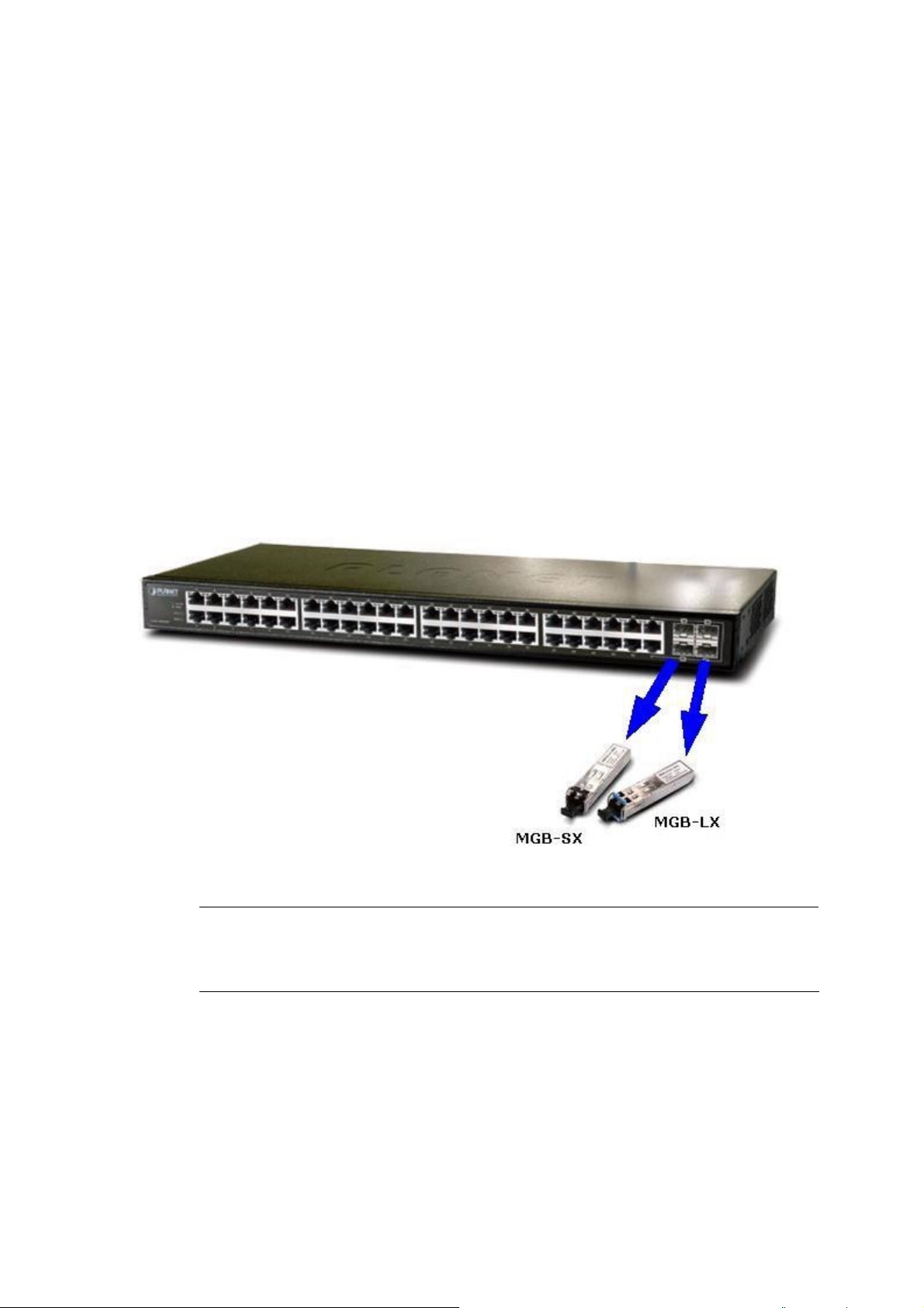
Remove the transceiver module
1. Make sure there is no network activity by consult or check with the network administrator. Or through the management
interface of the switch/converter (if available) to disable the port in advance.
2. Remove the Fiber Optic Cable gently.
3. Turn the handle of the MGB module to horizontal.
4. Pull out the module gently through the handle.
#Notice:
Figure 2-6 Pull out the SFP transceiver
Never pull out the module without pull the handle or the push bolts on the module. Direct pull out the
module with violent could damage the module and SFP module slot of the device.
-15-
Page 16

User’s Manual of GSW-4804SF
3. CONFIGURATION
This chapter explains the methods that you can use to configure management access to the Switch. It describes the types of
management applications and the communication and management protocols that deliver data between your management
device (work-station or personal computer) and the system. It also contains information about port connection options.
This chapter covers the following topics:
Management Access Overview
Administration Console Access
Reset system to factory default mode under Console interface
Web Management Access
Standards, Protocols, and Related Reading
3.1 Management Access Overview
The Switch gives you the flexibility to access and manage the Switch using any or all of the following methods:
An administration console for reset system to factory default mode
Web browser interface for Smart function configuration
The administration Web browser interface embedded in the Switch software and it is available for immediate use, and the
console interface designed for reset system to factory default mode. Both management methods have their own advantages.
Table 3-1 compares both management methods.
Method Advantages Disadvantages
Console
Web
Browser
‧Once forget or loss the IP address and
username / password, allow to reset system
to factory defult mode easily.
‧Ideal for configuring the Switch remotely.
‧Compatible with all popular browsers.
‧Can be accessed from any location.
‧Most visually appealing.
Table 3-1 Management Methods Comparison
‧Not provide further management fucntion configure ability.
‧Security can be compromised (hackers need only know the IP
address and subnet mask).
‧May encounter lag times on poor connections.
-16-
Page 17
User’s Manual of GSW-4804SF
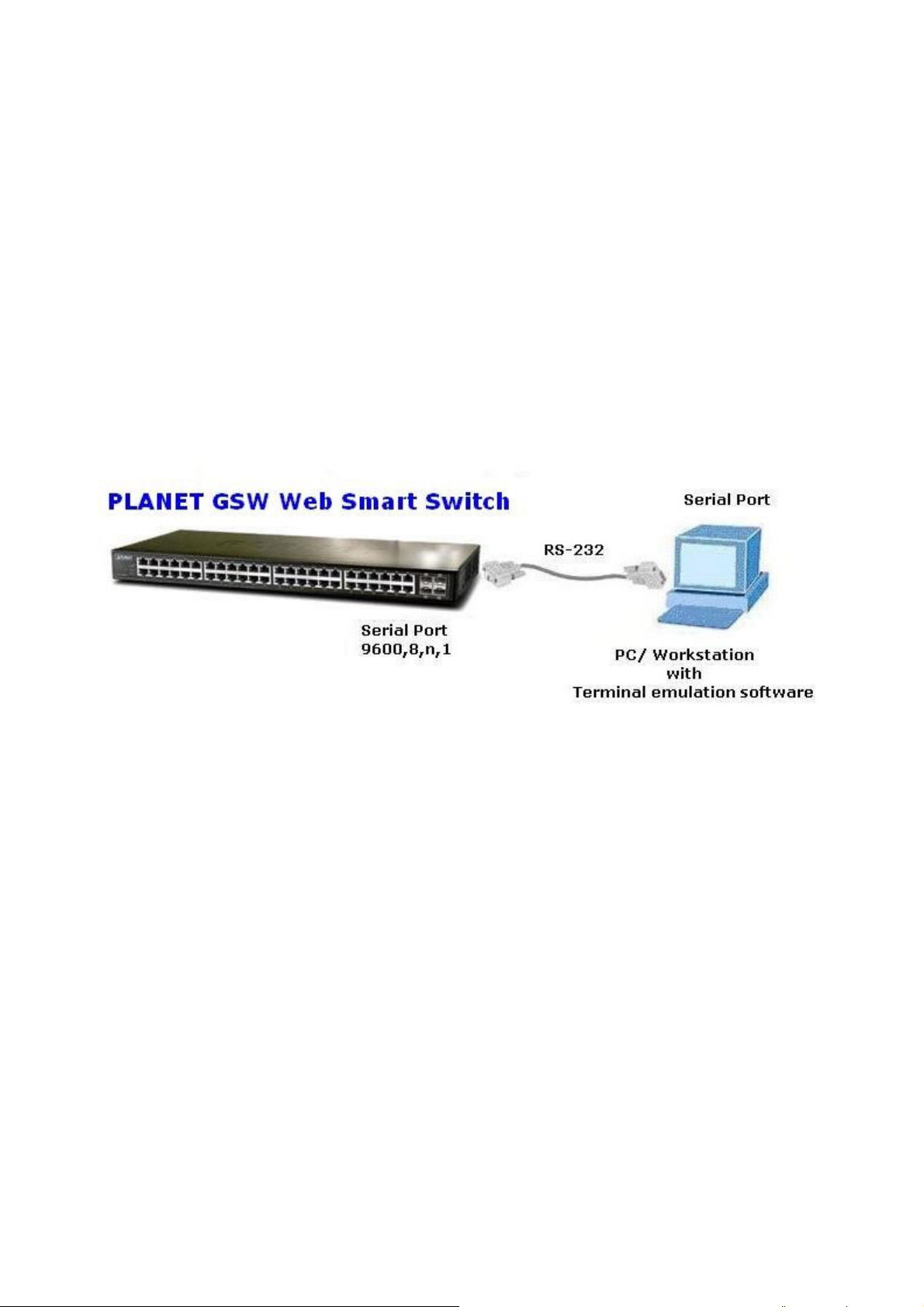
3.2 Administrator Console Access
The administration console is a local connection method between the administrator PC and the Switch. Using this method, you
can reset the Switch to factory default mode from a personal computer, Apple Macintosh, or workstation connected to the
Switch's console (Serial) port. Direct access to the administration console is achieved by directly connecting a terminal or a PC
equipped with a terminal-emulation program (such as HyperTerminal) to the Switch console (Serial) port.
When using this management method, a null-modem cable is required to connect the Switch to the PC. After making this
connection, configure the terminal-emulation program to use the following parameters:
The default parameters are:
9600 bps
8 Data bits
No Parity
1 Stop bits
No Flow Control
After log on the Switch. This Console interface is often preferred for remain connected and monitor the system during save
current system configuration or system reboots.
-17-
Page 18
User’s Manual of GSW-4804SF
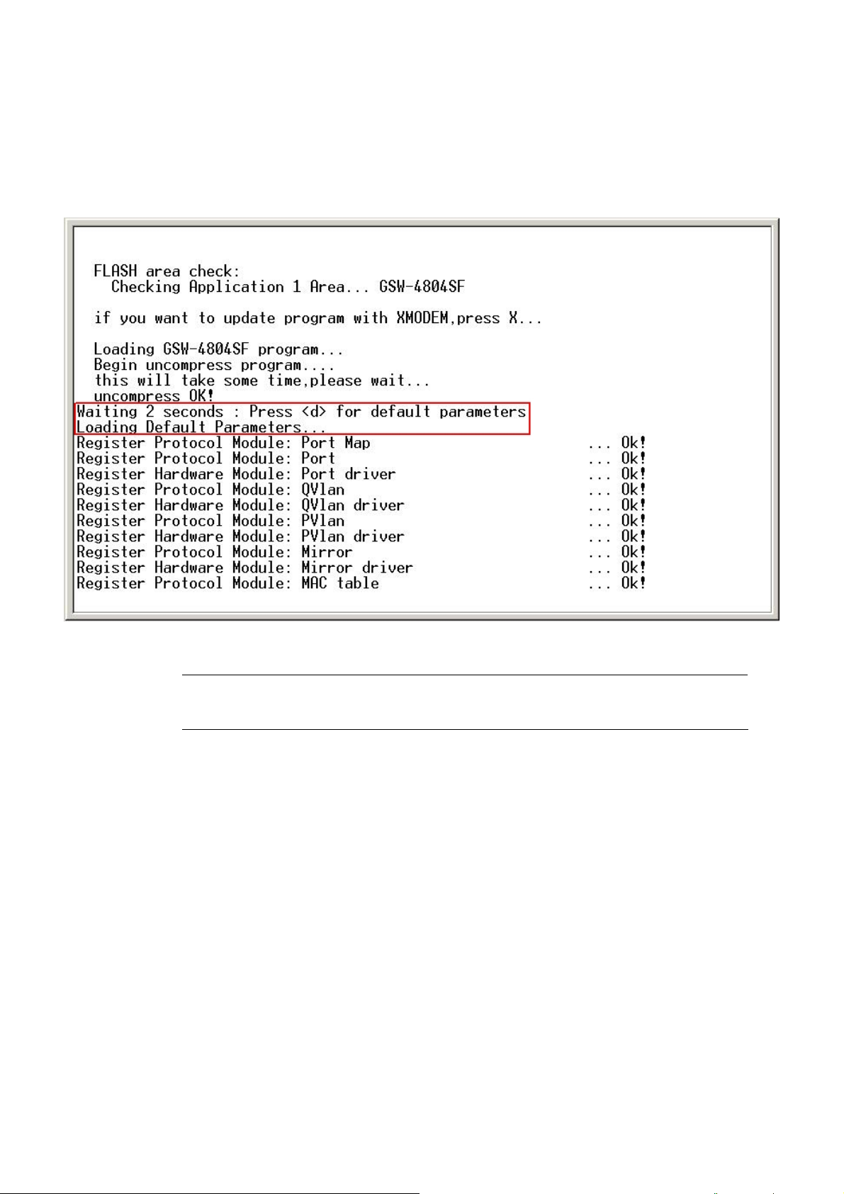
3.3 Reset to Factory Default Mode under Console Interface
Once, lose or forget the current IP address or login username / password. Once the terminal has connected to the Switch,
power on the Switch, the terminal will display that is perform the loading GSW-4804SF program procedures. When the
“ Waiting 2 seconds : Press <d> for default parameters” text appears, please press “d” from your keyboard then the Switch
will perform the reset device to factory default mode procedure and the screen appears in Figure 3-1.
#Notice:
Figure 3-1 Loading Default Parameters of GSW-4804SF
This Console interface only provide reset system to factory default mode, for further switch
management. Please access GSW-4804SF Web interface for further management.
-18-
Page 19
User’s Manual of GSW-4804SF
3.4 Web Management Access
The PLANET GSW-4804SF provides built-in browser interface. You can manage the Switch remotely by having a remote host
with Web browser, such as Microsoft Internet Explorer, Netscape Navigator or Mozilla Firefox.
The following shows how to startup the Web Management of the Switch, please note the Switch is configured through an
Ethernet connection, make sure the manager PC must be set on the same IP subnet address, for example, the default IP
address of the Switch is 192.168.0.100 (the factory-default IP address), then the manager PC should be set at 192.168.0.x
(where x is a number between 1 and 254, except 100), and the default subnet mask is 255.255.255.0.
Use Internet Explorer 5.0 or above Web browser. Enter the factory-default IP address to access the Web interface. The
factory-default IP Address as following:
http://192.168.0.100
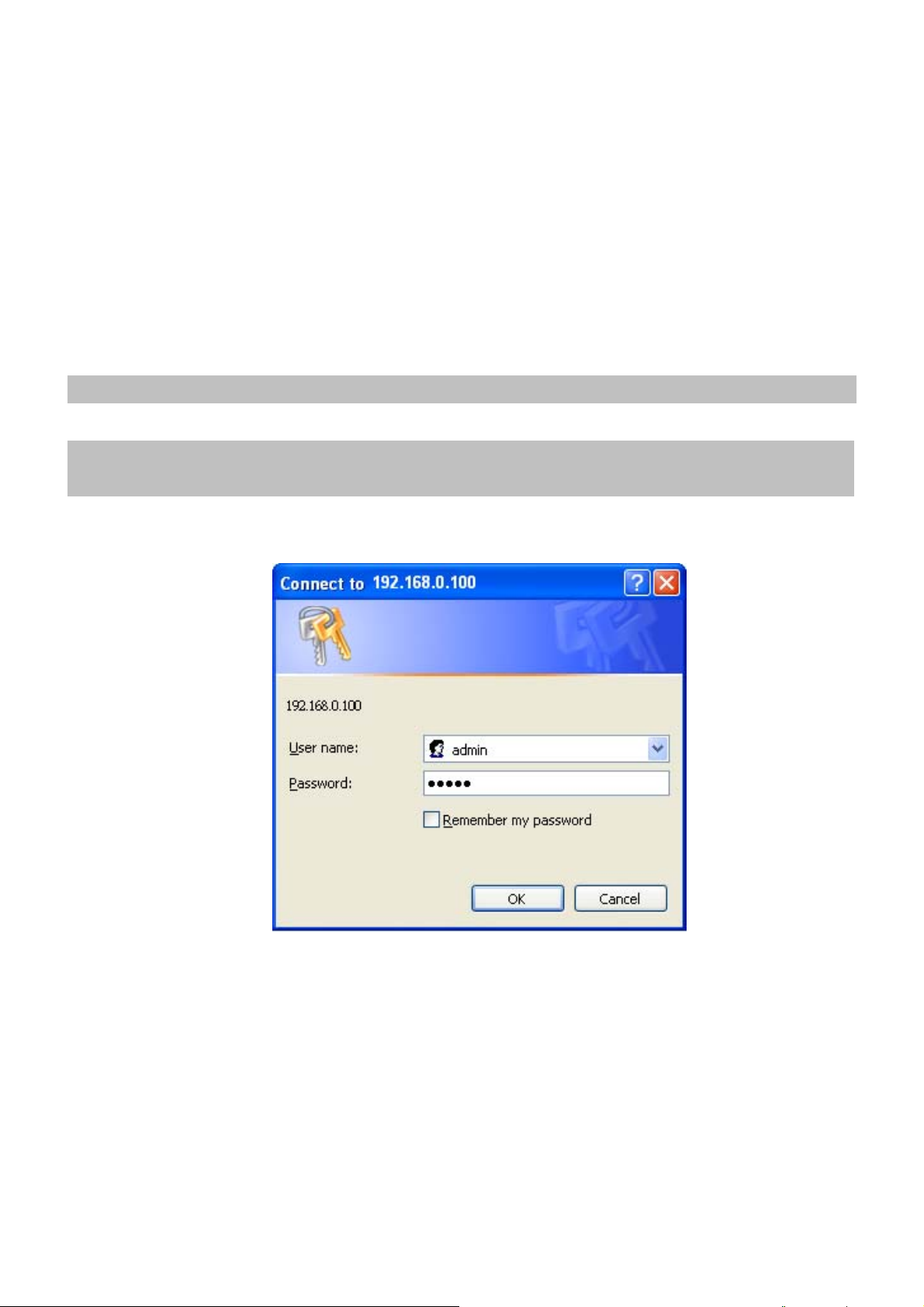
When the following login screen appears, the system will ask you to enter the username and password.
Default User Name: admin
Default Password: admin
The login screen in Figure 3-2 appears.
Figure 3-2 Web Login Screen of GSW-4804SF
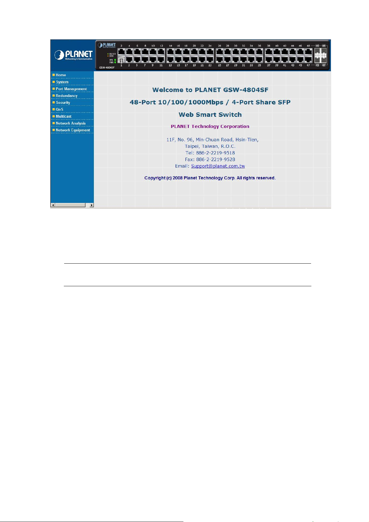
After entering the username and password (default user name and password is “admin”) in login screen (Figure 3-2 appears).
The Web main screen appears as Figure 3-3.
-19-
Page 20
User’s Manual of GSW-4804SF
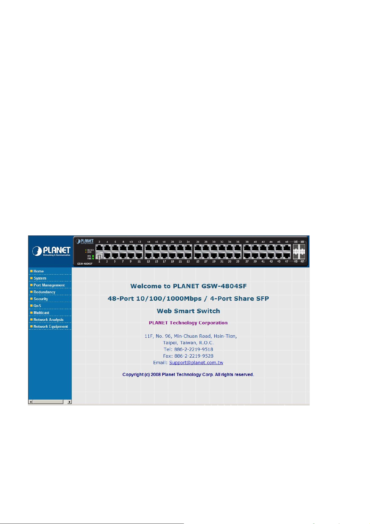
Figure 3-3 Web Main Screen of GSW-4804SF
Now, you can use the Web management interface to continue the Switch management, please refer to chapter 4 from user
manual for more.
#Notice:
For security reason, please change and memorize the new password after this first setup.
3.5 Management Architecture
All of the management application modules use the same Messaging Application Programming Interface (MAPI). By unifying
management methods with a single MAPI, configuration parameters set using one method (console port, for example) are
immediately displayable by the other management methods (for example, Web browser).
The management architecture of the Switch adheres to the IEEE open standard. This compliance assures customers that the
Switch is compatible with, and will interoperate with other solutions that adhere to the same open standard.
-20-
Page 21
User’s Manual of GSW-4804SF
4. WEB CONFIGURATION
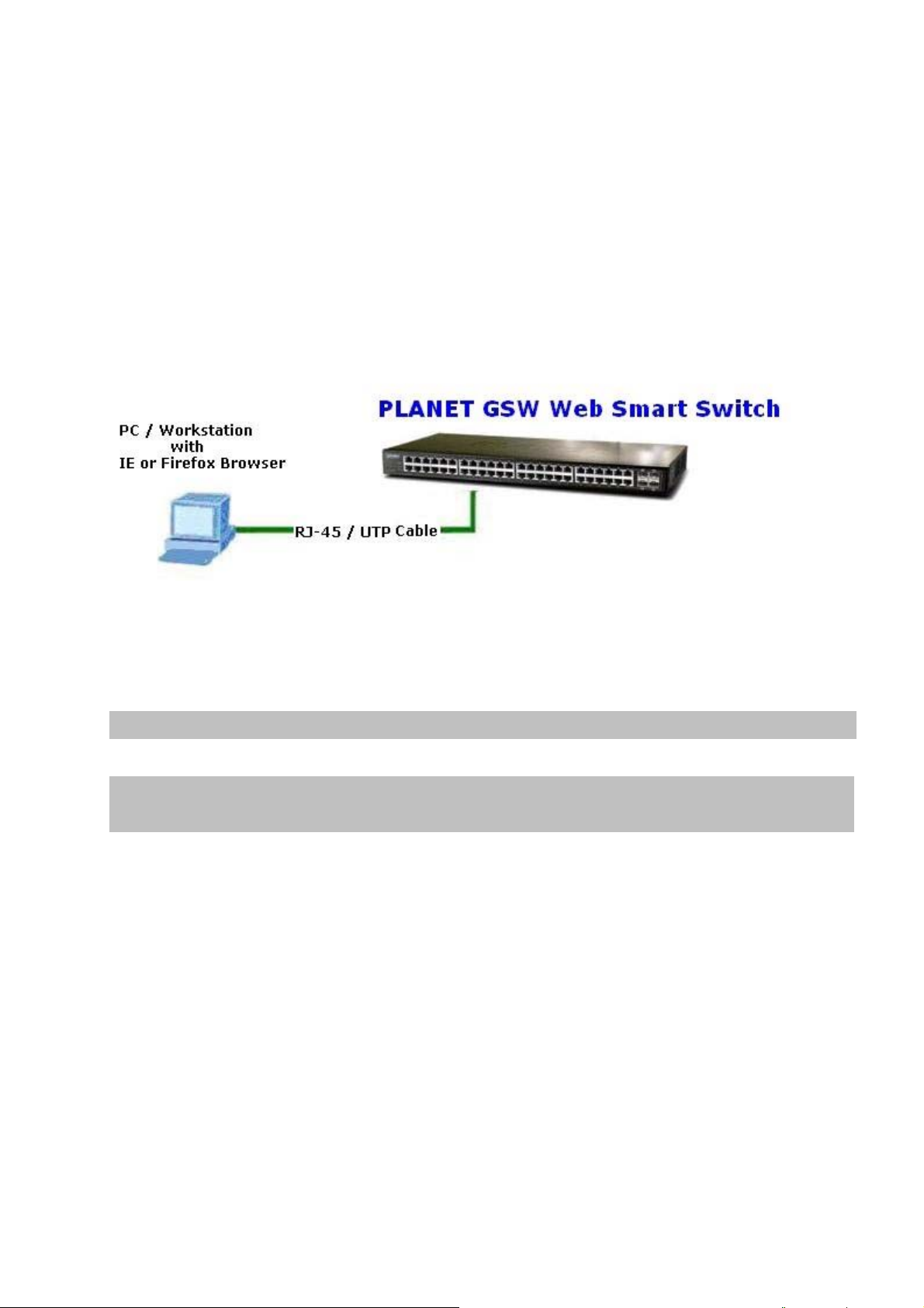
The PLANET GSW-4804SF can be configured through an Ethernet connection, make sure the manager PC must be set on
same the IP subnet address with the Switch. For example, if you have changed the default IP address (192.168.0.100) of the
Switch to 192.168.1.1 with subnet mask 255.255.255.0 via Web interface, then the manager PC should be set at 192.168.1.x
(where x is a number between 1 and 253) with subnet mask 255.255.255.0. Or you can use the factory default IP address
192.168.0.100 to do the relative configuration on manager PC. The sceen in Figure 4-1 appears.
Figure 4-1 Web Management via Ethernet
Logging on the Switch
1. Use Internet Explorer 5.0 or above Web browser. Enter the factory-default IP address to access the Web interface. The
factory-default IP Address as following:
http://192.168.0.100
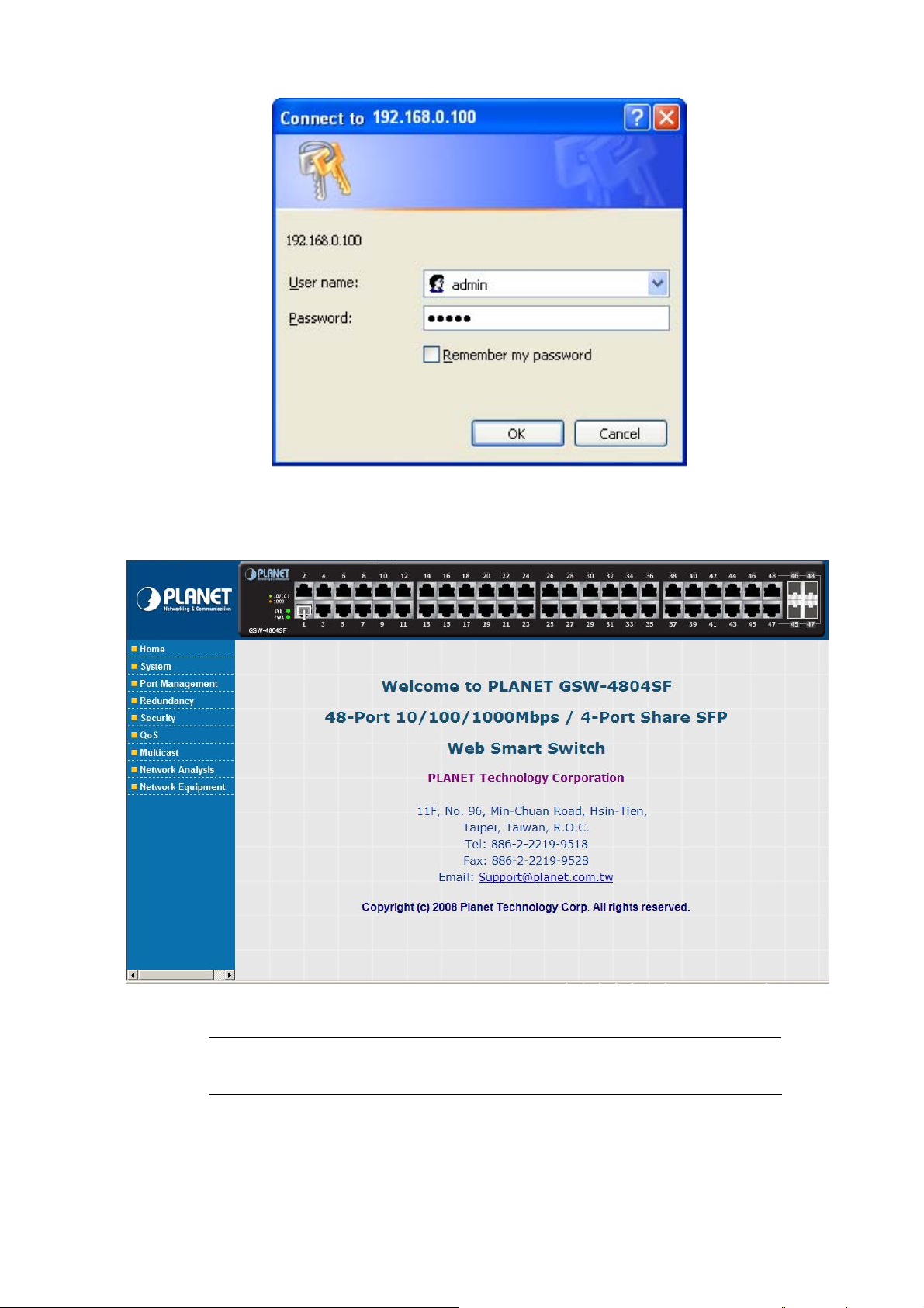
2. When the following login screen appears, the system will ask you to enter the username and password.
Default User name: admin
Default Password: admin
The login screen in Figure 4-2 appears.
-21-
Page 22
User’s Manual of GSW-4804SF
Figure 4-2 Web Login Screen of GSW-4804SF
3. After entering the username and password, the main screen appears as Figure 4-3.
Figure 4-3 Web Main Screen of GSW-4804SF
#Notice:
It is recommended to use Internet Explore 5.0 or above to access the Switch.
-22-
Page 23
User’s Manual of GSW-4804SF
The nine items and it description shown as below:
◆ Home: Provide Web Main Screen of the Switch. Explained in section 4.1.
◆ System: Provide System configuration of the Switch. Explained in section 4.2.
◆ Port Management: Provide Port Management configuration of the Switch. Explained in section 4.3.
◆ Redundancy: Provide Link Aggreation configuration of the Switch. Explained in section 4.4.
◆ Security: Provide Security configuration of of the Switch. Explained in section 4.5.
◆ QoS: Provide QoS Setting configuration of of the Switch. Explained in section 4.6.
◆ Multicast: Provide IGMP Snooping configuration of of the Switch. Explained in section 4.7.
◆ Networking Analysis: Provide Network analysis information of of the Switch. Explained in section 4.8.
◆ Network Equipment: Provide Network Equipment configuration of of the Switch. Explained in section 4.9.
4.1 Home
This section provides Web main screen display and the screen appears as Figure 4-4.
Figure 4-4 Home Web Screen
-23-
Page 24
User’s Manual of GSW-4804SF
4.2 System
This section provides IP Address, System Information, Password, Console, Management VLAN, System Upgrade,
Parameters Saving, Backup & Recovery, Load Default, Reboot and the screen appears as Figure 4-5 and Table 4-1
describes the System object of the Switch.
Figure 4-5 System Web Screen
Object Description
IP Address Allow to change the IP subnet address of the Switch. Explained in section 4.2.1.
System Information
Password Allow to change the password of the Switch. Explained in section 4.2.3.
Console Display the baudrate value of the Switch. Explained in section 4.2.4.
Management VLAN Allow to configure the Management VLAN function of the Switch. Explained in section 4.2.5.
System Upgrade Allow proceed firmware upgrade process of the Switch. Explained in section 4.2.6.
Parameters Saving Allow save current configuration of the Switch. Explained in section 4.2.7.
Backup & Recovery Allow backup and recovery the configuration file of the Switch. Explained in section 4.2.8.
Load Default Allow reset the Switch to factory default mode. Explained in section 4.2.9.
Reboot Allow reboot the Switch. Explained in section 4.2.10.
Table 4-1 Descriptions of the System Web Screen Objects
Display the Model Name, Current IP Address, Current Submask, MAC address, and Firmware
Version. Explained in section 4.2.2.
-24-
Page 25
User’s Manual of GSW-4804SF
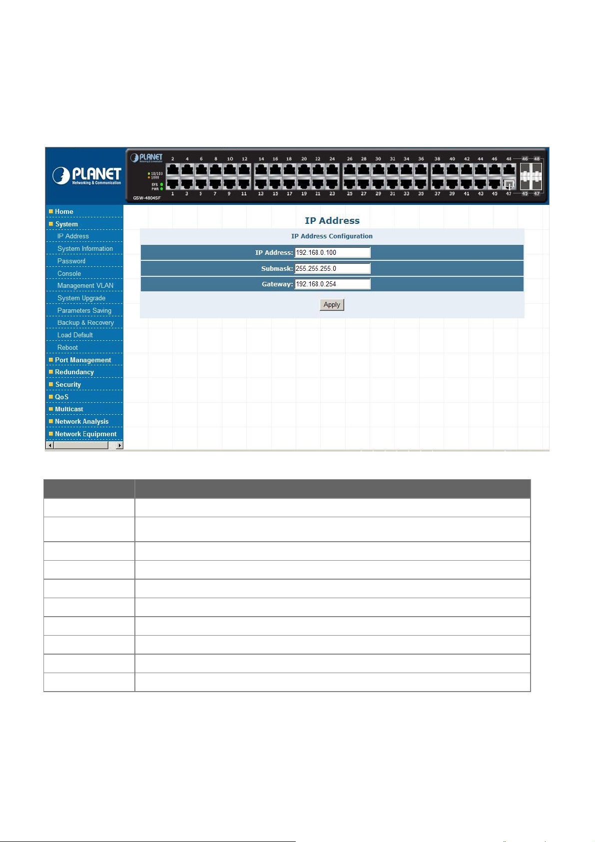
4.2.1 IP Address
This section allows modify the IP Address, Subnetmask and Gateway. After setup complete, press “Apply” button to take affect.
The screen in Figure 4-6 appears.
Figure 4-6 IP Address Web Screen
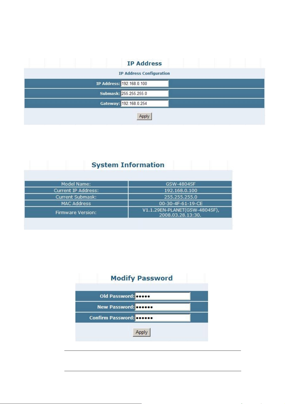
4.2.2 System Information
This section displays the System Information and the screen in Figure 4-7 appears.
Figure 4-7 System Information Web Screen
4.2.3 Password
This section allow assign new password, after setup complete. Press “Apply” button to take affect and the screen in Figure 4-8
appears.
Figure 4-8 Password Web Screen
#Notice: 1. Up to 16 characters is allowed for the Password.
2. For security reason, please change and memorize the new password
-25-
.
Page 26
User’s Manual of GSW-4804SF
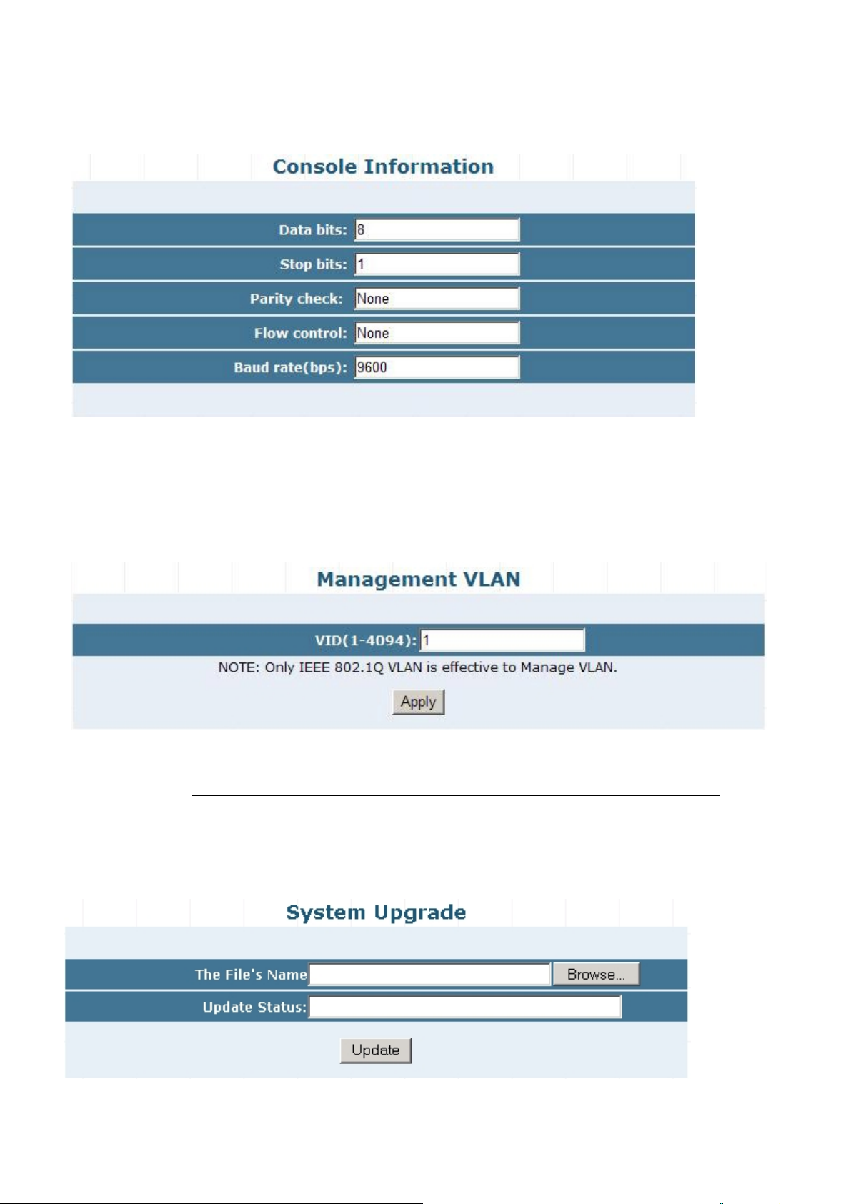
4.2.4 Console
This section displays the console baudrate setting information and the screen in Figure 4-9 appears.
Figure 4-9 Console Web Screen
4.2.5 Management VLAN
This section provides the Management VLAN configuration, after setup complete. Press “Apply” button to take affect and the
screen in Figure 4-10 appears.
Figure 4-10 Management VLAN Web Screen
#Notice: The available VLAN ID (VID) range is 1 to 4094.
4.2.6 System Upgrade
This section allows precede the firmware upgrade process and the screen in Figure 4-11 appears.
Figure 4-11 System Upgrade Web Screen
-26-
Page 27
User’s Manual of GSW-4804SF
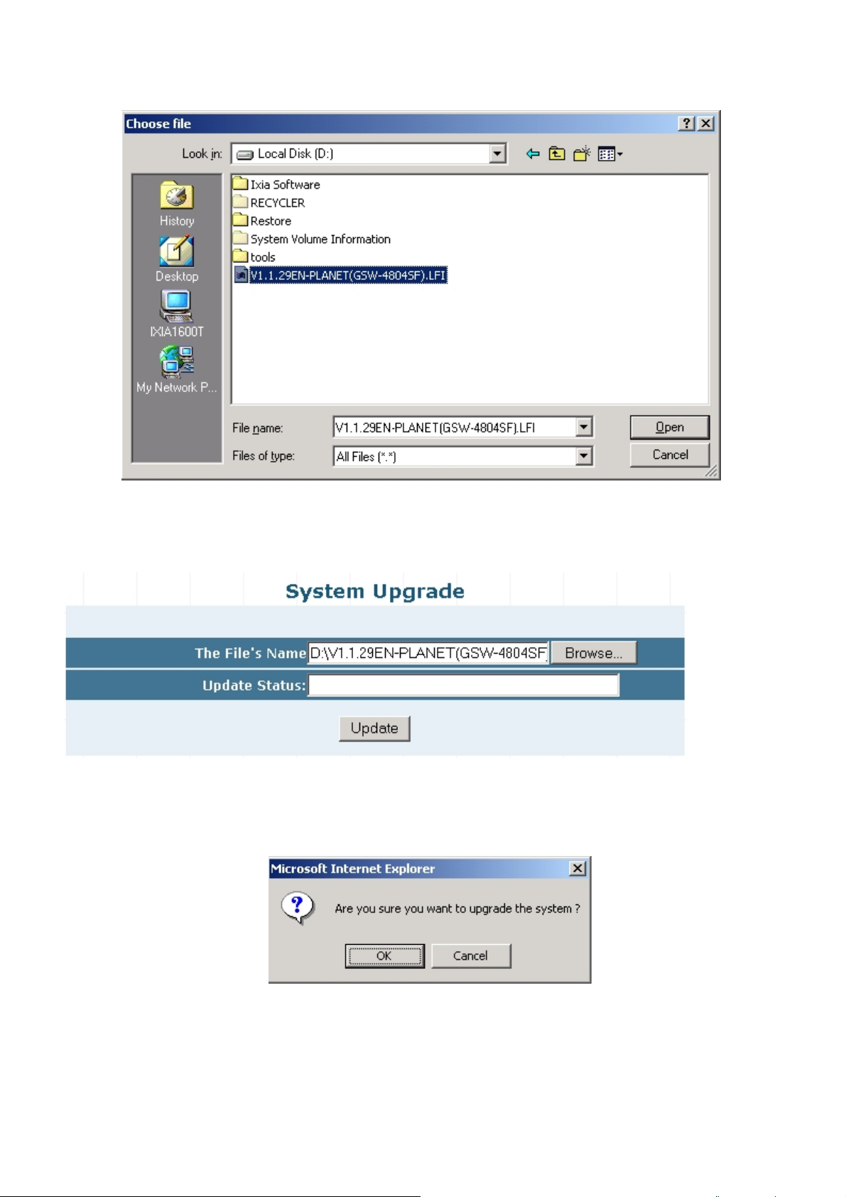
Press “Browser” button to find the firmware location administrator PC, the screen in Figure 4-12 appears.
Figure 4-12 System Upgrade Web Screen
After find the firmware location from administrator PC, press “Update” button to start the firmware upgrade process. The screen
in Figure 4-13 appears.
Figure 4-13 System Upgrade Web Screen
When the “Are you sure you want to upgrade the system ?” pop winodw appears in Figure 4-14. Please press “OK” button
to start the firmware upgrade process.
Figure 4-14 System Upgrade Web Screen
-27-
Page 28

The following firmware upgrade screen in Figure 4-15 & 4-16 appears.
Figure 4-15 System Upgrade Web Screen
User’s Manual of GSW-4804SF
Figure 4-16 System Upgrade Web Screen
When the screen above appears, please reboot the Switch for take affect. After power on completed, then you can start use the
latest firmware of GSW-4804SF.
#Notice: Please not power off the Switch during the firmware upgrade process.
-28-
Page 29
User’s Manual of GSW-4804SF
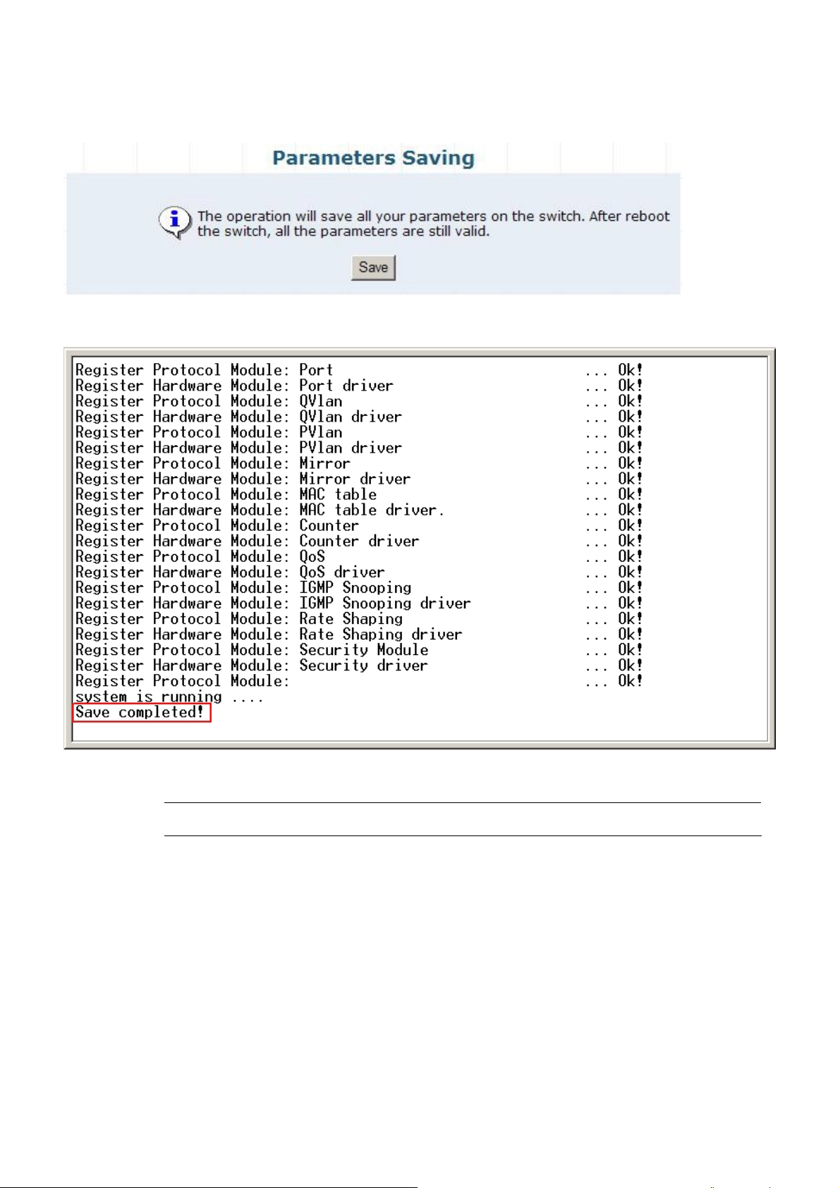
4.2.7 Parameters Saving
This section allows save current configuration and press “Save” button to take affect and the screen in Figure 4-17 appears.
Figure 4-17 Parameters Saving Web Screen
At the same time, the Parameters Saving message appears under console inetrface and the screen in Figure 4-18 appears.
Figure 4-18 Parameters Saving Console Screen
#Notice: Please save current configuration of the Switch to avoid Switch setting loss issue after Switch reboot.
-29-
Page 30
User’s Manual of GSW-4804SF
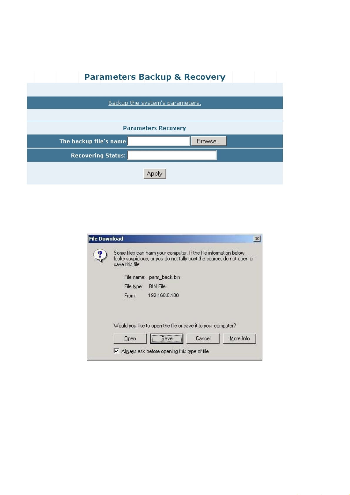
4.2.8 Backup / Recovery
This section allows backup / recover configuration and the screen in Figure 4-19 appears. This is a useful method for configure
multi-Switch devices with the same configuration in a short time.
Figure 4-19 Backup / Recovery Web Screen
Backup
Press the Backup the system's parameters and save the backup configuration file into the location of
administrator PC. The screen in Figure 4-20 & 4-21 & 4-22 appears.
Figure 4-20 Backup Web Screen
-30-
Page 31

User’s Manual of GSW-4804SF
Figure 4-21 Backup Web Screen
Figure 4-22 Backup Web Screen
-31-
Page 32

User’s Manual of GSW-4804SF
Recovery
Press “Browser” button to find the backup configuration file location of administrator PC, the screen in F igure 4-23 appears.
Figure 4-23 Recovery Web Screen
After find the backup configuration file location from administrator PC. The screen in Figure 4-24 appears.
Figure 4-24 Recovery Web Screen
Press “Apply” button then the pop window with “Are you sure want to Recover?” appears. Press “OK” to
start the configuraiton recover process. The screen in Figure 4-25 & 4-26 appears.
Figure 4-25 Recovery Web Screen
-32-
Page 33

User’s Manual of GSW-4804SF
Figure 4-26 Recovery Web Screen
When the “Upgrade Done,Please restart your system!” text appears in Recovering Status. Please power off and power on
the Switch for take affect, the screen in Figure 4-27 appears.
Figure 4-27 Recovery Web Screen
-33-
Page 34

User’s Manual of GSW-4804SF
4.2.9 Load Default
This section allows reset the Switch to factory default mode, press “Apply” button and reboot the Switch to take affect and the
screen in Figure 4-28 appears.
Figure 4-28 Load Default Web Screen
4.2.10 Reboot
This section allows reboot the Switch and press “Reboot” button to take affect, the screen in Figure 4-29 appears.
Figure 4-29 Reboot Web Screen
-34-
Page 35

User’s Manual of GSW-4804SF
4.3 Port Management
This section provides Port Configuration, Port Statistics, Band Restricting, Cascade Connecting, Link Test, Buffer Schedule,
and the screen appears as Figure 4-30 and Table 4-2 describes the Port Management object of the Switch.
Figure 4-30 Port Management Web Screen
Object Description
Port Configuration
Port Statistics
Band Restricting
Cascade Connecting
Link Test
Buffer Schedule
Table 4-2 Descriptions of the Port Management Web Screen Objects
Allow to change per port configuration of the Switch. Explained in section 4.3.1.
Display per port statistics of the Switch. Explained in section 4.3.2.
Allow to define per port bandwidth of the Switch. Explained in section 4.3.3.
Allow to define cascade port of the Switch. Explained in section 4.3.4.
Provide per port link test of the Switch. Explained in section 4.3.5.
Provide Buffer Dispatch Schedule option of the Switch. Explained in section 4.3.6.
-35-
Page 36

User’s Manual of GSW-4804SF
4.3.1 Port Configuration
This section provide per port configuration, such as Management Status Disable or Enable, Speed duplex mode selection,
Flow Control Disable or Enable. After setup completed, press “Apply” button to take affect. Also provide per port status and
the screen in Figure 4-31 appears. Table 4-3 describes the Port Configuration object of the Switch.
Figure 4-31 Port Configuration Web Screen
-36-
Page 37

Object Description
Port Configuration
Port List
Allow choose one or multi-ports for configuration.
User’s Manual of GSW-4804SF
Management Status
Speed/ Duplex Allow defining various speed duplex modes for each port, the available options are Auto, 10H, 10F,
Flow Control
Apply button Press this button to take affect.
Port Status
Port Indicate the port 1 to port 48 of the Switch.
Management Status Display per port Management Status of the Switch.
Link Status Display per port Link Status of the Switch.
Speed
Duplex
Control
Refresh button Press this button to refresh the Port Status screen.
Config Indicate the Speed mode that user configured on each port of the Switch.
Actual Indicate the current Speed mode on each port of the Switch.
Config Indicate the Duplex mode that user configured on each port of the Switch.
Actual Indicate the current Duplex mode on each port of the Switch.
Config Indicate the Flow Control mode that user configured on each port of the Switch. Flow
Actual Indicate the current Flow Control mode on each port of the Switch.
Allow choose Disable or Enable for one or multi-ports, the default mode is Enable.
100H, 100F, 1000F. The default mode is Auto.
Allow choose Disable or Enable the Flow Control for one or multi-ports, the default mode is Enable.
Table 4-3 Descriptions of the Port Configuration Web Screen Objects
#Notice: Due to the hardware restriction. The flow control function cannot across between port 1-24 and port 25-48.
-37-
Page 38

User’s Manual of GSW-4804SF
4.3.2 Port Statistics
This section display per port detail Statistics and the screen in Figure 4-32 appears. Table 4-4 describes the Port Statistics
object of the Switch.
Figure 4-32 Port Statistics Web Screen
-38-
Page 39

User’s Manual of GSW-4804SF
Object Description
Port Indicate the port 1 to port 48 of the Switch.
Management Status Display per port Management Status of the Switch.
Link Status Display per port Link Status of the Switch.
Total Bytes Of Received Packages Display per port received packages value (Unit: Bytes) of the Switch.
Received Packages Display per port received packages value of the Switch.
Total Bytes Of Send Packages Display per port send packages value (Unit: Bytes) of the Switch.
Send Packages Display per port send packages value of the Switch.
Collision Packages Display per port Collision packages value of the Switch.
Discarded Packages Display per port Discarded packages value of the Switch.
Refresh button Press this button to refresh the Port Statistics screen.
Reset button Press this button to clear all counter value the Port Statistics screen.
Table 4-4 Descriptions of the Port Statistics Web Screen Objects
Also double click one specific port of front panel from Web interface then the one specific Port Status appears in Figure 4-33.
Table 4-5 describes the Port Status object of the Switch.
Figure 4-33 Port Status Web Screen
Object Description
Port x Indicate the port 1 to port 48 of the Switch.
Management Status Display per port Management Status of the Switch.
Link Status Display per port Link Status of the Switch.
Rx Bytes Display per port received packages value (Unit: Bytes) of the Switch.
Rx Pkts Display per port received packages value of the Switch.
Tx Bytes Display per port send packages value (Unit: Bytes) of the Switch.
Tx Pkets Display per port send packages value of the Switch.
Table 4-5 Descriptions of the Port Status Web Screen Objects
-39-
Page 40

User’s Manual of GSW-4804SF
4.3.3 Band Restricting
This section provide per port Band Restricting configuration and the screen in Figure 4-34 appears. Table 4-6 describes the
Band Restricting configuration object of the Switch.
Figure 4-34 Band Restricting Web Screen
Object Description
In-Band Restrict
Ingress Port List Allow choose one or multi-ports for configuration.
Restriction Type Provide 4 different Restriction mode and the available options are Broadcast,
Broadcast And Multicast, Broadcast, Multicast And Flooded and AllFrames. Default
mode is Broadcast.
Bandwidth(100Kbps~1000000Kbps) Allow to define the Ingress bandwidth value (Unit: Kbps) for each port of the Switch.
Default mode is no setting (NA).
Out-Band Restrict
Egress Port List Allow choose one or multi-ports for configuration.
Bandwidth(100Kbps~1000000Kbps) Allow to define the Egress bandwidth value (Unit: Kbps) for each port of the Switch.
Default mode is no setting (NA).
Add button Press this button to take affect.
Port Status
Port Indicate the port 1 to port 48 of the Switch.
In-Band Restrict Type Display per port In-Band Restrict Type of the Switch.
In-Band Restrict(Kbps) Display per port In-Band Restrict value (Unit: Kbps) of the Switch.
Out-Band Restrict(Kbps) Display per port Out-Band Restrict value (Unit: Kbps) of the Switch.
Delete button Allow to remove both In-Band Restrict value and Out-Band Restrict value from per
port of the Switch.
Table 4-6 Descriptions of the Band Restricting Web Screen Objects
-40-
Page 41

User’s Manual of GSW-4804SF
4.3.4 Cascade Connecting
This section allows assign per port as Cascade Stage Port configuration and the screen in Figure 4-35 appears. Table 4-7
describes the Cascade Connecting configuration object of the Switch.
Figure 4-35 Cascade Connecting Web Screen
O Object Description
Bridge Port List Allow choose one or multi-ports.
Add button Press this button to add choose port into the Cascade Stage Port List.
Delete button
Cascade Stage Port List
Table 4-7 Descriptions of the Cascade Connecting Web Screen Objects
Allow remove specific port from the Cascade Stage Port List of the Switch.
Display the Cascade Stage Port List includes that user choose port of the Switch.
-41-
Page 42

User’s Manual of GSW-4804SF
4.3.5 Link Test
This section provides per port Link Status and the screen in Figure 4-36 appears. Table 4-8 describes the Link Status object of
the Switch.
Figure 4-36 Link Test Web Screen
Object Description
Select Port
Port Number Allow choose one port for Link Test.
Apply button Press this button to take affect.
Show Link Test Status
Port
Tx(m)
Rx(m)
Table 4-8 Descriptions of the Link Test Web Screen Objects
Indicate the port 1 to port 48 of the Switch.
Display one specific port Tx Link Status.
Display one specific port Rx Link Status.
-42-
Page 43

User’s Manual of GSW-4804SF
4.3.6 Buffer Schedule
This section provides Buffer Schedule for the system and the screen in Figure 4-37 appears. Table 4-9 describes the Buffer
Schedule object of the Switch.
Figure 4-37 Buffer Schedule Web Screen
Object Description
Buffer Dispatch Schedule
Default Set the system run at default buffer allocation mode, this mode will not drop the packets when the
Switch buffer zone is full.
Recommendatory1 Set the system run at Recommendatory1 allocation mode, this mode will drop the packets when the
Switch buffer zone is full.
Apply button Press this button to take affect.
Table 4-9 Descriptions of the Buffer Schedule Web Screen Objects
#Notice: When the configuration changed, please save current configuration and reboot the Switch for take affect.
-43-
Page 44

User’s Manual of GSW-4804SF
4.4 Redundancy
This section provides Link Aggregation Configuration and the screen appears as Figure 4-38and Table 4-10 describes the
Link Aggregation object of the Switch.
The Link Aggregation lets you group up to eight consecutive ports into a single dedicated connection. This feature can
expand bandwidth to a device on the network. Link Aggregation operation requires full-duplex mode
Port Link Aggregations can be used to increase the bandwidth of a network connection or to ensure fault recovery. Link
Aggregation lets you group up to 8 consecutive ports into a single dedicated connection between any two the Switch or other
Layer 2 switches. However, before making any physical connections between devices use the Link Aggregation Configuration
menu to specify the Link Aggregation on the devices at both ends. When using a port Link Aggregation, note that:
。 The ports used in a Link Aggregation must all be of the same media type (RJ-45, 1000Mbps fiber).
。 The ports that can be assigned to the same Link Aggregation have certain other restrictions (see below).
。 Ports can only be assigned to one Link Aggregation.
。 The ports at both ends of a connection must be configured as Link Aggregation ports.
。 None of the ports in a Link Aggregation can be configured as a mirror source port or a mirror target port.
。 All of the ports in a Link Aggregation have to be treated as a whole when moved from/to, added or deleted from a
VLAN.
。 Enable the Link Aggregation prior to connecting any cable between the switches to avoid creating a data loop.
Disconnect all Link Aggregation port cables or disable the Link Aggregation ports before removing a port Link
Aggregation to avoid creating a data loop.
It allows a maximum of eight ports to be aggregated at the same time and the Switch supports up to 12 groups. If the
group is defined as a Link Aggregationing group, then any extra ports selected are placed in a standby mode for redundancy if
one of the other ports fails. If the group is defined as a local static Link Aggregationing group, then the number of ports must be
the same as the group member ports.
Figure 4-38 Link Aggregation Web Screen
-44-
Page 45

User’s Manual of GSW-4804SF
Object Description
Aggregation Group Allow choose one Aggregation Group for further configuration of the Switch.
Port List Indicate port 1 to port 48 of the Switch.
Member Ports Display the Member Ports from per Aggregation Group of the Switch.
Add button Press this button to add specific port into specific Aggregation Group of the Switch.
Delete button
Table 4-10 Descriptions of the Link Aggregation Web Screen Objects
Press this button to remove specific port from specific Aggregation Group of the Switch.
#Notice:
Due to the hardware restriction. The Link Aggregation function cannot across between port 1-24 and port
25-48.
4.5 Security
This section provides Security Configuration, such as ACL, Security Defence, ARP Defence, VLAN, MAC Address Binding,
MAC Address Filtering, MAC Address Learning, MAC Address Aging Time and the screen appears as Figure 4-39 and Table
4-11 describes the Security object of the Switch.
Figure 4-39 Security Web Screen
-45-
Page 46

Object Description
User’s Manual of GSW-4804SF
ACL
Security Defence
ARP Defence
VLAN
MAC Address Binding
MAC Address Filtering
MAC Address Learning
MAC Address Aging Time
Table 4-11 Descriptions of the Security Web Screen Objects
Allow define the Access Control List Configuration of the Switch. Explained in section 4.5.1.
Allow define the Security Defence Policy of the Switch. Explained in section 4.5.2.
Allow define the ARP Defence Configuration of the Switch. Explained in section 4.5.3.
Allow proceed the VLAN Configuration of the Switch. Explained in section 4.5.4.
Allow proceed the MAC Address Binding Configuration of the Switch. Explained in section 4.5.5.
Allow proceed the MAC Address Filtering Configuration of the Switch. Explained in section 4.5.6.
Allow proceed the MAC Address Learning Configuration of the Switch. Explained in section 4.5.7.
Allow proceed the MAC Address Aging Time setting of the Switch. Explained in section 4.5.8.
-46-
Page 47

User’s Manual of GSW-4804SF
4.5.1 ACL
This section provides ACL configuration and View ACL Table. An ACL consists of a set of rules which are matched
sequentially against a packet. When a packet meets the match criteria of a rule, the specified rule action (Permit / Deny) is
taken and the additional rules are not checked for a match. The screen in Figure 4-40 appears
Figure 4-40 ACL Configuration Web Screen
ACL Configuration
The ACL configuration provide five various ACL type for security access control list and the available items are shown as below:
MAC.
IP.
TCP.
UDP.
ICMP.
Please refer to following sections for detail explanation.
-47-
Page 48

User’s Manual of GSW-4804SF
ACL Type: MAC
This section provide MAC ACL configuration, the screen in Figure 4-41 appears and Table 4-12 describes the MAC ACL
Configuration object of the Switch.
Object Description
ACL Type:
ACL Name:
Figure 4-41 MAC ACL Configuration Web Screen
Provide various ACL type and available options are MAC, IP, TCP, UDP, ICMP. The default ACL Type
is IP.
Allow input the ACL Name and maximum length is 10 characters.
Source MAC Address:
Destination MAC Address:
Permit/Deny:
Capture:
Policy Name:
DSCP (0-63):
Counter:
Add button Press this button to add configured MAC ACL to ACL table.
Reset button Press this button to clear whole input information that not complete setting procedure.
Policy Setup button
Allow input the Source MAC Address and the format must be “XX-XX-XX-XX-XX-XX”.
Allow input the Destination MAC Address and the format must be “XX-XX-XX-XX-XX-XX”.
Allow choosing “PERMIT” or “DENY” option and default is “PERMIT”.
Allow enable (ON) or disable (OFF) the capture ability and default is “OFF”.
Allow use user configured policy by choose specific policy; create new policy by press “Policy
Setup” button. Default is “NULL”.
Allow input DCSP value and available range from 0 to 63. Default is “No value”.
Allow input Counter information and maximum length is 10 characters. Default is “No Information”.
Provide Traffic Shaping Configuration Web screen for add QoS policy. The screen in Figure
4-42 appears and Table 4-13 describes the Traffic Shaping Configuration object of the Switch.
Table 4-12 Descriptions of the MAC ACL Type Web Screen Objects
-48-
Page 49

Figure 4-42 ACL Policy Setup Web Screen
Object Description
Add QoS Policy
Policy Name
Average (1-1000Mbps)
Burst (0-512kb)
Add button Press this button to take affect.
View QoS Policy Table
Policy Name Display the per policy name.
Average (Mbps/s) Display the average value from each policy.
Burst (kb) Display the burst value from each policy.
Allow input the new policy name and maximum length is 10 characters.
Allow input the average value and available range is 1-1000Mbps.
Allow input the burst value and available range is 0-512kb.
User’s Manual of GSW-4804SF
Delete button Press this button to delete.
Table 4-13 Descriptions of the ACL Policy Setup Web Screen Objects
-49-
Page 50

User’s Manual of GSW-4804SF
A
ACL Type: IP (Default)
This section provide IP ACL configuration, the screen in Figure 4-43 appears and Table 4-14 describes the IP ACL
Configuration object of the Switch.
Object Description
ACL Type:
ACL Name:
Provide various ACL type and available options are MAC, IP, TCP, UDP, ICMP. The default ACL Type
is IP.
Allow input the ACL Name and maximum length is 10 characters.
Figure 4-43 IP ACL Configuration Web Scree
Source IP Address:
Subnet Mask:
Destination IP Address:
Subnet Mask:
Protocol Type:
Custom (Hex,e.g. AF): Allow configure when choose OTHER in Prptocol Type.
Permit/Deny:
Capture:
Policy Name:
DSCP (0-63):
Counter:
Add button Press this button to add configured IP ACL to ACL table.
Reset button Press this button to clear whole input information that not complete setting procedure.
Policy Setup button
Allow input the Source IP Address and the format must be “XXX.XXX.XXX.XXX”.
Allow input the Source Subnet Mask address and the format must be “XXX.XXX.XXX.XXX”.
Allow input the Destination IP Address and the format must be “XXX.XXX.XXX.XXX”.
Allow input the Destination Subnet Mask address and the format must be “XXX.XXX.XXX.XXX”.
llow choose various Protocol Type and the available options are ANY, OTHER, AHP, EIGRP, ESP,
GRE, ICMP, IGMP, IPINIP, NOS, OSPF, PCP, PIM, TCP, UDP. Defult is “ANY”.
Allow choosing “PERMIT” or “DENY” option and default is “PERMIT”.
Allow enable (ON) or disable (OFF) the capture ability and default is “OFF”.
Allow use user configured policy by choose specific policy; create new policy by press “Policy
Setup” button. Default is “NULL”.
Allow input DCSP value and available range from 0 to 63. Default is “No value”.
Allow input Counter information and maximum length is 10 characters. Default is “No Information”.
Provide Traffic Shaping Configuration Web screen for add QoS policy. The screen in Figure
4-42 appears and Table 4-13 describes the Traffic Shaping Configuration object of the Switch.
Table 4-14 Descriptions of the IP ACL Type Web Screen Objects
-50-
Page 51

User’s Manual of GSW-4804SF
ACL Type: TCP
This section provide TCP ACL configuration, the screen in Figure 4-44 appears and Table 4-15 describes the TCP ACL
Configuration object of the Switch.
Object Description
ACL Type:
Provide various ACL type and available options are MAC, IP, TCP, UDP, ICMP. The default ACL Type
is IP.
Figure 4-44 TCP ACL Configuration Web Screen
ACL Name:
Source IP Address:
Subnet Mask:
Destination IP Address:
Subnet Mask:
Source Port: Allow to input the Source port information.
Destination Port: Allow to input the Destination port information.
Permit/Deny:
Capture:
Policy Name:
DSCP (0-63):
Counter:
Add button Press this button to add configured TCP ACL to ACL table.
Reset button Press this button to clear whole input information that not complete setting procedure.
Policy Setup button
Allow input the ACL Name and maximum length is 10 characters.
Allow input the Source IP Address and the format must be “XXX.XXX.XXX.XXX”.
Allow input the Source Subnet Mask address and the format must be “XXX.XXX.XXX.XXX”.
Allow input the Destination IP Address and the format must be “XXX.XXX.XXX.XXX”.
Allow input the Destination Subnet Mask address and the format must be “XXX.XXX.XXX.XXX”.
Allow choosing “PERMIT” or “DENY” option and default is “PERMIT”.
Allow enable (ON) or disable (OFF) the capture ability and default is “OFF”.
Allow use user configured policy by choose specific policy; create new policy by press “Policy
Setup” button. Default is “NULL”.
Allow input DCSP value and available range from 0 to 63. Default is “No value”.
Allow input Counter information and maximum length is 10 characters. Default is “No Information”.
Provide Traffic Shaping Configuration Web screen for add QoS policy. The screen in Figure
4-42 appears and Table 4-13 describes the Traffic Shaping Configuration object of the Switch.
Table 4-15 Descriptions of the TCP ACL Type Web Screen Objects
-51-
Page 52

User’s Manual of GSW-4804SF
ACL Type: UDP
This section provide UDP ACL configuration, the screen in Figure 4-45 appears and Table 4-16 describes the UDP ACL
Configuration object of the Switch.
Object Description
ACL Type:
Provide various ACL type and available options are MAC, IP, TCP, UDP, ICMP. The default ACL Type
is IP.
Figure 4-45 UDP ACL Configuration Web Screen
ACL Name:
Source IP Address:
Subnet Mask:
Destination IP Address:
Subnet Mask:
Source Port: Allow to input the Source port information.
Destination Port: Allow to input the Destination port information.
Permit/Deny:
Capture:
Policy Name:
DSCP (0-63):
Counter:
Add button Press this button to add configured TCP ACL to ACL table.
Reset button Press this button to clear whole input information that not complete setting procedure.
Policy Setup button
Allow input the ACL Name and maximum length is 10 characters.
Allow input the Source IP Address and the format must be “XXX.XXX.XXX.XXX”.
Allow input the Source Subnet Mask address and the format must be “XXX.XXX.XXX.XXX”.
Allow input the Destination IP Address and the format must be “XXX.XXX.XXX.XXX”.
Allow input the Destination Subnet Mask address and the format must be “XXX.XXX.XXX.XXX”.
Allow choosing “PERMIT” or “DENY” option and default is “PERMIT”.
Allow enable (ON) or disable (OFF) the capture ability and default is “OFF”.
Allow use user configured policy by choose specific policy; create new policy by press “Policy
Setup” button. Default is “NULL”.
Allow input DCSP value and available range from 0 to 63. Default is “No value”.
Allow input Counter information and maximum length is 10 characters. Default is “No Information”.
Provide Traffic Shaping Configuration Web screen for add QoS policy. The screen in Figure
4-42 appears and Table 4-13 describes the Traffic Shaping Configuration object of the Switch.
Table 4-16 Descriptions of the UDP ACL Type Web Screen Objects
-52-
Page 53

User’s Manual of GSW-4804SF
ACL Type: ICMP
This section provide ICMP ACL configuration, the screen in Figure 4-46 appears and Table 4-17 describes the ICMP ACL
Configuration object of the Switch.
Object Description
ACL Type:
Provide various ACL type and available options are MAC, IP, TCP, UDP, ICMP. The default ACL Type
is IP.
Figure 4-46 ICMP ACL Configuration Web Screen
ACL Name:
Source IP Address:
Subnet Mask:
Destination IP Address:
Subnet Mask:
Permit/Deny:
Capture:
Policy Name:
DSCP (0-63):
Counter:
Add button Press this button to add configured TCP ACL to ACL table.
Reset button Press this button to clear whole input information that not complete setting procedure.
Policy Setup button
Allow input the ACL Name and maximum length is 10 characters.
Allow input the Source IP Address and the format must be “XXX.XXX.XXX.XXX”.
Allow input the Source Subnet Mask address and the format must be “XXX.XXX.XXX.XXX”.
Allow input the Destination IP Address and the format must be “XXX.XXX.XXX.XXX”.
Allow input the Destination Subnet Mask address and the format must be “XXX.XXX.XXX.XXX”.
Allow choosing “PERMIT” or “DENY” option and default is “PERMIT”.
Allow enable (ON) or disable (OFF) the capture ability and default is “OFF”.
Allow use user configured policy by choose specific policy; create new policy by press “Policy
Setup” button. Default is “NULL”.
Allow input DCSP value and available range from 0 to 63. Default is “No value”.
Allow input Counter information and maximum length is 10 characters. Default is “No Information”.
Provide Traffic Shaping Configuration Web screen for add QoS policy. The screen in Figure
4-42 appears and Table 4-13 describes the Traffic Shaping Configuration object of the Switch.
Table 4-17 Descriptions of the ICMP ACL Type Web Screen Objects
-53-
Page 54

User’s Manual of GSW-4804SF
View ACL Table
This section provide view the ACL Table, the screen in Figure 4-47 appears and Table 4-18 describes the ACL Table object of
Switch
Figure 4-47 View ACL Table Web Screen
Object Description
Index Display the configured ACL Policy.
Type: Display the ACL Type of each ACL Policy.
Permit/Deny Display the Permit / Deny status of each ACL Policy.
Capture Display the Capture status of each ACL Policy.
Policy Name Display the Policy Name of each ACL Policy.
DSCP Display the DSCP value of each ACL Policy.
ACL Display the Name of each ACL Policy.
Counter Display the Counter information of each ACL Policy.
Status Display the Commit status or Uncommit status of each ACL Policy.
Detail Press this button to display detail setting from one specific ACL Policy.
UP Press this button to view the ACL table.
Down Press this button to view the ACL table.
Delete button Press this button to delete configured ACL Policy.
Commit
Press this button to set one specific ACL Policy status as “Commit”.
Table 4-18 Descriptions of the View ACL Table Web Screen Objects
-54-
Page 55

User’s Manual of GSW-4804SF
4.5.2 Security Defernce
This section provides Security Defence Configuration and allow choose various Security Defence rules or user defines their
own Security Defence rules for powerfull Security Defence ability under TCP / UDP port. The screen in Figure 4-48 appears.
Table 4-19 describes the Security Defence object of the Switch.
Figure 4-48 Security Defence Web Screen
Object Description
Security Defence Template Setup
Security Defence Template: Provide various type of network attack for Secunity Defence and the available options are
Worm, RPC Leak, Shake Wave, Tftp, Shock Wave, Phatbot. Default is “Worm”.
Apply button Press this button to take affect.
User-Defined Security Defence
Name:
Protocol: Provide TCP and UDP protocol options for choose.
TCP Port: Allow input TCP port when the TCP Protocol has been choosed.
UDP Port: Allow input UDP port when the UDP Protocol has been choosed.
Apply button Press this button to take affect.
Show Security Defence Entry
Name Display the Security Defence Template has been choosed.
Allow user define the name of Security Defence Template, maximum length is 10 characters.
Port List Display the TCP Port and UDP Port information from each Security Defence Template
Delete button Press this button to remove the Security Defence Template from this table list.
Table 4-19 Descriptions of the Security Defence Web Screen Objects
-55-
Page 56

User’s Manual of GSW-4804SF
4.5.3 ARP Defernce
This section provides ARP Defence Configuration and allow define ARP Attack Defence Time. The screen in Figure 4-49
appears. Table 4-20 describes the ARP Defence object of the Switch.
Figure 4-49 ARP Attack Defence Web Screen
Object Description
ARP Attack Defence Time
(10-3000ms):
Apply button Press this button to take affect.
Table 4-20 Descriptions of the ARP Defence Web Screen Objects
Allow configuring the ARP Attack Defence Time and available range is 10 to 3000ms. Default
is no setting.
-56-
Page 57

User’s Manual of GSW-4804SF
4.5.4 VLAN
This section provides VLAN Configuration and the available options are 802.1Q VLAN and Port-Based VLAN. Before use the
VLAN Configuration, please read following VLAN theorem completely before continuing.
VLAN Description
A Virtual Local Area Network (VLAN) is a network topology configured according to a logical scheme rather than the physical
layout. VLAN can be used to combine any collection of LAN segments into an autonomous user group that appears as a
single LAN. VLAN also logically segment the network into different broadcast domains so that packets are forwarded only
between ports within the VLAN. Typically, a VLAN corresponds to a particular subnet, although not necessarily.
VLAN can enhance performance by conserving bandwidth, and improve security by limiting traffic to specific domains.
A VLAN is a collection of end nodes grouped by logic instead of physical location. End nodes that frequently communicate
with each other are assigned to the same VLAN, regardless of where they are physically on the network. Logically, a VLAN
can be equated to a broadcast domain, because broadcast packets are forwarded to only members of the VLAN on which the
broadcast was initiated.
#Notice:
Port-based VLAN
Port-based VLAN limit traffic that flows into and out of switch ports. Thus, all devices connected to a port are members of the
VLAN(s) the port belongs to, whether there is a single computer directly connected to a switch, or an entire department.
On port-based VLAN.NIC do not need to be able to identify 802.1Q tags in packet headers. NIC send and receive normal
Ethernet packets. If the packet's destination lies on the same segment, communications take place using normal Ethernet
protocols. Even though this is always the case, when the destination for a packet lies on another switch port, VLAN
considerations come into play to decide if the packet is dropped by the Switch or delivered.
1. No matter what basis is used to uniquely identify end nodes and assign these nodes
VLAN membership, packets cannot cross VLAN without a network device performing a routing
function between the VLAN.
2. The Switch supports Port-based VLAN and IEEE 802.1Q VLAN. The port untagging function can be
used to remove the 802.1 tag from packet headers to maintain compatibility with devices that are
tag-unaware.
3. The Switch's default is to assign all ports to a single 802.1Q VLAN named DEFAULT_VLAN. As new
VLAN is created, the member ports assigned to the new VLAN will be removed from the DEFAULT_
VLAN port member list. The DEFAULT_VLAN has a VID = 1.
-57-
Page 58

User’s Manual of GSW-4804SF
IEEE 802.1Q VLANs
IEEE 802.1Q (tagged) VLAN are implemented on the Switch. 802.1Q VLAN require tagging, which enables them to span the
entire network (assuming all switches on the network are IEEE 802.1Q-compliant).
VLAN allow a network to be segmented in order to reduce the size of broadcast domains. All packets entering a VLAN will
only be forwarded to the stations (over IEEE 802.1Q enabled switches) that are members of that VLAN, and this includes
broadcast, multicast and unicast packets from unknown sources.
VLAN can also provide a level of security to your network. IEEE 802.1Q VLAN will only deliver packets between stations that
are members of the VLAN. Any port can be configured as either tagging or untagging. The untagging feature of IEEE 802.1Q
VLAN allows VLAN to work with legacy switches that don't recognize VLAN tags in packet headers. The tagging feature
allows VLAN to span multiple 802.1Q-compliant switches through a single physical connection and allows Spanning Tree to
be enabled on all ports and work normally.
Any port can be configured as either tagging or untagging. The untagging feature of IEEE 802.1Q VLAN allow VLAN to work
with legacy switches that don’t recognize VLAN tags in packet headers. The tagging feature allows VLAN to span multiple
802.1Q-compliant switches through a single physical connection and allows Spanning Tree to be enabled on all ports and
work normally.
Some relevant terms:
Tagging - The act of putting 802.1Q VLAN information into the header of a packet.
Untagging - The act of stripping 802.1Q VLAN information out of the packet header.
802.1Q VLAN Tags
The figure below shows the 802.1Q VLAN tag. There are four additional octets inserted after the source MAC address. Their
presence is indicated by a value of 0x8100 in the Ether Type field. When a packet's Ether Type field is equal to 0x8100, the
packet carries the IEEE 802.1Q/802.1p tag. The tag is contained in the following two octets and consists of 3 bits of user
priority, 1 bit of Canonical Format Identifier (CFI - used for encapsulating Token Ring packets so they can be carried across
Ethernet backbones), and 12 bits of VLAN ID (VID). The 3 bits of user priority are used by 802.1p. The VID is the VLAN
identifier and is used by the 802.1Q standard. Because the VID is 12 bits long, 4094 unique VLAN can be identified.
The tag is inserted into the packet header making the entire packet longer by 4 octets. All of the information originally
contained in the packet is retained.
802.1Q VLAN Tags
User Priority CFI VLAN ID (VID)
3 bits 1 bits 12 bits
TPID (Tag Protocol Identifier) TCI (Tag Control Information)
2 bytes 2 bytes
Preamble Destination
Address
Source
Address
VLAN TAG Ethernet
Type
Data FCS
6 bytes 6 bytes 4 bytes 2 bytes 46-1517 bytes 4 bytes
-58-
Page 59

User’s Manual of GSW-4804SF
The Ether Type and VLAN ID are inserted after the MAC source address, but before the original Ether Type/Length or Logical
Link Control. Because the packet is now a bit longer than it was originally, the Cyclic Redundancy Check (CRC) must be
recalculated.
Adding an IEEE 802.1Q Tag
Dest. Addr. Src. Addr. Length/E. type Data Old CRC
Original Ethernet
Dest. Addr. Src. Addr. E. type Tag Length/E. type Data New CRC
Priority CFI VLAN ID
New Tagged Packet
Port VLAN ID
Packets that are tagged (are carrying the 802.1Q VID information) can be transmitted from one 802.1Q compliant network
device to another with the VLAN information intact. This allows 802.1Q VLAN to span network devices (and indeed, the entire
network – if all network devices are 802.1Q compliant).
Every physical port on a switch has a PVID. 802.1Q ports are also assigned a PVID, for use within the switch. If no VLAN are
defined on the switch, all ports are then assigned to a default VLAN with a PVID equal to 1. Untagged packets are assigned the
PVID of the port on which they were received. Forwarding decisions are based upon this PVID, in so far as VLAN are concerned.
Tagged packets are forwarded according to the VID contained within the tag. Tagged packets are also assigned a PVID, but the
PVID is not used to make packet forwarding decisions, the VID is.
Tag-aware switches must keep a table to relate PVID within the switch to VID on the network. The switch will compare the VID of
a packet to be transmitted to the VID of the port that is to transmit the packet. If the two VID are different the switch will drop the
packet. Because of the existence of the PVID for untagged packets and the VID for tagged packets, tag-aware and tag-unaware
network devices can coexist on the same network.
A switch port can have only one PVID, but can have as many VID as the switch has memory in its VLAN table to store them.
Because some devices on a network may be tag-unaware, a decision must be made at each port on a tag-aware device before
packets are transmitted – should the packet to be transmitted have a tag or not? If the transmitting port is connected to a
tag-unaware device, the packet should be untagged. If the transmitting port is connected to a tag-aware device, the packet
should be tagged.
Default VLANs
The Switch initially configures one VLAN, VID = 1, called "default." The factory default setting assigns all ports on the Switch to
the "default". As new VLAN are configured in Port-based mode, their respective member ports are removed from the "default."
VLAN and Link aggregation Groups
In order to use VLAN segmentation in conjunction with port link aggregation groups, you can first set the port link aggregation
group(s), and then you may configure VLAN settings. If you wish to change the port link aggregation grouping with VLAN
already in place, you will not need to reconfigure the VLAN settings after changing the port link aggregation group settings.
VLAN settings will automatically change in conjunction with the change of the port link aggregation group settings
-59-
Page 60

User’s Manual of GSW-4804SF
802.1Q VLAN Configuration
There are up to 256 configurable VLAN groups. By default when 802.1Q is enabled, all ports on the switch belong to default
VLAN (VID 1). The default VLAN cannot be deleted.
Understand nomenclature of the Switch
Tagging and Untagging
Every port on an 802.1Q compliant switch can be configured as tagging or untagging.
。 Tagging: Ports with tagging enabled will put the VID number, priority and other VLAN information into the header of
all packets that flow into those ports. If a packet has previously been tagged, the port will not alter the
packet, thus keeping the VLAN information intact. The VLAN information in the tag can then be used by
other 802.1Q compliant devices on the network to make packet-forwarding decisions.
。 Untagging: Ports with untagging enabled will strip the 802.1Q tag from all packets that flow into those ports. If the
packet doesn't have an 802.1Q VLAN tag, the port will not alter the packet. Thus, all packets received
by and forwarded by an untagging port will have no 802.1Q VLAN information. (Remember that the
PVID is only used internally within the Switch). Untagging is used to send packets from an
802.1Q-compliant network device to a non-compliant network device.
Frame Income
Frame Leave
Leave port is tagged Frame remains tagged Tag is inserted
Leave port is untagged Tag is removed Frame remain untagged
Here pay attention to the explainion of “Access”,”Always Untag” and “Trunk”.
。 Access: Ports will strip the 802.1Q tag from all packets that out of those ports. If the packet doesn’t have an 802.1Q
VLAN tag, the port will not alter the packet. Thus, all packets received by and forwarded by an untagging port will
have no 802.1Q VLAN information. Untagging is used to send packets from an 802.1Q-compliant network device to
a non-compliant network device.
Ports with “Access” mode belong to a single untagged VLAN.
。 Trunk: Ports with tagging enabled will put the VID number, priority and other VLAN information into the header of all
packets that out of those ports. If a packet has previously been tagged, the port will not alter the packet, thus
keeping the VLAN information intact. The VLAN information in the tag can then be used by other 802.1Q
compliant devices on the network to make packet forwarding decisions.
Income Frame is tagged Income Frame is untagged
。 Always Untag: The port belongs to VLANs, and each VLAN is user-defined as tagged or untagged (full 802.1Q
mode). Ports will strip the 802.1Q tag from all packets that out of those ports.
-60-
Page 61

User’s Manual of GSW-4804SF
Port Mode VLAN Membership Frame Leave
Access Belongs to a single untagged VLAN
Always Untag
Trunk
Port VID (PVID)
Set the port VLAN ID that will be assigned to untagged traffic on a given port. This feature is useful for accommodating devices
that you want to participate in the VLAN but that don’t support tagging. The Switch allows each port to set one PVID, the range
is 1~255, default PVID is 1. The PVID must be the same as the VLAN ID that the port was defined as belonging to in the VLAN
group, or the untagged traffic will be dropped.
1. Select 802.1Q VLAN in the VLAN Type field and click on the “Apply” button.
Allowed to belongs to multiple untagged
VLANs at the same time
Allowed to belongs to multiple Tagged
VLANs at the same time
(Tag=PVID or Original VID be remained)
( Tag=PVID be removed)
Untagged
Untagged
(Tag=PVID be removed)
Tagged
Figure 4-50 802.1Q VLAN Type Web Screen
The main page then changes to the 802.1Q VLAN table which displays the VLAN configuration of each port.
Figure 4-51 802.1Q VLAN Configuration Web Screen
-61-
Page 62

User’s Manual of GSW-4804SF
2. If you want to configure port #2 to be in a VLAN other than default VLAN. Double click on “port2” to enter into VLAN port
configuration window.
Figure 4-52 802.1Q VLAN Port Configuration Web Screen
3. Choose the Link Type in the drop drop down menu: Access, Trunk or Always Untag
Note that if the Access type is chosen, it will strip the 802.1Q tag from all packets that out of this port. On the other hand, if the
Trunk type is chosen, it will put the VID number, priority and other VLAN information into the header of all packets that out of
this port. And if the Always Untag type is chosen, it will strip the 802.1Q tag from all packets that out of the port. But the port
can be assigned to more than one VLAN group.
4. Define the PVID for the port
Set the port VLAN ID that will be assigned to untagged traffic on a given port. This feature is useful for accommodating
devices that you want to participate in the VLAN but that don’t support tagging.
Figure 4-53 Define Per Port PVID Web Screen
-62-
Page 63

User’s Manual of GSW-4804SF
5. Trunk configuration: If the Trunk type is chosen, please follow the steps to set the Trunk of the port.
5.1 Add and define the names and VIDs for new VLANs. The VID number ranges from 2 to 4094. Fill the VID field and the
VLAN Name field in the Set VLAN’s VID & Name table and click on the “Add/Modify” button to save.
Figure 4-54 Define Per VLAN Group Web Screen
5.2 The added new VLAN then shows the the VLAN Table field in the Set Trunk Port for VLAN table.
Figure 4-55 Define Per VLAN Group Web Screen
5.3 Select on the VLAN chich you want to tag with in the VLAN Table field and click on the “Add” button to add. This will add
the VLAN in to the VLAN with The Trunk Port field.
Figure 4-56 Define Per VLAN Group Web Screen
5.4 Click on the “close” button to close the VLAN port configuration table of port #2, and back to the 802.1Q main page.
5.5 Click on the “Show VLAN Members” button to show the VLAN members.
Figure 4-57 Show VLAN Members Web Screen
-63-
Page 64

User’s Manual of GSW-4804SF
5.6 As shows in the following screen:
Figure 4-58 Show VLAN Members Web Screen
Port-based VLAN Configuration
Packets can only be broadcast among other members of the same VLAN group. Note all unselected ports are treated as
belonging to the default system VLAN. If port-based VLAN are enabled, then VLAN-tagging is ignored.
1. On VLAN Configuration table, choose Port-based VLAN. Click on the “Apply” button.
Figure 4-59 Port-Based VLAN Type Web Screen
2. The main page then change to Port-base VLAN table, click on the “Add/Modify” button to create a new VLAN group.
Figure 4-60 Port-Based VLAN Configuration Web Screen
3. The Port-base VLAN Confirutation table then pops up, enter the VLAN group ID, VLAN name and select the member ports
for the VLAN.
4. Click the “Apply” button to add the VLAN.
5. Select the ports in the Port List field and click on the Add button to add the member ports to the VLAN. The selected VLAN
member then shows in the VLAN Member field.
-64-
Page 65

User’s Manual of GSW-4804SF
Figure 4-61 Port-Based VLAN Configuration Web Screen
6. Click on the “Close” button and back to the Port-based VLAN main page.
The “Show VLAN Member” button is to list the valid VLANs. You can also remove the added VALN by click on this button.
Figure 4-62 Show VLAN Members Web Screen
Figure 4-63 Show VLAN Members Web Screen
-65-
Page 66

User’s Manual of GSW-4804SF
4.5.5 MAC Address Binding
This section provides MAC Address Binding Configuration and the screen in Figure 4-64 appears. Table 4-21 describes the
MAC Address Binding object of the Switch.
This function is based upon for the Switch security. When you add one MAC Address is bind with one port. It remains in the
switch's address table, regardless of whether the device is physically connected to the switch. This saves the switch from
having to re-learn a device's MAC address after it has been disconnected or powered-off from the network, and then
reconnected at some time later. If the Network station is connected with one port want to control the switch, the station’s MAC
Address must be the same as one MAC Address
To bind the MAC Address, click on the Security / MAC Address Binding menu button, the main web page then shows the
MAC Address Bind function table.
1. Fill the MAC Address field with MAC address in the format “XX-XX-XX-XX-XX-XX “ and choose the port to bind the MAC
Address in the Port field.
2. Click on the “Add” button.
3. To remove the MAC Address binded by the port. Simply click on the “Delete” button of the MAC Address in the Show MAC
Address Table.
Figure 4-64 MAC Address Binding Web Screen
-66-
Page 67

Object Description
Bind New MAC Address
User’s Manual of GSW-4804SF
MAC Address
Port Choose one specific port for new input MAC Adress binding.
Add button Press this button to add the new input MAC Address binding on one specific port.
Show MAC Address Table
MAC Address Display the binding MAC Address on one specific port.
Port Display the port with binding MAC Address.
Delete button Press this button for remove the binding MAC Address from the specific port.
Go Press this button for go to specific page of MAC Address Table.
Previous Press this button for back to previous page of MAC Address Table.
Next Press this button for go to next page of MAC Address Table.
#Notice:
The Switch provide maximum up to 800 binding MAC Address, 400 MAC address for port 1 to port 24,
400 MAC address for port 25 to port 28.
Allow input the MAC Address and the format must be “XX-XX-XX-XX-XX-XX”.
Table 4-21 Descriptions of the MAC Address Binding Web Screen Objects
-67-
Page 68

User’s Manual of GSW-4804SF
4.5.6 MAC Address Filtering
This section provides MAC Address Filtering Configuration and the screen in Figure 4-65 appears. Table 4-22 describes the
MAC Address Filtering object of the Switch.
The MAC address Filtering allows the Switch to drop unwanted traffic. Traffic is filtered based on the destination addresses.
To filter the MAC Address, click on the Security / MAC Address Filtering menu button, the main web page then shows the
MAC Address Filtering function table.
1. Fill the MAC Address field with MAC address in the format “XX-XX-XX-XX-XX-XX “.
2. Click on the “Add” button to add.
3. To remove the MAC Address filtered by the port. Simply click on the “Delete” button of the MAC Address in the Current
Filtering MAC Table.
Figure 4-65 MAC Address Filtering Web Screen
Object Description
Add New MAC Address
Add New MAC Address
Add button Press this button to add the new input filtering MAC Address.
Current Filtering MAC Address
MAC Address Display the filtering MAC Address.
Delete button Press this button for remove the filtering MAC Address.
Table 4-22 Descriptions of the MAC Address Filtering Web Screen Objects
The Switch provide maximum up to 800 filtering MAC Address
Allow input the filtering MAC Address and the format must be “XX-XX-XX-XX-XX-XX”.
#Notice:
-68-
Page 69

User’s Manual of GSW-4804SF
4.5.7 MAC Address Learning
This section provides MAC Address Learning Configuration and the screen in Figure 4-66 appears. Table 4-23 describes the
MAC Address Learning object of the Switch.
The Switch is able to disable MAC Address learning function on ports.
1. Fill the Port List field in the MAC Address Learning table and select Enable/Disable in the MAC Address Learning field.
2. Click on the “Apply” button to take affect
Figure 4-66 MAC Address Learning Web Screen
Object Description
MAC Address Learning
Port List Allow choose one or multi-ports for MAC Address Learning Configuration.
MAC Address Learning
Apply button Press this button to take affect.
Show Port Table
Port Indicate Port 1 to Port 48 of the Switch..
MAC Address Learning Display per port MAC Address Learning status.
Table 4-23 Descriptions of the MAC Address Learning Web Screen Objects
Allow Disable or Enable the MAC Address Learning function. Default is “Disable”.
-69-
Page 70

User’s Manual of GSW-4804SF
A
4.5.8 MAC Address Aging Time
This section provides MAC Address Aging Time Configuration and the screen in Figure 4-67 appears. Table 4-24 describes
the MAC Address Aging Time object of the Switch.
The Aging Time affects the learning process of the Switch. Dynamic forwarding table entries, which are made up of the source
and destination MAC addresses and their associated port numbers, are deleted from the table if they are not accessed within
the aging time.
The aging time can be from 30 to 1,000 seconds with a default value of 300 seconds. A very long aging time can result in
dynamic forwarding table entries that are out-of-date or no longer exist. This may cause incorrect packet forward indecisions
by the Switch.
If the Aging Time is too short however, many entries may be aged out too soon. This will result in a high percentage of
received packets whose source addresses cannot be found in the forwarding table, in which case the switch will broadcast the
packet to all ports, negating many of the benefits of having a switch.
Static forwarding entries are not affected by the aging time.
To set the Aging Time, enter the number in the MAC Address Aging Time field, and click on the “Apply” button to save. The
valid range is 30-1000 seconds. Default is 300 seconds.
Figure 4-67 MAC Address Aging Time Web Screen
Object Description
MAC Address Aging Time
(30-1000 seconds)
Apply button Press this button to take affect.
llow define the MAC Address Aging Time and the available range is 30 to 1000 seconds.
Default is “300” seconds.
Table 4-24 Descriptions of the MAC Address Aging Time Web Screen Objects
-70-
Page 71

User’s Manual of GSW-4804SF
4.6 QoS
This section provides QoS Configuration, such as 802.1p-Queue Mapping, Port Default Priority, Queue Management, Trust
Mode and the screen appears as Figure 4-68 and Table 4-25 describes the QoS object of the Switch.
Figure 4-68 QoS Web Screen
Object Description
802.1p-Queue Mapping
Port Default Priority
Queue Management
Trust Mode
Table 4-25 Descriptions of the QoS Web Screen Objects
Provide 802.1p-Queue Mapping Configuration of the Switch. Explained in section 4.6.1.
Provide Port Default Priority Configuration of the Switch. Explained in section 4.6.2.
Provide Queue Management Configuration of the Switch. Explained in section 4.6.3.
Provide Turst Mode Configuration of the Switch. Explained in section 4.6.4.
-71-
Page 72

User’s Manual of GSW-4804SF
Understand QOS
Quality of Service (QoS) is an advanced traffic prioritization feature that allows you to establish control over network traffic. QoS
enables you to assign various grades of network service to different types of traffic, such as multi-media, video, protocol-specific,
time critical, and file-backup traffic.
QoS reduces bandwidth limitations, delay, loss, and jitter. It also provides increased reliability for delivery of your data and
allows you to prioritize certain applications across your network. You can define exactly how you want the switch to treat
selected applications and types of traffic.
You can use QoS on your system to:
。 Control a wide variety of network traffic by:
。 Classifying traffic based on packet attributes.
。 Assigning priorities to traffic (for example, to set higher priorities to time-critical or business-critical applications).
。 Applying security policy through traffic filtering.
。 Provide predictable throughput for multimedia applications such as video conferencing or voice over IP by minimizing
delay and jitter.
。 Improve performance for specific types of traffic and preserve performance as the amount of traffic grows.
。 Reduce the need to constantly add bandwidth to the network.
。 Manage network congestion.
QoS Terminology
Classifier-classifies the traffic on the network. Traffic classifications are determined by protocol, application, source,
destination, and so on. You can create and modify classifications. The Switch then groups classified traffic in order to schedule
them with the appropriate service level.
DiffServ Code Point (DSCP) - is the traffic prioritization bits within an IP header that are encoded by certain applications
and/or devices to indicate the level of service required by the packet across a network.
Service Level-defines the priority that will be given to a set of classified traffic. You can create and modify service levels.
Policy-comprises a set of “rules” that are applied to a network so that a network meets the needs of the business. That is,
traffic can be prioritized across a network according to its importance to that particular business type.
QoS Profile-consists of multiple sets of rules (classifier plus service level combinations). The QoS profile is assigned to a
port(s).
Rules-comprises a service level and a classifier to define how theSwitch will treat certain types of traffic. Rules are associated
with a QoS Profile (see above).
To implement QoS on your network, you need to carry out the following actions:
1. Define a service level to determine the priority that will be applied to traffic.
2. Apply a classifier to determine how the incoming traffic will be classified and thus treated by the Switch.
3. Create a QoS profile which associates a service level and a classifier.
4. Apply a QoS profile to a port(s).
-72-
Page 73

User’s Manual of GSW-4804SF
A
A
4.6.1 802.1p-Queue Mapping
This section provides 802.1p-Queue Mapping Configuration and the screen in Figure 4-69 appears. Table 4-26 describes the
802.1p-Queue Mapping object of the Switch.
Figure 4-69 802.1p-Queue Mapping Web Screen
Object Description
802.1p-Queue Mapping Configuration
802.1p Priority (0-7)
Queue (0-7)
Apply button Press this button to take affect.
Show 802.1p-Queue Mapping Table
802.1p Priority Display the 802.1p Priority mapping value (0-7).
Queue Display the Queue Value (0-7).
Table 4-26 Descriptions of the 802.1p-Queue Mapping Web Screen Objects
llow define the 802.1p Priority value from 0-7 with corresponding mapping number in the
Queue (0-7) field.
llow define the Queuevalue from 0-7 with corresponding mapping number in the 802.1p
Priprity (0-7) field.
-73-
Page 74

User’s Manual of GSW-4804SF
A
A
4.6.2 Port Default Priority
This section provides Port Default Priority Configuration and the screen in Figure 4-70 appears. Table 4-27 describes the Port
Default Priority object of the Switch.
Figure 4-70 Port Default Priority Web Screen
Object Description
Port Default Priority Configuration
Port List(e.g. 1-3,7)
Priority (0-7)
Apply button Press this button to take affect.
Show Port Default Priority Table
Port Indicicate port 1 to port 48.
Priority Display per port Priority value (0-7).
Table 4-27 Descriptions of the Port Default Priority Web Screen Objects
llow choose one or multi-ports for configuration.
llow define the per port priority value from 0-7.
-74-
Page 75

User’s Manual of GSW-4804SF
4.6.3 Queue Management
This section provides Queue Management Configuration and the screen in Figure 4-71 appears. Table 4-28 describes the
Queue Management object of the Switch.
Figure 4-71 Queue Management Web Screen
Object Description
Queue Rule Configuration
Queue Policy Provide two rules for the Priority Queue, the available options are Weighted Round Robin
(WRR) and Always High. Default is WRR (Weighted Round Robin).
Apply button Press this button to take affect.
Show Queue Weight
Queue
Weight
Display the Queue value (0-7) with corresponding mapping number in the Weight (1-8) field.
Display the Weight value (1-8) with corresponding mapping number in the Queue (0-7) field.
Table 4-28 Descriptions of the Queue Management Web Screen Objects
-75-
Page 76

User’s Manual of GSW-4804SF
T
4.6.4 Turst Mode
This section provides Turst Mode Configuration and the screen in Figure 4-72 appears. Table 4-29 describes the Turst Mode
object of the Switch.
Figure 4-72 Turst Mode Web Screen
Object Description
rust Mode Setup
Choose Trust Mode Provide three various Trust Mode and the available options are
Layer 2 Trust Mode: When Layer 2 Trust mode is enabled, QoS base on packet header of
Layer 2 protocol, for example: IEEE 802.1p priority.
Layer 3 Trust Mode: When Layer 3 Trust mode is enabled, QoS base on packet header of
Layer 3 protocol, for example: DSCP of IP packet.
Both layers of turst to be enabled Concurrently: Both layers of trust to be enabled
concurrently, Layer 3 trust have precedence over Layer 2 trust.
Default is Layer 2 Trust Mode.
Apply button Press this button to take affect.
Table 4-29 Descriptions of the Turst Mode Web Screen Objects
-76-
Page 77

User’s Manual of GSW-4804SF
4.7 Multicast
This section provides Multicast Configuration, such as IGMP Snooping, Static Routing Port and the screen appears as Figure
4-73 and Table 4-30 describes the Multicast object of the Switch.
Figure 4-73 Multicast Web Screen
Object Description
IGMP Snooping
Static Routing Port
Provide IGMP Snooping Disable or Enable. Explained in section 4.7.1.
Allow define the Static Routing Port of the Switch. Explained in section 4.7.2.
Table 4-30 Descriptions of the Multicast Web Screen Objects
Theory
Computers and network devices that want to receive multicast transmissions need to inform nearby routers that they will
become members of a multicast group. The Internet Group Management Protocol (IGMP) is used to communicate this
information. IGMP is also used to periodically check the multicast group for members that are no longer active. In the case
where there is more than one multicast router on a sub network, one router is elected as the ‘queried’. This router then keeps
track of the membership of the multicast groups that have active members. The information received from IGMP is then used to
determine if multicast packets should be forwarded to a given sub network or not. The router can check, using IGMP, to see if
there is at least one member of a multicast group on a given subnet work. If there are no members on a sub network, packets
will not be forwarded to that sub network.
IGMP Versions 1 and 2
Multicast groups allow members to join or leave at any time. IGMP provides the method for members and multicast routers to
communicate when joining or leaving a multicast group.
IGMP version 1 is defined in RFC 1112. It has a fixed packet size and no optional data.
-77-
Page 78

User’s Manual of GSW-4804SF
The format of an IGMP packet is shown below:
IGMP Message Format
Octets
0 8 16 31
Type Response Time
Group Address (all zeros if this is a query)
Checksum
The IGMP Type codes are shown below:
Type Meaning
0x11 Membership Query (if Group Address is 0.0.0.0)
0x11 Specific Group Membership Query (if Group Address is Present)
0x16 Membership Report (version 2)
0x17 Leave a Group (version 2)
0x12 Membership Report (version 1)
IGMP packets enable multicast routers to keep track of the membership of multicast groups, on their respective sub networks.
The following outlines what is communicated between a multicast router and a multicast group member using IGMP.
A host sends an IGMP “report” to join a group
A host will never send a report when it wants to leave a group (for version 1).
A host will send a “leave” report when it wants to leave a group (for version 2).
Multicast routers send IGMP queries (to the all-hosts group address: 224.0.0.1) periodically to see whether any group members
exist on their sub networks. If there is no response from a particular group, the router assumes that there are no group members
on the network.
The Time-to-Live (TTL) field of query messages is set to 1 so that the queries will not be forwarded to other sub networks.
IGMP version 2 introduces some enhancements such as a method to elect a multicast queried for each LAN, an explicit leave
message, and query messages that are specific to a given group.
The states a computer will go through to join or to leave a multicast group are shown below:
-78-
Page 79

User’s Manual of GSW-4804SF
Non-Member
Leave Group
(Stop Timer)
Delaying Member Idle Member
Join Group
(Send Report,
Start Timer)
Query Received
(Start Timer)
Report Received
(Stop Timer)
Timer Expried
(Send report)
Leave Group
IGMP State Transitions
-79-
Page 80

User’s Manual of GSW-4804SF
4.7.1 IGMP Snooping
This section provides IGMP Snooping Configuration and the screen in Figure 4-74 appears. Table 4-31 describes the IGMP
Snooping object of the Switch.
Figure 4-74 IGMP Snooping Web Screen
Object Description
Status Config
IGMP Snooping Status:
Apply button Press this button to take affect.
Show The Multicast Group Table
Multicast Display the Multicast group information.
VID Display the VID of IGMP Groups in VLANs.
Port Display the member ports of IGMP Groups in VLANs
Table 4-31 Descriptions of the IGMP Snooping Web Screen Objects
Provide IGMP Snooping Disable or Enable. Default is Enable.
-80-
Page 81

User’s Manual of GSW-4804SF
A
4.7.2 Static Routing Port
This section provides Static Routing Port Configuration and the screen in Figure 4-75 appears. Table 4-32 describes the
Static Routing Port object of the Switch.
Figure 4-75 Static Routing Port Web Screen
Object Description
Static Routing Port Configuration
Port List(e.g. 1-3,7)
VID Display the VLAN ID (VID) of choosed port.
Add button Press this button to add choosed port into Static Routing Port Table.
Show Static Routing Port Table
Port Display the configured port.
VID Display the VLAN ID (VID) of the configured port.
VLAN Name Display the VLAN Name of VLAN Group that includes configured port. .
Type Display the VLAN Type of VLAN Group that includes configured port.
Delete button Press this button to remove one specific Static Routing Port.
Table 4-32 Descriptions of the Static Routing Port Web Screen Objects
llow choose one or multi-ports for configuration.
-81-
Page 82

User’s Manual of GSW-4804SF
4.8 Network Analysis
This section provides Network Analysis configuration, such as Port Analysis, Port Mirror, QoS Statistics, ARP Attack Log and
the screen appears as Figure 4-76 and Table 4-33 describes the Network Analysis object of the Switch.
Figure 4-76 Network Analysis Web Screen
Object Description
Port Analysis
Port Mirror
QoS Statistics
ARP Attack Log
Table 4-33 Descriptions of the Network Analysis Web Screen Objects
Provide choose and display one specific port detail statistics. Explained in section 4.8.1.
Provide Disable or Enable the Port Mirror function. Explained in section 4.8.2.
Display details QoS Statistics. Explained in sectio n 4.8.3.
Display details ARP Attack Log records. Explained in section 4.8.4.
-82-
Page 83

User’s Manual of GSW-4804SF
4.8.1 Port Analysis
This section provides display Per Port detail traffic transmits / receives statistics and the screen in Figure 4-77 appears. Table
4-34 describes the Port Analysis object of the Switch.
Figure 4-77 Port Analysis Web Screen
-83-
Page 84

A
Object Description
Port Selecting
User’s Manual of GSW-4804SF
Port
Apply button Press this button to take affect.
Show Statistic Table
Statistics Item
Tx bytes: Displays the value of packets transmits from choose port and the unit is bytes.
Tx packets: Displays the value of packets transmits from choose port and the unit is packets.
Rx bytes: Displays the value of packets receives from choose port and the unit is bytes.
Rx packets: Displays the value of packets receives from choose port and the unit is packets.
Received flow control pakets: Display the value of flow packets receives from chooses port.
Send flow control pakets: Display the value of flow packets transmits packets from chooses port.
Rx Unicast packets: Display the value of Unicast packets receives from chooses port.
Rx Multicast packets: Display the value of Multicast packets receives from chooses port.
Rx Broadcast packets: Display the value of Broadcast packets receives from chooses port.
Tx/Rx packets of 64 bytes: Display the value of 64bytes packets transmit / receive from choosed port.
Tx/Rx packets of 65~127 bytes: Display the value of 64 to 127bytes packets transmit / receive from choosed port.
Tx/Rx packets of 128~255 bytes: Display the value of 128 to 255bytes packets transmit / receive from choosed port.
llow choose one port for detail traffic transmits / receives statistics display.
Tx/Rx packets of 256~511 bytes: Display the value of 256 to 511bytes packets transmit / receive from choosed port.
Tx/Rx packets of 512~1023 bytes: Display the value of 512 to 1023bytes packets transmit / receive from choosed port.
Tx/Rx packets of more than 1024 bytes: Display the value of 1024bytes packets or above transmit / receive from choosed port.
Total Display the total value from statistics items.
Average Display the average value from statistics items.
Max Display the maximum value from statistics items.
Refresh Press this button to refresh the statistics table.
Table 4-34 Descriptions of the Port Analysis Web Screen Objects
-84-
Page 85

User’s Manual of GSW-4804SF
4.8.2 Port Mirror
This section provides Port Mirror configuration and Port Mirroring is a method of monitoring network traffic that forwards a
copy of each incoming and/or outgoing packet from one port of a network switch to another port where the packet can be
studied. It enables the manager to keep close track of switch performance and alter it if necessary. The screen in Figure 4-78
appears. Table 4-35 describes the Port Mirror object of the Switch.
Figure 4-78 Port Mirror Web Screen
Object Description
Flow Capture Configuration
Capture Port: Allow assign one specific port as capture port.
Capture Status:
Apply button Press this button to take affect.
Mirror Port Configuration
Ingress Port List(e.g. 1-3,7)
Egress Port List(e.g. 1-3,7)
Apply button Press this button to take affect.
Table 4-35 Descriptions of the Port Mirror Web Screen Objects
Allow disable or enable the capture ability from one specific port. Default mode is Disable.
Allow choose one or multi-ports as Ingress port.
Allow choose one or multi-ports as Egress port.
-85-
Page 86

User’s Manual of GSW-4804SF
T
4.8.3 QoS Statistics
This section provides QoS Statistics and the screen in Figure 4-79 appears. Table 4-36 describes the QoS Statistics object of
the Switch.
Figure 4-79 QoS Statistics Web Screen
Object Description
QoS Statistics
Name of Statistics Display the name of Statistics, .
Number of Packages
Refresh button Press this button to refresh the QoS statistics table.
Table 4-36 Descriptions of the QoS Statistics Web Screen Objects
Display the number of packages.
-86-
Page 87

User’s Manual of GSW-4804SF
4.8.4 ARP Attack Log
This section provides ARP Attack Log information and the screen in Figure 4-80 appears. Table 4-37 describes the ARP
Attack Log object of the Switch.
Figure 4-80 ARP Attack Log Web Screen
Object Description
Times By Now(DD:HH:MM:SS) Display detail attack time information.
Port
Attack Type
Attack MAC
Attack IP
Attack Times
Refresh button Press this button to refresh the ARP Attack Log Web Screen.
Clear button Press this button to clear the information of ARP Attack Log Web Screen.
Table 4-37 Descriptions of the ARP Attack Log Web Screen Objects
Display which port receives ARP attack.
Display the attack type.
Display the attack source MAC address.
Display the attack source IP address.
Display the attack appears time information.
-87-
Page 88

User’s Manual of GSW-4804SF
4.9 Network Equipment
This section provides Network Equipment configuration, such as Host Security Defense, Facility Protection, Program Priority,
and the screen appears as Figure 4-81 and Table 4-38 describes the Network Equipment object of the Switch.
Figure 4-81 Network Equipment Web Screen
Object Description
Host Security Defense
Facility Protection
Programme Priority
Table 4-38 Descriptions of the Network Equipment Web Screen Objects
Provide setup the Security Defence policy. Explained in section 4.9.1.
Provide setup the Facility Protection policy. Explained in section 4.9.2.
Provide setup the Programme Priority Level. Explained in section 4.9.3.
-88-
Page 89

User’s Manual of GSW-4804SF
4.9.1 Host Security Defense
This section provides Host Security Defense configuration and the screen in Figu re 4-82 appears, the available options are
Host Security Defense, Add Network Equipment, View Network Device Attribute and Network list. Please refer to
following sections for detail explanation.
Figure 4-82 Host Security Defense Web Screen
Host Security Defense
This section provide Host Security Defense policy configuration, the screen in Figure 4-83 appears and Table 4-39 describes
the Host Security Defense object of the Switch.
Figure 4-83 Host Security Defense Web Screen
Object Description
Host Security Defense
Security Policy:
Bind Policy:
Provide 3 various security policy and the available options are “Allow All Hosts”, “Only List Hosts” and
“Only binded Hosts”. The default is Allow All Hosts.
Provide 2 various bind policy and the available options are “Only Binded ATP” and “ARP And IP”. The
default is “Only Binded ATP”.
Table 4-39 Descriptions of the Host Security Defense Web Screen Objects
-89-
Page 90

User’s Manual of GSW-4804SF
Add Network Equipment
This section provide Add Network Equipment configuration, there are two methods to add the Network equipment, such as Auto
Search and Manual Add, please refer to following detail information.
Auto Search
This section provide Auto search the network equipment during one specific IP address range and VLAN, the screen in Figure
4-84 appears and Table 4-40 describes the Auto Search object from the Add Network Equipment of the Switch.
Figure 4-84 Auto Search Web Screen
Object Description
Auto Serach
Start IP Address Allow input a start IP address for Auto search IP address range.
End IP Address Allow input an end IP address for Auto search IP address range.
VLAN Allow input one specific VLAN ID for Auto search IP address range.
Apply button Press this button to take affect.
Table 4-40 Descriptions of the Auto Search Web Screen Objects
Manual Add
This section provide manual add the network equipment by input its IP address, MAC address, VLAN, connected port, Device
Type, Device Name, Bandwidth Restrictions(Kbps) and Router IP. The screen in Figure 4-85 appears and Table 4-41 describes
the Manual Add object from the Add Network Equipment of the Switch.
Figure 4-85 Manual Add Web Screen
-90-
Page 91

User’s Manual of GSW-4804SF
Object Description
Manual Add
IP Address: Allow input one specific IP address of the equipment.
MAC Address: Allow input one specific MAC address of the equipment.
VLAN: Allow input one specific VLAN group includes the port that equipment connected.
Port: Allow input one specific port that equipment connected.
Device Type: Provide three various device types and the available options are “Host”, “Router” and
“DHCP Server”.
Device Name: Allow input the device name and maximum up to 10 characters.
Bandwidth Restriction(Kbps): Allow input the bandwidth restriction value in kbps.
Router IP: Allow choose Router IP address.
Apply button Press this button to take affect.
Table 4-41 Descriptions of the Manual Add Web Screen Objects
View Network Device Attribute
This section provide View Network Device Attribute configuration, the screen in Figure 4-86 appears and Table 4-42 describes
the View Network Device Attribute object of the Switch.
Figure 4-86 View Network Device Attribute Web Screen
Object Description
View Network Device Attribute
Device IP: Allow input one specific IP address of the equipment.
VLAN: Allow input one specific VLAN group ID includes the port that equipment connected.
Query button Press this button to view the Network Device Attribute.
Table 4-42 Descriptions of the View Network Device Attribute Web Screen Objects
-91-
Page 92

User’s Manual of GSW-4804SF
Network Device List
This section provide Network Device List configuration, the screen in Figure 4-87 appears and Table 4-43 describes the
Network Device List object of the Switch.
Figure 4-87 Network Device List Web Screen
Object Description
Network Device List
Binded 0 Items Display the numbers of binded items.
Batch limit Provide Limited Quantities Flow Setup and the screen in Figure 4-88 appear and Table
4-44 describes the Batch limit object of the Switch.
One click binding button Press this button to bind all devices and the pop screen in Figure 4-89 appears, click
“OK” to complete this procedure.
One click unbinding button Press this button to unbind all devices and the pop screen in Figure 4-90 appears, click
“OK” to complete this procedure.
One click delete button Press this button to delete all bind devices and the pop screen in Figure 4-91 appears,
click “OK” to complete this procedure.
IP Address Display the IP Address of one specific bind item.
MAC Address Display the MAC Address of one specific bind item.
Device Name Display the Device Name of one specific bind item.
VLAN Display the VLAN group infromation of one specific bind item.
Port Display the port that connects to one specific bind item.
Type Display the type of “Host”, “Router” or “DHCP Server”.
Status Display the bind / unbind status of one specific bind item.
Bandwidth(kbps) Display the bandwidth value (kbps) of one specific bind item.
Delete button Press this button to delete one specific bind item.
0 danger entries Display the numbers of danger entries.
If there are 2 pages or more, please input the number of the page that need to check and
press “Apply” button for go to this page.
1 / 1 Go to
Apply
Prev If there are 2 pages or more, please press this button for go to previous page.
Next If there are 2 pages or more, please press this button for go to next page.
Table 4-43 Descriptions of the Network Device List Web Screen Objects
-92-
Page 93

User’s Manual of GSW-4804SF
Figure 4-88 Batch Limit Web Screen
Object Description
Limited Quantities Flow Setup
Start-up IP Address Allow input a start IP address for Limited Quantities Flow Setup.
End up IP Address Allow input an end IP address for Limited Quantities Flow Setup.
VLAN Allow input one specific VLAN ID for Limited Quantities Flow Setup.
Router IP Allow choose one specific Router IP for Limited Quantities Flow Setup
Bandwidth Restriction(kbps) Allow input bandwidth restriction value for Limited Quantities Flow Setup
Apply button Press this button to take affect.
Table 4-44 Descriptions of the Batch Limit Web Screen Objects
Figure 4-89 One click binding Web Screen
Figure 4-90 One click unbinding Web Screen
Figure 4-91 One click delete Web Screen
-93-
Page 94

User’s Manual of GSW-4804SF
4.9.2 Facility Protection
This section provides Facility Protection configuration and the screen in Figure 4-92 appears. Table 4-45 describes the
Facility Protection object of the Switch.
Figure 4-92 Facility Protection Web Screen
-94-
Page 95

A
A
Object Description
Host Bandwidth Restriction
User’s Manual of GSW-4804SF
Enable Host←→Router Bandwidth Restriction
Apply button Press this button to take affect.
DHCP Server Protection
Enable DHCP Server Protection Function
Apply button Press this button to take affect.
Route Port Speed Restriction
IP Address Allow input one router IP address for speed restriction.
Speed Restriction(100-1000000)
Apply button Press this button to take affect.
Show Route Port Speed Restriction
IP Address Display the router IP Address.
Equipment Name Display the equipment name of the router.
Port Display the port that connected to the router.
Speed Restriction(Kbps) Display the value of speed restriction in Kbps.
Allow Disable or Enable the Router Bandwidth Restriction, default is Disable.
llow Disable or enable the DHCP Server Protection Function, default is
Disable.
llow assign value for speed restriction and the available range is 100-1000000
kbps.
Delete button Press this button to delete one specific choose item.
Table 4-45 Descriptions of the Facility Protection Web Screen Objects
-95-
Page 96

User’s Manual of GSW-4804SF
4.9.3 Programme Priority
This section provides Programme Priority configuration and the screen in Figure 4-93 appears. Table 4-46 describes the
Programme Priority object of the Switch.
Figure 4-93 Programme Priority Web Screen
-96-
Page 97

Object Description
Programme Priority Level Template
User’s Manual of GSW-4804SF
Application Programme
Template:
Apply button Press this button to take affect.
User Define Application Programme Priority Level
Name: Allow user define the name for new Application Programme Priority Level.
Protocol: Provide TCP and UDP protocol options for choose.
TCP Port: Allow input TCP port when the TCP Protocol has been choosed.
UDP Port: Allow input UDP port when the UDP Protocol has been choosed.
Priority Level: Press this button to take affect.
Apply button Provide TCP and UDP protocol options for choose.
Show Application Programme Priority Level
Name Display the Application Programme Priority Level.
Port List Display the TCP Port and UDP Port information from each Application Programme Priority Level.
Priority Display the priority information from each Application Programme Priority Level.
Delete button Press this button to remove the Application Programme Priority Level from this table list.
Provide six various Programme Template application and available options are
WOW. CGL. POPO.QQ Voice. Lineagell. CS. Default is WOW.
Also provide three various level, such as Top Level, Medium Leve, Low Level.
Table 4-46 Descriptions of the Programme Priority Web Screen Objects
-97-
Page 98

User’s Manual of GSW-4804SF
5. SWITCH OPERATION
5.1 Address Table
The Switch is implemented with an address table. This address table composed of many entries. Each entry is used to
store the address information of some node in network, including MAC address, port no, etc. This information comes from
the learning process of Ethernet Switch.
5.2 Learning
When one packet comes in from any port. The Switch will record the source address, port no. And the other related
information in address table. This information will be used to decide either forwarding or filtering for future packets.
5.3 Forwarding & Filtering
When one packet comes from some port of the Ethernet Switching, it will also check the destination address besides the
source address learning. The Ethernet Switching will lookup the address-table for the destination address. If not found, this
packet will be forwarded to all the other ports except the port which this packet comes in. And these ports will transmit this
packet to the network it connected. If found, and the destination address is located at different port from this packet comes
in, the Ethernet Switching will forward this packet to the port where this destination address is located according to the
information from address table. But, if the destination address is located at the same port with this packet comes in, then
this packet will be filtered. Thereby increasing the network throughput and availability.
5.4 Store-and-Forward
Store-and-Forward is one type of packet-forwarding techniques. A Store-and Forward Ethernet Switching stores the
incoming frame in an internal buffer, do the complete error checking before transmission. Therefore, no error packets
occurrence, it is the best choice when a network needs efficiency and stability.
The Ethernet Switch scans the destination address from the packet-header, searches the routing table provided for the
incoming port and forwards the packet, only if required. The fast forwarding makes the switch attractive for connecting
servers directly to the network, thereby increasing throughput and availability. However, the switch is most commonly used
to segment existing hubs, which nearly always improves overall performance. An Ethernet Switching can be easily
configured in any Ethernet network environment to significantly boost bandwidth using conventional cabling and adapters.
Due to the learning function of the Ethernet switching, the source address and corresponding port number of each incoming
and outgoing packet are stored in a routing table. This information is subsequently used to filter packets whose destination
address is on the same segment as the source address. This confines network traffic to its respective domain, reducing the
overall load on the network.
The Switch performs "Store and forward" therefore, no error packets occur. More reliably, it reduces the re-transmission
rate. No packet loss will occur.
-98-
Page 99

User’s Manual of GSW-4804SF
5.5 Auto-Negotiation
The STP ports on the Switch have built-in "Auto-negotiation". This technology automatically sets the best possible
bandwidth when a connection is established with another network device (usually at Power On or Reset). This is done by
detect the modes and speeds at the second of both device is connected and capable of, both 10Base-T and 100Base-TX
devices can connect with the port in either Half- or Full-Duplex mode. 1000Base-T can be only connected in Full-duplex
mode.
-99-
Page 100

User’s Manual of GSW-4804SF
6. TROUBLESHOOTING
This chapter contains information to help you solve problems. If the Switch is not functioning properly, make sure the Ethernet
Switch was set up according to instructions in this manual.
The LNK/ACT LED is not lit
Solution:
Check the cable connection and remove duplex mode of the Switch.
Some stations cannot t alk to other stations located on the other port
Solution:
Please check the VLAN, Link Aggregation function that may introduce this kind of issue.
Performance is bad
Solution:
Check the full duplex status of the Ethernet Switch. If the Ethernet Switch is set to full duplex and the partner is set to half
duplex, then the performance will be poor.
1000Base-T port link LED is lit, but the traffic is irregular
Solution:
Check that the attached device is not set to dedicate 1000 full duplex. Some devices use a physical or software switch to
change duplex modes. Auto-negotiation may not recognize this type of full-duplex setting.
Why the Switch doesn’t connect to the network
Solution:
Check the LNK/ACT LED on the switch .Try another port on the Switch. Make sure the cable is installed properly Make sure
the cable is the right type Turn off the power. After a while, turn on power again.
How to deal forgotten password situation of Switch?
Solution:
Please refer chapter 3.3 Reset to Factory Default Mode under Console Interface for reset Switch to factory default mode
Factory-default IP Address and username / password are shown as following:
Default IP address: 192.168.0.100
Default User Name: admin
Default Password: admin
-10
 Loading...