

Page 1
1
Page 2

User’s Manual of GS-5220 Ultra PoE & PoE+ Series
2
Trademarks
Copyright © PLANET Technology Corp. 2017.
Contents are subject to revision with out prior notice.
PLANET is a registered trademark of PLANE T Technology Corp. All other trademarks belong to their respective owners.
Disclaimer
PLANET Technology does not warrant that the hard ware will work prop erl y in all envir onm ents and applic ations, and ma kes n o
warranty and representation, either implied or expressed, with respect to the quality, performance, merchantability, or fitness for
a particular purpose. PLANET has made every effort to ensure that this User's Manu al is accurate; PLA NET disclaims liabilit y
for any inaccuracies or omissions that may have occurred.
Information in this User's Manua l is subject to change without notice and does not repres ent a commitment on the part of
PLANET. PLANET assumes no responsibility for any inaccuracies that may be contained in this User's Manual. PLANET makes
no commitment to update or keep current the information in this User's Manual, and reserves the right to make improvements to
this User's Manual and/or to the products de s cribed in this User's Manual, at any time without notice.
If you find information in this manual that is inc orrect, misleading, or incomplete, we would appreciate your comments and
suggestions.
FCC Warning
This equipment has been tested a nd fou nd t o c ompl y with t he li m its for a Clas s A digital device, pursuant t o Part 15 of t he F CC
Rules. These limits are designed to provide reasonable protection against harmful interference when the equipment is operated
in a commercial environment. This equipmen t generates , us es, and can radiat e rad io f req uenc y ener gy and, i f not installed a n d
used in accordance with the Inst ruction manual, may cause harmful interference t o radio communications. Operation of this
equipment in a residential area is likely to cause har mful interference in which case the user will be required to correct the
interference at his own expense.
CE Mark Warning
This is a Class A product. In a domestic environment, this product may cause radio int erference, in which case the user ma y be
required to take adequate measures.
Energy Saving Note of the Device
This power required device does not suppor t Standby mode operation. For energy saving, please remove the po wer cable to
disconnect the device from the power circuit. In view of saving the energy and reducing the unnecessary power consumption, it
is strongly suggested to remove the power connection for the device i f this device is not intended to be activ e.
WEEE Warning
To avoid the potential effects on the environment and human health as a result of the presence of
hazardous substances in electrical and electronic equipment, end users of electrical and electronic
equipment should understand the meaning of the crossed-out wheeled bin symbol. Do not dispose of
WEEE as unsorted municipal waste and have to collect such WEEE separately.
Revision
PLANET GS-5220 Ultra PoE & PoE+ Series User's Manual
Model: GS-5220 Ultra PoE & PoE+ Series
Revision: 1.0 (June, 2017)
Part No: EM-GS-5220-Ultra PoE & PoE+ series _v1.0
Page 3

User’s Manual of GS-5220 Ultra PoE & PoE+ Series
3
TABLE OF CONTENTS
1. INTRODUCTION .................................................................................................................. 10
1.1 Packet Contents ......................................................................................................................................... 10
1.2 Product Description ................................................................................................................................... 12
1.3 How to Use This Manual ............................................................................................................................ 18
1.4 Product Features ........................................................................................................................................ 19
1.5 Product Specifications .............................................................................................................................. 23
2. INSTALLATION ................................................................................................................... 44
2.1 Hardware Description ................................................................................................................................ 44
2.1.1 Switch Front Panel .............................................................................................................................................. 44
2.1.2 LED Indications ................................................................................................................................................... 47
2.1.3 Switch Rear Panel ............................................................................................................................................... 56
2.2 Installing the Switch ................................................................................................................................... 58
2.2.1 Desktop Installation ............................................................................................................................................. 58
2.2.2 Rack Mounting ..................................................................................................................................................... 59
2.2.3 Installing the SFP/SFP+ Transceiver ................................................................................................................... 60
3. SWITCH MANAGEMENT .................................................................................................... 64
3.1 Requirements .............................................................................................................................................. 64
3.2 Management Access Overview ................................................................................................................. 65
3.3 Administration Console ............................................................................................................................. 66
3.4 Web Management ....................................................................................................................................... 67
3.5 SNMP-based Network Management ......................................................................................................... 68
3.6 PLANET Smart Discovery Utility .............................................................................................................. 68
4. WEB CONFIGURATION ...................................................................................................... 70
4.1 Main Web Page ........................................................................................................................................... 72
4.2 System ......................................................................................................................................................... 74
4.2.1 System Information .............................................................................................................................................. 75
4.2.2 IP Configuration ................................................................................................................................................... 76
4.2.3 IP Status .............................................................................................................................................................. 78
Page 4

User’s Manual of GS-5220 Ultra PoE & PoE+ Series
4
4.2.4 Users Configuration ............................................................................................................................................. 79
4.2.5 Privilege Levels ................................................................................................................................................... 82
4.2.6 NTP Configuration ............................................................................................................................................... 83
4.2.7 Time Configuration .............................................................................................................................................. 84
4.2.8 UPnP ................................................................................................................................................................... 86
4.2.9 DHCP Relay ........................................................................................................................................................ 88
4.2.10 DHCP Relay Statistics ....................................................................................................................................... 89
4.2.11 CPU Load .......................................................................................................................................................... 91
4.2.12 System Log ........................................................................................................................................................ 92
4.2.13 Detailed Log ...................................................................................................................................................... 93
4.2.14 Remote Syslog .................................................................................................................................................. 94
4.2.15 SMTP Configuration .......................................................................................................................................... 95
4.2.16 Web Firmware Upgrade ..................................................................................................................................... 96
4.2.17 TFTP Firmware Upgrade ................................................................................................................................... 97
4.2.18 Save Startup Config ........................................................................................................................................... 98
4.2.19 Configuration Download .................................................................................................................................... 98
4.2.20 Configuration Upload ......................................................................................................................................... 99
4.2.21 Configure Activate ............................................................................................................................................. 99
4.2.22 Configure Delete .............................................................................................................................................. 100
4.2.23 Image Select .................................................................................................................................................... 100
4.2.24 Factory Default ................................................................................................................................................ 101
4.2.25 System Reboot ................................................................................................................................................ 102
4.3 Simple Network Management Proto col .................................................................................................. 103
4.3.1 SNMP Overview ................................................................................................................................................ 103
4.3.2 SNMP System Configuration ............................................................................................................................. 104
4.3.3 SNMP Trap Configuration .................................................................................................................................. 106
4.3.4 SNMP System Information ................................................................................................................................ 108
4.3.5 SNMPv3 Configuration ...................................................................................................................................... 109
4.3.5.1 SNMPv3 Communities ............................................................................................................................ 109
4.3.5.2 SNMPv3 Users ........................................................................................................................................ 110
4.3.5.3 SNMPv3 Groups ...................................................................................................................................... 111
4.3.5.4 SNMPv3 Views ........................................................................................................................................ 112
4.3.5.5 SNMPv3 Access ...................................................................................................................................... 113
4.4 Port Management ..................................................................................................................................... 115
4.4.1 Port Configuration .............................................................................................................................................. 115
4.4.2 Port Statistics Overview ..................................................................................................................................... 117
4.4.3 Detailed Port Statistics ....................................................................................................................................... 118
4.4.4 SFP Module Information .................................................................................................................................... 120
4.4.5 Port Mirror .......................................................................................................................................................... 121
Page 5

User’s Manual of GS-5220 Ultra PoE & PoE+ Series
5
4.5 Link Aggregation ...................................................................................................................................... 124
4.5.1 Static Aggregation .............................................................................................................................................. 126
4.5.2 LACP Configuration ........................................................................................................................................... 128
4.5.3 LACP System Status ......................................................................................................................................... 129
4.5.4 LACP Port Status ............................................................................................................................................... 130
4.5.5 LACP Port Statistics ........................................................................................................................................... 131
4.6 VLAN .......................................................................................................................................................... 132
4.6.1 VLAN Overview ................................................................................................................................................. 132
4.6.2 IEEE 802.1Q VLAN ........................................................................................................................................... 133
4.6.3 VLAN Port Configuration ................................................................................................................................... 136
4.6.4 VLAN Membership Status .................................................................................................................................. 142
4.6.5 VLAN Port Status ............................................................................................................................................... 143
4.6.6 Port Isolation ...................................................................................................................................................... 145
4.6.7 VLAN setting example: ...................................................................................................................................... 147
4.6.7.1 Two Separate 802.1Q VLANs .................................................................................................................. 147
4.6.7.2 VLAN Trunking between two 802.1Q aware switches ............................................................................. 149
4.6.7.3 Port Isolate .............................................................................................................................................. 152
4.6.8 MAC-based VLAN ............................................................................................................................................. 153
4.6.9 Protocol-based VLAN ........................................................................................................................................ 154
4.6.10 Protocol-based VLAN Membership ................................................................................................................. 156
4.7 Spanning Tree Protocol ........................................................................................................................... 157
4.7.1 Theory ............................................................................................................................................................... 157
4.7.2 STP System Configuration ................................................................................................................................ 163
4.7.3 Bridge Status ..................................................................................................................................................... 165
4.7.4 CIST Port Configuration ..................................................................................................................................... 166
4.7.5 MSTI Priorities ................................................................................................................................................... 169
4.7.6 MSTI Configuration ............................................................................................................................................ 170
4.7.7 MSTI Ports Configuration .................................................................................................................................. 171
4.7.8 Port Status ......................................................................................................................................................... 173
4.7.9 Port Statistics ..................................................................................................................................................... 174
4.8 Multicast .................................................................................................................................................... 175
4.8.1 IGMP Snooping ................................................................................................................................................. 175
4.8.2 Profile Table ....................................................................................................................................................... 179
4.8.3 Address Entry .................................................................................................................................................... 180
4.8.4 IGMP Snooping Configuration ........................................................................................................................... 181
4.8.5 IGMP Snooping VLAN Configuration ................................................................................................................. 183
4.8.6 IGMP Snooping Port Group Filtering ................................................................................................................. 185
4.8.7 IGMP Snooping Status ...................................................................................................................................... 186
4.8.8 IGMP Group Information .................................................................................................................................... 187
Page 6

User’s Manual of GS-5220 Ultra PoE & PoE+ Series
6
4.8.9 IGMPv3 Information ........................................................................................................................................... 188
4.8.10 MLD Snooping Configurati on ........................................................................................................................... 189
4.8.11 MLD Snooping VLAN Configuration ................................................................................................................. 190
4.8.12 MLD Snooping Port Group Filtering ................................................................................................................. 192
4.8.13 MLD Snooping Status ...................................................................................................................................... 193
4.8.14 MLD Group Information ................................................................................................................................... 194
4.8.15 MLDv2 Information .......................................................................................................................................... 195
4.8.16 MVR (Multicast VLAN Registration) ................................................................................................................. 196
4.8.17 MVR Status ...................................................................................................................................................... 199
4.8.18 MVR Groups Information ................................................................................................................................. 200
4.8.19 MVR SFM Information ..................................................................................................................................... 200
4.9 Quality of Service ..................................................................................................................................... 202
4.9.1 Understanding QoS ........................................................................................................................................... 202
4.9.2 Port Policing ...................................................................................................................................................... 203
4.9.3 Port Classification .............................................................................................................................................. 203
4.9.4 Port Scheduler ................................................................................................................................................... 205
4.9.5 Port Shaping ...................................................................................................................................................... 206
4.9.5.1 QoS Egress Port Schedule a nd S hapers ................................................................................................ 207
4.9.6 Port Tag Remarking ........................................................................................................................................... 208
4.9.6.1 QoS Egress Port Tag Remarking ............................................................................................................. 209
4.9.7 Port DSCP ......................................................................................................................................................... 210
4.9.8 DSCP-based QoS ............................................................................................................................................. 211
4.9.9 DSCP Translation .............................................................................................................................................. 212
4.9.10 DSCP Classification ......................................................................................................................................... 213
4.9.11 QoS Control List............................................................................................................................................... 214
4.9.11.1 QoS Control Entry Configuration ........................................................................................................... 216
4.9.12 QCL Status ...................................................................................................................................................... 218
4.9.13 Storm Control Configuration ............................................................................................................................ 219
4.9.14 WRED .............................................................................................................................................................. 220
4.9.15 QoS Statistics .................................................................................................................................................. 223
4.9.16 Voice VLAN Configuration ............................................................................................................................... 223
4.9.17 Voice VLAN OUI Table ..................................................................................................................................... 226
4.10 Access Control L ists .............................................................................................................................. 227
4.10.1 Access Control List Status ............................................................................................................................... 227
4.10.2 Access Control List Configuration .................................................................................................................... 229
4.10.3 ACE Configuration ........................................................................................................................................... 231
4.10.4 ACL Ports Configuration .................................................................................................................................. 241
4.10.5 ACL Rate Limiter Configuration ....................................................................................................................... 243
4.11 Auth entication ......................................................................................................................................... 244
Page 7

User’s Manual of GS-5220 Ultra PoE & PoE+ Series
7
4.11.1 Understanding IEEE 802.1X Port-based Authentication .................................................................................. 245
4.11.2 Authentication Configuration ............................................................................................................................ 248
4.11.3 Network Access Server Configuration .............................................................................................................. 249
4.11.4 Network Access Overview ............................................................................................................................... 260
4.11.5 Network Access Statistics ................................................................................................................................ 261
4.11.6 RADIUS ........................................................................................................................................................... 268
4.11.7 TACACS+ ........................................................................................................................................................ 270
4.11.8 RADIUS Overview ........................................................................................................................................... 271
4.11.9 RADIUS Details ............................................................................................................................................... 273
4.11.10 Windows Platform RADIUS Server Configuration .......................................................................................... 279
4.11.11 802.1X Client Configuration ........................................................................................................................... 284
4.12 Security ................................................................................................................................................... 287
4.12.1 Port Limit Control ............................................................................................................................................. 287
4.12.2 Access Management ....................................................................................................................................... 291
4.12.3 Access Management Statistics ........................................................................................................................ 292
4.12.4 HTTPs ............................................................................................................................................................. 293
4.12.5 SSH ................................................................................................................................................................. 294
4.12.6 Port Security Status ......................................................................................................................................... 294
4.12.7 Port Security Detail .......................................................................................................................................... 297
4.12.8 DHCP Snooping .............................................................................................................................................. 298
4.12.9 Snooping Table ................................................................................................................................................ 300
4.12.10 IP Source Guard Configuration ...................................................................................................................... 300
4.12.11 IP Source Guard Static Table ......................................................................................................................... 302
4.12.12 ARP Inspection .............................................................................................................................................. 303
4.12.13 ARP Inspection Static Table ........................................................................................................................... 304
4.12.14 Dynamic ARP Inspection Table ...................................................................................................................... 305
4.13 Address Table ......................................................................................................................................... 308
4.13.1 MAC Table Configuration ................................................................................................................................. 308
4.13.2 MAC Address Table Status .............................................................................................................................. 310
4.14 LLDP ........................................................................................................................................................ 312
4.14.1 Link Layer Discovery Protocol ......................................................................................................................... 312
4.14.2 LLDP Configuration ......................................................................................................................................... 312
4.14.3 LLDP MED Configuration ................................................................................................................................ 315
4.14.4 LLDP-MED Neighbor ....................................................................................................................................... 321
4.14.5 Neighbor .......................................................................................................................................................... 325
4.14.6 Port Statistics ................................................................................................................................................... 326
4.15 Network Diagnostics .............................................................................................................................. 328
4.15.1 Ping ................................................................................................................................................................. 329
Page 8

User’s Manual of GS-5220 Ultra PoE & PoE+ Series
8
4.15.2 IPv6 Ping ......................................................................................................................................................... 330
4.15.3 Remote IP Ping Test ........................................................................................................................................ 331
4.15.4 Cable Diagnostics ............................................................................................................................................ 332
4.16 Power over Ethernet .............................................................................................................................. 334
4.16.1 Power over Ethernet Powered Device ............................................................................................................. 334
4.16.2 System Configuration ...................................................................................................................................... 336
4.16.3 Power Over Ethernet Configur ation ................................................................................................................. 337
4.16.4 Port Sequential ................................................................................................................................................ 338
4.16.5 Port Configuration ............................................................................................................................................ 339
4.16.6 PoE Status ....................................................................................................................................................... 341
4.16.7 PoE Schedule .................................................................................................................................................. 342
4.16.8 LLDP PoE Neighbours ..................................................................................................................................... 346
4.17 Loop Protection ...................................................................................................................................... 347
4.17.1 Configuration ................................................................................................................................................... 347
4.17.2 Loop Protection Status ..................................................................................................................................... 348
4.18 RMON ....................................................................................................................................................... 350
4.18.1 RMON Alarm Configuration ............................................................................................................................. 350
4.18.2 RMON Alarm Status ......................................................................................................................................... 352
4.18.3 RMON Event Configuration ............................................................................................................................. 353
4.18.4 RMON Event Status......................................................................................................................................... 354
4.18.5 RMON History Configuration ........................................................................................................................... 355
4.18.6 RMON History Status ....................................................................................................................................... 356
4.18.7 RMON Statistics Configuration ........................................................................................................................ 357
4.18.8 RMON Statistics Status .................................................................................................................................... 358
4.19 ONVIF ....................................................................................................................................................... 360
4.19.1 ONVIF Device Search ..................................................................................................................................... 360
4.19.2 ONVIF Device List ........................................................................................................................................... 361
4.19.3 Map Upload / Edit ............................................................................................................................................ 362
4.19.4 Floor Map ........................................................................................................................................................ 364
5. SWITCH OPERATION ....................................................................................................... 365
5.1 Address Table ........................................................................................................................................... 365
5.2 Learning .................................................................................................................................................... 365
5.3 Forwarding & Filtering ............................................................................................................................. 365
5.4 Store-and-Forward ................................................................................................................................... 365
5.5 Auto-Negotiation ...................................................................................................................................... 366
Page 9

User’s Manual of GS-5220 Ultra PoE & PoE+ Series
9
6. TROUBLESHOOTING ....................................................................................................... 367
APPENDIX A: Networking Connection ............................................................................... 368
A.1 Switch's Data RJ45 Pin Assignments - 1000Mbps, 1000BASE-T ........................................................ 368
A.2 10/100Mbps, 10/100BASE-TX .................................................................................................................. 368
APPENDIX B : GLOSSARY .................................................................................................. 370
Page 10

User’s Manual of GS-5220 Ultra PoE & PoE+ Series
10
1. INTRODUCTION
Thank you for purchasing PLANET GS-5220 Ultra PoE & PoE+ Managed Switch series, which comes with m ul tiple Gigabit
Ethernet copper and SFP/SFP+ fiber optic c onnectibility and robust Layer 2 and Layer 4 features. The descriptions of these
models are shown below:
Model Name Gigabit RJ45 Ports Gigabit SFP Slots PoE Ports 10G SFP+ Slots PoE Budget
GS-5220-24P4X 24 4 combo 24 4 400
GS-5220-24P4XR 24 4 combo 24 4 400
GS-5220-24PL4X 24 4 combo 24 4 600
GS-5220-24PL4XR 24 4 combo 24 4 600
GS-5220-16UP4S2X 16 4 16 2 400
GS-5220-16UP4S2XR 16 4 16 2 400
GS-5220-24UP4X 24 4 combo 24 4 400
GS-5220-24UP4XR 24 4 combo 24 4 400
GS-5220-24UPL4X 24 4 combo 24 4 600
GS-5220-24UPL4XR 24 4 combo 24 4 600
GS-5220-48P4X 48 - 48 4 400
GS-5220-48P4XR 48 - 48 4 400
GS-5220-48PL4X 48 - 48 4 600
GS-5220-48PL4XR 48 - 48 4 600
“Managed Switch” is used as an alternat i v e name in this user’s manual.
1.1 Packet Contents
Open the box of the Managed Switch and car efully unpack it. The box should contain the following i tems:
The Managed Switch
Quick Installation Guide
RJ45 to RS232 Cable
Rubber Feet
Two Rack-mounting Brackets with Attachment Screws
Power Cord
SFP Dust-proof Caps
Page 11

User’s Manual of GS-5220 Ultra PoE & PoE+ Series
11
Model Name SFP Dust-proof Caps
GS-5220-24P4X 8
GS-5220-24P4XR 8
GS-5220-24PL4X 8
GS-5220-24PL4XR 8
GS-5220-16UP4S2X 6
GS-5220-16UP4S2XR 6
GS-5220-24UP4X 8
GS-5220-24UP4XR 8
GS-5220-24UPL4X 8
GS-5220-24UPL4XR 8
GS-5220-48P4X 4
GS-5220-48P4XR 4
GS-5220-48PL4X 4
GS-5220-48PL4XR 4
If any of these are missing or damaged, please contact your dealer immediately; if possible, retain the carton includi ng the
original packing material, and use them again to repack the product in case there is a need to return it to us for repair.
Page 12
User’s Manual of GS-5220 Ultra PoE & PoE+ Series
12
1.2 Product Description
Amazing Ultra PoE Managed Switch with Advanced L2+/L4 Switching and Security
PLANET GS-5220 Ultra PoE & PoE+ Series is a Cost-optimized, 1U, Gigabit Ultra PoE Managed Switch featuring PLANET
intelligent PoE functions to improve the availability of critical business applicatio ns. It provides IPv6/IPv4 dual stack
management and built-in L2+/L4 Gigabit switching engine along with 16/24 10/100/1000BASE-T ports featuring 36/75-watt
PoE, 4 Gigabit TP/SFP combo ports and 2/4 additional 10Gigabit SFP+ ports. With a total power budget of up to 400/600
watts for different kinds of PoE applications, the GS-5220 Ultra PoE & PoE+ Series provides a quick, safe and cost-effective
ultra PoE network solution for small businesses and enterprises.
Convenient and Smart ONVIF Devices with Detection Feature
PLANET has newly developed an awesome feature -- ONVIF Support -- which is specifically designed for co-operating with
Video IP surveillances. From the GS-522 0 U ltra PoE & PoE+ Series GUI, clients just need one click to search and show all of
the ONVIF devices via network applic ation. In addition, clients can upload f loor images into switch and allows for deploying
location of surveillance devices for easier inspection and planning. Moreover, clients can get real-time surveillance’s information
and online/offline status, and it also allows PoE reboot control from GUI.
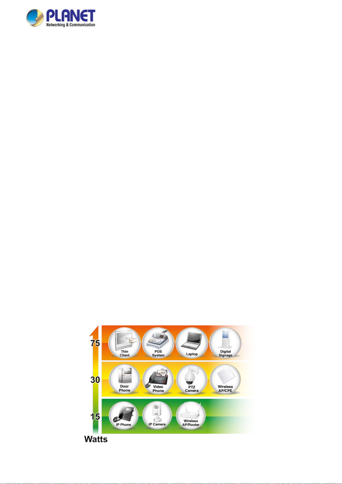
75 Watt s of Power over 4-pair UTP (For Ultra PoE Switches)
The GS-5220 Ultra PoE Series’ ultra PoE solut ion adopts the IEEE 802.3at/af standard. Instead of delivering power over 2-pair
twisted UTP – be it end-span (Pins 1,2,3 and 6) or mid-span (Pins 4,5,7 and 8), it provides the capability to source up to 75 watts
of power by using all the four pairs of standard Cat.5e/6 Ethernet cabling. In the new 4-pair system, two PSE controllers will be
used to power both the data pairs and the spare pairs. It can offer more PoE applications, such as:
■ PoE PTZ speed dome
■ Any network device that needs higher PoE power to work normally
■ Thin-client
■ AIO (All-in-One) touch PC
■ Remote digital signage display
Page 13
User’s Manual of GS-5220 Ultra PoE & PoE+ Series
13
Built-in Unique PoE Functions for Powered Devices Management
As it is the managed PoE switch for surveillance, wireless and VoIP networks, the GS-5220 Ultra PoE & PoE+ Series features
the following special PoE management functions:
PD alive check
Scheduled power recycling
PoE schedule
PoE usage monitoring
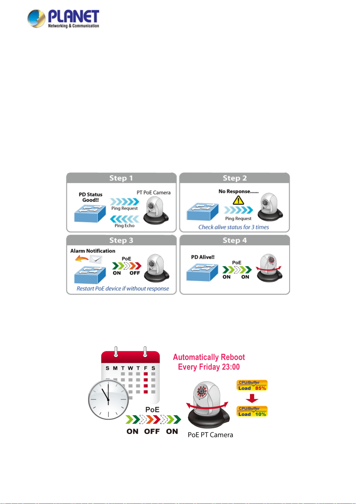
Intelligent Powered Device Alive Check
The GS-5220 Ultra PoE & PoE+ Series can be configured to monitor connected PD (powered device) status in real time via ping
action. Once the PD stops working and responding, the GS-5220 Ultra PoE & PoE+ Series will resume the PoE port power and
bring the PD back to work. It will greatly enhance the network reliability through the PoE port resetting the PD’s power source
and reducing administrator management burden.
Scheduled Power Recycling
The GS-5220 Ultra PoE & PoE+ Series allows each of the connected PoE IP cameras or PoE wireless access points to reboot
at a specified time each week. Therefore, it will reduce the chance of IP camera or AP crash resulting from buffer overflow.
Page 14
User’s Manual of GS-5220 Ultra PoE & PoE+ Series
14
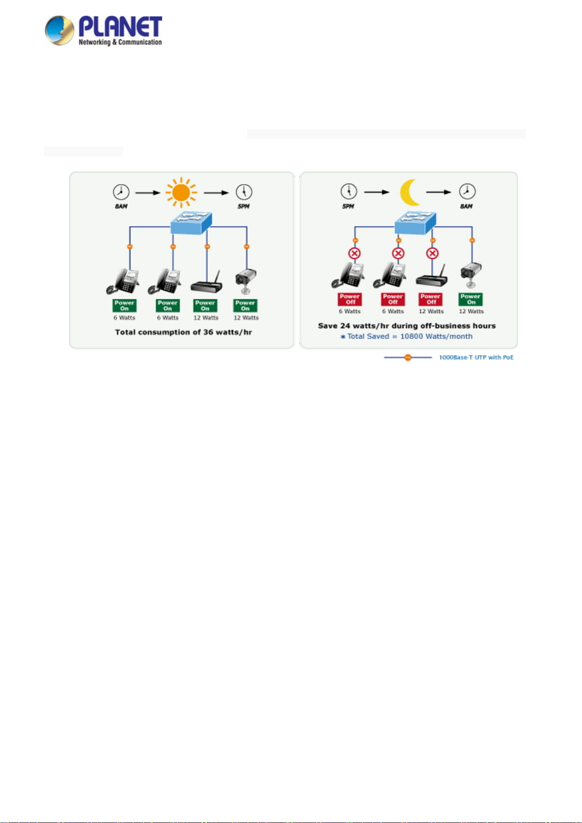
PoE Schedule for Energy Saving
Under the trend of energy saving worldwide and contributing to environmental protection, the GS-5220 Ultra PoE & PoE+ Series
can effectively control the power supply besides its capability of giving high watts power. The “PoE schedule” function helps
you to enable or disable PoE power feeding for each PoE port during specified time intervals and it is a powerful function to help
SMBs or enterprises save power and money. It also increases security by powering off PDs that should not be in use durin g
non-business hours.
PoE Usage Monitoring
Via the power usage chart in the web management interface, the GS-5220 Ultra PoE & PoE+ Series enables the administrator
to monitor the status of the power usage of the connected PDs in real time. Thus, it greatl y enhances the management
efficiency of the facilities.
Cost-effective 10Gbps Uplink Capacity
10G Ethernet is a big leap in the evolution of Ethernet. The four 10G SFP+ slots of the GS-5220 Ultra PoE & PoE+ Series
support dual-speed 10GBASE-SR/LR or 1000BASE-SX/LX, meaning the administrator now can f lexibly choose the suitable
SFP/SFP+ transceiver according to the trans mission distance or the transmission s peed required to extend the network
efficiently. They greatly support SM B network to achieve the maximum performance of 10Gbps in a cost-effective way because
the 10GbE interface usually c ould be available in Layer 3 Switch but La yer 3 Switch could be too expensive to SMBs.
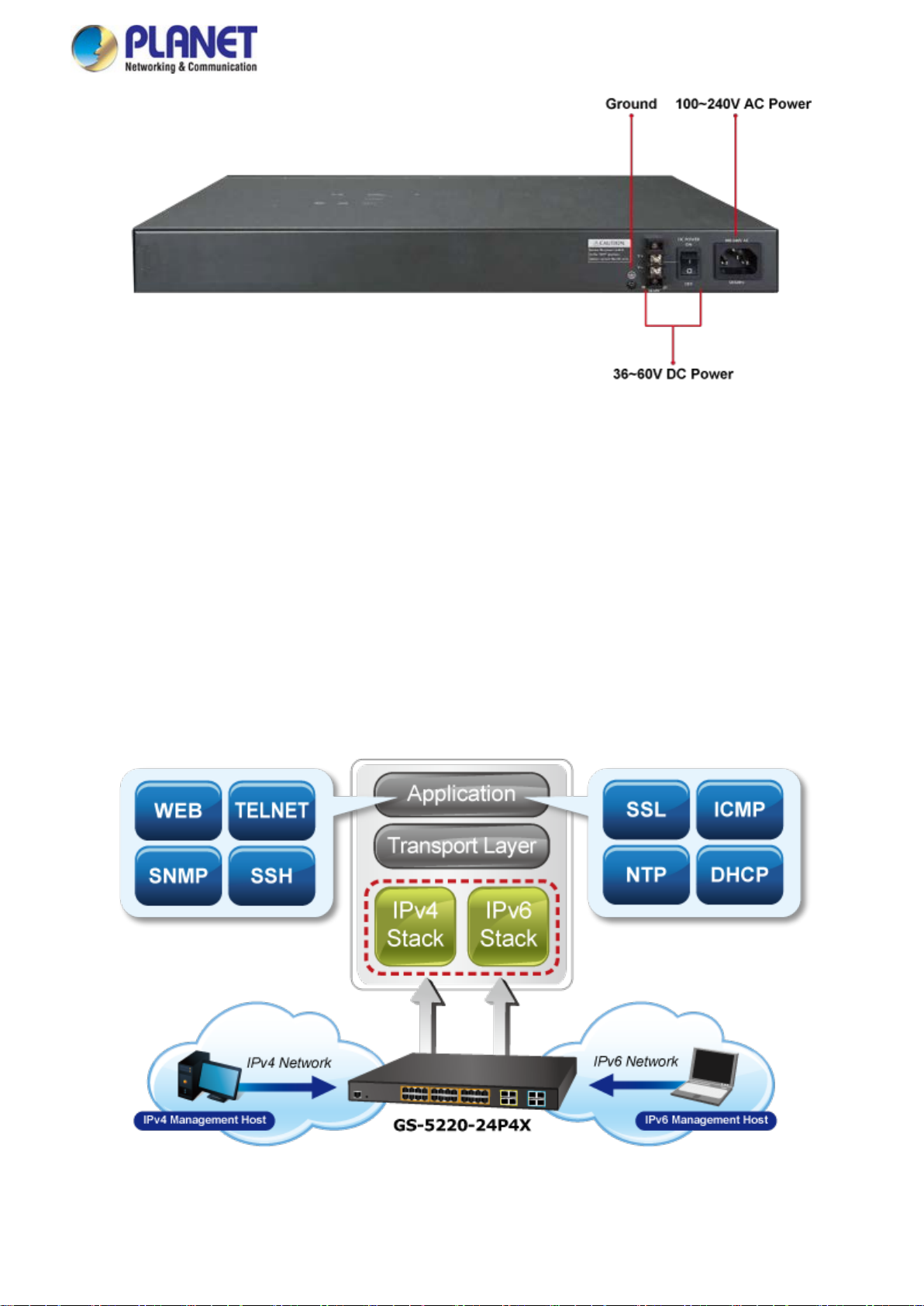
Redundant AC/DC Power Supply to Ensure Continuous Operation
The GS-5220 Ultra PoE & PoE+ Redundant Seri es is particularly equipped with one 100~240V AC power supply unit and one
36~60V DC power supply unit to provide an enh anced reliable and scalable redundant power supply. The continuous power
system is specifically designed to fulfill the demands of high-tech facilities requiring the highest power integrity. With the 36~60V
DC power supply, the GS-5220 Ultra PoE & PoE+ Redundant Series is able to act as a telecom-level device that can be located
in the electronic room. The DC power input is only for system which does not include PoE.
Page 15
User’s Manual of GS-5220 Ultra PoE & PoE+ Series
15
Environment-friendly, Smart Fan Design for Silent Operation
The GS-5220 Ultra PoE & PoE+ Series features a desktop-sized metal housing, a low no ise design and an effective ventilation
system. It supports the smart fan technology that automatically controls the speed of t he built-in fan to reduce noise and
maintain the temperature of the PoE switch for optimal power output capability . The GS-5220 Ultra PoE & PoE+ Series is able to
operate reliably, stably and quietly in any environment without affecting its performance.
Solution for IPv6 Networking
By supporting IPv6/IPv4 dual stack and pl enty of management functions with easy and user-friendly interfac es, the GS-5220
Ultra PoE & PoE+ Series is the best choice for IP surveillance, VoIP and wireless service providers to deploy the IPv6 network.
It also helps the SMBs to step in the IPv6 era with the lowest investment but it is not necessary to replace the network facilities
while the ISPs construct the IPv6 FTTx edge network.
Page 16
User’s Manual of GS-5220 Ultra PoE & PoE+ Series
16
IPv4 and IPv6 VLAN Routing for Secure and Flexible Managemen t
To help customers stay on top of their businesses, the GS-5220 Ultra PoE & PoE+ Series not onl y provides ultra high
transmission performance and excellent layer 2 technologies, but also offers IPv4/IPv6 VLAN routing feature which allows to
cross over different VLANs and different IP addresses for the purpose of having a highly-secure, flexible management and
simpler networking application.
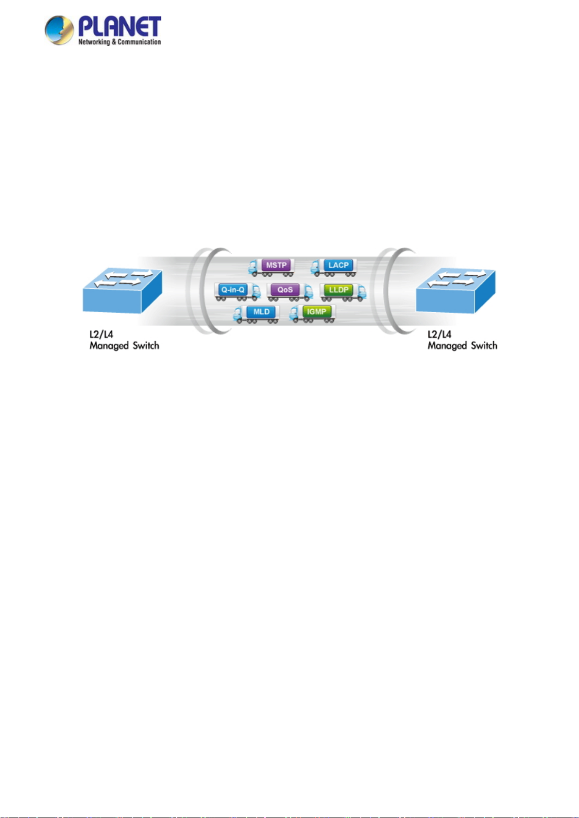
Robust Layer2 Features
The GS-5220 Ultra PoE & PoE+ Series can be programmed for advanced switch ma nagement function, such as dynamic port
link aggregation, Q-in-Q VLAN, Multiple Spanning Tree Protocol (MSTP), Layer 2/4 QoS, bandwidth control and IGMP/MLD
snooping. The GS-5220 Ultra PoE & PoE+ Series allows the operation of a hig h-s peed trunk combining multiple por ts. It
consists of a maximum of 14 trunk groups with 8 ports for each group, and suppor ts connection fail-over as well.
Powerful Security
The GS-5220 Ultra PoE & PoE+ Series offers a comprehensive La ye r 2 to Layer 4 access control list (ACL) for enforcing
security to the edge. It can be used to restr i ct to network access by denying packets based on source and destination IP
address, TCP/UDP port number or defined typical network applications. Its protection mec hanism also comprises 802.1x
Port-based and MAC-based user and device authentication. With the private VLAN function, com m unication between edge
ports can be prevented to ensure user privacy.
Enhanced Security and Traffic Control
The GS-5220 Ultra PoE & PoE+ Series also provides DHCP Snooping, IP Source Guard and Dynamic ARP Inspection
functions to prevent IP snooping from attack and discard ARP packets with invalid MAC address. The network administrator can
now construct highly-secure corporate networks with considerably less time and effort than before.
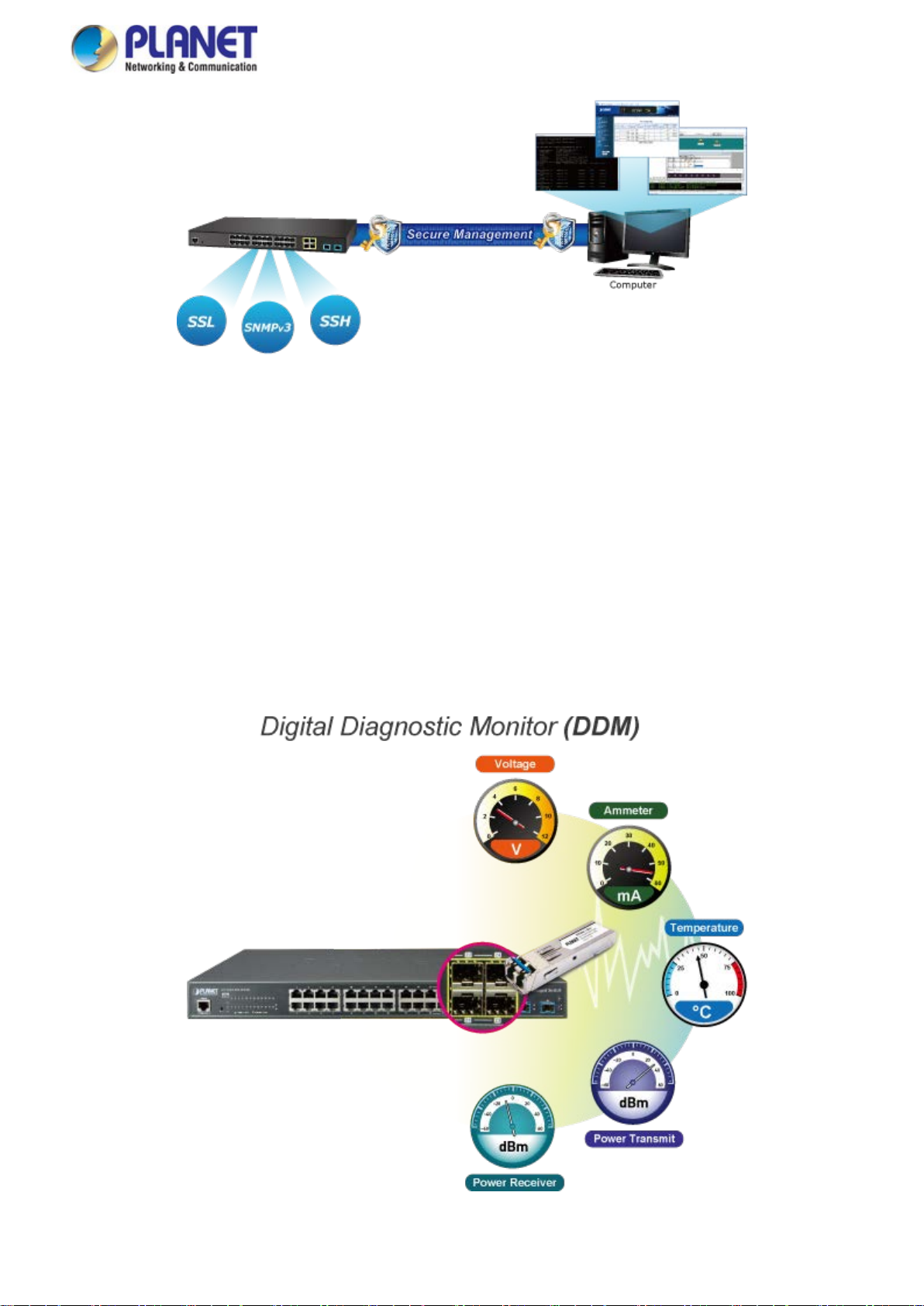
User-friendly Secure Management
For efficient management, the GS-5220 Ultra PoE & PoE+ Series is equipped with console, web and SNMP management
interfaces. With the built-in web-based management interface, the GS-5220 Ultra PoE & PoE+ Series offers an easy-to-use,
platform independent management and configuration facility. The GS-5220 Ultra PoE & PoE+ Series supports SNMP and it can
be managed via any management software based on the standard SNMP v1 or v2 Protocol. For reducing product learning time,
the GS-5220 Ultra PoE & PoE+ Series offers Cisco-like command via T elnet or console port and customer doesn’t need to learn
new command from these switches. M or eover, the GS-5220 Ultra PoE & PoE+ Series offers the remotely secure management
by supporting SSH, SSL and SNMPv3 connection where the packet content can be encrypted at each session.
Page 17
User’s Manual of GS-5220 Ultra PoE & PoE+ Series
17
Fl
exible and Extendable Solution
The 4 mini-GBIC SFP slots built in the GS-5220 Ultra PoE & PoE+ Series support dual speed as it features 100BASE-FX and
1000BASE-SX/LX SFP (Small Form-factor Pluggable) fiber-optic modules. Now the administrator can flexibly choose the
suitable SFP transceiver according to not only the transmission distance, but also the transmission speed required. The
distance can be extended from 550m to 2km (multi-mode fiber) and to 10/20/30/40/50/70/120 km (single-mode fiber or WDM
fiber). They are well suited for applications within the enterprise data centers and distr ibutions.
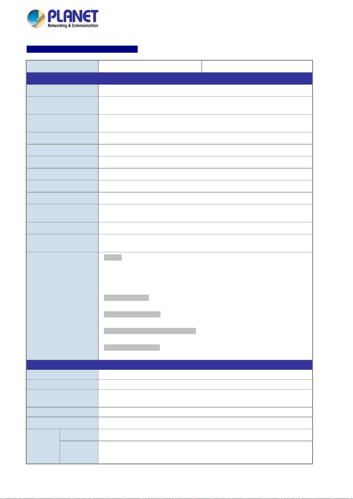
Intelligent SFP Diagnosis Mechanism
The GS-5220 Ultra PoE & PoE+ Series supports SFP-DDM (Digital Diagnostic Monitor) function that greatly helps network
administrator to easily monitor real-time parameters of the SFP and SFP+ transceivers, such as optical output power, optical
input power, temperature, laser bias current, and transcei v er supply voltage.
Page 18

User’s Manual of GS-5220 Ultra PoE & PoE+ Series
18
1.3 How to Use This Manual
This User’s Manual is structured as follows:
Section 2, INSTALLATION
The section explains the functions of the Managed Switch and how to physi c al ly install the Managed Switch.
Section 3, SWITCH MANAGEMENT
The section contains the information about the software function of the Managed Switch.
Section 4, WEB CONFIGURATION
The section explains how to manage the Managed Switch by Web interface.
Section 5, SWITCH OPERATION
The chapter explains how to do the switch operation of the Managed Switch.
Section 6, POWER over ETHERNET OVERVIEW
The chapter introduces the IEEE 802.3af / 802.3at PoE standard and PoE prov i s ion of the Managed Switch.
Section 7, TROUBLESHOOTING
The chapter explains how to do troubleshooting of the Managed Switch.
Appendix A
The section contains cable information of the Managed Switch.
Page 19

User’s Manual of GS-5220 Ultra PoE & PoE+ Series
19
1.4 Product Features
Physi cal Port
10/100/1000BASE-T Gigabit RJ45 copper
100/1000BASE-X mini-GBIC/SFP slots
1000BASE-X/10GBASE-X mini-GBIC/SFP+ slots
RJ45 console interface for switch basic management and setup
Power over Ethernet
Complies with IEEE 802.3at High Power over Ethernet end-span PSE
Complies with IEEE 802.3af Power over Ethernet end-span PSE
Up to 16/24 ports of IEEE 802.3af/802.3at devices powered
Supports PoE Power up to 30.8 watts for each PoE port (GS-5220-24P4X/R and GS-5220-24PL4X/R)
Supports PoE power up to 36 watts for each PoE port (GS-5220-48P 4X/R and GS-5220-48PL4X/R)
Supports PoE Power up to 75 watts for each PoE port (GS-5220-16UP4S2X/R, 24UP4X/R and GS-5220-24UPL4X/R)
Auto detects powered device (PD)
Circuit protection prevents power inter ference between ports
Remote power feeding up to 100 meters
PoE Management
− Total PoE power budget control
− Per port PoE function enable/disable
− PoE Port Power feeding priority
− Per PoE port power limitation
− PD classification detection
− PD alive check
− PoE schedule
− PD power recycling schedule
Layer 2 Features
Prevents packet loss with back pressure (half-duplex) and IEEE 802.3x pause frame flow control (full-duplex)
High performance of Store-and-Forward architecture, and runt/CRC filtering eliminates erroneous packets to optimize
the network bandwidth
Storm Control support
− Broadcast/Unicast/Unknown-unicast
Supports VLAN
− IEEE 802.1Q tagged VLAN
− Up to 255 VLANs groups, out of 4094 VLAN IDs
− Provider Bridging (VLAN Q-in-Q) support (IEEE 802.1ad)
− Private VLAN Edge (PVE)
− Protocol-based VLAN
− MAC-based VLAN
Page 20

20
− IP Subnet-based VLAN
− Voice VLAN
Supports Spanning Tree Protocol
− STP, IEEE 802.1D Sp anning T ree Protocol
− RSTP, IEEE 802.1w Rapid Spanning Tree Protocol
− MSTP, IEEE 802.1s Multiple Spanning Tree Protocol, spanning tree by VLAN
− BPDU Guard
Supports Link Aggregation
− 802.3ad Link Aggregation Control Protocol (LACP)
− Cisco ether-channel (Static Trunk)
(GS-5220-24P4X/R, GS-5220-24PL4X/R, GS-5220-24UP4X/R and GS-5220-24UPL4X/R)
− Maximum 14 trunk groups, up to 8 ports per trunk group
− Up to 16Gbps bandwidth (full duplex mode)
(GS-5220-16UP4S2X and GS-5220-16UP4S2XR)
− Maximum 11 trunk groups, up to 6 ports per trunk group
− Up to 12Gbps bandwidth (full duplex mode)
(GS-5220-48P4X/R and GS-5220-48PL4X/R)
− Maximum 26 trunk groups with 4 ports f or each trunk group
− Up to 80Gbps bandwidth (full duplex mode)
User’s Manual of GS-5220 Ultra PoE & PoE+ Series
Provides port mirror (many-to-1)
Port mirroring to monitor the incoming or outgoing traffic on a particular port
Loop protection to avoid broadcast loops
Layer 3 IP Routing Features
Supports maximum 32 static routes and rout e s ummarization
Quality of Service
Ingress Shaper and Egress Rate Limit per port bandwidth control
8 priority queues on all switch ports
Traffic classification
- IEEE 802.1p CoS
- TOS/DSCP/IP Precedence of IPv4/IPv6 packets
- IP TCP/UDP port number
- Typical network application
Strict priority and Weighted Round Robin (WRR) CoS policies
Traffic-policing policies on the s witch port
DSCP remarking
Multicast
Supports IGMP Snooping v1, v2 and v3
Supports MLD Snooping v1 and v2
Querier mode support
IGMP Snooping port filtering
Page 21

User’s Manual of GS-5220 Ultra PoE & PoE+ Series
21
MLD Snooping port filtering
MVR (Multicast VLAN Registration)
Security
Authentication
- IEEE 802.1x Port-based/MAC-based network ac cess authentication
- IEEE 802.1x Authentication with Guest VLAN
- Built-in RADIUS client to cooperate with the RADIUS servers
- RADIUS/TACACS+ users access authentication
Access Control List
- IP-based Access Control List (ACL)
- MAC-based Access Control List (ACL)
Source MAC/IP address binding
DHCP Snooping to filter distrusted DHCP messages
Dynamic ARP Inspection discards ARP packets with invalid MAC address to IP address binding
IP Source Guard prevents IP spoofing attacks
IP address access management to prevent una uthorized intruder
Management
IPv4 and IPv6 dual stack management
Switch Management Interfaces
- Console/Telnet Command Line Interface
- Web switch management
- SNMP v1, v2c, and v3 switch management
- SSH/SSL secure access
IPv6 Address/NTP management
Built-in Trivial File Transfer Protocol (TFTP) client
BOOTP and DHCP for IP address assignment
System Maintenance
- Firmware upload/download via HTTP/TFTP
- Reset button for system reboot or reset to factory default
- Dual Images
DHCP Relay and Option 82
User Privilege levels control
NTP (Network Time Protocol)
Link Layer Discovery Protocol (LLDP) and LLDP-MED
Network Diagnostic
- SFP-DDM (Digital Diagnostic Monitor)
- Cable Diagnostic technology prov ides the mechanism to detect and report potential cabling issues
- ICMPv6/ICMPv4 Remote Ping
SMTP/Syslog remote alarm
Four RMON groups (history, statistics, alarms and events)
Page 22

User’s Manual of GS-5220 Ultra PoE & PoE+ Series
22
SNMP trap for interface Link Up and Link Down noti fication
System Log
PLANET Smart Discovery Utility for deploy management
Redundant Power System (GS-5220-24P4XR, 24PL4XR, 16UP4S2XR, 24UP4XR, 24UPL4XR, 48P4XR and 48PL4XR)
■ 100~240V AC/36-60V DC Dual power redundant
■ Active-active redundant power failure protection
■ Backup of catastrophic power failure on one supply
■ Fault tolerance and resilience.
Page 23
User’s Manual of GS-5220 Ultra PoE & PoE+ Series
23
Ability
Power Pin Assignment
1.5 Product Specifications
GS-5220-24P4X and GS-5220-24P4XR
Product GS-5220-24P4X GS-5220-24P4XR
Hardware Specifications
Copper Ports
SFP/mini-GBIC Slots
10Gbps Fiber Uplink Ports
Console
Switch Architecture
Switch Fabric
Throughput
Address Table
Shared Data Buffer
Flow Control
Jumbo Frame
Reset Button
LED
Power over Ethernet
PoE Standard
PoE Power Supply Type
PoE Port Power Output
24 10/100/1000BASE-T RJ45 auto-MDI/MDI-X ports with IEEE 802.3at PoE injector
4 100/1000BASE-X SFP combo interfaces with Port -21 to Port-24
Supports 100/1000Mbps dual mode and DDM
4 1/10GBASE-SR/LR SFP+ slots
Supports 1/10Gbps dual mode and DDM
1 RJ45 serial port (115200, 8, N, 1)
Store-and-Forward
128Gbps/non-blocking
95 Mpps@64 bytes
16K entries, automatic source address learning and aging
32M bytes
IEEE 802.3x pause frame for full-duplex
Back pressure for half-duplex
10K bytes
< 5 sec: System reboot
> 5 sec: Factory default
System:
SYS (Green)
PWR (Green) (GS-5220-24P4XR showed AC)
DC (Green) (GS-5220-24P4XR Only)
FAN1 (Red), FAN2 (Red), FAN3 (Red), PoE PWR (Red)
Ethernet Interfaces (Port 1 to Port 24):
1000 LNK/ACT (Green), 10/100 LNK/ACT (Orange)
PoE Ethernet Interfaces (Port 1 to Port 24):
PoE-in-Use (af/at-Orange)
100/1000Mbps SFP Combo Interfaces (Port-21 to Port-24):
1000 (Green), 100 (Orange)
1/10G SFP+ Interfaces (Port-25 to Port-28):
1000 (Green), 10G (Orange)
IEEE 802.3at PoE Plus PSE
End-span
Max. 36 watts
PoE Power Budget
PoE Ability
PD @ 7 watts
PD @ 15.4
watts
1/2(-), 3/6(+)
400 watts max.
24 units
24 units
Page 24
User’s Manual of GS-5220 Ultra PoE & PoE+ Series
24
Flow control disable/enable
10 groups of 16-port trunk supported
Up to 256 entries
PD @ 30.8
watts
Power Requirements
Power Consumption (Full
Loading)
ESD Protection 6KV DC
Dimensions (W x D x H)
Enclosure
Fan
Weight
Layer 2 Function
Port Configuration
12 units
100~240V AC, 50/60Hz, 7A 100-240V AC, 50/60Hz, 7A
AC 110V:
Max. 26.7 watts/91.6BTU (Power on without any connection)
Max. 447 watts/1533.6BTU (Full loading with PoE function)
AC 220V:
Max. 27.7 watts/95.03BTU (Power on without any connection)
Max. 452 watts/1550.8BTU (Full loading with PoE function)
440 x 300 x 44.5 mm, 1U height
Metal
3 x smart fan
4546g (GS-5220-24P4X) 4570g (GS-5220-24P4XR)
Port disable/enable
Auto-negotiation 10/100/1000M bps full or half duplex mode selection
48V DC @ 2A, Range: 36 ~ 60V
Port Status
Port Mirroring
VLAN
Link Aggregation
QoS
IGMP Snooping
MLD Snooping
Access Control List
Display each port’s speed duplex mode, link status, flow control status, auto-negotiation
status, trunk status
TX/RX/Both
Many-to-1 monitor
802.1Q tagged-based VLAN, up to 256 VLAN groups
Q-in-Q tunneling
Private VLAN edge (PVE)
MAC-based VLAN
Protocol-based VLAN
Voice VLAN
IP Subnet-based VLAN
MVR (Multicast VLAN registration)
Up to 256 VLAN groups, out of 4094 VLAN IDs
IEEE 802.3ad LACP/static trunk
Traffic classification based, strict priority and WRR
8-level priority for switching
- Port number
- 802.1p priority
- 802.1Q VLAN tag
- DSCP field in IP packet
IGMP (v1/v2/v3) snooping, up to 255 multicast groups
IGMP querier mode support
MLD (v1/v2) snooping, up to 255 multicast groups
MLD querier mode support
IP-based ACL / MAC-based ACL
Page 25

25
MAU MIB
Standards Conformance
FRC 3810 MLD v2
Layer 3 Function
User’s Manual of GS-5220 Ultra PoE & PoE+ Series
IP Interfaces
Routing Table
Routing Protocols
Management
Basic Management
Interfaces
Secure Management
Interfaces
SNMP MIBs
Max. 8 VLAN interfaces
Max. 32 routing entries
IPv4 software static routing
IPv6 software static routing
Console, Telnet, Web browser, and SNMP v1/v2c
SSH/SSL, SNMP v3
RFC 1213 MIB-II
IF MIB
RFC 1493 Bridge MIB
RFC 1643 Ethernet MIB
RFC 2863 Interface MIB
RFC 2665 Ether-Like MIB
RFC 2819 RMON MIB (Groups 1 and 2)
RFC 2737 Entity MIB
RFC 2618 RADIUS Client MIB
RFC 3411 SNMP-Frameworks-MIB
IEEE 802.1x PAE
LLDP
Regulatory Compliance
Standards Compliance
FCC Part 15 Class A, CE
IEEE 802.3 10BASE-T
IEEE 802.3u 100BASE-TX/100BASE-FX
IEEE 802.3z Gigabit SX/LX
IEEE 802.3ab Gigabit 1000T
IEEE 802.3ae 10Gb/s Ethernet
IEEE 802.3x flow control and back pressure
IEEE 802.3ad port trunk with LACP
IEEE 802.1D Spanning Tree Protocol
IEEE 802.1w Rapid Spanning Tree Protocol
IEEE 802.1s Multiple Spanning Tree Protocol
IEEE 802.1p Class of service
IEEE 802.1Q VLAN tagging
IEEE 802.1x port authentication network control
IEEE 802.3af Power over Ethernet
IEEE 802.3at Power over Ethernet Plus
IEEE 802.1ab LLDP
RFC 768 UDP
RFC 793 TFTP
RFC 791 IP
RFC 792 ICMP
RFC 2068 HTTP
RFC 1112 IGMP v1
RFC 2236 IGMP v2
RFC 3376 IGMP v3
RFC 2710 MLD v1
Page 26
User’s Manual of GS-5220 Ultra PoE & PoE+ Series
26
Environment
Relative Humidity: 5 ~ 95% (non-condensing)
1000 (Green), 10G (Orange)
Ability
Operating
Storage
Temperature: 0 ~ 50 degrees C
Relative Humidity: 5 ~ 95% (non-condensing)
Temperature: -10 ~ 70 degrees C
GS-5220-24PL4X and GS-5220-24PL4XR
Product GS-5220-24PL4X GS-5220-24PL4XR
Hardware Specifications
Copper Ports
SFP/mini-GBIC Slots
10Gbps Fiber Uplink Ports
Console
Switch Architecture
Switch Fabric
Throughput
Address Table
Shared Data Buffer
Flow Control
Jumbo Frame
Reset Button
LED
24 10/100/1000BASE-T RJ45 auto-MDI/MDI-X ports with IEEE 802.3at PoE injector
4 100/1000BASE-X SFP combo interfaces with Port -21 to Port-24
Supports 100/1000Mbps dual mode and DDM
4 1/10GBASE-SR/LR SFP+ slots
Supports 1/10Gbps dual mode and DDM
1 RJ45 serial port (115200, 8, N, 1)
Store-and-Forward
128Gbps/non-blocking
95 Mpps@64 bytes
16K entries, automatic source address learning and aging
32M bytes
IEEE 802.3x pause frame for full-duplex
Back pressure for half-duplex
10K bytes
< 5 sec: System reboot
> 5 sec: Factory default
System:
SYS (Green)
PWR (Green) (GS-5220-24PL4XR showed AC)
DC (Green) (GS-5220-24PL4XR Only)
FAN1 (Red), FAN2 (Red), FAN3 (Red), PoE PWR (Red)
Ethernet Interfaces (Port 1 to Port 24):
1000 LNK/ACT (Green), 10/100 LNK/ACT (Orange)
PoE Ethernet Interfaces (Port 1 to Port 24):
PoE-in-Use (af/at-Orange)
100/1000Mbps SFP Combo Interfaces (Port-21 to Port-24):
1000 (Green), 100 (Orange)
1/10G SFP+ Interfaces (Port-25 to Port-28):
Power over Ethernet
PoE Standard
PoE Power Supply Type
PoE Port Power Output
IEEE 802.3at PoE Plus PSE
End-span
Max. 36 watts
Page 27

27
48V DC @ 2A, Range: 36 ~ 60V
thout
Flow control disable/enable
10 groups of 16-port trunk supported
Power Pin Assignment 1/2(-), 3/6(+)
User’s Manual of GS-5220 Ultra PoE & PoE+ Series
PoE Power Budget
PD @ 7 watts
PD @ 15.4
PoE Ability
Power Requirements
Power Consumption (Full
Loading)
ESD Protection 6KV DC
Dimensions (W x D x H)
Enclosure
Fan
watts
PD @ 30.8
watts
600 watts max.
24 units
24 units
20 units
100~240V AC, 50/60Hz, 10A 100-240V AC, 50/60Hz, 10A
AC 110V:
Max. 45.8 watts/157.1BTU (Power on
without any connection)
Max. 657.9 watts/2257.2BTU (Full loading
with PoE function)
440 x 300 x 44.5 mm, 1U height
Metal
3 x smart fan
AC 220V:
Max. 45.5 watts/198.6BTU (Power on wi
any connection)
Max. 660.3 watts/2265.5BTU (Full loading
with PoE function)
Weight
Layer 2 Function
Port Configuration
Port Status
Port Mirroring
VLAN
Link Aggregation
5040g (GS-5220-24PL4X) 5071g (GS-5220-24PL4XR)
Port disable/enable
Auto-negotiation 10/100/1000M bps full or half duplex mode selection
Display each port’s speed duplex mode, link status, flow control status, auto-negotiation
status, trunk status
TX/RX/Both
Many-to-1 monitor
802.1Q tagged-based VLAN, up to 256 VLAN groups
Q-in-Q tunneling
Private VLAN edge (PVE)
MAC-based VLAN
Protocol-based VLAN
Voice VLAN
IP Subnet-based VLAN
MVR (Multicast VLAN registration)
Up to 256 VLAN groups, out of 4094 VLAN IDs
IEEE 802.3ad LACP/static trunk
QoS
IGMP Snooping
Traffic classification based, strict priority and WRR
8-level priority for switching
- Port number
- 802.1p priority
- 802.1Q VLAN tag
- DSCP field in IP packet
IGMP (v1/v2/v3) snooping, up to 255 multicast groups
Page 28

28
MAU MIB
Standards Conformance
RFC 793 TFTP
MLD Snooping
Access Control List
Layer 3 Function
User’s Manual of GS-5220 Ultra PoE & PoE+ Series
IGMP querier mode support
MLD (v1/v2) snooping, up to 255 multicast groups
MLD querier mode support
IP-based ACL / MAC-based ACL
Up to 256 entries
IP Interfaces
Routing Table
Routing Protocols
Management
Basic Management
Interfaces
Secure Management
Interfaces
ONVIF
SNMP MIBs
Max. 8 VLAN interfaces
Max. 32 routing entries
IPv4 software static routing
IPv6 software static routing
Console, Telnet, Web browser, and SNMP v1/v2c
SSH/SSL, SNMP v3
ONVIF device discovery
ONVIF device monitoring
Floor map
RFC 1213 MIB-II
IF MIB
RFC 1493 Bridge MIB
RFC 1643 Ethernet MIB
RFC 2863 Interface MIB
RFC 2665 Ether-Like MIB
RFC 2819 RMON MIB (Groups 1 and 2)
RFC 2737 Entity MIB
RFC 2618 RADIUS Client MIB
RFC 3411 SNMP-Frameworks-MIB
IEEE 802.1x PAE
LLDP
Regulatory Compliance
Standards Compliance
FCC Part 15 Class A, CE
IEEE 802.3 10BASE-T
IEEE 802.3u 100BASE-TX/100BASE-FX
IEEE 802.3z Gigabit SX/LX
IEEE 802.3ab Gigabit 1000T
IEEE 802.3ae 10Gb/s Ethernet
IEEE 802.3x flow control and back pressure
IEEE 802.3ad port trunk with LACP
IEEE 802.1D Spanning Tree Protocol
IEEE 802.1w Rapid Spanning Tree Protocol
IEEE 802.1s Multiple Spanning Tree Protocol
IEEE 802.1p Class of service
IEEE 802.1Q VLAN tagging
IEEE 802.1x port authentication network control
IEEE 802.3af Power over Ethernet
IEEE 802.3at Power over Ethernet Plus
IEEE 802.1ab LLDP
RFC 768 UDP
Page 29
User’s Manual of GS-5220 Ultra PoE & PoE+ Series
29
Environment
Relative Humidity: 5 ~ 95% (non-condensing)
Hardware Specifications
Copper Ports
Console
Switch Architecture
Throughput
Address Table
Shared Data Buffer
Jumbo Frame
> 5 sec: Factory default
Dimensions (W x D x H)
RFC 791 IP
RFC 792 ICMP
RFC 2068 HTTP
RFC 1112 IGMP v1
RFC 2236 IGMP v2
RFC 3376 IGMP v3
RFC 2710 MLD v1
FRC 3810 MLD v2
Operating
Storage
Temperature: 0 ~ 50 degrees C for AC power input
Temperature: -40 ~ 80 degrees C
Relative Humidity: 5 ~ 95% (non-condensing)
GS-5220-16UP4S2X and GS-5220-16UP4S2XR
Product
SFP/mini-GBIC Slots
SFP+ Slots
Switch Fabric
Flow Control
Reset Button
GS-5220-16UP4S2X and GS-5220-16UP4S2XR
16 10/100/1000BASE-T RJ45 auto-MDI/MDI-X ports
4 100/1000BASE-X SFP interfaces,
Compatible with 100BASE-FX SFP transceiver
2 10GbBASE-SR/LR SFP+ interfaces (Port-21 to Port-22)
Compatible with 1000BASE-SX/LX/BX SFP transceiver
1 x RS232-to-RJ45 serial port (115200, 8, N, 1)
Store-and-Forward
80Gbps/non-blocking
59.52Mpps@64Bytes
16K entries, automatic source address learning and aging
32M bits
IEEE 802.3x pause frame for full-duplex
Back pressure for half-duplex
10K bytes
< 5 sec: System reboot
Weight
LED
440 x 300 x 44.5 mm, 1U height
4466g (GS-5220-16UP4S2X)
4503g (GS-5220-16UP4S2XR)
System:
SYS (Green)
AC/PWR (Green)
DC (Green) (GS-5220-16UP4S2XR Only)
Fan1/2/3 Alert (Red)
PoE PWR Alert (Red)
PoE Ethernet Interfaces (Port 1 to Port 16):
PoE-in-Use (bt-Green) (af/at- Orange)
Ethernet Interfaces (Port 1 to Port 16):
1000 LNK/ACT (Green), 10/100 LNK/ACT (Orange)
100/1000Mbps SFP Interfaces (Port 17 to Port 20):
1000 (Green), 100 (Orange)
1/10G SFP+ Interfaces (Port 21 to Port 22):
Page 30

User’s Manual of GS-5220 Ultra PoE & PoE+ Series
30
Fan
PoE Standard
PoE Power Supply Type
PoE Power Output
PoE Ability PD @ 15 watts
PoE Ability PD @ 30 watts
Layer 2 Management Functions
Flow control disable/enable
11 groups with 6 port per trunk
1000 (Green), 10G (Orange)
Power Consumption
Power Requirements – AC
Power Requirements – DC
ESD Protection
Power over Ethernet
Power Pin Assignment
PoE Power Budget
PoE Ability PD @ 60 watts
Port Configuration
Max. 439.4 watts/1498.3 BTU
AC 100~240V, 50/60Hz, 7A
DC 36~60V, 2A (GS-5220-16UP4S2X)
6KV DC
3 smart fan
IEEE 802.3af/802.3at/802.3bt Ultra PoE PSE
End-span/Mid-span/UPoE
Per port 54V DC, 75 watts (max.)
End-span: 1/2(-), 3/6(+)
Mid-span: 4/5(+), 7/8(-)
UPoE: 1/2(-), 3/6(+),4/5(+), 7/8(-)
400 watts (max.)
24 units
13 units
6 units
Port disable/enable
Auto-negotiation 10/100/1000Mbps full and half duplex mode selection
Port Status
Port Mirroring
VLAN
Link Aggregation
Spanning Tree Protocol
QoS
IGMP Snooping
Display each port’s speed duplex mode, link status, flow control status,
auto-negotiation status, trunk status
TX/RX/Both
Many-to-1 monitor
802.1Q tagged based VLAN
Q-in-Q tunneling
Private VLAN Edge (PVE)
MAC-based VLAN
Protocol-based VLAN
Voice VLAN
IP subnet-based VLAN
MVR (Multicast VLAN registration)
Up to 255 VLAN groups, out of 4095 VLAN IDs
IEEE 802.3ad LACP/static trunk
IEEE 802.1D Spanning Tree Protocol (STP)
IEEE 802.1w Rapid Spanning Tree Protocol (RSTP)
IEEE 802.1s Multiple Spanning Tree Protocol (MSTP)
Traffic classification based, strict priority and WRR
8-level priority for switching:
- Port number
- 802.1p priority
- 802.1Q VLAN tag
- DSCP/ToS field in IP packet
IGMP (v1/v2/v3) snooping, up to 255 multicast groups
IGMP querier mode support
Page 31

User’s Manual of GS-5220 Ultra PoE & PoE+ Series
31
Management
Secure Management Interfaces
LLDP
Regulatory Compliance
MLD Snooping
Access Control List
Bandwidth Control
Layer 3 Functions
IP Interfaces Max. 8 VLAN interfaces
Routing Table Max. 32 routing entries
Routing Protocols
Basic Management Interfaces Console; Telnet; Web browser; SNMP v1, v2c
ONVIF
SNMP MIBs
MLD (v1/v2) snooping, up to 255 multicast groups
MLD querier mode support
IP-based ACL/MAC-based ACL
Up to 256 entries
Per port bandwidth control
Ingress: 100Kbps~1000Mbps
Egress: 100Kbps~1000Mbps
IPv4 software static routing
IPv6 software static routing
SSH, SSL, SNMP v3
ONVIF device discovery
ONVIF device monitoring
Floor map
RFC 1213 MIB-II
RFC 1493 Bridge MIB
RFC 1643 Ethernet MIB
RFC 2863 Interface MIB
RFC 2665 Ether-Like MIB
RFC 2819 RMON MIB (Groups 1, 2, 3
and 9)
RFC 2737 Entity MIB
RFC 2618 RADIUS Client MIB
RFC 2863 IF-MIB
RFC 2933 IGMP-STD-MIB
RFC 3411 SNMP-Frameworks-MIB
RFC 4292 IP Forward MIB
RFC 4293 IP MIB
RFC 4836 MAU-MIB
IEEE 802.1X PAE
Standards Conformance
Standards Compliance
FCC Part 15 Class A, CE
IEEE 802.3 10BASE-T
IEEE 802.3u 100BASE-TX/100BASE-FX
IEEE 802.3z Gigabit SX/LX
IEEE 802.3ab Gigabit 1000T
IEEE 802.3ae 10Gb/s Ethernet
IEEE 802.3x flow control and back
pressure
IEEE 802.3ad port trunk with LACP
IEEE 802.1D Spanning Tree Protocol
IEEE 802.1w Rapid Spanning Tree
Protocol
IEEE 802.1s Multiple Spanning Tree
Protocol
IEEE 802.1p Class of Service
IEEE 802.1Q VLAN tagging
IEEE 802.1x Port Authentication Network
Control
IEEE 802.1ab LLDP
IEEE 802.3af Power over Ethernet
IEEE 802.3at Power over Ethernet Plus
IEEE 802.3bt 4-pair Power over Ethernet
RFC 768 UDP
RFC 793 TFTP
RFC 791 IP
RFC 792 ICMP
RFC 2068 HTTP
RFC 1112 IGMP v1
RFC 2236 IGMP v2
RFC 3376 IGMP v3
RFC 2710 MLD v1
FRC 3810 MLD v2
Page 32

32
Hardware Specifications
Compatible with 1000BASE-SX/LX/BX SFP transceiver
Console
Throughput
Address Table
Jumbo Frame
> 5 sec: Factory default
ESD Protection
Fan
Environment
Operating
Storage
Temperature: 0 ~ 50 degrees C for AC power input
Relative Humidity: 5 ~ 95% (non-condensing)
Temperature: -40 ~ 80 degrees C
Relative Humidity: 5 ~ 95% (non-condensing)
GS-5220-24UP4X and GS-5220-24UP4XR
User’s Manual of GS-5220 Ultra PoE & PoE+ Series
Product
Copper Ports
SFP/mini-GBIC Slots
SFP+ Slots
Switch Architecture
Switch Fabric
Shared Data Buffer
Flow Control
Reset Button
Dimensions (W x D x H)
Weight
LED
GS-5220-24UP4X and GS-5220-24UP4XR
24 10/100/1000BASE-T RJ45 auto-MDI/MDI-X ports
4 100/1000BASE-X SFP interfaces, shared with Port-21 to Port-24
Compatible with 100BASE-FX SFP transceiver
4 10GbBASE-SR/LR SFP+ interfaces (Port-25 to Port-28)
1 x RS232-to-RJ45 serial port (115200, 8, N, 1)
Store-and-Forward
128Gbps/non-blocking
95.23Mpps@64Bytes
16K entries, automatic source address learning and aging
32M bits
IEEE 802.3x pause frame for full-duplex
Back pressure for half-duplex
10K bytes
< 5 sec: System reboot
440 x 300 x 44.5 mm, 1U height
4551g (GS-5220-24UP4X)
4588g (GS-5220-24UP4XR)
System:
SYS (Green)
AC/PWR (Green)
DC (Green) (GS-5220-24UP4XR Only)
Fan1/2/3 Alert (Red)
PoE PWR Alert (Red)
PoE Ethernet Interfaces (Port 1 to Port 24):
PoE-in-Use (bt-Green) (af/at- Orange)
Ethernet Interfaces (Port 1 to Port 24) :
1000 LNK/ACT (Green), 10/100 LNK/ACT (Orange)
100/1000Mbps SFP Combo Interfaces (Port 21 to Port 24) :
1000 (Green), 100 (Orange)
1/10G SFP+ Interfaces (Port 25 to Port 28) :
1000 (Green), 10G (Orange)
Power Consumption
Power Requirements – AC
Power Requirements – DC
Max. 446.6 watts/1522.9 BTU
AC 100~240V, 50/60Hz, 7A
DC 36~60V, 2A (GS-5220-24UP4XR)
6KV DC
3 smart fan
Page 33

33
Power over Ethernet
PoE Standard
UPoE: 1/2(-), 3/6(+),4/5(+), 7/8(-)
PoE Power Budget
PoE Ability PD @ 30 watts
PoE Ability PD @ 60 watts
Many-to-1 monitor
- DSCP/ToS field in IP packet
Egress: 100Kbps~1000Mbps
PoE Power Supply Type
PoE Power Output
Power Pin Assignment
PoE Ability PD @ 15 watts
Layer 2 Management Functions
Port Configuration
Port Status
Port Mirroring
User’s Manual of GS-5220 Ultra PoE & PoE+ Series
IEEE 802.3af/802.3at/802.3bt Ultra PoE PSE
End-span/Mid-span/UPoE
Per port 54V DC, 75 watts (max.)
End-span: 1/2(-), 3/6(+)
Mid-span: 4/5(+), 7/8(-)
400 watts (max.)
24 units
13 units
6 units
Port disable/enable
Auto-negotiation 10/100/1000M bps full and half duplex mode selection
Flow control disable/enable
Display each port’s speed duplex mode, link status, flow control status,
auto-negotiation status, trunk status
TX/RX/Both
VLAN
Link Aggregation
Spanning Tree Protocol
QoS
IGMP Snooping
MLD Snooping
Access Control List
Bandwidth Control
802.1Q tagged based VLAN
Q-in-Q tunneling
Private VLAN Edge (PVE)
MAC-based VLAN
Protocol-based VLAN
Voice VLAN
IP subnet-based VLAN
MVR (Multicast VLAN registration)
Up to 255 VLAN groups, out of 4095 VLAN IDs
IEEE 802.3ad LACP/static trunk
14 groups with 8 port per trunk
IEEE 802.1D Spanning Tree Protocol (STP)
IEEE 802.1w Rapid Spanning Tree Protocol (RSTP)
IEEE 802.1s Multiple Spanning Tree Protocol (MSTP)
Traffic classification based, strict priority and WRR
8-level priority for switching:
- Port number
- 802.1p priority
- 802.1Q VLAN tag
IGMP (v1/v2/v3) snooping, up to 255 multicast groups
IGMP querier mode support
MLD (v1/v2) snooping, up to 255 multicast groups
MLD querier mode support
IP-based ACL/MAC-based ACL
Up to 256 entries
Per port bandwidth control
Ingress: 100Kbps~1000Mbps
Page 34

34
Basic Management Interfaces
Secure Management Interfaces
Floor map
Standards Conformance
Regulatory Compliance
FRC 3810 MLD v2
Layer 3 Functions
IP Interfaces Max. 8 VLAN interfaces
Routing Table Max. 32 routing entries
User’s Manual of GS-5220 Ultra PoE & PoE+ Series
Routing Protocols
Management
ONVIF
SNMP MIBs
Standards Compliance
IPv4 software static routing
IPv6 software static routing
Console; Telnet; Web browser; SNMP v1, v2c
SSH, SSL, SNMP v3
ONVIF device discovery
ONVIF device monitoring
RFC 1213 MIB-II
RFC 1493 Bridge MIB
RFC 1643 Ethernet MIB
RFC 2863 Interface MIB
RFC 2665 Ether-Like MIB
RFC 2819 RMON MIB (Groups 1, 2, 3
and 9)
RFC 2737 Entity MIB
FCC Part 15 Class A, CE
IEEE 802.3 10BASE-T
IEEE 802.3u 100BASE-TX/100BASE-FX
IEEE 802.3z Gigabit SX/LX
IEEE 802.3ab Gigabit 1000T
IEEE 802.3ae 10Gb/s Ethernet
IEEE 802.3x flow control and back
pressure
IEEE 802.3ad port trunk with LACP
IEEE 802.1D Spanning Tree Protocol
IEEE 802.1w Rapid Spanning Tree
Protocol
IEEE 802.1s Multiple Spanning Tree
Protocol
IEEE 802.1p Class of Service
RFC 2618 RADIUS Client MIB
RFC 2863 IF-MIB
RFC 2933 IGMP-STD-MIB
RFC 3411 SNMP-Frameworks-MIB
RFC 4292 IP Forward MIB
RFC 4293 IP MIB
RFC 4836 MAU-MIB
IEEE 802.1X PAE
LLDP
IEEE 802.1Q VLAN tagging
IEEE 802.1x Port Authentication Network
Control
IEEE 802.1ab LLDP
IEEE 802.3af Power over Ethernet
IEEE 802.3at Power over Ethernet Plus
IEEE 802.3bt 4-pair Power over Ethernet
RFC 768 UDP
RFC 793 TFTP
RFC 791 IP
RFC 792 ICMP
RFC 2068 HTTP
RFC 1112 IGMP v1
RFC 2236 IGMP v2
RFC 3376 IGMP v3
RFC 2710 MLD v1
Environment
Operating
Storage
Temperature: 0 ~ 50 degrees C for AC power input
Relative Humidity: 5 ~ 95% (non-condensing)
Temperature: -40 ~ 80 degrees C
Relative Humidity: 5 ~ 95% (non-condensing)
Page 35

35
Hardware Specifications
Copper Ports
Compatible with 1000BASE-SX/LX/BX SFP transceiver
Console
Throughput
Address Table
Jumbo Frame
> 5 sec: Factory default
ESD Protection
Fan
PoE Standard
PoE Power Supply Type
GS-5220-24UPL4X and GS-5220-24UPL4XR
User’s Manual of GS-5220 Ultra PoE & PoE+ Series
Product
SFP/mini-GBIC Slots
SFP+ Slots
Switch Architecture
Switch Fabric
Shared Data Buffer
Flow Control
Reset Button
Dimensions (W x D x H)
Weight
LED
GS-5220-24UPL4X GS-5220-24UPL4XR
24 10/100/1000BASE-T RJ45 auto-MDI/MDI-X ports
4 100/1000BASE-X SFP interfaces, shared with Port-21 to Port-24
Compatible with 100BASE-FX SFP transceiver
4 10GbBASE-SR/LR SFP+ interfaces (Port-25 to Port-28)
1 x RS232-to-RJ45 serial port (115200, 8, N, 1)
Store-and-Forward
128Gbps/non-blocking
95.23Mpps@64Bytes
16K entries, automatic source address learning and aging
32M bits
IEEE 802.3x pause frame for full-duplex
Back pressure for half-duplex
10K bytes
< 5 sec: System reboot
440 x 300 x 44.5 mm, 1U height
5082g (GS-5220-24UPL4X) 5119g (GS-5220-24UPL4XR)
System:
SYS (Green)
AC/PWR (Green)
DC (Green) (GS-5220-24UPL4XR Only)
Fan1/2/3 Alert (Red)
PoE PWR Alert (Red)
PoE Ethernet Interfaces (Port 1 to Port 24):
PoE-in-Use (bt-Green) (af/at- Orange)
Ethernet Interfaces (Port 1 to Port 24):
1000 LNK/ACT (Green), 10/100 LNK/ACT (Orange)
100/1000Mbps SFP Combo Interfaces (Port 21 to Port 24) :
1000 (Green), 100 (Orange)
1/10G SFP+ Interfaces (Port 25 to Port 28) :
1000 (Green), 10G (Orange)
Power Consumption
Power Requirements – AC
Power Requirements – DC
Power over Ethernet
PoE Power Output
Power Pin Assignment
Max. 662.1 watts/2257.8 BTU
AC 100~240V, 50/60Hz, 10A
- DC 36~60V, 2A (GS-5220-24UPL4XR)
6KV DC
3 smart fans
IEEE 802.3af/802.3at/802.3bt Ultra PoE PSE
End-span/Mid-span/UPoE
Per port 52V DC, 75 watts (max.)
End-span: 1/2(-), 3/6(+)
Mid-span: 4/5(+), 7/8(-)
Page 36

36
PoE Power Budget
PoE Ability PD @ 15 watts
Layer 2 Management Functions
Up to 255 VLAN groups, out of 4095 VLAN IDs
IGMP querier mode support
Layer 3 Functions
PoE Ability PD @ 30 watts
PoE Ability PD @ 60 watts
Port Configuration
Port Status
Port Mirroring
VLAN
User’s Manual of GS-5220 Ultra PoE & PoE+ Series
UPoE: 1/2(-), 3/6(+),4/5(+), 7/8(-)
600 watts (max.)
24 units
20 units
10 units
Port disable/enable
Auto-negotiation 10/100/1000M bps full and half duplex mode selection
Flow control disable/enable
Display each port’s speed duplex mode, link status, flow control status,
auto-negotiation status, trunk status
TX/RX/Both
Many-to-1 monitor
802.1Q tagged based VLAN
Q-in-Q tunneling
Private VLAN Edge (PVE)
MAC-based VLAN
Protocol-based VLAN
Voice VLAN
IP subnet-based VLAN
MVR (Multicast VLAN registration)
Link Aggregation
Spanning Tree Protocol
QoS
IGMP Snooping
MLD Snooping
Access Control List
Bandwidth Control
IEEE 802.3ad LACP/static trunk
14 groups with 8 port per trunk
IEEE 802.1D Spanning Tree Protocol (STP)
IEEE 802.1w Rapid Spanning Tree Protocol (RSTP)
IEEE 802.1s Multiple Spanning Tree Protocol (MSTP)
Traffic classification based, strict priority and WRR
8-level priority for switching:
- Port number
- 802.1p priority
- 802.1Q VLAN tag
- DSCP/ToS field in IP packet
IGMP (v1/v2/v3) snooping, up to 255 multicast groups
MLD (v1/v2) snooping, up to 255 multicast groups
MLD querier mode support
IP-based ACL/MAC-based ACL
Up to 256 entries
Per port bandwidth control
Ingress: 100Kbps~1000Mbps
Egress: 100Kbps~1000Mbps
IP Interfaces Max. 8 VLAN interfaces
Routing Table Max. 32 routing entries
Routing Protocols
IPv4 software static routing
IPv6 software static routing
Page 37

37
Management
Basic Management Interfaces
Console; Telnet; Web browser; SNMP v1, v2c
Standards Conformance
Secure Management Interfaces SSH, SSL, SNMP v3
ONVIF device discovery
ONVIF
SNMP MIBs
ONVIF device monitoring
Floor map
RFC 1213 MIB-II
RFC 1493 Bridge MIB
RFC 1643 Ethernet MIB
RFC 2863 Interface MIB
RFC 2665 Ether-Like MIB
RFC 2819 RMON MIB (Groups 1, 2, 3 and 9)
RFC 2737 Entity MIB
RFC 2618 RADIUS Client MIB
RFC 2863 IF-MIB
RFC 2933 IGMP-STD-MIB
RFC 3411 SNMP-Frameworks-MIB
RFC 4292 IP Forward MIB
RFC 4293 IP MIB
RFC 4836 MAU-MIB
IEEE 802.1X PAE
LLDP
User’s Manual of GS-5220 Ultra PoE & PoE+ Series
Regulatory Compliance FCC Part 15 Class A, CE
IEEE 802.3 10BASE-T
IEEE 802.3u 100BASE-TX/100BASE-FX
IEEE 802.3z Gigabit SX/LX
IEEE 802.3ab Gigabit 1000T
IEEE 802.3ae 10Gb/s Ethernet
IEEE 802.3x flow control and back pressure
IEEE 802.3ad port trunk with LACP
IEEE 802.1D Spanning Tree Protocol
IEEE 802.1w Rapid Spanning Tree Protocol
IEEE 802.1s Multiple Spanning Tree Protocol
IEEE 802.1p Class of Service
Standards Compliance
IEEE 802.1Q VLAN tagging
IEEE 802.1x Port Authentication Network Control
IEEE 802.1ab LLDP
IEEE 802.3af Power over Ethernet
IEEE 802.3at Power over Ethernet Plus
IEEE 802.3bt 4-pair Power over Ethernet
RFC 768 UDP
RFC 793 TFTP
RFC 791 IP
RFC 792 ICMP
RFC 2068 HTTP
RFC 1112 IGMP v1
Page 38

38
Environment
Compatible with 1000BASE-SX/LX/BX SFP transceiver
Console
Throughput
Address Table
Jumbo Frame
> 5 sec: Factory default
ESD Protection
RFC 2236 IGMP v2
RFC 3376 IGMP v3
RFC 2710 MLD v1
FRC 3810 MLD v2
Operating
Storage
Temperature: 0 ~ 50 degrees C for AC power input
Relative Humidity: 5 ~ 95% (non-condensing)
Temperature: -40 ~ 80 degrees C
Relative Humidity: 5 ~ 95% (non-condensing)
GS-5220-48P4X and GS-5220-48P4XR
User’s Manual of GS-5220 Ultra PoE & PoE+ Series
Product
Hardware Specifications
Copper Ports
SFP+ Slots
Switch Architecture
Switch Fabric
Shared Data Buffer
Flow Control
Reset Button
Dimensions (W x D x H)
Weight
LED
Power Consumption
GS-5220-48P4X GS-5220-48P4XR
48 10/100/1000BASE-T RJ45 auto-MDI/MDI-X ports
4 10GBASE-SR/LR SFP+ interfaces (Port-49 to Port-52)
1 x RS232-to-RJ45 serial port (115200, 8, N, 1)
Store-and-Forward
176Gbps/non-blocking
130Mpps@64Bytes
16K entries, automatic source address learning and aging
32M bits
IEEE 802.3x pause frame for full-duplex
Back pressure for half-duplex
10K bytes
< 5 sec: System reboot
440 x 300 x 44.5 mm, 1U height
4950g 4955g
System:
SYS (Green)
AC/PWR (Green)
DC (Green) (GS-5220-48P4XR Only)
Fan1/2/3 Alert (Red)
PoE PWR Alert (Red)
PoE Ethernet Interfaces (Port-1 to Port-48):
PoE In-use (Orange)
Ethernet Interfaces (Port-1 to Port-48):
1000 LNK/ACT (Green), 10/100 LNK/ACT (Orange)
1/10G SFP+ Interfaces (Port-49 to Port-52):
1G (Green), 10G (Orange)
Max. 461 watts/1582 BTU
AC: Max. 461 watts/11582 BTU
DC: Max. 36.6 watts/124.88 BTU
Power Requirements – AC
Power Requirements – DC
AC 100~240V, 50/60Hz, 7A AC 100~240V, 50/60Hz, 7A
-- DC 36~60V, 2A
6KV DC
Page 39

User’s Manual of GS-5220 Ultra PoE & PoE+ Series
39
Power over Ethernet
PoE Power Output
PoE Ability PD @ 15 watts
PoE Ability PD @ 30 watts
auto-negotiation status, trunk status
IEEE 802.1s Multiple Spanning Tree Protocol (MSTP)
Up to 256 entries
Layer 3 Functions
Fan
PoE Standard
PoE Power Supply Type
Power Pin Assignment
PoE Power Budget
PoE Ability PD @ 7 watts
Layer 2 Management Functions
Port Configuration
Port Status
Port Mirroring
VLAN
Link Aggregation
Spanning Tree Protocol
3 smart fans
IEEE 802.3af/802.3at PoE PSE
End-span
Per port 54V DC, 36 watts (max.)
End-span: 1/2(+), 3/6(-)
400 watts (max.)
48 units
26 units
13 units
Port disable/enable
Auto-negotiation 10/100/1000M bps full and half duplex mode selection
Flow control disable/enable
Display each port’s speed duplex mode, link status, flow control status,
TX/RX/Both
Many-to-1 monitor
802.1Q tagged based VLAN
Q-in-Q tunneling
Private VLAN Edge (PVE)
MAC-based VLAN
Protocol-based VLAN
Voice VLAN
MVR (Multicast VLAN registration)
Up to 255 VLAN groups, out of 4095 VLAN IDs
IEEE 802.3ad LACP/static trunk
26 groups with 4 port per trunk
IEEE 802.1D Spanning Tree Protocol (STP)
IEEE 802.1w Rapid Spanning Tree Protocol (RSTP)
Traffic classification based, strict priority and WRR
8-level priority for switching:
QoS
IGMP Snooping
MLD Snooping
Access Control List
Bandwidth Control
IGMP (v1/v2/v3) snooping, up to 255 multicast groups
IGMP querier mode support
MLD (v1/v2) snooping, up to 255 multicast groups
MLD querier mode support
IP-based ACL/MAC-based ACL
Per port bandwidth control
Ingress: 100Kbps~1000Mbps
Egress: 100Kbps~1000Mbps
- Port number
- 802.1p priority
- 802.1Q VLAN tag
- DSCP/ToS field in IP packet
Page 40

40
Management
Secure Management Interfaces
Standards Conformance
Environment
Relative Humidity: 5 ~ 95% (non-condensing)
IP Interfaces Max. 8 VLAN interfaces
Routing Table Max. 32 routing entries
User’s Manual of GS-5220 Ultra PoE & PoE+ Series
Routing Protocols
Basic Management Interfaces Console; Telnet; Web browser; SNMP v1, v2c
SNMP MIBs
Regulatory Compliance FCC Part 15 Class A, CE
Standards Compliance
Operating
IPv4 static routing
IPv6 static routing
SSH, SSL, SNMP v3
RFC 1213 MIB-II
RFC 1493 Bridge MIB
RFC 1643 Ethernet MIB
RFC 2863 Interface MIB
RFC 2665 Ether-Like MIB
RFC 2819 RMON MIB (Groups 1, 2, 3
and 9)
RFC 2737 Entity MIB
IEEE 802.3 10BASE-T
IEEE 802.3u 100BASE-TX/100BASE-FX
IEEE 802.3z Gigabit SX/LX
IEEE 802.3ab Gigabit 1000T
IEEE 802.3ae 10Gb/s Ethernet
IEEE 802.3x flow control and back
pressure
IEEE 802.3ad port trunk with LACP
IEEE 802.1D Spanning Tree Protocol
IEEE 802.1w Rapid Spanning Tree
Protocol
IEEE 802.1s Multiple Spanning Tree
Protocol
IEEE 802.1p Class of Service
Temperature: 0 ~ 50 degrees C
RFC 2618 RADIUS Client MIB
RFC 2863 IF-MIB
RFC 2933 IGMP-STD-MIB
RFC 3411 SNMP-Frameworks-MIB
RFC 4292 IP Forward MIB
RFC 4293 IP MIB
RFC 4836 MAU-MIB
IEEE 802.1X PAE
LLDP
IEEE 802.1Q VLAN tagging
IEEE 802.1x Port Authentication Network
Control
IEEE 802.1ab LLDP
IEEE 802.3af Power over Ethernet
IEEE 802.3at Power over Ethernet Plus
RFC 768 UDP
RFC 793 TFTP
RFC 791 IP
RFC 792 ICMP
RFC 2068 HTTP
RFC 1112 IGMP v1
RFC 2236 IGMP v2
RFC 3376 IGMP v3
RFC 2710 MLD v1
FRC 3810 MLD v2
Storage
Temperature: -10 ~ 70 degrees C
Relative Humidity: 5 ~ 95% (non-condensing)
Page 41

41
Hardware Specifications
Console
Switch Architecture
Address Table
Shared Data Buffer
> 5 sec: Factory default
Dimensions (W x D x H)
Fan
PoE Power Supply Type
PoE Power Output
PoE Ability PD @ 7 watts
PoE Ability PD @ 15 watts
GS-5220-48PL4X and GS-5220-48PL4XR
User’s Manual of GS-5220 Ultra PoE & PoE+ Series
Product
Copper Ports
SFP+ Slots
Switch Fabric
Throughput
Flow Control
Jumbo Frame
Reset Button
Weight
LED
Power Consumption
GS-5220-48PL4X GS-5220-48PL4XR
48 10/100/1000BASE-T RJ45 auto-MDI/MDI-X ports
4 10GBASE-SR/LR SFP+ interfaces (Port-49 to Port-52)
Compatible with 1000BASE-SX/LX/BX SFP transceiver
1 x RS232-to-RJ45 serial port (115200, 8, N, 1)
Store-and-Forward
176Gbps/non-blocking
130Mpps@64Bytes
16K entries, automatic source address learning and aging
32M bits
IEEE 802.3x pause frame for full-duplex
Back pressure for half-duplex
10K bytes
< 5 sec: System reboot
440 x 300 x 44.5 mm, 1U height
4970g 4975g
System:
SYS (Green)
AC/PWR (Green)
DC (Green) (GS-5220-48PL4XR Only)
Fan1/2/3 Alert (Red)
PoE PWR Alert (Red)
PoE Ethernet Interfaces (Port-1 to Port-48):
PoE In-use (Orange)
Ethernet Interfaces (Port-1 to Port-48):
1000 LNK/ACT (Green), 10/100 LNK/ACT (Orange)
1/10G SFP+ Interfaces (Port-49 to Port-52):
1G (Green), 10G (Orange)
Max. 680 watts/2333 BTU
AC: Max. 680 watts/2333 BTU
DC: Max. 36.6 watts/124.88 BTU
Power Requirements – AC
Power Requirements – DC
ESD Protection
Power over Ethernet
PoE Standard
Power Pin Assignment
PoE Power Budget
PoE Ability PD @ 30 watts
AC 100~240V, 50/60Hz, 8A AC 100~240V, 50/60Hz, 8A
-- DC 36~60V, 2A
6KV DC
3 smart fans
IEEE 802.3af/802.3at PoE PSE
End-span
Per port 54V DC, 36 watts (max.)
End-span: 1/2(+), 3/6(-)
600 watts (max.)
48 units
40 units
20 units
Page 42

42
Layer 2 Management Functions
Flow control disable/enable
26 groups with 4 port per trunk
MLD querier mode support
Layer 3 Functions
Basic Management Interfaces
Secure Management Interfaces
SSH, SSL, SNMP v3
Port Configuration
User’s Manual of GS-5220 Ultra PoE & PoE+ Series
Port disable/enable
Auto-negotiation 10/100/1000M bps full and half duplex mode selection
Port Status
Port Mirroring
VLAN
Link Aggregation
Spanning Tree Protocol
QoS
IGMP Snooping
MLD Snooping
Display each port’s speed duplex mode, link status, flow control status,
auto-negotiation status, trunk status
TX/RX/Both
Many-to-1 monitor
802.1Q tagged based VLAN
Q-in-Q tunneling
Private VLAN Edge (PVE)
MAC-based VLAN
Protocol-based VLAN
Voice VLAN
MVR (Multicast VLAN registration)
Up to 255 VLAN groups, out of 4095 VLAN IDs
IEEE 802.3ad LACP/static trunk
IEEE 802.1D Spanning Tree Protocol (STP)
IEEE 802.1w Rapid Spanning Tree Protocol (RSTP)
IEEE 802.1s Multiple Spanning Tree Protocol (MSTP)
Traffic classification based, strict priority and WRR
8-level priority for switching:
- Port number
- 802.1p priority
- 802.1Q VLAN tag
- DSCP/ToS field in IP packet
IGMP (v1/v2/v3) snooping, up to 255 multicast groups
IGMP querier mode support
MLD (v1/v2) snooping, up to 255 multicast groups
Access Control List
Bandwidth Control
IP Interfaces Max. 8 VLAN interfaces
Routing Table Max. 32 routing entries
Routing Protocols
Management
SNMP MIBs
IP-based ACL/MAC-based ACL
Up to 256 entries
Per port bandwidth control
Ingress: 100Kbps~1000Mbps
Egress: 100Kbps~1000Mbps
IPv4 static routing
IPv6 static routing
Console; Telnet; Web browser; SNMP v1, v2c
RFC 1213 MIB-II
RFC 1493 Bridge MIB
RFC 1643 Ethernet MIB
RFC 2863 Interface MIB
RFC 2618 RADIUS Client MIB
RFC 2863 IF-MIB
RFC 2933 IGMP-STD-MIB
RFC 3411 SNMP-Frameworks-MIB
Page 43

User’s Manual of GS-5220 Ultra PoE & PoE+ Series
43
Standards Conformance
Regulatory Compliance
Standards Compliance
Environment
Operating
Storage
RFC 2665 Ether-Like MIB
RFC 2819 RMON MIB (Groups 1, 2, 3
and 9)
RFC 2737 Entity MIB
FCC Part 15 Class A, CE
IEEE 802.3 10BASE-T
IEEE 802.3u 100BASE-TX/100BASE-FX
IEEE 802.3z Gigabit SX/LX
IEEE 802.3ab Gigabit 1000T
IEEE 802.3ae 10Gb/s Ethernet
IEEE 802.3x flow control and back
pressure
IEEE 802.3ad port trunk with LACP
IEEE 802.1D Spanning Tree Protocol
IEEE 802.1w Rapid Spanning Tree
Protocol
IEEE 802.1s Multiple Spanning Tree
Protocol
IEEE 802.1p Class of Service
Temperature: 0 ~ 50 degrees C
Relative Humidity: 5 ~ 95% (non-condensing)
Temperature: -10 ~ 70 degrees C
Relative Humidity: 5 ~ 95% (non-condensing)
RFC 4292 IP Forward MIB
RFC 4293 IP MIB
RFC 4836 MAU-MIB
IEEE 802.1X PAE
LLDP
IEEE 802.1Q VLAN tagging
IEEE 802.1x Port Authentication Network
Control
IEEE 802.1ab LLDP
IEEE 802.3af Power over Ethernet
IEEE 802.3at Power over Ethernet Plus
RFC 768 UDP
RFC 793 TFTP
RFC 791 IP
RFC 792 ICMP
RFC 2068 HTTP
RFC 1112 IGMP v1
RFC 2236 IGMP v2
RFC 3376 IGMP v3
RFC 2710 MLD v1
FRC 3810 MLD v2
Page 44

User’s Manual of GS-5220 Ultra PoE & PoE+ Series
44
2. INSTALLATION
This section describes the hardware features and installation of the Managed Switch on the desktop or rack m ount. For easier
management and control of the Mana ged Switch, familiarize yourself with its display ind i c ators, and ports. Front panel
illustrations in this chapter display the unit LED indicators. Before connecting any network device to the Managed Switch, please
read this chapter completely.
2.1 Hardware Description
2.1.1 Switch Front Panel
The front panel provides a simple interface monitoring the Managed Switch. Figures 2-1-1 to 2-1-10 show the front panels of the
Managed Switches.
GS-5220-24P4X Front Panel
GS-5220-24P4XR Front Panel
GS-5220-24PL4X Front Panel
Figure 2-1-1: Front Panel of GS-5220-24P4X
Figure 2-1-2: Front Panel of GS-5220-24P4XR
Figure 2-1-3: Front Panel of GS-5220-24PL4X
GS-5220-24PL4XR Front Panel
Figure 2-1-4: Front Panel of GS-5220-24PL4XR
Page 45

45
GS-5220-16UP4S2X Front Panel
Figure 2-1-5: Front Panel of GS-5220-16UP4S2X
GS-5220-16UP4S2XR Front Panel
Figure 2-1-6: Front Panel of GS-5220-16UP4S2X
GS-5220-24UP4X Front Panel
User’s Manual of GS-5220 Ultra PoE & PoE+ Series
GS-5220-24UP4XR Front Panel
GS-5220-24UPL4X Front Panel
GS-5220-24UPL4XR Front Panel
Figure 2-1-7: Front Panel of GS-5220-24UP4X
Figure 2-1-8: Front Panel of GS-5220-24UP4XR
Figure 2-1-9: Front Panel of GS-5220-24UPL4X
Figure 2-1-10: Front Panel of GS-5220-24UPL4XR
Page 46

46
GS-5220-48P(L)4X Front Panel
Figure 2-1-11: Front Panel of GS-5220-48P(L)4X
GS-5220-48P(L)4XR Front Panel
Figure 2-1-12: Front Panel of GS-5220-48P(L)4XR
■ Gigabit TP interface
10/100/1000BASE-T Copper, RJ45 twisted-pair: Up to 100 meters.
User’s Manual of GS-5220 Ultra PoE & PoE+ Series
■ SFP slot
100/1000BASE-X mini-GBIC slot, SFP (Small Factor Pluggable) transceiver module: F r om 550 meters to 2km (multi-mode
fiber), up to above 10/20/30/40/50/70/120 kilometers (single-mod e fiber).
■ 10 Gigabit SFP+ slot
10GBASE-SR/LR mini-GBIC slot, SFP+ (Small Factor Pluggable Plus) Transceiver module supports from 300 meters
(multi-mode fiber) up to 10 kilometers ( single mode fiber)
■ Console port
The console port is a RJ45 port connector. It is an interface for c onnecting a terminal directly. Through the console port, it
provides rich diagnostic information including IP address setting, factory reset, port management, link status and system
setting. Users can use the attached DB9 to RJ45 console cable in the package and connect to the console port on the
device. After the connection, users can run any terminal emulation pr ogram (Hyper Terminal, ProComm Plus, Telix,
Winterm and so on) to enter the startup scr een of the device.
■ Reset button
The front panel of the GS-5220 Ultra PoE & PoE+ Series comes with a reset button designed for rebooting the Managed
Switch wi t h o ut t urning off and on the power. The following is the summary table of reset button function s:
Reset Button Pressed and Released Function
< 5 sec: System Reboot Reboot t he Managed Switch.
Reset the Managed Switch to Factory Default configuration.
> 5 sec: Factory Default
The Managed Switch will then reboot and load the default
settings as shown below:
。 Default Username: admin
Page 47

User’s Manual of GS-5220 Ultra PoE & PoE+ Series
47
。 Default Password: admin
。 Default IP Address: 192.168.0.100
。 Subnet Mask: 255.255.255.0
。 Default Gateway: 192.168.0.254
The reset button of GS-5220 Ultra PoE & PoE+ Series is located at the front of the switch.
2.1.2 LED Indications
The front panel LEDs indicate instant status of power and system status, fan status, port links / PoE-in-use and data activity;
they help monitor and troubleshoot when needed. Figures 2-1-11 to 2-1-20 show the LED indications of the Managed Switches.
GS-5220-24P4X / GS-5220-24P4XR LED Indication
Figure 2-1-13: GS-5220-24P4X LED on Front Panel
System / Alert (GS-5220-24P4X)
LED Color Function
PWR Green
SYS Green
FAN 1 Red
FAN 2 Red
FAN 3 Red
PoE PWR Red
System / Alert (GS-5220-24P4XR)
LED Color Function
AC Green
DC Green
SYS Green
FAN 1 Red
Lights to indicate that the Switch has power.
Lights to indicate the system is working.
Off to indicate the system is booting.
Lights to indicate that FAN1 is down.
Lights to indicate that FAN2 is down.
Lights to indicate that FAN3 is down.
Lights to indicate that the PoE power is down.
Lights to indicate that the Switch has power from AC
Lights to indicate that the Switch has power from DC
Lights to indicate the system is working.
Off to indicate the system is booting.
Lights to indicate that FAN1 is down.
Figure 2-1-14: GS-5220-24P4XR LED on Front Panel
FAN 2 Red
FAN 3 Red
PoE PWR Red
Lights to indicate that FAN2 is down.
Lights to indicate that FAN3 is down.
Lights to indicate that the PoE power is down.
Page 48

48
10/100/1000BASE-T Interfaces (Port-1 to Port-24)
LED Color Function
User’s Manual of GS-5220 Ultra PoE & PoE+ Series
Green
Lights:
Blinks:
Ethernet
Lights:
Orange
Blinks:
Lights:
PoE Orange
Off:
100/1000BASE-SX/LX SFP Interfaces (Port-21 to Port-24)
LED Color Function
Lights:
1000 Green
Blinks:
Lights:
100 Orange
Blinks:
1/10GBASE-SR/LR SFP+ Interfaces (Port-25 to Port-28)
To indicate that the port is operating at 1000Mbps.
To indicate that the switch is actively sending or receiving data over t hat port.
To indicate that the port is operating at 10/100Mbps.
To indicate that the switch is actively sending or receiving data over t hat port.
To indicate the port is providing DC in-line power
To indicate the connected d ev ice is not a PoE Powered Device (PD)
To indicate that the port is operating at 1000Mbps.
To indicate that the switch is actively sending or receiving data over t hat port.
To indicate that the port is operating at 100Mbps.
To indicate that the switch is actively sending or receiving data over that port.
LED Color Function
10G Orange
Lights:
Blinks:
Lights:
1000 Green
Blinks:
To indicate that the port is operating at 10Gbps.
To indicate that the switch is actively sending or receiving data over t hat port.
To indicate that the port is operating at 1000Mbps.
To indicate that the switch is actively sending or receiving data over t hat port.
GS-5220-24PL4X / GS-5220-24PL4XR LED Indication
Figure 2-1-15: GS-5220-24PL4X LED on Front Panel
Figure 2-1-16: GS-5220-24PL4XR LED on Front Panel
Page 49

49
System / Alert (GS-5220-24PL4X)
LED Color Function
User’s Manual of GS-5220 Ultra PoE & PoE+ Series
PWR Green
SYS Green
FAN 1 Red
FAN 2 Red
FAN 3 Red
PoE PWR Red
System / Alert (GS-5220-24PL4XR)
LED Color
AC Green
DC Green
SYS Green
FAN 1 Red
FAN 2 Red
Lights to indicate that the Switch has power.
Lights to indicate the system is working.
Off to indicate the system is booting.
Lights to indicate that FAN1 is down.
Lights to indicate that FAN2 is down.
Lights to indicate that FAN3 is down.
Lights to indicate that the PoE power is down.
Lights to indicate that the Switch has power from AC
Lights to indicate that the Switch has power from DC
Lights to indicate the system is working.
Off to indicate the system is booting.
Lights to indicate that FAN1 is down.
Lights to indicate that FAN2 is down.
Function
FAN 3 Red
PoE PWR Red
10/100/1000BASE-T Interfaces (Port-1 to Port-24)
LED Color Function
Green
Ethernet
Orange
PoE Orange
100/1000BASE-SX/LX SFP Interfaces (Port-21 to Port-24)
LED Color Function
Lights to indicate that FAN3 is down.
Lights to indicate that the PoE power is down.
Lights:
Blinks:
Lights:
Blinks:
Lights:
Off:
To indicate that the port is operating at 1000Mbps.
To indicate that the switch is actively sending or receiving data over t hat port.
To indicate that the port is operating at 10/100Mbps.
To indicate that the switch is actively sending or receiving data over t hat port.
To indicate the port is providing DC in-line power.
To indicate the connected d ev ice is not a PoE Powered Device (PD)
1000 Green
Lights:
Blinks:
Lights:
100 Orange
Blinks:
To indicate that the port is operating at 1000Mbps.
To indicate that the switch is actively sending or receiving data over t hat port.
To indicate that the port is operating at 100Mbps.
To indicate that the switch is actively sending or receiving data over t hat port.
Page 50

50
1/10GBASE-SR/LR SFP+ Interfaces (Port-25 to Port-28)
LED Color Function
User’s Manual of GS-5220 Ultra PoE & PoE+ Series
10G Orange
Lights:
Blinks:
Lights:
1000 Green
Blinks:
To indicate that the port is operating at 10Gbps.
To indicate that the switch is actively sending or receiving data over t hat port.
To indicate that the port is operating at 1000Mbps.
To indicate that the switch is actively sending or receiving data over that port.
GS-5220-16UP4S2X / GS-5220-16UP4S2XR LED Indication
Figure 2-1-17: GS-5220-16UP4S2X LED on Front Panel
Figure 2-1-18: GS-5220-16UP4S2XR LED on Front Panel
System / Alert (GS-5220-16UP4S2X)
LED Color Function
PWR Green
SYS Green
FAN 1 Red
FAN 2 Red
FAN 3 Red
PoE PWR Red
System / Alert (GS-5220-16UP4S2XR)
LED Color Function
AC Green
DC Green
SYS Green
FAN 1 Red
Lights to indicate that the Switch has power.
Lights to indicate the system is working.
Off to indicate the system is booting.
Lights to indicate that FAN1 is down.
Lights to indicate that FAN2 is down.
Lights to indicate that FAN3 is down.
Lights to indicate that the PoE power is down.
Lights to indicate that the Switch has power from AC
Lights to indicate that the Switch has power from DC
Lights to indicate the system is working.
Off to indicate the system is booting.
Lights to indicate that FAN1 is down.
FAN 2 Red
FAN 3 Red
PoE PWR Red
Lights to indicate that FAN2 is down.
Lights to indicate that FAN3 is down.
Lights to indicate that the PoE power is down.
Page 51

51
10/100/1000BASE-T Interfaces (Port-1 to Port-16)
LED Color Function
User’s Manual of GS-5220 Ultra PoE & PoE+ Series
Green
Lights:
Blinks:
Ethernet
Lights:
Orange
Blinks:
Lights:
Green
Off:
PoE
Lights:
Orange
Off:
100/1000BASE-SX/LX SFP Interfaces (Port-17 to Port-20)
LED Color Function
Lights:
1000 Green
Blinks:
Lights:
100 Orange
Blinks:
To indicate that the port is operating at 1000Mbps.
To indicate that the switch is actively sending or receiving data over t hat port.
To indicate that the port is operating at 10/100Mbps.
To indicate that the switch is actively sending or receiving data over t hat port.
To indicate the port is providing DC in-line power with Ultra PoE mode.
To indicate the connected d ev ice is not a PoE Powered Device (PD)
To indicate the port is providing DC in-line power with End-span/Mid-span mode..
To indicate the connected d evice is not a PoE Powered Device (PD)
To indicate that the port is operating at 1000Mbps.
To indicate that the switch is actively sending or receiving data over t hat port.
To indicate that the port is operating at 100Mbps.
To indicate that the switch is actively sending or receiving data over t hat port.
1/10GBASE-SR/LR SFP+ Interfaces (Port-21 to Port-22)
LED Color Function
10G Orange
Lights:
Blinks:
Lights:
1000 Green
Blinks:
To indicate that the port is operating at 10Gbps.
To indicate that the switch is actively sending or receiving data over t hat port.
To indicate that the port is operating at 1000Mbps.
To indicate that the switch is actively sending or receiving data over t hat port.
GS-5220-24UP4X / GS-5220-24UP4XR LED Indication
Figure 2-1-19: GS-5220-24UP4X LED on Front Panel
Figure 2-1-20: GS-5220-24UP4XR LED on Front Panel
Page 52

52
System / Alert (GS-5220-24UP4X)
LED Color Function
User’s Manual of GS-5220 Ultra PoE & PoE+ Series
PWR Green
SYS Green
FAN 1 Red
FAN 2 Red
FAN 3 Red
PoE PWR Red
System / Alert (GS-5220-24UP4XR)
LED Color Function
AC Green
DC Green
SYS Green
FAN 1 Red
FAN 2 Red
FAN 3 Red
Lights to indicate that the Switch has power.
Lights to indicate the system is working.
Off to indicate the system is booting.
Lights to indicate that FAN1 is down.
Lights to indicate that FAN2 is down.
Lights to indicate that FAN3 is down.
Lights to indicate that the PoE power is down.
Lights to indicate that the Switch has power from AC
Lights to indicate that the Switch has power from DC
Lights to indicate the system is working.
Off to indicate the system is booting.
Lights to indicate that FAN1 is down.
Lights to indicate that FAN2 is down.
Lights to indicate that FAN3 is down.
PoE PWR Red
10/100/1000BASE-T Interfaces (Port-1 to Port-24)
LED Color Function
Green
Ethernet
Orange
Green
PoE
Orange
100/1000BASE-SX/LX SFP Interfaces (Port-21 to Port-24)
LED Color Function
Lights to indicate that the PoE power is down.
Lights:
Blinks:
Lights:
Blinks:
Lights:
Off:
Lights:
Off:
To indicate that the port is operating at 1000Mbps.
To indicate that the switch is actively sending or receiving data over t hat port.
To indicate that the port is operating at 10/100Mbps.
To indicate that the switch is actively sending or receiving data over that port.
To indicate the port is providing DC in-line power with Ultra PoE mode.
To indicate the connected d ev ice is not a PoE Powered Device (PD)
To indicate the port is providing DC in-line power with End-span/Mid-span mode..
To indicate the connected d ev ice is not a PoE Powered Device (PD)
1000 Green
Lights:
Blinks:
Lights:
100 Orange
Blinks:
To indicate that the port is operating at 1000Mbps.
To indicate that the switch is actively sending or receiving data over t hat port.
To indicate that the port is operating at 100Mbps.
To indicate that the switch is actively sending or receiving data over t hat port.
Page 53

53
1/10GBASE-SR/LR SFP+ Interf aces (Port-25 to Port-28)
LED Color Function
User’s Manual of GS-5220 Ultra PoE & PoE+ Series
10G Orange
Lights:
Blinks:
Lights:
1000 Green
Blinks:
To indicate that the port is operating at 10Gbps.
To indicate that the switch is actively sending or receiving data over t hat port.
To indicate that the port is operating at 1000Mbps.
To indicate that the switch is actively sending or receiving data over t hat port.
GS-5220-24UPL4X / GS-5220-24UPL4XR LED Indication
Figure 2-1-21: GS-5220-24UPL4X LED on Front Panel
Figure 2-1-22: GS-5220-24UPL4XR LED on Front Panel
System / Alert (GS-5220-24UPL4X)
LED Color Function
PWR Green
SYS Green
FAN 1 Red
FAN 2 Red
FAN 3 Red
PoE PWR Red
System / Alert (GS-5220-24UPL4XR)
LED Color Function
AC Green
DC Green
SYS Green
FAN 1 Red
Lights to indicate that the Switch has power.
Lights to indicate the system is working.
Off to indicate the system is booting.
Lights to indicate that FAN1 is down.
Lights to indicate that FAN2 is down.
Lights to indicate that FAN3 is down.
Lights to indicate that the PoE power is down.
Lights to indicate that the Switch has power from AC
Lights to indicate that the Switch has power from DC
Lights to indicate the system is working.
Off to indicate the system is booting.
Lights to indicate that FAN1 is down.
FAN 2 Red
FAN 3 Red
PoE PWR Red
Lights to indicate that FAN2 is down.
Lights to indicate that FAN3 is down.
Lights to indicate that the PoE power is down.
Page 54

54
10/100/1000BASE-T Interfaces (Port-1 to Port-24)
LED Color Function
User’s Manual of GS-5220 Ultra PoE & PoE+ Series
Green
Ethernet
Orange
Green
PoE
Orange
100/1000BASE-SX/LX SFP Interfaces (Port-21 to Port-24)
LED Color Function
1000 Green
100 Orange
Lights:
Blinks:
Lights:
Blinks:
Lights:
Off:
Lights:
Off:
Lights:
Blinks:
Lights:
Blinks:
To indicate that the port is operating at 1000Mbps.
To indicate that the switch is actively sending or receiving data over t hat port.
To indicate that the port is operating at 10/100Mbps.
To indicate that the switc h is actively sending or receiving d ata over that port.
To indicate the port is providing DC in-line power with Ultra PoE mode.
To indicate the connected d ev ice is not a PoE Powered Device (PD)
To indicate the port is providing DC in-line power with End-span/Mid-span
mode..
To indicate the connected d ev ice is not a PoE Powered Device (PD)
To indicate that the port is operating at 1000Mbps.
To indicate that the switch is actively sending or receiving data over t hat port.
To indicate that the port is operating at 100Mbps.
To indicate that the switch is actively sending or receiving data over that port.
1/10GBASE-SR/LR SFP+ Interfaces (Port-25 to Port-28)
LED Color Function
10G Orange
Lights:
Blinks:
Lights:
1000 Green
Blinks:
To indicate that the port is operating at 10Gbps.
To indicate that the switch is actively sending or receiving d ata over t hat port.
To indicate that the port is operating at 1000Mbps.
To indicate that the switch is actively sending or receiving data over t hat port.
GS-5220-48P4X / GS-5220-48PL4X LED Indication
Figure 2-1-23: GS-5220-48P(L)4X LED on Front Panel
Page 55

User’s Manual of GS-5220 Ultra PoE & PoE+ Series
55
Figure 2-1-24: GS-5220- GS-5220-48P(L)4XR LED on Front Panel
System/Alert (GS-5220-48P4X/GS-5220-48PL4X)
LED Color Function
PWR Green
SYS Green
FAN 1 Red
FAN 2 Red
FAN 3 Red
PoE PWR Red
System/Alert (GS-5220-48P4XR/GS-5220-48PL4XR)
LED Color Function
Lights to indicate that the Switch has power.
Lights to indicate the system is working.
Off to indicate the system is booting.
Lights to indicate that FAN1 is down.
Lights to indicate that FAN2 is down.
Lights to indicate that FAN3 is down.
Lights to indicate that the PoE power is down.
AC Green
DC Green
SYS Green
FAN 1 Red
FAN 2 Red
FAN 3 Red
PoE PWR Red
10/100/1000BASE-T Interfaces (Port-1 to Port-48)
LED Color Function
Green
Ethernet
Orange
PoE Orange
Lights to indicate that the Switch has power from AC
Lights to indicate that the Switch has power from DC
Lights to indicate the system is working.
Off to indicate the system is booting.
Lights to indicate that FAN1 is down.
Lights to indicate that FAN2 is down.
Lights to indicate that FAN3 is down.
Lights to indicate that the PoE power is down.
Lights:
Blinks:
Lights:
Blinks:
Lights:
Off:
To indicate that the port is operating at 1000 M bps.
To indicate that the switch is actively sending or receiving data over that port.
To indicate that the port is operating at 10/100Mbps.
To indicate that the switch is actively sending or receiving data over that port.
To indicate the port is providing DC in-line power.
To indicate the connected device is not a PoE Powered Device (PD)
Page 56

56
Switch from being damaged by unregulated
1/10GBASE-SR/LR SFP+ Interfaces (Port-49 to Port-52)
LED Color Function
User’s Manual of GS-5220 Ultra PoE & PoE+ Series
10G Orange
Lights:
Blinks:
Lights:
1000 Green
Blinks:
To indicate that the port is operating at 10Gbps.
To indicate that the switch is actively sending or receiving data over that port.
To indicate that the port is operating at 1000 M bps.
To indicate that the switch is actively sending or receiving data over that port.
2.1.3 Switch Rear Panel
The rear panel of the Managed Switch consists of the AC/DC inlet power socket. Figures 2-1-21 to 2-1-22 show the rear panels
of the Managed Switches.
GS-5220-24P4X/24PL4X/16UP4S2X/24UP4X/24UPL4X/48P4X/48PL4XR Rear Panel
Figure 2-1-25: Rear Panel of GS-5220-24P4X/24PL4X/16UP4S2X/24UP4X/24UPL4X/48P4X/48PL4X
GS-5220-24P4XR/24PL4XR/16UP4S2XR/24UP4XR/24UPL4XR/48P4XR/48PL4XR Rear Panel
Figure 2-1-26: Rear Panel of GS-5220-24P4XR/24PL4XR/16UP4S2XR/24UP4XR/24UPL4XR/48P4XR/48PL4XR
■ AC Power Receptacle
For compatibility with electrical v ol tages in most areas of the world, the Managed Switch’s power supply can automatically
adjust line power in the range of 100-240V AC and 50/60 Hz.
Plug the female end of the power cord firmly into the receptacle on the rear panel of the Managed Switch and the other end
of the power cord into an electrical outlet and the power will be read y.
The device is a power-required device, which means it will not work till it is powered. If your networks
should be active all the time, please consider using UPS (Uninterrupted Power Supply) for your device.
Power Notice:
It will prevent you from network data loss or n etwork downtime. In some areas, installing a surge
suppression device may also help to pr otect your Managed
surge or current to the Switch or the power adapter.
Page 57

User’s Manual of GS-5220 Ultra PoE & PoE+ Series
57
■ DC Power Connector
The following GS-5220 series supports redundant power system (PoE not included ):
GS-5220-24P4XR
GS-5220-24PL4XR
GS-5220-16UP4S2XR
GS-5220-24UP4XR
GS-5220-24UPL4XR
The rear panels of the above models have a power switch and a DC power connector, where the latter accepts DC power
input voltage from 36V to 60V DC. Connect the power cable to the Managed Switch at the input terminal block. The size of
the two screws in the terminal block is M3.5.
Warning:
Figure 2-1-25 Rear Panel of GS-5220 Redundant Power Models
Before connecting the DC power cable to the input terminal block of the GS-5220 redundant power
models, make sure that the power s witch is in the “OFF” position and the DC power is OFF.
Page 58

User’s Manual of GS-5220 Ultra PoE & PoE+ Series
58
Chapter 1,
tips. For more
2.2 Installing the Switch
This section describes how to install your Managed Switch and make connections to the Managed Switch. Please read the
following topics and perform the procedures in the order being presented. T o install your Managed Switch on a desktop or shelf,
simply complete the following s teps.
2.2.1 Desktop Installation
To install the Managed Switch on desktop or shelf, please follow these steps:
Step 1: Attach the rubber feet to the recesse d ar eas on the bottom of the Managed Switch.
Step 2: Plac e the Managed Switch on the desktop or the shelf near an AC power source, as shown in Figure 2-2-1.
Figure 2-2-1: Place the Managed Switch on the Desktop
Step 3: Keep enough ventilation space between the Managed Switch and the s urrounding objects.
When choosing a location, please keep in mind the envi ronmental restricti ons discussed in
Section 4, and specifications.
Step 4: Connect the Managed Switch to networ k devices.
Connect one end of a standard network cable to the 10/100/1000 RJ45 ports on the fr ont of the Managed Switch.
Connect the other end of the cable to the network devices such as printer server, workstation or router.
Connection to the Managed Switch requires UTP Category 5e network cabling with RJ45
information, please see the Cabling Specification in Appendix A.
Step 5: Supply power to the Managed Switch.
Connect one end of the power cable to the Managed Switch.
Connect the power plug of the power cable to a standard wall outlet.
When the Managed Switch receives power, the Power LED should remain solid Green.
Page 59

User’s Manual of GS-5220 Ultra PoE & PoE+ Series
59
You must use the screws supplied with the mounting brackets. Damage caused to the parts by
2.2.2 Rack Mounting
To install the Managed Switch in a 19-inch standard rack, please follow the instructions described below.
Step 1: Place the Managed Switch on a hard flat surface, with the front panel positioned towards the front side.
Step 2: Attach the rack-mount bracket to each side of the Managed Switch with supplied screws attached to the package.
Figure 2-2-2 shows how to attach brackets to one side of the Managed Switch.
Figure 2-2-2: Attach Brackets to the Managed Switch.
using incorrect screws would invalidate the warranty.
Step 3: Secure the brackets tightly.
Step 4: Follow the same steps to attach the second bracket to the oppos ite side.
Step 5: After the brackets are attached to the Managed Switch, use suitable screws to securely attach the brackets to the rack,
as shown in Figure 2-2-3.
Figure 2-2-3: Mounting Managed Switch in a Rack
Page 60

User’s Manual of GS-5220 Ultra PoE & PoE+ Series
60
Step 6: Proceed with Steps 4 and 5 of session 2.2.1 Desktop Installation to connect the network cabling and supply power to the
Managed Switch.
2.2.3 Installing the SFP/SFP+ Transceiver
The sections describe how to insert an SFP/SFP+ transceiver into an SFP/SFP+ slot. The SFP/SFP+ transceivers are
hot-pluggable and hot-swappable. You can plug in and out t he transceiver to/from any SFP/SFP+ port without having to power
down the Managed Switch, as the Figure 2-2-4 shows..
Figure 2-2-4: Plug-in the SFP/SFP+ Transceiver
Approved PLANET SFP/SFP+ Transceivers
PLANET Managed Switch supports both single mode and multi-mode SFP/SFP+ transceivers. The following list of approved
PLANET SFP/SFP+ transceivers is correct at the time of publication:
Fast Ethernet Transceiver (100BASE-X SFP)
Model Speed (Mbps) Connector Interface Fiber Mode Distance Wavelength (nm) Operating Temp.
MFB-FX 100 LC Multi Mode 2km 1310nm 0 ~ 60 degrees C
MFB-F20 100 LC Single Mode 20km 1310nm 0 ~ 60 degrees C
MFB-F40 100 LC Single Mode 40km 1310nm 0 ~ 60 degrees C
MFB-F60 100 LC Single Mode 60km 1310nm 0 ~ 60 degrees C
MFB-F120 100 LC Single Mode 120km 1550nm 0 ~ 60 degrees C
MFB-TFX 100 LC Multi Mode 2km 1310nm -40 ~ 75 degrees C
MFB-TF20 100 LC Single Mode 20km 1550nm -40 ~ 75 degrees C
Page 61

User’s Manual of GS-5220 Ultra PoE & PoE+ Series
61
Fast Ethernet Transceiver (100BASE-BX, Single Fiber Bi-directional SFP)
Model Speed (Mbps) Connector Interface Fiber Mode Distance Wavelength (TX/RX) Operating Temp.
MFB-FA20 100 WDM(LC) Single Mode 20km 1310nm/1550nm 0 ~ 60 degrees C
MFB-FB20 100 WDM(LC) Single Mode 20km 1550nm/1310nm 0 ~ 60 degrees C
MFB-TFA20 100 WDM(LC) Single Mode 20km 1310nm/1550nm -40 ~ 75 degrees C
MFB-TFB20 100 WDM(LC) Single Mode 20km 1550nm/1310nm -40 ~ 75 degrees C
MFB-TFA40 100 WDM(LC) Single Mode 40km 1310nm/1550nm -40 ~ 75 degrees C
MFB-TFB40 100 WDM(LC) Single Mode 40km 1550nm/1310nm -40 ~ 75 degrees C
Gigabit Ethernet Transceiver (1000BASE-X SFP)
Model Speed (Mbps) Connector Interface Fiber Mode Distance Wavelength (nm) Operating Temp.
MGB-GT 1000 Copper -- 100m -- 0 ~ 60 degrees C
MGB-SX 1000 LC Multi Mode 550m 850nm 0 ~ 60 degrees C
MGB-SX2 1000 LC Multi Mode 2km 1310nm 0 ~ 60 degrees C
MGB-LX 1000 LC Single Mode 10km 1310nm 0 ~ 60 degrees C
MGB-L30 1000 LC Single Mode 30km 1310nm 0 ~ 60 d egrees C
MGB-L50 1000 LC Single Mode 50km 1550nm 0 ~ 60 degrees C
MGB-L70 1000 LC Single Mode 70km 1550nm 0 ~ 60 degrees C
MGB-L120 1000 LC Single Mode 120km 1550nm 0 ~ 60 degrees C
MGB-TSX 1000 LC Multi Mode 550m 850nm -40 ~ 75 degrees C
MGB-TLX 1000 LC Single Mode 10km 1310nm -40 ~ 75 degrees C
MGB-TL30 1000 LC Single Mode 30km 1310nm -40 ~ 75 degrees C
MGB-TL70 1000 LC Single Mode 70km 1550nm -40 ~ 75 degrees C
Gigabit Ethernet Transceiver (1000BASE-BX, Sin gl e Fiber Bi-directional SFP)
Model Speed (Mbps) Connector Interface Fiber Mode Distance Wavelength (TX/RX) Operating Temp.
MGB-LA10 1000 WDM(LC) Single Mode 10km 1310nm/1550nm 0 ~ 60 degrees C
MGB-LB10 1000 WDM(LC) Single Mod e 10km 1550nm/1310nm 0 ~ 60 degrees C
MGB-LA20 1000 WDM(LC) Single Mode 20km 1310nm/1550nm 0 ~ 60 degrees C
MGB-LB20 1000 WDM(LC) Single Mod e 20km 1550nm/1310nm 0 ~ 60 degrees C
MGB-LA40 1000 WDM(LC) Single Mode 40km 1310nm/1550nm 0 ~ 60 degrees C
MGB-LB40 1000 WDM(LC) Single Mod e 40km 1550nm/1310nm 0 ~ 60 degrees C
MGB-LA60 1000 WDM(LC) Single Mode 60km 1310nm/1550nm 0 ~ 60 degrees C
MGB-LB60 1000 WDM(LC) Single Mod e 60km 1550nm/1310nm 0 ~ 60 degrees C
MGB-TLA10 1000 WDM(LC) Single Mode 10km 1310nm/1550nm -40 ~ 75 degrees C
MGB-TLB10 1000 WDM(LC) Single Mode 10km 1550nm/1310nm -40 ~ 75 degrees C
MGB-TLA20 1000 WDM(LC) Single Mode 20km 1310nm/1550nm -40 ~ 75 degrees C
MGB-TLB20 1000 WDM(LC) Single Mode 20km 1550nm/1310nm -40 ~ 75 degrees C
MGB-TLA40 1000 WDM(LC) Single Mode 40km 1310nm/1550nm -40 ~ 75 degrees C
MGB-TLB40 1000 WDM(LC) Single Mode 40km 1550nm/1310nm -40 ~ 75 degrees C
MGB-TLA60 1000 WDM(LC) Single Mode 60km 1310nm/1550nm -40 ~ 75 degrees C
MGB-TLB60 1000 WDM(LC) Single Mode 60km 1550nm/1310nm -40 ~ 75 degrees C
Page 62

User’s Manual of GS-5220 Ultra PoE & PoE+ Series
62
10Gbps SFP+ (10G Ethernet/10GBASE)
Model Speed (Mbps)
MTB-SR 10G LC Multi Mode Up to 300m 850nm 0 ~ 60 degrees C
MTB-LR 10G LC Single Mode 10km 1310nm 0 ~ 60 degrees C
10Gbps SFP+ (10GBASE-BX, Single Fiber Bi-directional SFP)
Model Speed (Mbps)
MTB-LA20
10G WDM(LC) Single Mode 20km 1270nm 1330nm 0 ~ 60 degrees C
Connector
Interface
Connector
Interface
Fiber Mode Distance Wavelength (TX) Wavelength (RX) Operating Temp.
Fiber Mode Distance Wavelength (nm) Operating Temp.
MTB-LB20
MTB-LA40
MTB-LB40
MTB-LA60
MTB-LB60
10G WDM(LC) Single Mode 20km 1330nm 1270nm 0 ~ 60 degrees C
10G WDM(LC) Single Mode 40km 1270nm 1330nm 0 ~ 60 degrees C
10G WDM(LC) Single Mode 40km 1330nm 1270nm 0 ~ 60 degrees C
10G WDM(LC) Single Mode 60km 1270nm 1330nm 0 ~ 60 degrees C
10G WDM(LC) Single Mode 60km 1330nm 1270nm 0 ~ 60 degrees C
It is recommended to use PLANET SFP/SFP+ on t he Managed Switch. If you insert an SFP/SFP+
transceiver that is not supported, the Managed Switch will not recognize it.
1. Before we connect the GS-5220 Ultra PoE & PoE+ series to the other network device, we have to make sure both sides of
the SFP transceivers are with the same media type, for example: 1000BASE-SX to 1000BASE-SX, 1000BASE-LX to
1000BASE-LX.
2. Check whether the fi ber-optic cable type matches with the SFP transceiver requirement.
To connect to 1000BASE-SX SFP transceiver, please use the multi-mode fiber cable with one side being t he male
duplex LC connector type.
To connect to 1000BASE-LX SFP transceiver, please use the single-mode fiber cable with one side being the male
duplex LC connector type.
Connect the Fiber Cable
1. Insert the duplex LC connector into the SFP/SFP+ transceiver.
2. Connect the other end of the cable to a device with SFP/SFP+ transceiver installed.
3. Check the LNK/ACT LED of the SFP/SFP+ slot on the front of the Managed Switch. Ensu r e that the SFP/SFP+
transceiver is operating correctly.
4. Check the Link mode of the SFP/SFP+ port if the link fails. To function with some fiber-NICs or Media Converters, user
has to set the port Link mode to “10G Force”, “1000M Force” or “100M Force”.
Page 63

User’s Manual of GS-5220 Ultra PoE & PoE+ Series
63
a horizontal
Remove the Transceiver Module
1. Make sure there is no network activity anymore.
2. Remove the Fiber-Optic Cable gently.
3. Lift up the lever of the MGB modul e and turn it to a horizontal position.
4. Pull out the module ge ntly through the lever.
Figure 2-2-5: How to Pull Out the SFP/SFP+ Transceiver
Never pull out the module without lifting up the lever of the module and turning it to
position. Directly pulling out the module could damage the module and the SFP/SFP+ module
slot of the Managed Switch.
Page 64

User’s Manual of GS-5220 Ultra PoE & PoE+ Series
64
3. SWITCH MANAGEMENT
This chapter explains the methods that you can use to configure management access to the Managed Switch. It describes the
types of management applications and the communication and management protocols that deliver data between your
management device (workstation or personal computer) and the system. It also contains information about port connect ion
options.
This chapter covers the following topics:
Requirements
Management Access Overview
Administration Console Access
Web Management Access
SNMP Access
Standards, Protocols, and Related Reading
3.1 Requirements
Workstations running Windows 2000/XP, 2003, Vista/7/8/10, 2008, MAC OS9 or later, or Linux, UNIX , or other
platforms compatible with TCP/IP protocols.
Workstation is installed with Ethernet NIC (Network Interface Card)
Serial Port connect (Terminal)
• The above PC with COM Port (DB9/RS-232) or USB-to-RS232 converter
Ethernet Port connect
• Network cables - Use standard network (UTP) cables with RJ45 connec tors.
The above workstation is installed with Web Browser and JAVA runtime environment plug-in
It is recommended to use Internet Explore 7.0 or above to access Managed Switch.
Page 65

User’s Manual of GS-5220 Ultra PoE & PoE+ Series
65
3.2 Management Access Overview
The Managed Switch gives you the flexi bility to access and manage it using any or all of the following methods:
An administration console
Web browser interface
An external SNMP-based network management application
The administration console and Web browser interface support are embedded in the Managed Switch software and are
available for immediate use. Eac h of these management methods has their own advantages. Table 3-1 compares the three
management methods.
Method Advantages Disadvantages
Console
Web Browser
SNMP Agent
• No IP address or subnet needed
• Text-based
• Telnet functionality and HyperTerminal
built into Windows
95/98/NT/2000/ME/XP operating
systems
• Secure
• Ideal for configuring the switch remotely
• Compatible with all popular browsers
• Can be accessed from any location
• Most visually appeal ing
• Communicates with switch functions at
the MIB level
• Based on open standards
• Must be near the switch or use dial-up
connection
• Not convenient for remote users
• Modem connection may prove to be unreliable
or slow
• Security can be compromised (hackers need
only know the IP address and subnet mask)
• May encounter lag times on poor connection s
• Requires SNMP manager software
• Least visually appealing of all three methods
• Some settings require c al culations
• Security can be compromised (hackers need
only know the community name)
Table 3-1 Comparison of Management Methods
Page 66

User’s Manual of GS-5220 Ultra PoE & PoE+ Series
66
3.3 Administration Console
The administration console is an internal, character-oriented, and com m and line user interface for perfor m i ng system
administration such as displaying statistics or changing option settings. Using this method, you can view the admi ni s tration
console from a terminal, personal computer, Apple Macintosh, or workstation connected to the Managed Switch's console
(serial) port.
Figure 3-1-1: Console Management
Direct Access
Direct access to the administration console is achieved by directl y connecting a terminal or a PC equipped with a
terminal-emulation program (s uc h as HyperTerminal) to the Managed Switch console (serial) port. When using this
management method, a straight DB9 RS232 cable is req uired to connect the switch to the PC. After making this connection,
configure the terminal-emulation program to use the following parameters:
The default parameters are:
115200 bps
8 data bits
No parity
1 stop bit
Figure 3-1-2: Terminal Parameter Settings
Page 67

User’s Manual of GS-5220 Ultra PoE & PoE+ Series
67
You can change these settings, if desired, after you log on. This management method is often preferred because you can
remain connected and monitor the system during system reboots. Also, certain error messages are sent to the ser ial port,
regardless of the interface throug h which the associated action was init iated. A Macintosh or PC attachment can use any
terminal-emulation program for connecting to the terminal serial port. A w orkstation attachment under UNIX can use an emulator
such as TIP .
3.4 Web Management
The Managed Switch offers management featur es that allow users to manage the Man aged Switch from anywhere on the
network through a standard browser such as Microsoft Internet Explorer. After you set up your IP address for the switch, you can
access the Managed Switch's Web interface applications directly in your Web browser by entering the IP address of the
Managed Switch.
Figure 3-1-3: Web Management
You can then use your Web browser to list and manage the Managed Switch configuration parameters from one central location,
just as if you were directly connected to the Managed Switch's console port. Web Management requires either Microsoft
Internet Explorer 7.0 or later, Safari or Mozilla Firefox 1.5 or later.
Figure 3-1-4: Web Main Screen of Managed Switch
Page 68

User’s Manual of GS-5220 Ultra PoE & PoE+ Series
68
3.5 SNMP-based Network Management
You can use an external SNMP-base d application to configure and mana ge the Managed Switch, such as SNMP Network
Manager, HP Openview Network Node Management (NNM) or What’s Up Gold. This management m ethod requires the SNMP
agent on the switch and the SNMP Network Manag ement Station to use the same community string. This management
method, in fact, uses two community str ings: the get community string and the set community string. If the SNMP Net-work
management Station only knows the set community string, it can read and write to the MIBs. However, if it only knows the get
community string, it can only read MIBs. The default getting and setting community strings for the Managed Switch is public.
Figure 3-1-5: SNMP Management
3.6 PLANET Smart Discovery Utility
For easily listing the Managed Switch in your Ethernet enviro nment , the Planet Smart Discovery Utility from user’s manual
CD-ROM is an ideal solution. The following installation instructions are to guide you to running the Planet Smart Discovery
Utility.
1. Deposit the Planet Smart Discovery Utility i n adm inistrator PC.
2. Run this utility as the following screen appears.
Figure 3-1-6: Planet Smart Discovery Utility Screen
Page 69

User’s Manual of GS-5220 Ultra PoE & PoE+ Series
69
different LAN card
If there are t wo LAN cards or abov e in the same adm inistrator PC, c hoose a
by using the “Select Adapter” tool.
3. Press the “Refresh” button for the currently connected devices in the discovery list as the screen shows below:
Figure 3-1-7: Planet Smart Discovery Utility Screen
1. This utility shows all necessary information from the devi ces, such as MAC address, device name, firmware version, and
device IP subnet address. It can also assign new password, IP subnet address and description to the devic es.
2. After setup is completed, press the “Update Device”, “Update Multi” or “Update All” button to take effect. The functions of
the 3 buttons above are shown below:
Update Device: use current set ting on one singl e devic e.
Update Multi: use current setting on choos e m ul ti-devices.
Update All: use current setting on whole devices in the list.
The same functions mentioned abov e also can be found in “Option” tools bar.
3. To click the “Control Packet Force Broadcast” function, it allows you to assign a new set ting value to the Web Smart
Switch under a different IP subnet address.
4. Press the “Connect to Device” button and the Web login screen appears in Figure 3-1-4.
5. Press the “Exit” button to shut down the Planet Smart Discovery Utility.
Page 70

User’s Manual of GS-5220 Ultra PoE & PoE+ Series
70
4. WEB CONFIGURATION
This section introduces the configuration and functions of the Web-based manageme nt f rom Managed Switch.
About Web-based Management
The Managed Switch offers management fea tures that allow users to manage the Managed Switch from an ywhere on the
network through a standard browser such as M i c rosoft Internet Explorer.
The Web-based Management supports Internet Explorer 7.0. It is based on Java Applets with an aim to reduce network
bandwidth consumption, enhance access s peed and present an easy viewing screen.
By default, IE7.0 or later version does not allow Java Applets t o ope n sock ets. T he user has to e xpli cit ly
modify the browser setting to enable Java Applets to use network ports.
The Managed Switch can be configured through an Ethernet connection, making sure the manager PC must be set to the same
IP subnet address with the Managed Switch.
For example, the default IP address of the Managed Switch is 192.168.0.100, then the manager PC should be set to
192.168.0.x (where x is a number between 1 and 254, except 100), and the default subnet m as k is 255.255.255.0.
If you have changed the default IP address of the Managed Switch to 192.168.1.1 with subnet mask 255.255.255.0 via console,
then the manager PC should be set to 192.168.1.x (where x is a number between 2 and 254) to do the relative configuration on
manager PC.
Figure 4-1-1: Web Management
Logging on to the Managed Switch
1. Use Internet Explorer 7.0 or above Web browser. Enter the factory-default IP address to access the Web interfac e. The
factory-default IP address is shown as follows:
http://192.168.0.100
Page 71

User’s Manual of GS-5220 Ultra PoE & PoE+ Series
71
2. When the following login screen appears, please enter the default username "admin" with password “admin” (or the
username/password you have changed via co nsole) to login the main screen of Managed Switch. The login screen in
Figure 4-1-2 appears.
Figure 4-1-2: Login Screen
Default User name: admin
Default Password: admin
After entering the username and password, the m ain screen appears as shown in Figure 4-1-3.
Figure 4-1-3: Web Main Page
Page 72

User’s Manual of GS-5220 Ultra PoE & PoE+ Series
72
Now, you can use the Web management interface to continue the switch management or manage the Managed Switch by Web
interface. The Switch Menu on the left of the web page lets you access all the commands and statistics the Managed Switch
provides.
1. It is recommended to use Internet Explore 7.0 or above to access Managed Switch.
2. The changed IP address takes effect immediately after clicking on the Save button. You need to
use the new IP address to access the Web interface.
3. For security reason, please change and memorize the new password after this first setup.
4. Only accept command in lowercase letter under web interface.
4.1 Main Web Page
The Managed Switch provides a Web-based browser interface for configuring and managing it. This interface allows you to
access the Managed Switch using the Web browser of your choice. This chapter describes how to use the Managed Switch’s
Web browser interface to configure and man age it.
Main Functions Menu
Copper Port Link Status
SFP/SFP+ Port Link
Help Button
Panel Display
The web agent displays an image of the Ma naged Switch’s ports. The Mode can be set to display different information for the
ports, including Link up or Link down. Clicking on the i m age of a port opens the Port Statistics page.
The port status are illustrated as follows:
State Disabled Down Link
RJ45 Ports
SFP Ports
Figure 4-1-4: Web Main Page
Main Screen
Page 73

User’s Manual of GS-5220 Ultra PoE & PoE+ Series
73
Main Menu
Using the onboard web agent, you can define system parameters, manage and control the Managed Switch, and all its ports, or
monitor network conditions. Via the Web-Management, the administrator can set up the Managed Switch by selecting the
functions those listed in the Main Function. The screen in Figure 4-1-5 appears.
Figure 4-1-5: Managed Switch Main Functions Menu
Page 74

User’s Manual of GS-5220 Ultra PoE & PoE+ Series
74
on
This page displays the status of the IP protocol layer. The status is defined
r cache (ARP cache)
Managed
the
4.2 System
Use the System menu items to display and configure basic administrative details of the Managed Switch. Under the System, the
following topics are provided to configure a nd view the system information. This section has the following items:
■ S yst em Information The Managed Switch system information is provided here.
■ IP Configuration Configure the IPv4/IPv6 interf ace and IP routes of the Managed Switch
this page.
■ IP Status
by the IP interfaces, the IP routes and the neighbo
status.
■ Users Configuration
This page provides an overview of the current users. Currently the only way
to login as another user on the web server is to close and reopen the
browser.
■ Privilege Levels
■ NTP Configuration Configure NTP server on this page.
■ Time Configuration Configure time parameter on this page.
■ UPnP Configure UPn P on this page.
■ DHCP Relay Configure DHCP Relay on this page.
■ DHC P Rela y Statistics This page provides statistics for DHCP relay.
■ CPU Load This page displays the CPU load, using an SVG graph.
■ S yst em Log The system log information of the Managed Switch system is provided here.
■ Detailed Log The detailed log information of the Managed Switch system is provided here.
■ Remote Syslog Configure remote syslog on this page.
■ SMTP Configuration Configure SMTP parameters on this page.
■ Web Firmware Upgrade This page facilitates an update of the firmware controlling the
■ TFTP Firmware Upgrade Upgrade the firmware via TFTP server
■ Save Startup Config
■ Configure Download
This page provides an overview of the privilege levels.
Switch.
This copies running-config to startup-config, thereby ensuring that the
currently active configuration will be used at the next reboot.
You can download the files from the switch.
■ Configure Upload
■ Configure Activate
■ ConfigureDelete
■ Image Select
■ Factory Default
■ S yst em Reboot You can restart the Managed Switch on this page. After restarting,
You can upload the files to the switch.
You can activate the configurat i on file present on the switch.
You can delete the writable files which are stored in flash.
Configure active or alternate fir mware on this page.
You can reset the configuration of the Managed Switch on this page. Only
the IP configuration is retained.
Managed Switch will boot normally.
Page 75

User’s Manual of GS-5220 Ultra PoE & PoE+ Series
75
4.2.1 System Information
The System Infomation page provides inf ormation for the current device information. System Information page helps a switch
administrator to identify the hardware MAC address, software version and system uptime. The screen in Figure 4-2-1 appears.
The page includes the following fields:
Object Description
• Contact
• Name
• Location
• MAC Address
• Temperature
• Power Status
• System Date
• System Uptime
• Software Version
The system contact configured in SNMP | System Infor mation | System Contact.
The system name configured in SNMP | System Infor mation | System Name.
The system location configured in SNMP | Sys tem Information | System Location.
The MAC Address of this Managed Switch.
Indicates chipset temperature.
The status of power input (AC and DC)
The current (GMT) system time and date. The system time is obtained through the
configured NTP Server, if any.
The period of time the device has been operational.
The software version of the Managed Switch.
Figure 4-2-1: System Information Page Screenshot
The date when the Managed Switch software was produced.
Buttons
Auto-refresh
• Software Date
: Check this box to refresh the page automatically. Automatic refresh occurs every 3 seconds.
: Click to refresh the page; any changes made locally will be undone.
Page 76

User’s Manual of GS-5220 Ultra PoE & PoE+ Series
76
4.2.2 IP Configuration
The IP Configuration includes the IP Configuration, IP Interface and IP Routes. The configured column is used to view or
change the IP configuration. The maximum number of interfaces supported is 128 and th e maximum number of routes is 32.
The screen in Figure 4-2-2 appears.
Figure 4-2-2: IP Configuration Page Screenshot
The current column is used to show the active IP configuration.
Object Description
• IP Configurations Mode
DNS Server
Configure whether the IP stack should act as a Host or a Router. In Host
mode, IP traffic between interfac es will not be routed. In Router mode
traffic is routed between all int erfaces.
This setting controls the DNS name resolution done by the switch. The
following modes are supported:
From any DHCP interfaces
The first DNS server offered from a DHCP lease to a DHCP-enabled
interface will be used.
No DNS server
No DNS server will be used.
Configured
Explicitly provide the IP address of the DNS Server in dotted decimal
notation.
From this DHCP interface
Page 77

User’s Manual of GS-5220 Ultra PoE & PoE+ Series
77
Specify from which DHCP-enabled interface a provided DN S server
should be preferred.
DNS Proxy
• IP Address Delete
VLAN
IPv4
DHCP
IPv4 Address
IPv6 Address
Enabled
Fallback
Current Lease
Mask Length
When DNS proxy is enabled, system will relay DNS requests to the
currently configured DNS server, and reply as a DNS resolver to the client
devices on the network.
Select this option to delete an existing IP interface.
The VLAN associated with the IP interface. Only ports in this VLAN will be
able to access the IP interface. This field is only available for input when
creating a new interface.
Enable the DHCP client by checking this box.
The number of seconds for trying to obtain a DHC P lease.
For DHCP interfaces with an active le ase, this column shows the current
interface address, as provided by the DHCP server.
Provide the IP address of this Managed Switch in dotted decimal notation.
The IPv4 network mask, in number of bits (pr efix length). Valid values are
between 0 and 30 bits for a IPv4 address.
Provide the IP address of this Managed Switch. An IPv6 address is in
128-bit records represented as eight f ields of up to four hexadecimal
• IP Routes Delete
Network
Mask Length
Gateway
Next Hop VLAN
Buttons
: Click to add a new IP interface. A maximum of 128 interfaces are supported.
Mask Length
digits with a colon separating each field (:).
The IPv6 network mask, in number of bits (pr efix length). Valid values are
between 1 and 128 bits for an IPv6 address.
Select this option to delete an existing IP route.
The destination IP network or host address of this route. Valid format is
dotted decimal notation or a valid IPv6 notation. A default route can use
the value 0.0.0.0 or IPv6 :: notation.
The destination IP network or host mask, in number of bits (prefix length).
The IP address of the IP gateway. Valid format is dotted decimal notation
or a valid IPv6 notation. Gateway and Network must be of the same type.
The VLAN ID (VID) of the specific IPv6 interface associated with the
gateway.
: Click to add a new IP route. A maximum of 32 routes are supported.
: Click to apply changes.
: Click to undo any changes made locall y and revert to previously saved values.
Page 78

User’s Manual of GS-5220 Ultra PoE & PoE+ Series
78
4.2.3 IP Status
IP Status displays the status of the IP protocol layer. The status is defined by the IP interfaces, the IP routes and the neighbor
cache (ARP cache) status. The screen in Figure 4-2-3 appears.
Figure 4-2-3: IP Status Page Screenshot
The page includes the following fields:
Object Description
• IP Interfaces
• IP Routes
• Neighbor Cache
Buttons
Interface
Type
Address
Status
Network
Gateway
Status
IP Address
Link Address
The name of the interface.
The address type of the entry. This may be LINK or IPv4.
The current address of the interface (of the given type).
The status flags of the interface (and/or address).
The destination IP network or host address of this route.
The gateway address of this route.
The status flags of the route.
The IP address of the entry.
The Link (MAC) address for which a binding to the IP address given exists.
Auto-refresh
: Check this box to refresh the page automatically. Automatic refresh occurs every 3 seconds.
: Click to refresh the page.
Page 79

User’s Manual of GS-5220 Ultra PoE & PoE+ Series
79
4.2.4 Users Configuration
This page provides an overview of the current users. Currently the only way to login as another user on the web server is to
close and reopen the browser. After setup is completed, press the “Apply” button to take effect. Please login web interface with
new user name and password; the screen in Figure 4-2-4 appears.
Figure 4-2-4: Users Configuration Page Screenshot
The page includes the following fields:
Buttons
Object Description
• User Name
• Privilege Level
The name identifying the user. This is also a link to Add/Edit User.
The privilege level of the user.
The allowed range is 1 to 15. If the privilege level value is 15, it can access all
groups, i.e. that is granted the full contr ol of the device. But other values need to
refer to each group privilege level. User's privilege should be the same or greater
than the group privilege level to have the access to that group.
By default setting, most groups privilege level 5 has the read-only access and
privilege level 10 has the read-write access. And the system maintenance
(software upload, factory defaults and etc.) needs user privilege level 15.
Generally, the privilege level 15 can be used for an administrator account ,
privilege level 10 for a standard user account and privilege level 5 for a guest
account.
: Click to add a new user.
Add / Edit User
This page configures a user – add, edit or delete user.
Page 80

80
Figure 4-2-5: Add / Edit User Configuration Page Screenshot
The page includes the following fields:
Object Description
User’s Manual of GS-5220 Ultra PoE & PoE+ Series
• Username
• Password
• Password (again)
• Privilege Level
A string identifying the user name that this entry should belo ng to. The allowed
string length is 1 to 31. The valid user name is a combination of letters, numbers
and underscores.
The password of the user. The allowed string length is 1 to 31.
Please enter the user’s new password here again to confirm.
The privilege level of the user.
The allowed range is 1 to 15. If the privilege level value is 15, it can access all
groups, i.e. that is granted the fully control of the device. But others value need to
refer to each group privilege level. U s er's privilege should be same or greater
than the group privilege level to have t he access of that group.
By default setting, most groups privilege level 5 has the read-only access and
privilege level 10 has the read-write access. And the system maintenance
(software upload, factory defaults and etc.) needs user privilege level 15.
Generally, the privilege level 15 can be used for an administrator account ,
privilege level 10 for a standard user account and privilege level 5 for a guest
account.
Buttons
: Click to apply changes.
: Click to undo any changes made locall y and revert to previously saved values.
: Click to undo any changes made locall y and return to the Users.
: Delete the current user. This button is not available for new configurat io ns (A dd ne w user).
Page 81

User’s Manual of GS-5220 Ultra PoE & PoE+ Series
81
he
will restore to the default
Once the new user is added, the new user entry is shown on the Users Configuration page.
Figure 4-2-6: User Configuration Page Screenshot
If you forget the new password after changing the default password, please press the “Reset”
button on the front panel of the Managed Switc h for over 10 seconds and then rel ease it. T
current setting including VLAN will be lost and the Managed Switch
mode.
Page 82

User’s Manual of GS-5220 Ultra PoE & PoE+ Series
82
4.2.5 Privilege Levels
This page provides an overview of the privi lege levels. After setup is completed, please press the “Apply” button to take effect.
Please login web interface with new user name and password and the screen in Figure 4-2-7 appears.
Figure 4-2-7: Privilege Levels Configuration Page Screenshot
The page includes the following fields:
Object Description
• Group Name
The name identifying the privilege group. In most cases, a privilege lev el group
consists of a single module (e.g. LACP, RSTP or QoS), but a few of them contain
more than one. The following description def ines these privilege level groups in
details:
System: Contact, Name, Location, Timezone, Log.
Page 83

User’s Manual of GS-5220 Ultra PoE & PoE+ Series
83
Security: Authentication, System Access Management, Port (contains Dot1x
port, MAC based and the MAC Address Limit), ACL, HTTPS, SSH, ARP
Inspection and IP source guard.
IP: Everything except 'ping'.
Port: Everything except 'VeriPHY'.
Diagnostics: 'ping' and 'VeriPHY'.
Maintenance: CLI- System Reboot, System Restore Default, System
Password, Configuration Save , Configuration Load and Firmware Load.
Web- Users, Privilege Level s and everything in Maintenance.
Debug: Only present in CLI.
• Privilege Level
Every privilege level group has an authorization level for the following sub
groups:
Configuration read-only
Configuration/execute read-write
Status/statistics read-only
Status/statistics read-write (e.g. for clearing of statistics).
Buttons
: Click to apply changes.
: Click to undo any changes made locall y and revert to previously saved values.
4.2.6 NTP Configuration
Configure NTP on this page. NTP is an acronym for Network Time Protocol, a network protocol for synchronizing the clocks of
computer systems. NTP uses UDP (data grams) as transport layer. You can specify NTP Servers. The NTP Configuration
screen in Figure 4-2-8 appears.
Figure 4-2-8: NTP Configuration Page Screenshot
Page 84

84
The page includes the following fields:
Object Description
User’s Manual of GS-5220 Ultra PoE & PoE+ Series
Buttons
• Mode
• Server #
: Click to apply changes.
Indicates the NTP mode operation. Possible modes are:
Enabled: Enable NTP mode operation. When enabling NTP mode
operation, the agent forward and t ransfer NTP messages between the
clients and the server when they are not on t he s ame subnet domain.
Disabled: Disable NTP mode operation.
Provide the NTP IPv4 or IPv6 address of this s witch. IPv6 address is in 128-bit
records represented as eight fields of up to four hexadecimal digits with a colon
separating each field (:).
For example, 'fe80::215:c5ff:fe03:4dc7' . The symbol '::' is a special syntax that
can be used as a shorthand way of representing multiple 16-bit groups of
contiguous zeros, but it can only appear once. It also uses a legal IPv 4 address
like '::192.1.2.34'.
: Click to undo any changes made locall y and revert to previously saved values.
4.2.7 Time Configuration
Configure Time Zone on this page. A Time Zone is a region that has a uniform standar d time for legal, commercial, and s oc i al
purposes. It is convenient for areas i n close commercial or other communication to keep the same time, so time zones tend to
follow the boundaries of countries and their subdivisions. The Time Zone Configuration screen i n Figure 4-2-9 appears
Page 85

User’s Manual of GS-5220 Ultra PoE & PoE+ Series
85
The page includes the following fields:
Object Description
• Time Zone
• Acronym
• Daylight Saving Time
• Start Time Settings • Week - Select the starting week number.
Figure 4-2-9: Time Configuration Page Screenshot
Lists various Time Zones worldwide. Select appropriate Time Zone from the
drop-down and click Save to set.
User can set the acronym of the time zone. This is a User configurable acronym
to identify the time zone. ( Range: Up to 16 characters )
This is used to set the clock forward or backward according to the configurations
set below for a defined Daylight Saving Time duration. Select 'Disable' to disable
the Daylight Saving Time configuration. Select 'Recurring' and configure the
Daylight Saving Time duration to repeat the configuration e v ery year. Select
'Non-Recurring' and configure the D aylight Saving Time duration for single time
configuration. ( Default: Disabled ).
• Day - Select the starting day.
Page 86

User’s Manual of GS-5220 Ultra PoE & PoE+ Series
86
• Month - Select the starting mont h.
• Hours - Select the star ting hour.
• Minutes - Select the starting minute.
• End Time Settings • Week - Select the ending week number.
• Day - Select the ending day.
• Month - Select the ending month.
• Hours - Select the ending hour.
• Minutes - Select the ending minut e
• Offset Settings
Buttons
: Click to apply changes.
: Click to undo any changes made locall y and revert to previously saved values.
Enter the number of minutes to add durin g D aylight Saving Time. ( Range: 1 to
1440 )
4.2.8 UPnP
Configure UPnP on this page. UPnP is an acronym for Universal Plug and Play. The goals of UPnP are to allow devices to
connect seamlessly and to simplif y th e i m plementation of networks in the home (data sharing, communications, and
entertainment) and in corporate envir onments for simplified installation of computer c omponents. The UPnP Configuration
screen in Figure 4-2-10 appears.
Figure 4-2-10: UPnP Configuration Page Screenshot
The page includes the following fields:
Object Description
• Mode
Indicates the UPnP operation mode. Possible modes are:
Enabled: Enable UPnP mode operation.
Disabled: Disable UPnP mode operation.
Page 87

User’s Manual of GS-5220 Ultra PoE & PoE+ Series
87
When the mode is enabled, two ACEs are added automatically to trap UPnP
related packets to CPU. The ACEs are automatically removed when the mode is
disabled.
Buttons
• TTL
• Advertising Duration
: Click to apply changes
: Click to undo any changes made locall y and revert to previously saved values.
The TTL value is used by UPnP to send SSDP advertisement messages.
Valid values are in the range of 1 to 255.
The duration, carried in SSDP packets, is used to inform a control point or control
points how often it or they should receive a SSDP advertisement message from
this switch. If a control point does not receive any message within the duration, it
will think that the switch no longer ex i s ts. D ue to the unreliable nature of UDP, in
the standard it is recommended that such refres hing of advertisements to be
done at less than one-half of the advertising duration. In the implementation, the
switch sends SSDP messages periodically at the interval one-half of the
advertising duration minus 30 seconds. Valid values are in the range 100 to
86400.
Figure 4-2-11: UPnP
devices Shown on Windows My Net work Place
Page 88

User’s Manual of GS-5220 Ultra PoE & PoE+ Series
88
4.2.9 DHCP Relay
Configure DHCP Relay on this page. DHCP Relay is used to forward and transfer DHCP messages between the clients and the
server when they are not on the same subnet domain.
The DHCP option 82 enables a DHCP relay agent to insert specific information into a DH CP request packets when forwarding
client DHCP packets to a DHCP server and remove the specific information from a DHCP reply packets when forwarding server
DHCP packets to a DHCP client. The DHCP server can use this information to implement IP address or other assignment
policies. Specifically the option works by setting two sub-options:
Circuit ID (option 1)
Remote ID (option 2)
The Circuit ID sub-option is supposed to include inform ation specific to which circuit the request came in on.
The Remote ID sub-option was designed to carry information relating to the remote host end of the circuit.
The definition of Circuit ID in the switch is 4 bytes in length and the format is "vlan_id" "module_id" "port_no". The parameter of
"vlan_id" is the first two bytes representing the VLAN ID. The parameter of "module_id " i s the third byte for the module ID. The
parameter of "port_no" is the fourth byte an d it means the port number.
The Remote ID is 6 bytes in length, and the value equals the DHCP relay agent’s MAC address. The DHCP Relay Configuration
screen in Figure 4-2-12 appears.
Figure 4-2-12 DHCP Relay Configuration Page Screenshot
The page includes the following fields:
Object Description
• Relay Mode
Indicates the DHCP relay mode operation. P ossible modes are:
Enabled: Enable DHCP relay mode operation. When enabling DHCP relay
mode operation, the agent forwards and transfers DHCP messages between
the clients and the server when they are not on the same subnet domain.
And the DHCP broadcast message won't floo d for security considered.
Disabled: Disable DHCP relay mode operation.
• Relay Server
Indicates the DHCP relay server IP address. A DHCP relay agent is used to
forward and transfer DHCP messages bet we en the clients and the server when
they are not on the same subnet domain.
Page 89

User’s Manual of GS-5220 Ultra PoE & PoE+ Series
89
• Relay Information
Mode
• Relay Information
Policy
Indicates the DHCP relay information mode option operation. Possible modes
are:
Enabled: Enable DHCP relay information m ode operation. When enabling
DHCP relay information mode operation, the agent inserts specific
information (option82) into a DHCP message when forwarding to DHCP
server and removing it from a DHCP message when transferring to DHCP
client. It only works under DHCP relay operation mode enabled.
Disabled: Disable DHCP relay information mode operation.
Indicates the DHCP relay information opti on policy. When enabling DHCP relay
information mode operation, if agent receives a DHCP message that already
contains relay agent information. It will enforce the policy. And it only works under
DHCP relay information operation mode enabled. Possible policies are:
Replace: Replace the original relay information when receiving a DHCP
message that already contains it.
Keep: Keep the original relay infor mation when receiving a DHCP message
that already contains it.
Drop: Drop the package when receiving a DHCP message that already
contains relay information.
Buttons
: Click to apply changes
: Click to undo any changes made locall y and revert to previously saved values.
4.2.10 DHCP Relay Statistics
This page provides statistics for DHCP relay. The DHCP Relay Statistics screen in Figure 4-2-13 appears.
Figure 4-2-13: DHCP Relay Statistics Page Screenshot
Page 90

90
The page includes the following fields:
Server Statistics
Object Description
User’s Manual of GS-5220 Ultra PoE & PoE+ Series
• Transmit to Server
• Transmit Error
• Receive from S e rver
• Receive Missing Agent
Option
• Receive Missing
Circuit ID
• Receive Missing
Remote ID
• Receive Bad Circuit ID
Receive Bad Remote ID
Client Statistics
Object Description
The packets number that relayed from client to server.
The packets number that erroneously sent packets to clients.
The packets number that received packets from server.
The packets number that received packets without agent information opt ions.
The packets number that received packets whose the Circuit ID opt i on was
missing.
The packets number that received packets whose Remote ID option was
missing.
The packets number whose the Circuit ID option did not match known circuit ID.
The packets number whose the Remote ID option did not matc h k nown Remote
ID.
• Transmit to Client
• Transmit Error
• Receive from Client
• Receive Agent Option
• Replace Agent Option
• Keep Agent Option
• Drop Agent Option
Buttons
Auto-refresh : Check this box to refresh the page automatically. Automatic refresh occurs every 3 seconds.
: Click to refresh the page immediately.
The packets number that relayed packets from server to client.
The packets number that erroneously sent packets to servers.
The packets number that received packets from server.
The packets number that received packets with relay agent information option.
The packets number that replaced received packets with rela y agent information
option.
The packets number that kept received packets with relay agent information
option.
The packets number that dropped received packets with relay age nt information
option.
: Clears all statistics.
Page 91

User’s Manual of GS-5220 Ultra PoE & PoE+ Series
91
, please download Adobe SVG t ool and
4.2.11 CPU Load
This page displays the CPU load, using an S V G graph. The load is measured as average over the last 100ms, 1 sec and 10
seconds intervals. The last 120 samples are graphed, and the last numbers are displayed as text as well. In order to display the
SVG graph, your browser must support the SVG format. Consult the SVG Wiki for mor e i nformation on browser support.
Specifically, at the time of writing, Microsoft Internet Explorer will need to have a plugin installed to support SVG. The CPU Load
screen in Figure 4-2-14 appears.
Buttons
Auto-refresh
Figure 4-2-14: CPU Load Page Screenshot
: Check this box to refresh the page automatically. Automatic refresh occurs ev ery 3 seconds.
If your browser cannot display anything on this page
install it in your computer.
Page 92

User’s Manual of GS-5220 Ultra PoE & PoE+ Series
92
4.2.12 System Log
The Managed Switch system log infor m ation is provided here. The System Log screen in Figure 4-2-15 appears.
Figure 4-2-15: System Log Page Screenshot
The page includes the following fields:
Object Description
• ID
• Level
• Clear Level
• Time
• Message
The ID (>= 1) of the system log entry.
The level of the system log entry. The following level types are supported:
Info: Information level of the system log.
Warning: Warning level of the system log.
Error: Error level of the system log.
All: All levels.
To clear the system log entry level. The following level types are supported:
Info: Information level of the system log.
Warning: Warning level of the system log.
Error: Error level of the system log.
All: All levels.
The time of the system log entry.
The message of the system log entry.
Buttons
Auto-refresh : Check this box to refresh the page automatically. Automatic refresh occurs every 3 seconds.
: Updates the system log entries, starting from the current entry ID.
: Flushes the selected log entries.
: Hides the selected log entries.
: Downloads the selected log entries.
Page 93

User’s Manual of GS-5220 Ultra PoE & PoE+ Series
93
: Updates the system log entries, starting from the first available entry ID.
: Updates the system log entries, ending at the last entry currently displayed.
: Updates the system log entries, starting from the last entry currently displaye d.
: Updates the system log entries, endi ng at the last available entry ID.
4.2.13 Detailed Log
The Managed Switch system detailed log informat ion is provided here. The Detailed Log screen i n Figure 4-2-16 appears.
The page includes the following fields:
Object Description
• ID
• Message
Buttons
: Download the system log entr y to the c urrent entry ID.
: Updates the system log entry to the cur r ent entry ID.
: Updates the system log entry to the fi r st available entry ID.
: Updates the system log entry to the prev ious available entry ID.
: Updates the system log entry to the next available entry ID.
Figure 4-2-15: Detailed Log Page Screenshot
The ID (>= 1) of the system log entry.
The message of the system log entry.
: Updates the system log entry to the last available entry ID.
: Print the system log entry to the current entry ID.
Page 94

User’s Manual of GS-5220 Ultra PoE & PoE+ Series
94
4.2.14 Remote Syslog
Configure remote syslog on this page. The Remote Syslog screen in Figure 4-2-17 appears.
Figure 4-2-17: Remote Syslog Page Screenshot
The page includes the following fields:
Object Description
Buttons
• Mode
• Syslog Server IP
• Syslog Level
Indicates the server mode operation. When the mode operation is enabled, the
syslog message will send out to s ysl og s erver. The syslog protocol is based on
UDP communication and received on UDP port 514 and the syslog server will not
send acknowledgments back sender since UDP is a connectionless protocol and
it does not provide acknowledgme nts. The syslog packet wi l l always send out
even if the syslog server does not exist. Possible modes are:
Enabled: Enable remote syslog mode operation.
Disabled: Disable remote sysl og mode operation.
Indicates the IPv4 host address of s ysl og server. If the switch provides DNS
feature, it also can be a host name.
Indicates what kind of message will s end to syslog server. Possible modes are:
Info: Send information, warnings and er rors.
Warning: Send warnings and errors.
Error: Send errors.
: Click to apply changes
: Click to undo any changes made locall y and revert to previously saved values.
Page 95

User’s Manual of GS-5220 Ultra PoE & PoE+ Series
95
4.2.15 SMTP Configuration
This page facilitates an SMTP Configuration on the switch. The SMTP Configure screen in Figure 4-2-18 appears.
Figure 4-2-18: SMTP Configuration Page Screenshot
The page includes the following fields:
Object Description
• SMTP Mode
• SMTP Server
• SMTP Port
• SMTP Authentication
• Authentication User
Name
• Authentication
Password
• E-mail From
• E-mail Subject
Controls whether SMTP is enabled on this switch.
Type the SMTP server name or the IP address of the SMTP server.
Set port number of SMTP service.
Controls whether SMTP authentication is enabled if authentication is required
when an e-mail is sent.
Type the user name for the SMTP server if Authentication is Enabl ed.
Type the password for the SMTP server if Authentication is Enabled.
Type the sender’s e-mail address. This address is used for reply e-mails.
Type the subject/title of the e-mail.
• E-mail 1 To
• E-mail 2 To
Buttons
: Send a test mail to mail server to check whether this account is available or not.
: Click to save changes.
: Click to undo any changes made locall y and revert to previously saved values.
Type the receiver’s e-mail address.
Page 96

User’s Manual of GS-5220 Ultra PoE & PoE+ Series
96
4.2.16 Web Firmware Upgrade
This page facilitates an update of the firmwar e controlling the switch. The Web Firmware Upgrade screen in Figure 4-2-19
appears.
Figure 4-2-19: Web Firmware Upgrade Page Screenshot
To open Firmware Upgrade screen, perform the following:
1. Click System -> Web Firmware Upgrade.
2. The Firmware Upgrade screen is displayed as in Figure 4-2-19.
3. Click the “ “button of the Main page; the system would pop up the f i le selection menu to choose firmware.
4. Select on the firmware and then click “
5. Once the software is loaded to the system successfully, the following screen appears. The system will load the new
software after reboot.
Figure 4-2-20: Software Successfully Loaded Notice Screen
”. The Software Upload Progress would show the file with upload status.
DO NOT Power OFF the Managed Switch until the update progress is complete.
Do not quit the Firmware Upgrade page without pr essing the “OK” button after the image is
loaded. Or the system won’t apply the new firmware. User has to repeat the firmware
upgrade processes.
Page 97

User’s Manual of GS-5220 Ultra PoE & PoE+ Series
97
4.2.17 TFTP Firmware Upgrade
The Firmware Upgrade page provides the functi ons to allow a user to update the Managed Switch firmware from the TFTP
server in the network. Before updat ing, make sure you have your TFTP server ready and the firmware image is on the TFTP
server. The TFTP Firmware Upgrade scre en in Figure 4-2-21 appears.
Figure 4-2-20: TFTP Firmware Update Page Screenshot
The page includes the following fields:
Buttons
Object Description
• TFTP Server IP
• Firmware File Name
: Click to upgrade firmware.
DO NOT Power OFF the Managed Switch until the update progress is complete.
Do not quit the Firmware Upgrade page without pr essing the “OK” button after the image is
loaded. Or the system won’t apply the new firmware. User has to repeat the firmware
upgrade processes.
Fill in your TFTP server IP address.
The name of firmware image.
(Maximum length: 24 characters)
Page 98

User’s Manual of GS-5220 Ultra PoE & PoE+ Series
98
4.2.18 Save Startup Config
This function allows to save the current configuration, thereby ensuring that the current active configuration can be used at the
next reboot as the screen in Figure 4-2-22 appears. After saving the configuration, the screen in Figure 4-2-23 will a ppear.
Figure 4-2-22: Configuration Save Page Screenshot
Figure 4-2-23: Finish Saving Page Screenshot
4.2.19 Configuration Download
The switch stores its configuration in a n umber of text files in CLI format. The files are either virtual (RAM-based) or st ored in
flash on the switch.
There are three system files:
• running-config: A virtual file that represents the currently active configuration on the switch. This file is volatile.
• startup-config: The startup configuration for the switch, read at boot time.
• default-config: A read-only file with vendor-specific configuration. This file is read when the system is restored to default
settings.
It is also possible to store up to two other files and apply them to running-config, thereby switching configurati on.
Configuration Download page allows the download the running-config, startup-config and default-config on the switch. Please
refer to the Figure 4-2-24 shown below.
Figure 4-2-24: Configuration Download Page Screenshot
Page 99

User’s Manual of GS-5220 Ultra PoE & PoE+ Series
99
4.2.20 Configuration Upload
Configuration Upload page allows the upload the running-config and startup-co nfig on the switch. Please refer to the Figur e
4-2-25 shown below.
Figure 4-2-25: Configuration Upload Page Screenshot
If the destination is running-confi g, the file will be applied to the switch configuration. This can be done in two ways:
• Replace mode: The current configuration is fully replaced with the conf iguration in the uploaded file.
• Merge mode: The uploaded file is merged into running-config.
If the file system is full (i.e. contains the three system files mentioned above plus two other files), it is not possible to create new
files, but an existing file must be ov erwritten or another deleted fir s t.
4.2.21 Configure Activate
Thje Configure Activate page allows to activate the startup-config and default-config f i les present on the switch. Please refer to
the Figure 4-2-26 shown below.
Figure 4-2-26: Configuration Activate Page Screenshot
Page 100

User’s Manual of GS-5220 Ultra PoE & PoE+ Series
100
It is possible to activate any of the configuration files present on the switch, except for running-config which represents the
currently active configuratio n.
Select the file to activate and clic k
configuration with that of the selected file.
. This will initiate the process of completel y replacing the existing
4.2.22 Configure Delete
The Configure Delete page allows to del ete the startup-config and default-config f i les which are stored in FLASH. If this is done
and the switch is rebooted without a prior Save operation, this effectively res ets the switch to default configuration. Please refer
to the Figure 4-2-27 shown below.
Figure 4-2-27: Configuration Delete Page Screenshot
4.2.23 Image Select
This page provides information about the active and alternate (backup) firmware images in the device, and allows you to revert
to the alternate image. The web page displays two tables with i nformation about the active and alternate firmware images. The
Image Select screen in Figure 4-2-28 appears.
In case the active firmware image is the alternate image, only the "Active Image" table is shown. In this
case, the Activate Alternate Image button is also disabled.
1. If the alternate imag e is active (due to a corruption of the pri mary image or by manual
intervention), uploading a new firmware image to the device will automatically use the primary
image slot and activate this.
2. The firmware version and date information may be empty for older firmware releases. This does
not constitute an error.
 Loading...