

Page 1
User’s Manual of GS-5220 PoE Series Managed Switch
1
GS-5220 PoE Switch Series
L3 Gigabit/10 Gigabit
Managed PoE Switch
Page 2

User’s Manual of GS-5220 PoE Series Managed Switch
2
Trademarks
Copyright © PLANET Technology Corp. 2020.
Contents are subject to revision without prior notice.
PLANET is a registered trademark of PLANET Technology Corp. All other trademarks belong to their respective owners.
Disclaimer
PLANET Technology does not warrant that the hardware will work properly in all environments and applications, and makes no
warranty and representat i on, e ither imp lie d or expressed, with respect to the quality, performance, merchantability, or fitness for
a particular purpose. PLANET has made every effort to ensure that this User's Manual is accurate; PLANET disclaims liability
for any inaccuracies or omissions that may have occurred.
Information in this User's Manual is subject to change without notice and does not represent a commitment on the part of
PLANET. PLANET assumes no responsibi lity for a ny inac curacie s that may be con tained i n this User' s M anual. PLANET makes
no commitment to update or k eep curr ent the inf ormat ion in t his User' s M anual, and re serv es the right t o ma ke improvem ents to
this User's Manual and/or to the products described in this User's Manual, at any time without notice.
If you find information in this manual that is incorrect, misleading, or incomplete, we would appreciate your comments and
suggestions.
FCC Warning
This equipment has been tested and found to comply with the limits for a Class A digital device, pursuant to Part 15 of the FCC
Rules. These limits are des ign ed t o prov id e r e aso nab le pr otection against harmful int er fere nce when the equipment is op erated
in a commercial environment. This equipment generates, uses, and can radiate radio frequency energy and, if not installed and
used in accordance with the Instruction manual, may cause harmful interference to radio communications. Operation of this
equipment in a residential area is likely to cause harmful interference in which case the user will be required to correct the
interference at his own expense.
CE Mark Warning
This equipment is compliant with Class A of CISPR 32. In a residential environment this equipment may cause radio
interference.
Energy Saving Note of the Device
This power required device does not support Standby mode operation. For energy saving, please remove the power cable to
disconnect the device from the power circuit. In view of saving the energy and reducing the unnecessary power consumption, it
is strongly suggested to remove the power connection for the device if this device is not intended to be active.
WEEE Warning
To avoid the potential effects on the environment and human health as a result of the presence of
hazardous substances in electrical and electronic equipment, end users of electrical and electronic
equipment should understand the meaning of the crossed-out wheeled bin symbol. Do not dispose of
WEEE as unsorted municipal waste and have to collect such WEEE separately.
Revision
PLANET GS-5220 PoE Series User's Manual
Models: GS-5220-24P(L)4X(R), GS-5220-48P(L)4X(R), GS-5220-8UP2T2X, GS-5220-8P2T2X, GS-5220-16UP4S2X(R) and
GS-5220-24UP(L)4X(R)
Revision: 2.4 (December, 2020)
Part No: EM-GS-5220 PoE Series_v2.4
Page 3

User’s Manual of GS-5220 PoE Series Managed Switch
3
TABLE OF CONTENTS
1. INTRODUCTION .................................................................................................................. 11
1.1 Packet Contents ......................................................................................................................................... 11
1.2 Product Description ................................................................................................................................... 12
1.3 How to Use This Manual ............................................................................................................................ 19
1.4 Product Features ........................................................................................................................................ 20
1.5 Product Specifications .............................................................................................................................. 24
2. INSTALLATION ................................................................................................................... 39
2.1 Hardware Description ................................................................................................................................ 39
2.1.1 Switch Front Panel .............................................................................................................................................. 39
2.1.2 LED Indications ................................................................................................................................................... 43
2.1.3 Switch Rear Panel ............................................................................................................................................... 52
2.2 Installing the Switch ................................................................................................................................... 54
2.2.1 Desktop Installation ............................................................................................................................................. 54
2.2.2 Rack Mounting ..................................................................................................................................................... 55
2.2.3 Installing the SFP/SFP+ Transceiver ................................................................................................................... 56
3. SWITCH MANAGEMENT .................................................................................................... 61
3.1 Requirements ............................................................................................................................................. 61
3.2 Management Access Overview ................................................................................................................. 62
3.3 Administrati on Console ............................................................................................................................. 63
3.4 Web Management ....................................................................................................................................... 64
3.5 SNMP-based Network Management ......................................................................................................... 65
3.6 PLANET Smart Discovery Utility .............................................................................................................. 65
4. WEB CONFIGURATION ...................................................................................................... 67
4.1 Main Web Page ........................................................................................................................................... 69
4.2 System ......................................................................................................................................................... 71
4.2.1 Management ........................................................................................................................................................ 72
4.2.1.1 System Information.................................................................................................................................... 72
4.2.1.2 IP Configuration ......................................................................................................................................... 73
Page 4

User’s Manual of GS-5220 PoE Series Managed Switch
4
4.2.1.3 IP Status .................................................................................................................................................... 75
4.2.1.4 Users Configuration ................................................................................................................................... 76
4.2.1.5 Privilege Levels ......................................................................................................................................... 79
4.2.1.6 NTP Configuration ..................................................................................................................................... 81
4.2.1.6.1 System Time Correction Manually .......................................................................................................... 82
4.2.1.7 Time C onfi guration .................................................................................................................................... 83
4.2.1.8 UPnP ......................................................................................................................................................... 84
4.2.1.9 DHCP Relay .............................................................................................................................................. 86
4.2.1.10 DHCP Relay Statistics ............................................................................................................................. 87
4.2.1.11 CPU Load ................................................................................................................................................ 89
4.2.1.12 System Log ............................................................................................................................................. 90
4.2.1.13 Detailed Log ............................................................................................................................................ 91
4.2.1.14 Remote Syslog ........................................................................................................................................ 92
4.2.1.15 SMTP Configuration ................................................................................................................................ 93
4.2.2 Simple Network Managem ent Protocol ............................................................................................................... 94
4.2.2.1 SNMP Overview ........................................................................................................................................ 94
4.2.2.2 SNMP System Configuration ..................................................................................................................... 95
4.2.2.3 SNMP Trap Configuration .......................................................................................................................... 97
4.2.2.4 SNMP System Information ........................................................................................................................ 99
4.2.2.5 SNMPv3 Communities ............................................................................................................................ 100
4.2.2.6 SNMPv3 Users ........................................................................................................................................ 101
4.2.2.7 SNMPv3 Groups ..................................................................................................................................... 103
4.2.2.8 SNMPv3 Views ........................................................................................................................................ 104
4.2.2.9 SNMPv3 Access ...................................................................................................................................... 105
4.2.3 RMON ............................................................................................................................................................... 106
4.2.3.1 RMON Alarm Configuration ..................................................................................................................... 106
4.2.3.2 RMON Alarm Status ................................................................................................................................ 109
4.2.3.3 RMON Event Configuration ..................................................................................................................... 110
4.2.3.4 RMON Event Status ................................................................................................................................ 111
4.2.3.5 RMON History Configuration ................................................................................................................... 112
4.2.3.6 RMON History Status .............................................................................................................................. 113
4.2.3.7 RMON Statistics Configuration ................................................................................................................ 114
4.2.3.8 RMON Statistics Status ........................................................................................................................... 115
4.2.4 DHCP server ..................................................................................................................................................... 117
4.2.4.1 DHCP Server Mode Configuration........................................................................................................... 117
4.2.4.2 DHCP Server excluded IP Configuration ................................................................................................. 118
4.2.4.3 DHCP Server pool Configuration ............................................................................................................. 119
4.2.4.4 DHCP Server pool Configuration ............................................................................................................. 120
4.3 Switching .................................................................................................................................................. 122
4.3.1 Port Management .............................................................................................................................................. 122
Page 5

User’s Manual of GS-5220 PoE Series Managed Switch
5
4.3.1.1 Port Configuration ................................................................................................................................... 122
4.3.1.2 Port Statistics Overview ........................................................................................................................... 124
4.3.1.3 Port Statistics Details............................................................................................................................... 125
4.3.1.4 SFP Module Information .......................................................................................................................... 127
4.3.1.5 Port Mirror ............................................................................................................................................... 129
4.3.2 Link Aggregation ................................................................................................................................................ 132
4.3.2.1 Static Aggregation ................................................................................................................................... 134
4.3.2.2 LACP Configuration ................................................................................................................................. 136
4.3.2.3 LACP System Status ............................................................................................................................... 137
4.3.2.4 LACP Port Status .................................................................................................................................... 138
4.3.3 VLAN ................................................................................................................................................................. 139
4.3.3.1 VLAN Overview ....................................................................................................................................... 139
4.3.3.2 IEEE 802.1Q VLAN ................................................................................................................................. 140
4.3.3.3 VLAN Port Configuration ......................................................................................................................... 143
4.3.3.4 VLAN Membership Status ....................................................................................................................... 148
4.3.3.5 VLAN Port Status .................................................................................................................................... 150
4.3.3.6 Private VLAN ........................................................................................................................................... 152
4.3.3.7 Port Isolation ........................................................................................................................................... 153
4.3.3.8 VLAN setting example: ............................................................................................................................ 155
4.3.3.8.1 Two Separate 802.1Q VLANs .............................................................................................................. 155
4.3.3.8.2 VLAN Trunking between two 802.1Q aware switches .......................................................................... 158
4.3.3.8.3 Port Isolate ........................................................................................................................................... 160
4.3.3.9 MAC-based VLAN ................................................................................................................................... 160
4.3.3.10 Protocol-based VLAN ............................................................................................................................ 162
4.3.3.11 Protocol-based VLAN Membership........................................................................................................ 163
4.3.4 Spanning Tree Protocol ..................................................................................................................................... 165
4.3.4.1 Theory ..................................................................................................................................................... 165
4.3.4.2 STP System Configuration ...................................................................................................................... 171
4.3.4.3 Bridge Status ........................................................................................................................................... 173
4.3.4.4 CIST Port Configuration .......................................................................................................................... 174
4.3.4.5 MSTI Priorities ......................................................................................................................................... 177
4.3.4.6 MSTI Configuration.................................................................................................................................. 178
4.3.4.7 MSTI Ports Configuration ........................................................................................................................ 179
4.3.4.8 Port Status ............................................................................................................................................... 181
4.3.4.9 Port Statistics .......................................................................................................................................... 182
4.3.5 IGMP Snooping ................................................................................................................................................. 183
4.3.5.1 Profile Table ............................................................................................................................................. 187
4.3.5.2 Address Entry .......................................................................................................................................... 188
4.3.5.3 IGMP Snooping Configuration ................................................................................................................. 189
4.3.5.4 IGMP Snooping VLAN Configuration ....................................................................................................... 191
Page 6

User’s Manual of GS-5220 PoE Series Managed Switch
6
4.3.5.5 IGMP Snooping Port Group Filtering ....................................................................................................... 193
4.3.5.6 IGMP Snooping Status ............................................................................................................................ 194
4.3.5.7 IGMP Group Information ......................................................................................................................... 196
4.3.5.8 IGMPv3 Information................................................................................................................................. 197
4.3.6 MLD Snooping ................................................................................................................................................... 198
4.3.6.1 MLD Snooping Configuration .................................................................................................................. 198
4.3.6.2 MLD Snooping VLAN Configuration ........................................................................................................ 200
4.3.6.3 MLD Snooping Port Group Filtering ........................................................................................................ 202
4.3.6.4 MLD Snooping Status.............................................................................................................................. 203
4.3.6.5 MLD Group Information ........................................................................................................................... 204
4.3.6.6 MLDv2 Information .................................................................................................................................. 205
4.3.7 MVR (Multicast VLAN Registration) ................................................................................................................... 206
4.3.7.1 MVR Configuratio .................................................................................................................................... 207
4.3.7.2 MVR Status ............................................................................................................................................. 209
4.3.7.3 MVR Groups Information ......................................................................................................................... 210
4.3.7.4 MVR SFM Information ............................................................................................................................. 211
4.3.8 LLDP ................................................................................................................................................................. 212
4.3.8.1 Link Layer Discovery Protocol ................................................................................................................. 212
4.3.8.2 LLDP Configuration ................................................................................................................................. 212
4.3.8.3 LLDP Neighbor ........................................................................................................................................ 215
4.3.8.4 LLDP MED Configuration ........................................................................................................................ 216
4.3.8.5 LLDP-MED Neighbor ............................................................................................................................... 224
4.3.8.6 Port Statistics .......................................................................................................................................... 228
4.3.9 MAC Address T able ........................................................................................................................................... 230
4.3.9.1 MAC Table Configuration ......................................................................................................................... 230
4.3.9.2 MAC Address T able Status ...................................................................................................................... 232
4.3.10 Loop Protection ............................................................................................................................................... 234
4.3.10.1 Configuration ......................................................................................................................................... 234
4.3.10.2 Loop Protection Status .......................................................................................................................... 235
4.3.11 UDLD ............................................................................................................................................................... 236
4.3.11.1 UDLD Port Configuration ....................................................................................................................... 236
4.3.11.2 UDLD Status .......................................................................................................................................... 238
4.3.12 GVRP .............................................................................................................................................................. 239
4.3.12.1 GVRP Configuration .............................................................................................................................. 240
4.3.12.2 GVRP Port Configuration ...................................................................................................................... 241
4.3.13 Link OAM ......................................................................................................................................................... 242
4.3.13.1 Statistics ................................................................................................................................................ 242
4.3.13.2 Port Status ............................................................................................................................................. 244
4.3.13.3 Event Status .......................................................................................................................................... 246
4.3.13.4 Port Settings .......................................................................................................................................... 248
Page 7

User’s Manual of GS-5220 PoE Series Managed Switch
7
4.3.13.5 Event Settings ....................................................................................................................................... 250
4.3.13.6 MIB Retrieval ......................................................................................................................................... 251
4.4 Routing ...................................................................................................................................................... 252
4.4.1 IP Configuration ................................................................................................................................................. 252
4.4.2 IP Status ............................................................................................................................................................ 255
4.4.3 Routing Information Base .................................................................................................................................. 256
4.4.4 OSPF ................................................................................................................................................................. 257
4.4.4.1 Global Configuration ................................................................................................................................ 258
4.4.4.2 Network Area ........................................................................................................................................... 260
4.4.4.3 Passive Interface ..................................................................................................................................... 261
4.4.4.4 Stub Area ................................................................................................................................................. 262
.4.4.4.5 Area Authent ication................................................................................................................................. 263
4.4.4.6 Area Range ............................................................................................................................................. 264
4.4.4.7 Interface Configuration ............................................................................................................................ 265
4.4.4.8 Virtual Link ............................................................................................................................................... 267
4.4.4.9 Global Status ........................................................................................................................................... 269
4.4.4.10 Area Status ............................................................................................................................................ 270
4.4.4.11 Neighbor Status ..................................................................................................................................... 271
4.4.4.12 Interface Status ..................................................................................................................................... 272
4.5 Quality of Service ..................................................................................................................................... 274
4.5.1 General .............................................................................................................................................................. 274
4.5.1.1 QOS Port Classification ........................................................................................................................... 275
4.5.1.2 Queue Policing ........................................................................................................................................ 277
4.5.1.3 Port Tag Remarking ................................................................................................................................. 278
4.5.1.4 WERD ..................................................................................................................................................... 279
4.5.1.5 Statistics .................................................................................................................................................. 280
4.5.2 Bandwidth Control ............................................................................................................................................. 281
4.5.2.1 Port Policing ............................................................................................................................................ 281
4.5.2.2 Port Schedule .......................................................................................................................................... 282
4.5.2.3 Port Shaping ............................................................................................................................................ 284
4.5.3 Storm Control .................................................................................................................................................... 286
4.5.3.1 Storm Control Configuration .................................................................................................................... 286
4.5.4 Differentiated Service ........................................................................................................................................ 287
4.5.4.1 Port DSCP ............................................................................................................................................... 287
4.5.4.2 DSCP-based QoS ................................................................................................................................... 288
4.5.4.3 DSCP Translation .................................................................................................................................... 289
4.5.4.4 DSCP Classification ................................................................................................................................ 291
4.5.5 QCL ................................................................................................................................................................... 292
4.5.5.1 QoS Control List ...................................................................................................................................... 292
Page 8

User’s Manual of GS-5220 PoE Series Managed Switch
8
4.5.5.2 QoS Control Entry Configuration ............................................................................................................. 294
4.5.5.3 QCL Status .............................................................................................................................................. 297
4.5.5.4 Voice VLAN Configuration ....................................................................................................................... 299
4.5.5.5 Voice VLAN OUI Table ............................................................................................................................ 301
4.6 Security ..................................................................................................................................................... 302
4.6.1 Access Security ................................................................................................................................................. 302
4.6.1.1 Access Management ............................................................................................................................... 302
4.6.1.2 Access Management Statistics ................................................................................................................ 303
4.6.1.3 SSH ......................................................................................................................................................... 304
4.6.1.4 HTTPs ..................................................................................................................................................... 305
4.6.2 AAA ................................................................................................................................................................... 307
4.6.2.1 Authenticatio n Configuration .................................................................................................................... 312
4.6.2.2 RADIUS ................................................................................................................................................... 315
4.6.2.3 TACACS+ ................................................................................................................................................ 317
4.6.2.4 RADIUS Overview ................................................................................................................................... 319
4.6.2.5 RADIUS Details ....................................................................................................................................... 321
4.6.3 Port Authentication ............................................................................................................................................ 328
4.6.3.1 Network Access Server Configuration ..................................................................................................... 328
4.6.3.2 Network Access Overview ....................................................................................................................... 332
4.6.3.3 Network Access Statistics ........................................................................................................................ 333
4.6.4 Port Security ...................................................................................................................................................... 338
4.6.4.1 Port Limit Control ..................................................................................................................................... 338
4.6.4.2 Port Security Status ................................................................................................................................. 341
4.6.4.3 Port Security Detail .................................................................................................................................. 344
4.6.5 Access Control Lists .......................................................................................................................................... 345
4.6.5.1 Access Control List Status ....................................................................................................................... 345
4.6.5.2 Access Control List Configuration ............................................................................................................ 347
4.6.5.3 ACE Configuration ................................................................................................................................... 349
4.6.5.4 ACL Ports Configuration .......................................................................................................................... 359
4.6.5.5 ACL Rate Limiters .................................................................................................................................... 361
4.6.6 DHCP Snooping ................................................................................................................................................ 362
4.6.6.1 DHCP Snooping Configuration ................................................................................................................ 362
4.6.6.2 Snooping Table ........................................................................................................................................ 364
4.6.7 IP Source Guard ................................................................................................................................................ 365
4.6.7.1 IP Source Guard Configuration................................................................................................................ 365
4.6.7.2 Static IP Source Guard Table .................................................................................................................. 366
4.6.7.3 Dynamic IP Source Guard Table ............................................................................................................. 367
4.6.8 ARP Inspection .................................................................................................................................................. 368
4.6.8.1 ARP Inspection ........................................................................................................................................ 368
4.6.8.2 ARP Inspection Static Table..................................................................................................................... 370
Page 9

User’s Manual of GS-5220 PoE Series Managed Switch
9
4.6.8.3 Dynamic ARP Inspection Table ................................................................................................................ 371
4.7 Power over Ethernet ................................................................................................................................ 373
4.7.1 PoE Switch Introduction .................................................................................................................................... 373
4.7.2 Power over Ethernet Powered Device ............................................................................................................... 374
4.7.3 PoE System Configuration................................................................................................................................. 376
4.7.4 Port Configuration .............................................................................................................................................. 379
4.7.5 PoE Status......................................................................................................................................................... 383
4.7.6 Port Sequential .................................................................................................................................................. 385
4.7.7 PoE Schedule .................................................................................................................................................... 386
4.7.8 PoE Alive Check Configuration .......................................................................................................................... 389
4.7.9 LLDP PoE Neighbors......................................................................................................................................... 392
4.7.10 Port Power Consumption ................................................................................................................................. 393
4.8 Ring ............................................................................................................................................................ 394
4.8.1 MEP Configuration ............................................................................................................................................ 395
4.8.2 Detailed MEP Configuration .............................................................................................................................. 397
4.8.3 Ethernet Ring Protocol Switch ........................................................................................................................... 401
4.8.4 Ethernet Ring Protocol Switch Configuration ..................................................................................................... 403
4.8.5 Ring Wizard ....................................................................................................................................................... 406
4.8.6 Ring Wizard Example: ....................................................................................................................................... 407
4.9 ONVIF......................................................................................................................................................... 410
4.9.1 ONVIF ............................................................................................................................................................... 410
4.9.1.1 ONVIF Device Search ............................................................................................................................. 410
4.9.1.2 ONVIF Device List ................................................................................................................................... 412
4.9.1.3 MAP Upload / Edit ................................................................................................................................... 413
4.9.1.4 Floor Map ................................................................................................................................................ 414
4.10 Maintenance ............................................................................................................................................ 415
4.10.1 Web Firmware Upgrade ................................................................................................................................... 415
4.10.2 Save Startup Config ........................................................................................................................................ 416
4.10.3 Configuration Download .................................................................................................................................. 416
4.10.4 Configuration Upload ....................................................................................................................................... 417
4.10.5 Configure Activate ........................................................................................................................................... 418
4.10.6 Configure Delete .............................................................................................................................................. 418
4.10.7 Image Select .................................................................................................................................................... 419
4.10.8 Factory Default ................................................................................................................................................ 420
4.10.9 System Reboot ................................................................................................................................................ 420
4.10.10 Ping ............................................................................................................................................................... 421
4.10.1 1 I Pv 6 Ping ....................................................................................................................................................... 422
4.10.12 Remote IP Ping ............................................................................................................................................. 423
Page 10

User’s Manual of GS-5220 PoE Series Managed Switch
10
4.10.13 Cable Diagnostics .......................................................................................................................................... 424
5. SWITCH OPERATION ....................................................................................................... 426
5.1 Address Table ........................................................................................................................................... 426
5.2 Learning .................................................................................................................................................... 426
5.3 Forwarding & Filtering ............................................................................................................................. 426
5.4 Store-and-Forward ................................................................................................................................... 426
5.5 Auto-Negotiation ...................................................................................................................................... 427
6. TROUBLESHOOTING ....................................................................................................... 428
APPENDIX A: Networking Connection ............................................................................... 430
A.1 Switch's Data RJ45 Pin Assignments - 1000Mbps, 1000BASE-T ....................................................... 430
A.2 10/100Mbps, 10/100BASE-TX ................................................................................................................. 430
APPENDIX B : GLOSSARY .................................................................................................. 432
Page 11

User’s Manual of GS-5220 PoE Series Managed Switch
11
1. INTRODUCTION
1.1 Packet Contents
Open the box of the Managed Switch and carefully unpack it. The box should contain the following items:
The Managed PoE Switch
Quick Installation Guide
RJ45 to RS232 Cable
Rubber Feet
Two Rack-mounting Brackets with Attachment Screws
Power Cord
SFP Dust-proof Caps
Model Name SFP Dust-proof Caps
GS-5220-24P4X 4
GS-5220-24P4XR 4
GS-5220-24PL4X 4
GS-5220-24PL4XR 4
GS-5220-48P4X 4
GS-5220-48PL4XR 4
GS-5220-8UP2T2X 2
GS-5220-8P2T2X 2
GS-5220-16UP4S2X 6
GS-5220-16UP4S2XR 6
GS-5220-24UP4X 4
GS-5220-24UP4XR 4
GS-5220-24UPL4X 4
GS-5220-24UPL4XR 4
If any of these are missing or damaged, please contact your dealer immediately; if possible, retain the carton including the
original packing material, and use them again to repack the product in case there is a need to return it to us for repair.
Page 12
User’s Manual of GS-5220 PoE Series Managed Switch
12
1.2 Product Description
Amazing Ultra PoE Managed Switches with Layer 3 Switching and Security
PLANET GS-5220 PoE Series of cost-optimized, 1U, Gigabit PoE Managed Switch featuring PLANET intelligent PoE
functions to improve the availability of critical business applications. They provide IPv6/IPv4 dual stack management and
built-in Layer 3 OSPF/static routing Gigabit switching along with 16/24/48 10/100/1000BASE-T ports featuring 36-/75-watt
Ultra PoE and 2/4 additional 10Gigabit SFP+ ports. With a total power budget of up to 400/600 watts for different kinds of
PoE applications, the GS-5220 PoE Series provides a quick, safe and cost-effective PoE network solution for small businesses
and enterprises.
Cybersecurity Network Solution to Minimize Security Risks
The new generation of GS-5220 PoE series has the cybersecurity feature to protect the switch management and enhance the
security for mission-criti ca l n et work without extra depl oy ment co st an d effort. The G S -5220 PoE series expands its mem ory and
upgrades the kernel of SSH and SSL protocols to provide strong protection against advanced threats. It includes a range of
cybersecurity features such as DHCP Snooping, IP Source Guard, ARP Inspection Protection, 802.1x port-based and
Mac-based network access control, RADIUS and TACACS+ user accounts management, SNMPv3 authenti cat ion, and so on to
complement it as an all-security solution. The network administrator can now construct highly-secure corporate networks with
considerably less time and effort than before.
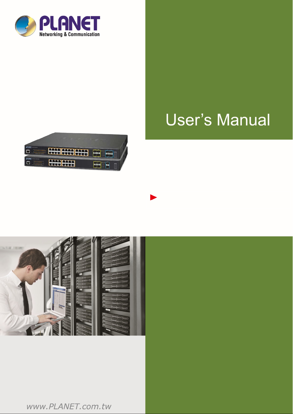
Redundant Ring, Fast Recovery for Critical Network Applications
The GS-5220 PoE series supports redundant ring technology and features strong, rapid self-recovery capability to prevent
interruptions and external intrusions. It incorporates advanced ITU-T G.8032 ERPS (Ethernet Ring Protection Switching)
technology, IEEE 802.1s Multiple Spanning Tree Protocol (MSTP), and dual power input system into customer’s industrial
automation network to enhance system reliability and uptime in harsh factory environments. In a certain simple ring network,
the recovery time of data link can be as fast as 10ms.
Page 13
User’s Manual of GS-5220 PoE Series Managed Switch
13
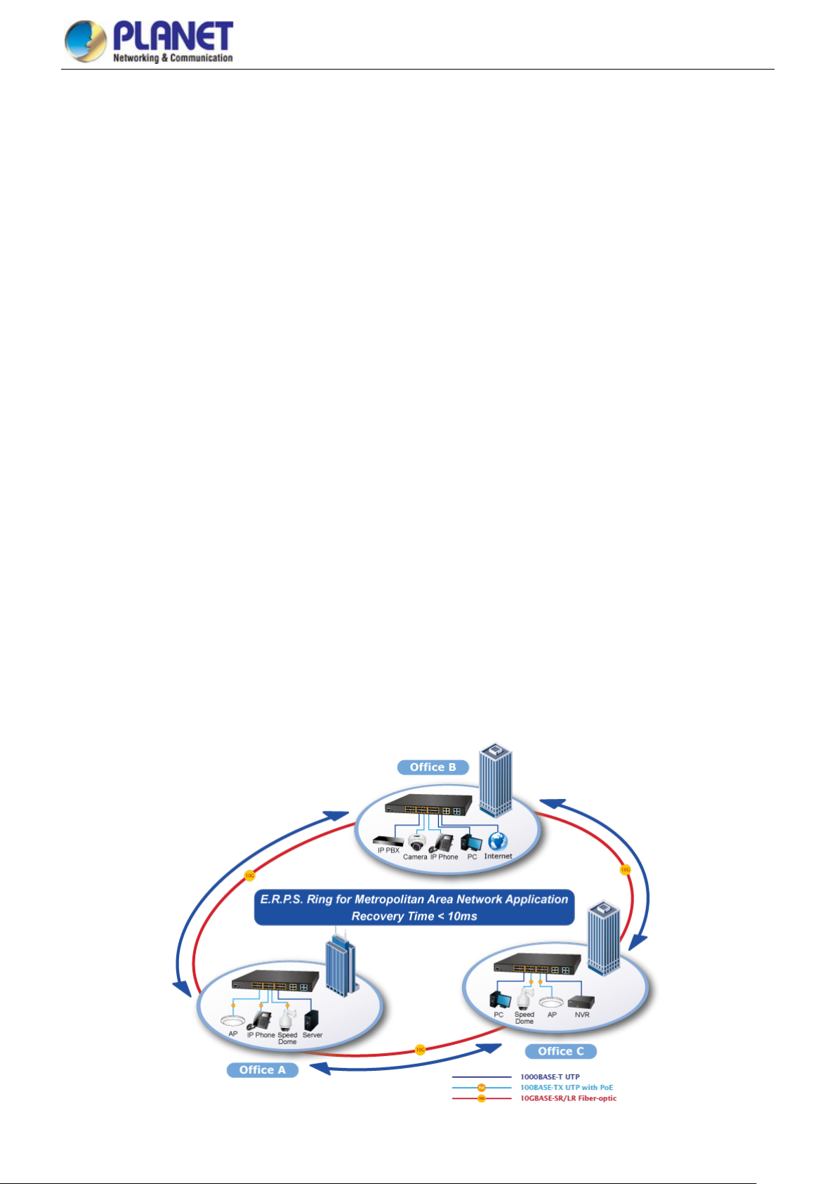
Convenient and Smart ONVIF Devices with Detection Feature
PLANET has newly developed an awesome feature -- ONVIF Support -- which is specif ica ll y designed for co-operating with
Video IP Surveillances. From the GS-5220 PoE Series GUI, clients just need one click to search and show all of the ONVIF
devices via network application. In addition, clients can upload floor images to the switch series, making the deployments of
surveillance and other devices easy for planning and inspection purposes. Moreover , clients can get real-time surveillance’s
information and online/offline status. T hey allow PoE reboot control from the GUI.
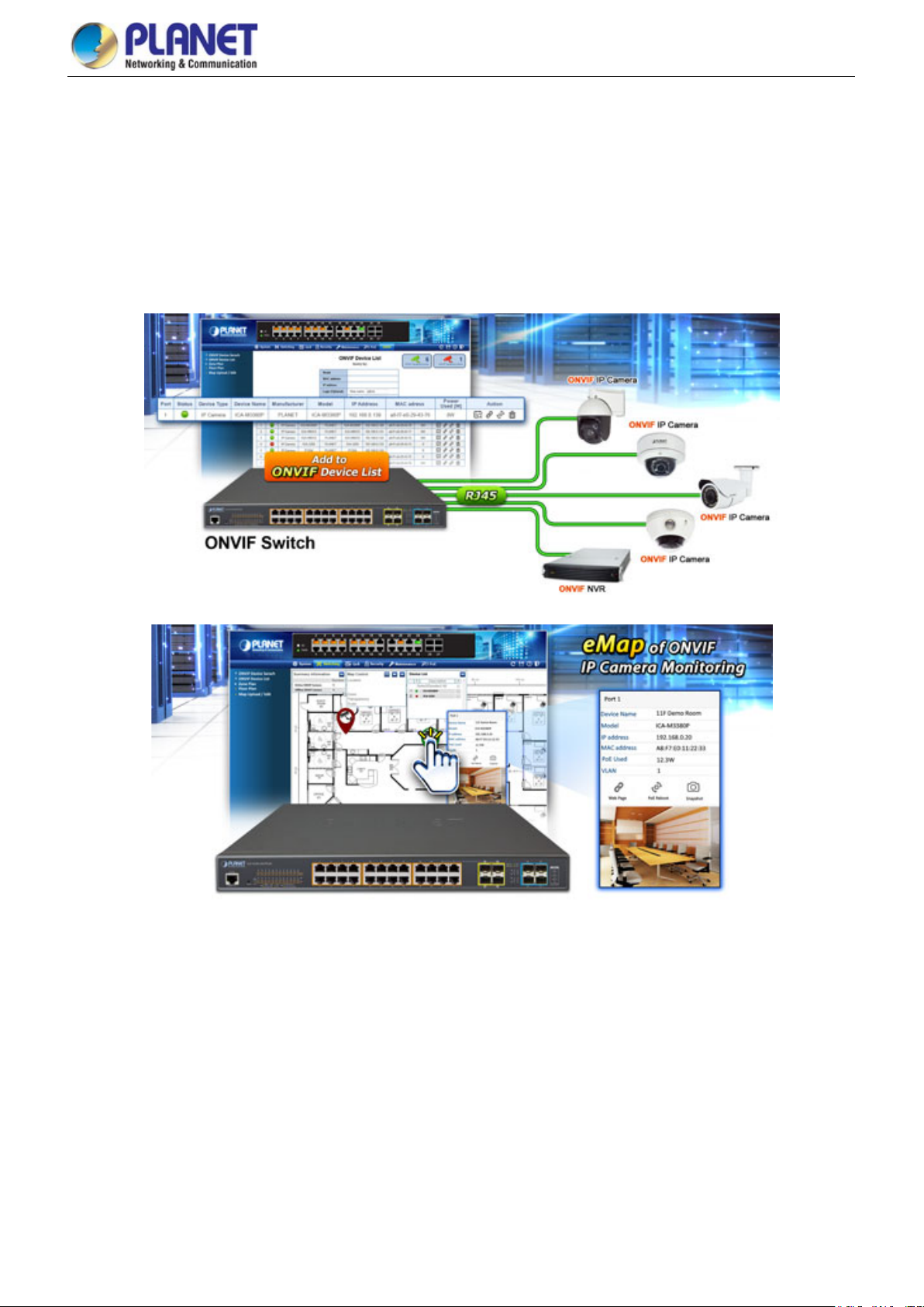
75 Watts of Power over 4-pair UTP
The GS-5220-24UP(L)4X(R) PoE Series ultra PoE solution adopts the IEEE 802.3at/af standard. Instead of delivering power
over 2-pair twisted UTP – be it end-span (Pins 1,2,3 and 6) or mid-span (Pins 4,5,7 and 8), they provide the capability to s our c e
up to 75 watts of power by using all the four pairs of standard Cat.5e/6 Ethernet cabling. In the new 4-pair system, two PSE
controllers will be used to power both the data pairs and the spare pairs. They can offer more PoE applications, such as:
■ PoE PTZ speed dome
■ Any network device that needs higher PoE power to work normally
■ Thin-client
■ AIO (All-in-One) touch PC
■ Remote digital signage display
Page 14
User’s Manual of GS-5220 PoE Series Managed Switch
14
Built-in Unique PoE Functions for Powered Devices Management
Being the managed PoE switches for surveillance, wireless and VoIP networks, the GS-5220 PoE Series features the following
special PoE management functions:
PD alive check
Scheduled power recycling
PoE schedule
PoE usage monitoring
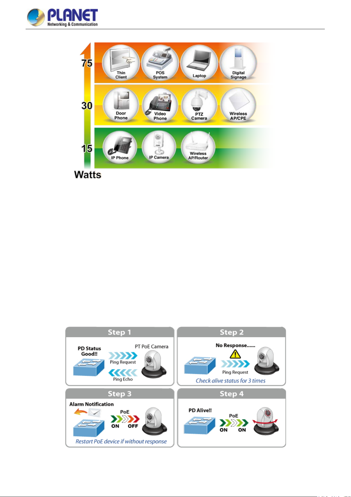
Intelligent Powered Device Alive Check
The GS-5220 PoE Series can be configured to monitor connected PD (powered device) status in real t ime v ia ping ac tion. Once
the PD stops working and resp ondin g, the GS-5220 PoE Series will resume the PoE port p o wer and bring the PD back to work.
They will greatly enhance the network reliability through the PoE port resetting the PD’s power source and reducing
administrator management burden.
Page 15
User’s Manual of GS-5220 PoE Series Managed Switch
15
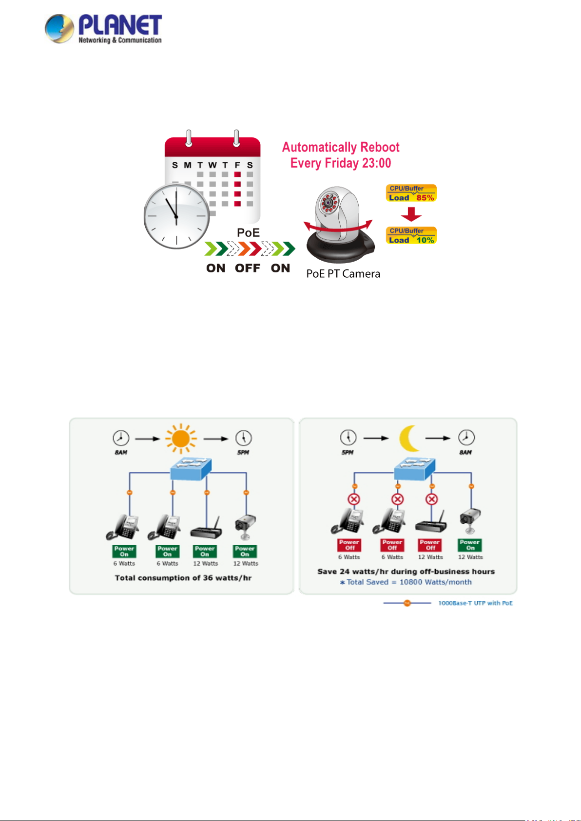
Scheduled Power Recycling
The GS-5220 PoE Series allows each of the connected PoE IP cameras or PoE wireless access poi nts to re boot at a specified
time each week. Therefore, they will reduce the chance of IP camera or AP crash resulting from buffer overflow.
PoE Schedule for Energy Saving
Under the trend of energy saving worldwide and contributing to environmental protection, the GS-5220 PoE Series can
effectively control the power supply besides their capability of giving high watts power. The “PoE schedule” function helps you
to enable or disable PoE power feeding for each PoE port during specified time intervals and it is a powerful function to help
SMBs or enterprises save power and money . It also increases security by powering off PDs that should not be in use during
non-business hours.
PoE Usage Monitoring
Via the power usage chart in the web management interface, the GS-5220 PoE Series enables the administrator to monitor the
status of the power usage of the connected PDs in real time. Thus, they greatly enhance the management efficiency of the
facilities.
Layer 3 Routing Support
The GS-5220 PoE Series enables the administrator to conveniently boost network efficiency by configuring Layer 3 IPv4/IPv6
VLAN static routing manually, and the OSPFv2 (Open Shortest Path First) settings automatically. The OSPF is an interior
Page 16
User’s Manual of GS-5220 PoE Series Managed Switch
16
dynamic routing protocol for autonomous system based on link state. The protocol creates a database for link state by
exchanging link states among Layer 3 switches, and the n us es the Shor test Path First al gor ithm to g enerat e a rout e tab le base d
on that database.
Cost-effective 10Gbps Uplink Capacity
10G Ethernet is a big leap in the evolution of Ethernet. The four 10G SFP+ slots of the GS-5220 PoE Series support
dual-speed 10GBASE-SR/LR or 1000BASE-SX/LX, meaning the administrator now can flexibly choose the suitable
SFP/SFP+ transceiver according to the transmission distance or the transmission speed required to extend the network
efficiently. They greatly support SMB network to achieve the maximum performance of 10Gbps in a cost-effective way.
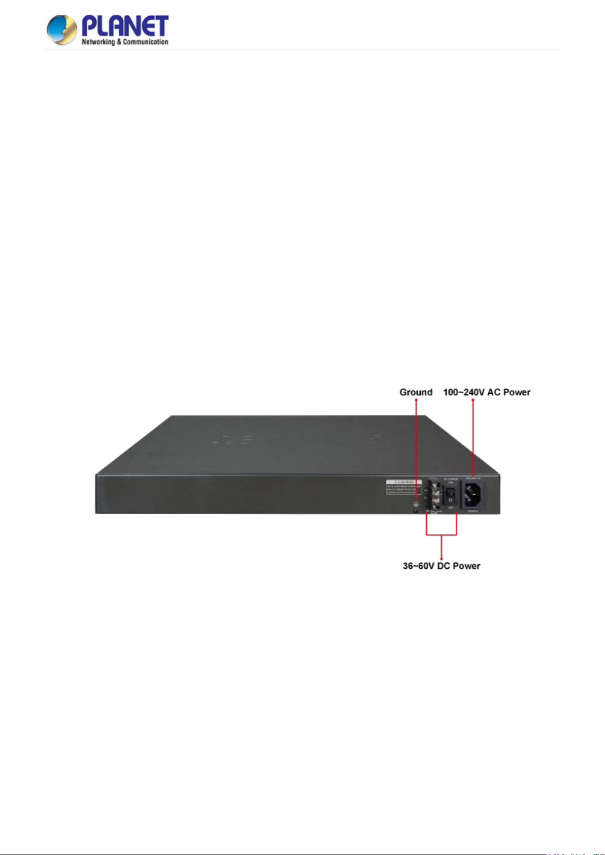
Redundant AC/DC Power Supply to Ensure Continuous Operation
The GS-5220-24P(L)4XR, GS-5220-48PL4XR, GS-522016UP4S2XR and GS-5220-24UP(L)4XR are particular ly equ ippe d with
one 100~240V AC power supply unit and one 36~60V DC power supply unit to provide an enhanced reliable and scalable
redundant power supply. The continuous power system is specifically designed to fulfill the demands of high-tech facilitie s
requiring the highest power integrity. With the 36~60V DC power supply, the GS-5220-24P(L)4XR, GS-5220-48PL4XR,
GS-522016UP4S2XR and GS-5220-24UP(L)4XR are able to act as a telecom-level device that can be located in the electronic
room.
Environment-friendly, Smart Fan Design for Silent Operation
The GS-5220 PoE Series features a 19-inch metal housing, a low noise design and an effective ventilat ion sy ste m. They
support the smart fan technology that automatically controls the speed of the built-in fan to reduce noise and maintain the
temperature of the PoE switch for optimal power output capability. The GS-5220 PoE Series is able to operate reliably, stably
and quietly in any environment without affecting its performance.
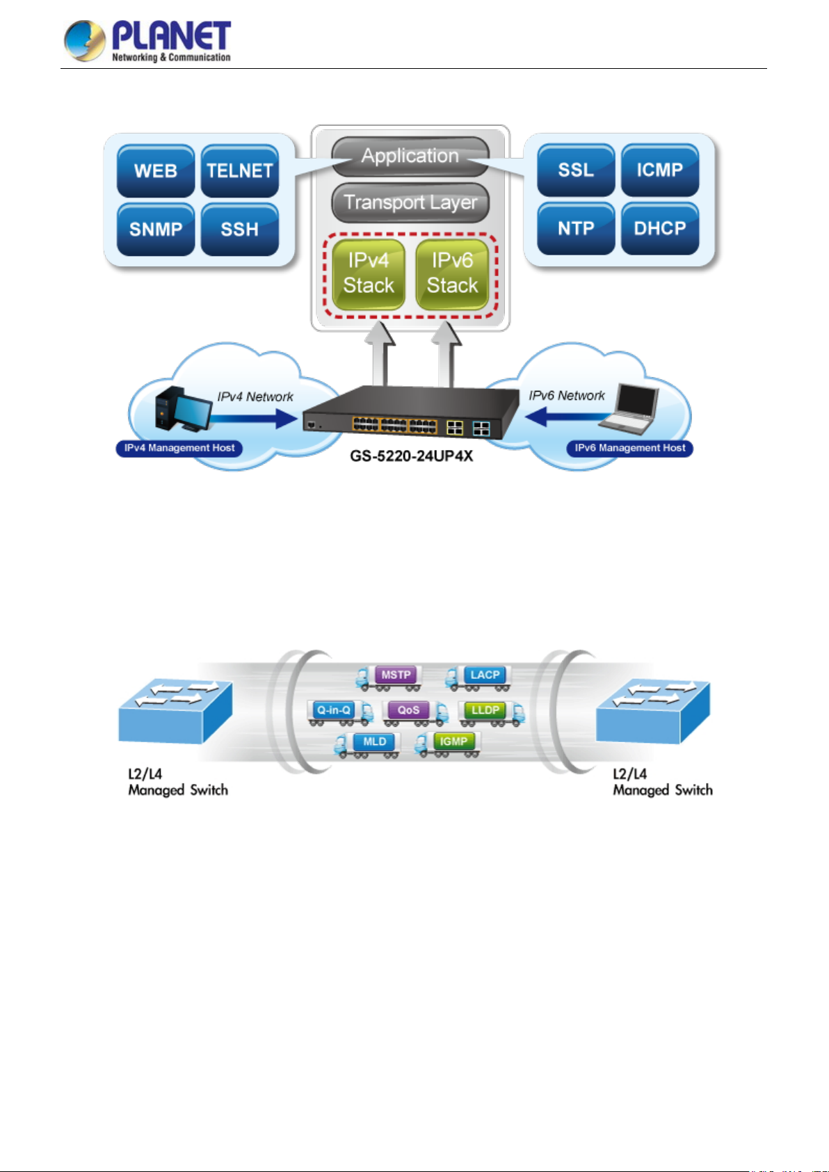
Solution for IPv6 Networking
By supporting IPv6/IPv4 dual stack and plenty of management functions with easy and friendly user interfaces, the GS-5220
PoE Series is the best choice for IP surveillance, VoIP and wireles s servic e prov id ers to deploy the IPv6 network. They also
help the SMBs to step in the IPv6 era with the lowest investment and without having to replace the network facilities while the
ISPs construct the IPv6 FTTx edge network.
Page 17
User’s Manual of GS-5220 PoE Series Managed Switch
17
Robust Layer 2 Features
The GS-5220 PoE Series can be programmed for advanced switch management functions, such as dynamic port link
aggregation, Q-in-Q VLAN, Multiple Spanning Tree Protocol (MSTP), Layer 2/4 QoS, bandwidth control and IGMP/MLD
snooping. The GS-5220 PoE Series allows the operation of a high-speed trunk combining with multiple ports.
Powerful Security
The GS-5220 PoE Series offers a comprehensive Layer 2 to Layer 4 access control list (ACL) for enforcing security to the
edge. It can be used to restrict to network access by denying packets based on source and destination IP address, TCP/UDP
port number or defined typical network applications. Its protection mechanism also comprises 802.1x Port-based and
MAC-based user and device authentication. With the private VLAN function, com mun ic ati on betw een edge port s can be
prevented to ensure user privacy.
Enhanced Security and Traffic Control
The GS-5220 PoE Series also provides DHCP Snooping, IP Source Guard and Dynamic AR P Inspection functions to
prevent IP snooping from attack and discard ARP packets with invalid MAC address. The network administrator can now
construct highly-secure corporate networks with considerably less time and effort than before.
Page 18
User’s Manual of GS-5220 PoE Series Managed Switch
18
User-friendly Secure Management
For efficient management, the GS-5220 PoE Series is equipped w ith con sole, w eb and SNM P man agemen t inter faces . With the
built-in web-based management interface, it offers an easy-to-use, platform independent management and configuration facility.
The GS-5220 PoE Series supports SNMP and it can be managed via any management software based on the standard SNMP
v1 or v2 Protocol. For reducing product learning time, the GS-5220 PoE Series offers Cisco-like command via T elnet or
console port and cust omer doesn’t need to learn new command from these switches. Moreover , the GS-5220 PoE Series offers
the remotely secure management by supporting SSH, SSL and SNMP v3 connection where the packet content can be
encrypted at each session.
Flexible and Extendable Solution
The 4 mini-GBIC SFP slots built in the GS-5220 PoE Series support dual speed as it features 100BASE-FX and
1000BASE-SX/LX SFP (Small Form-factor Pluggable) fiber-optic modules. Now the administrator can flexibly choose the
suitable SFP transceiver according to not only the transmission distance, but also the transmission speed required. The
distance can be extended from 550 m to 2 km (multi-mode fiber) and to 10/20/30/ 4 0/50/ 70/120 km (single-mode fiber or WDM
fiber). They are well suited for applications within the enterprise data centers and distributions.
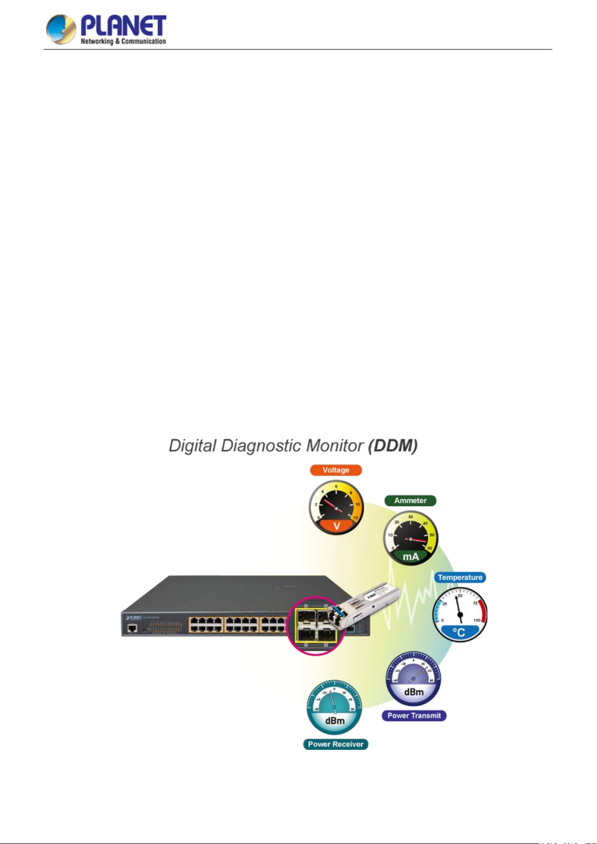
Intelligent SFP/SFP+ Diagnosis Mechanism
The GS-5220 PoE Series supports SFP-DDM (Digital Diagnostic Monitor) function that greatly h elp s n etwork administrator t o
easily monitor real-time parameters of the SFP and SFP+ transceivers, such as optical output power, optical input power,
temperature, laser bias current, and transceiver supply voltage.
Page 19

User’s Manual of GS-5220 PoE Series Managed Switch
19
1.3 How to Use This Manual
This User’s Manual is structured as follows:
Section 2, INSTALLATION
The section explains the functi ons of the Managed Switch and how to physically install the Managed Switch.
Section 3, SWITCH MANAGEMENT
The section contains the i nformation about the software function of the Managed Switch.
Section 4, WEB CONFIGURATION
The section explains how to manage the Managed Sw itch by Web interface.
Section 5, SWITCH OPERATION
The chapter explains how to do the switch operation of the Managed Switch.
Section 6, TROUBLESHOOTING
The chapter explains how to do troubleshooting of the Managed Switch.
Appendix A
The section contains cable inf ormation of the Managed Switch.
Page 20

User’s Manual of GS-5220 PoE Series Managed Switch
20
1.4 Product Features
Physical Port (GS-5220-24P(L)4X(R)/GS-5220-48P(L)4X(R))
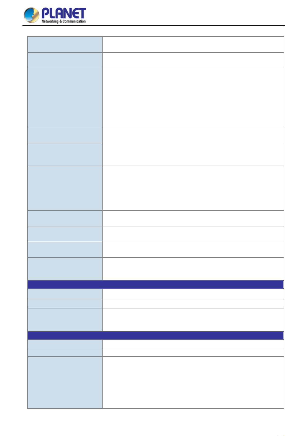
■ 24/48 10/100/1000BASE-T Gigabit RJ45 copper ports with 24-/48-port IEEE 802.3af/at PoE+ injector
■ 4 10GBASE-SR/LR SFP+ slots, compatible with 1000/2500BASE-SX/LX/BX SFP
■ RJ45 console interface for switch basic management and setup
Physical Port (GS-5220-8UP2T2X)
8-port 10/100/1000BASE-T with 72W PoE injector
2-port 1/10G BASE-X SFP+
RS-232 RJ45 console interface for switch basic management and setup
Physical Port (GS-5220-8P2T2X)
8-port 10/100/1000BASE-T with 36W PoE injector
2-port 1/10G BASE-X SFP+
RS-232 RJ45 console interface for switch basic management and setup
Physical Port (GS-5220-16UP4S2X(R))
■ 16 10/100/1000BASE-T Gigabit RJ45 copper ports with 16-port IEEE 802.3af/at/bt Ultra PoE injector
■ 4 100/1000BASE-X mini-GBIC/SFP slots
■ 2 10GBASE-SR/LR SFP+ slots, compatible with 1000BASE-SX/LX/BX SFP
■ RJ45 console interface for switch basic management and set up
Physical Port (GS-5220-24UP(L)4X(R))
■ 24 10/100/1000BASE-T Gigabit RJ45 copper ports with 24-port IEEE 802.3af/at PoE+ injector
■ 4 10GBASE-SR/LR SFP+ slots, compatible with 1000BASE-SX/LX/BX SFP
■ RJ45 console interface for switch basic management and set up
Ultra Power over Ethernet (GS-5220-8UP2T2X/GS-5220-16UP4S2X(R)/GS-5220-24UP(L)4X(R))
■ Complies with IEEE 802.3at Power over Ethernet Plus, end-span/mid-span PSE
■ Backward compatible with IEEE 802.3af Power over Ethernet
■ Up to 8/16/24 ports of IEEE 802.3af/IEEE 802.3at/IEEE 802.3bt ultra PoE devices powered
■ Supports PoE power up to 75 watts for each ultra PoE port
■ Auto detects powered device (PD)
■ Circuit protection prevents power interference between ports
■ Remote power feeding up to 100 meters
■ PoE management
− Total PoE power budget control
− Per port PoE function enable/disable
− PoE admin-mode control
− PoE port power feeding priority
− Per PoE port power limitation
− PD classific ation detection
− Temperature threshold control
− PD alive check
− PoE schedule
Page 21

User’s Manual of GS-5220 PoE Series Managed Switch
21
Power over Ethernet Plus (GS-5220-8P2T2X /GS-5220-24P(L)4X(R)/GS-5220-48P(L)4X(R))
■ Complies with IEEE 802.3at Power over Ethernet Plus/end-span PSE
■ Backward compatible with IEEE 802.3af Power over Ethernet
■ Up to 24/48 ports of IEEE 802.3af/IEEE 802.3at devices powered
■ Supports PoE power up to 36 watts for each PoE port
■ Auto detects powered device (PD)
■ Circuit protection prevents power interference between ports
■ Remote power feeding up to 100 meters
■ PoE management
− Total PoE power budget control
− Per port PoE function enable/disable
− PoE admin-mode control
− PoE port power feeding priority
− Per PoE port power limitation
− PD classific ation detection
− Temperature threshold control
− PD alive check
− PoE schedule
Layer 2 Features
■ Prevents packet loss with back pressure (half-duplex) and IEEE 802.3x pause frame flow control (full-duplex)
■ High performance of Store-and-Forward architecture and runt/CRC filtering eliminates erroneous packets to optimize
the network bandwidth
■ Storm Control support
− Broadcast/Multicast/Unknown unicast
■ Supports VLAN
− IEEE 802.1Q tagged VLAN
− Up to 4K VLANs groups, out of 4094 VLAN IDs
− Supports provider bridging (VLAN Q-in-Q, IEEE 802.1ad)
− Private VLAN Edge (PVE)
− Protocol-based VLAN
− MAC-based VLAN
− Voice VLAN
■ Supports Spanning Tree Protocol
− IEEE 802.1D Spanning Tree Protocol
− IEEE 802.1w Rapid Spanning Tree Protocol
− IEEE 802.1s Multiple Spanning Tree Protocol, spanning tree by VLAN
− BPDU Guard
■ Supports Link Aggregation
− 802.3ad Link Aggregation Control Protocol (LACP)
− Ci sco ether-channel (static trunk)
− Maximum 14 trunk groups, up to 8 ports per trunk group (GS-5220-24P(L)4X(R))
− Maximum 26 trunk groups, up to 4 ports per trunk group (GS-5220-48P(L)4X(R))
− Maximum 6 trunk groups, up to 4 ports per trunk group (GS-5220-8P2T2X /GS-5220-8UP2T2X)
− Maximum 11 trunk groups, up to 6 ports per trunk group (GS-5220-16UP4S2X(R))
− Maximum 14 trunk groups, up to 8 ports per trunk group (GS-5220-24UP(L)4X(R))
■ Provides port mirror (many-to-1)
■ Port mirroring to monitor the incoming or outgoing traffic on a particular port
■ Loop protection to avoid broadcast loops
Layer 3 Features
Page 22

User’s Manual of GS-5220 PoE Series Managed Switch
22
■ Supports maximum 128 static routes and route summarization
■ IP dynamic routing protocol supports OSPFv2
■ Routing interface provides per VLAN routing mode
Quality of Service
■ Ingress Shaper and Egress Rate Limit per port bandwidth control
■ 8 priority queues on all switch ports
■ Traffic classification
- IEEE 802.1p CoS
- TOS/DSCP/IP precedence of IPv4/IPv6 packets
- IP TCP/UDP port number
- Ty pical networ k applic at io n
■ Strict priority and Weighted Round Robin (WRR) CoS policies
■ Supports QoS and In/Out bandwidth control on each port
■ Traffic-policing on the switch port
■ DSCP remarking
Multicast
Supports IGMP snooping v1, v2 and v3
Supports MLD snooping v1 and v2
Q uerier mode support
IGMP snooping port filtering
MLD snooping port filtering
Mu lticast VLAN Registration (MVR) support
Security
Authentication
- IEEE 802.1x port-based/MAC-based network access authentication
- Built-in RADIUS client to cooperate with the RADIUS servers
- TACACS+ login users access authentication
- RADIUS/TACACS+ users access authentication
Access Control List
- IP-based Access Control List (ACL)
- MAC-based Access Control List
Source MAC/IP address binding
DHCP Snooping to filter untrusted DHCP messages
Dy namic A RP Inspection discards ARP packets with invalid MAC address to IP address binding
IP Source Guard prevents IP spoofing attacks
IP address access management to prevent unauthorized intruder
Management
IPv4 and IPv6 dual stack management
Switch Management Interfaces
- Console/Telnet Command Line Interface
- Web switch management
- SNMP v1, v2c, and v3 switch management
- SSH/SSL secure access
IPv6 IP address/NTP/DNS management
Built-in Trivial File Transfer Protocol (TFTP) client
BOOTP and DHCP for IP address assignment
Page 23

User’s Manual of GS-5220 PoE Series Managed Switch
23
System Maintenance
- Firmware upload/download via HTTP/TFTP
- Reset button for system reboot or reset to factory default
- Dual images
DHCP Relay
DHCP Option 82
User Privilege levels control
NTP (Network Time Protocol)
Link Layer Discovery Protocol (LLDP) and LLDP-MED
Network Diagnostic
- ICMPv6/ICMPv4 remote ping
- Cable diagnostic technology provides the mechanism to detect and report potential cabling issues
SMTP/Syslog remote alarm
Four RMON groups (history, statistics, alarms and events)
SNMP trap for interface Link Up and Link Down notification
System Log
PLANET Smart Discovery Utility for deployment management
Smart fan with speed control
Redundant Power System (GS-5220-24P(L)4XR/GS-5220-48PL4XR/GS-5220-16UP4S2XR/GS-5220-24UP(L)4XR)
■ Redundant 100~240V AC/36-60V DC dual power
■ Active-active redundant power failure protection
■ Backup of catastrophic power failure on one supply
Fault tolerance and resilience
Page 24

User’s Manual of GS-5220 PoE Series Managed Switch
24
Hardware Specifications
Hardware Version
Compatible with 100BASE-FX S FP tran sc eiv er
Compatible with 1000BASE-SX/LX/BX SFP transceiver
Switch Fabric
Throughput
Back pressure for half duplex
Jumbo Frame
Weight
ESD Protection
Fan
PoE Standard
PoE Power Supply Type
PoE Power Budget
PoE Ability PD @ 7 watts
Layer 2 Management Functions
1.5 Product Specifications
GS-5220-24P(L)4X(R) series
Product
Copper Ports
SFP/mini-GBIC Slots
SFP+ Slots
Console
Switch Architecture
Address Table
Shared Data Buffer
Flow Control
Reset Button
Dimensions (W x D x H)
Power Consumption
GS-5220-24P4X GS-5220-24P4XR GS-5220-24PL4X GS-5220-24PL4XR
2
24 10/100/1000BASE-T RJ45 auto-MDI/MDI-X ports
4 100/1000BASE-X SFP interfaces, shared with Port-21 to Port-24
4 10GBASE-SR/LR SFP+ interfaces (Port-25 to Port-28)
1 x RS232-to-RJ45 serial port (115200, 8, N, 1)
Store-and-Forward
128Gbps/non-blocking
95.23Mpps@64Bytes
16K entries, automatic sourc e address learning and aging
32M bits
IEEE 802.3x pause frame for full duplex
10K bytes
< 5 sec: System reboot
> 5 sec: Factory default
440 x 300 x 44.5 mm, 1U height
4546g 4570g 5040g 5071g
Max.
452watts/1550.8BTU
AC: Max. 446.6
watts/1522.9 BTU
DC: Max. 33.9
watts/115.5 BTU
Max.
661.5watts/2269.2
BTU
AC: Max.661.5
watts/2269.2 BTU
DC: Max.
34.5watts/118.4BTU
Power Requirements – AC
Power Requirements – DC
Power over Ethernet
PoE Power Output
Power Pin Assignment
PoE Ability PD @ 15.4 watts
PoE Ability PD @ 30.8 watts
Port Configuration
AC 100~240V, 50/60Hz, 8A AC 100~240V, 50/60Hz, 10A
-- D C 36~60V, 2A -- D C 36~60V, 2A
6KV DC
3 smart fans
IEEE 802.3at PoE+ PSE
End-span
36 watts (max.)
End-span : 1/2(-), 3/6(+)
400 watts (max.) 600 watts (max.)
24 units 24 units
24 units 24 units
12 units 20 units
Port disable/enable
Auto-negotiation 10/100/1000Mbps full and half duplex m ode s election
Flow control disable/enable
Page 25
25
Layer 3 Functions
Ipv6 hardware static routing
Basic Management Interfaces
Port Status
Port Mirroring
VLAN
Link Aggregation
Spanning Tree Prot ocol
QoS
IGMP Snooping
MLD Snooping
Access Control List
Bandwidth Control
User’s Manual of GS-5220 PoE Series Managed Switch
Display each port’s speed duplex mode, link status, flow control status,
auto-negotiation status, trunk status
TX/RX/Both
Many-to-1 monitor
802.1Q tagged based VLAN
Q-in-Q tunneling
Private VLAN Edge (PVE)
MAC-based VLAN
Protocol-based VLAN
Voice VLAN
MVR (Multicast VLAN registration)
Up to 4K VLAN groups, out of 4095 VLAN IDs
IEEE 802.3ad LACP/static trunk
14 groups with 8 port per trunk
IEEE 802.1D Spanning Tree Protocol (STP)
IEEE 802.1w Rapid Spanning Tree Protocol (RSTP)
IEEE 802.1s Multiple Spa nni n g Tree Protocol (MSTP)
Traffic classification b ased, strict priority and WRR
8-level priority for switching:
- Port number
- 802.1p priority
- 802.1Q VLAN tag
- DSCP/ToS field in IP packet
IGMP (v1/v2/v3) snooping, up to 255 multicast groups
IGMP querier mode support
MLD (v1/v2) snooping, up to 255 multicast groups
MLD querier mode support
IP-based ACL/MAC-based ACL
Up to 256 entries
Per port bandwidth control
Ingress: 100Kbps~1000Mbps
Egress: 100Kbps~1000Mbps
IP Interfaces Max. 128 VLAN interfaces
Routing Ta ble Max. 128 routing entries
Routing Protocols
Management
Secure Management Interfac es SSHv2, TLSv1.2, SNMP v3
SNMP MIBs
Ipv4 OSPFv2
Ipv4 hardware static routing
Console; Telnet; Web browser; SNMP v1, v2c
RFC 1213 MIB-II
RFC 1493 Bridge MIB
RFC 1643 Ethernet MIB
RFC 2863 Interface MIB
RFC 2665 Ether-Like MIB
RFC 2819 RMON MIB (Groups 1, 2, 3 and 9)
RFC 2737 Entity MIB
Page 26

26
Standards Conformance
Regulatory Compliance
Standards Compliance
Environment
Operating
Storage
User’s Manual of GS-5220 PoE Series Managed Switch
RFC 2618 RADIUS Client MIB
RFC 2863 IF-MIB
RFC 2933 IGMP-STD-MIB
RFC 3411 SNMP-Frameworks-MIB
RFC 4292 IP Forward MIB
RFC 4293 IP MIB
RFC 4836 MAU-MIB
IEEE 802.1X PAE
LLDP
FCC Part 15 Class A, CE
IEEE 802.3 10BASE-T
IEEE 802.3u 100BASE-TX/100BASE-FX
IEEE 802.3z Gigabit SX/LX
IEEE 802.3ab Gigabit 1000T
IEEE 802.3ae 10Gb/s Ethernet
IEEE 802.3x flow control and back pressure
IEEE 802.3ad port trunk with LACP
IEEE 802.1D Spanning Tree Protocol
IEEE 802.1w Rapid Spanning Tree Protocol
IEEE 802.1s Multiple Spanning Tree Protocol
IEEE 802.1p Class of Service
IEEE 802.1Q VLAN tagging
IEEE 802.1x Port Authentication Network Control
IEEE 802.1ab LLDP
IEEE 802.3af Power over Ethernet
IEEE 802.3at Power over Ethernet Plus
RFC 768 UDP
RFC 793 TFTP
RFC 791 IP
RFC 792 ICMP
RFC 2068 HTTP
RFC 1112 IGMP v1
RFC 2236 IGMP v2
RFC 3376 IGMP v3
RFC 2710 MLD v1
FRC 3810 MLD v2
RFC 2328 OSPF v2
Temperature: 0 ~ 50 degrees C
Relative Humidity: 5 ~ 95% (non-condensing)
Temperature: -10 ~ 70 degrees C
Relative Humidity: 5 ~ 95% (non-condensing)
Page 27

User’s Manual of GS-5220 PoE Series Managed Switch
27
Hardware Specifications
Hardware Version
Compatible with 1000/2500BASE-SX/LX/BX SFP trans ceiver
Console
Switch Architecture
Throughput
Address Table
Jumbo Frame
> 5 sec: Factory default
Dimensions (W x D x H)
Fan
PoE Power Supply Type
PoE Power Output
PoE Ability PD @ 7 watts
watts
GS-5220-48P(L)4X(R) series
Product
Copper Ports
SFP+ Slots
Switch Fabric
Shared Data Buffer
Flow Control
Reset Button
Weight
Power Consumption
GS-5220-48P4X GS-5220-48PL4XR
4
48 10/100/1000BASE-T RJ45 auto-MDI/MDI-X ports
4 10GBASE-SR/LR SFP+ interfaces (Port-25 to Port-28)
1 x RS232-to-RJ45 serial port (115200, 8, N, 1)
Store-and-Forward
176Gbps/non-blocking
130Mpps@64Bytes
16K entries, automatic source address learning and aging
32M bits
IEEE 802.3x pause frame for full duplex
Back pressure for half duplex
10K bytes
< 5 sec: System reboot
440 x 300 x 44.5 mm, 1U height
4950g 5071g
Max. 461 watts/1582 BTU
AC: Max.900 watts/2333 BTU
DC: Max. 36.6watts/124.88BTU
Power Requirements – AC
Power Requirements – DC
ESD Protection
Power over Ethernet
PoE Standard
Power Pin Assignment
PoE Power Budget
PoE Ability PD @ 15.4
PoE Ability PD @ 30.8
watts
Layer 2 Management Functions
Port Configuration
Port Status
Port Mirroring
-- DC 36~60V, 2A
6KV DC
3 smart fans
IEEE 802.3at PoE+ PSE
End-span
36 watts (max.)
End-span : 1/2(-), 3/6(+)
400 watts (max.) 720 watts (max.)
48 units 48 units
26 units 48 units
13 units 24 units
Port disable/enable
Auto-negotiation 10/100/1000Mbps full and half duplex m ode s election
Flow control disable/enable
Display each port’s speed duplex mode, link stat us, flow control status,
auto-negotiation status, trunk status
TX/RX/Both
Many-to-1 monitor
AC 100~240V, 50/60Hz, 7A AC 100~240V, 50/60Hz, 9A
Page 28

28
Interfaces
VLAN
Link Aggregation
Spanning Tree Prot ocol
QoS
IGMP Snooping
MLD Snooping
Access Control List
Bandwidth Control
Layer 3 Functions
User’s Manual of GS-5220 PoE Series Managed Switch
802.1Q tagged based VLAN
Q-in-Q tunneling
Private VLAN Edge (PVE)
MAC-based VLAN
Protocol-based VLAN
Voice VLAN
MVR (Multicast VLAN registration)
Up to 4K VLAN groups, out of 4095 VLAN IDs
IEEE 802.3ad LACP/static trunk
26 groups with 4 port per trunk
IEEE 802.1D Spanning Tree Protocol (STP)
IEEE 802.1w Rapid Spanning Tree Protocol (RSTP)
IEEE 802.1s Multiple Spanning Tree Protocol (MSTP)
Traffic classification b ased, strict priority and WRR
8-level priority for switching:
- Port number
- 802.1p priority
- 802.1Q VLAN tag
- DSCP/ToS field in IP packet
IGMP (v1/v2/v3) snooping, up to 255 multicast groups
IGMP querier mode support
MLD (v1/v2) snooping, up to 255 multicast groups
MLD querier mode support
IP-based ACL/MAC-based ACL
Up to 256 entries
Per port bandwidth control
Ingress: 100Kbps~1000Mbps
Egress: 100Kbps~1000Mbps
IP Interfaces Max. 128 VLAN interfaces
Routing Ta ble Max. 128 routing entries
IPv4 OSPFv2
Routing Protocols
Management
Basic Management
Interfaces
Secure Management
SNMP MIBs
IPv4 hardware static routing
IPv6 hardware static routing
Console; Telnet; Web browser; SNMP v1, v2c
SSH, TLS, SSL, SNMP v3
RFC 1213 MIB-II
RFC 1493 Bridge MIB
RFC 1643 Ethernet MIB
RFC 2863 Interface MIB
RFC 2665 Ether-Like MIB
RFC 2819 RMON MIB (Groups 1, 2, 3 and 9)
RFC 2737 Entity MIB
RFC 2618 RADIUS Client MIB
RFC 2863 IF-MIB
Page 29

29
Standards Conformance
Regulatory Compliance
Standards Compliance
Environment
Operating
Storage
User’s Manual of GS-5220 PoE Series Managed Switch
RFC 2933 IGMP-STD-MIB
RFC 3411 SNMP-Frameworks-MIB
RFC 4292 IP Forward MIB
RFC 4293 IP MIB
RFC 4836 MAU-MIB
IEEE 802.1X PAE
LLDP
FCC Part 15 Class A, CE
IEEE 802.3 10BASE-T
IEEE 802.3u 100BASE-TX/100BASE-FX
IEEE 802.3z Gigabit SX/LX
IEEE 802.3ab Gigabit 1000T
IEEE 802.3ae 10Gb/s Ethernet
IEEE 802.3x flow control and back pressure
IEEE 802.3ad port trunk with LACP
IEEE 802.1D Spanning Tree Protocol
IEEE 802.1w Rapid Spanning Tree Protocol
IEEE 802.1s Multiple Spanning Tree Protocol
IEEE 802.1p Class of Service
IEEE 802.1Q VLAN tagging
IEEE 802.1x Port Authentication Network Control
IEEE 802.1ab LLDP
IEEE 802.3af Power over Ethernet
IEEE 802.3at Power over Ethernet Plus
RFC 768 UDP
RFC 793 TFTP
RFC 791 IP
RFC 792 ICMP
RFC 2068 HTTP
RFC 1112 IGMP v1
RFC 2236 IGMP v2
RFC 3376 IGMP v3
RFC 2710 MLD v1
FRC 3810 MLD v2
RFC 2328 OSPF v2
Temperature: 0 ~ 50 degrees C
Relative Humidity: 5 ~ 95% (non-condensing)
Temperature: -10 ~ 70 degrees C
Relative Humidity: 5 ~ 95% (non-condensing)
Page 30
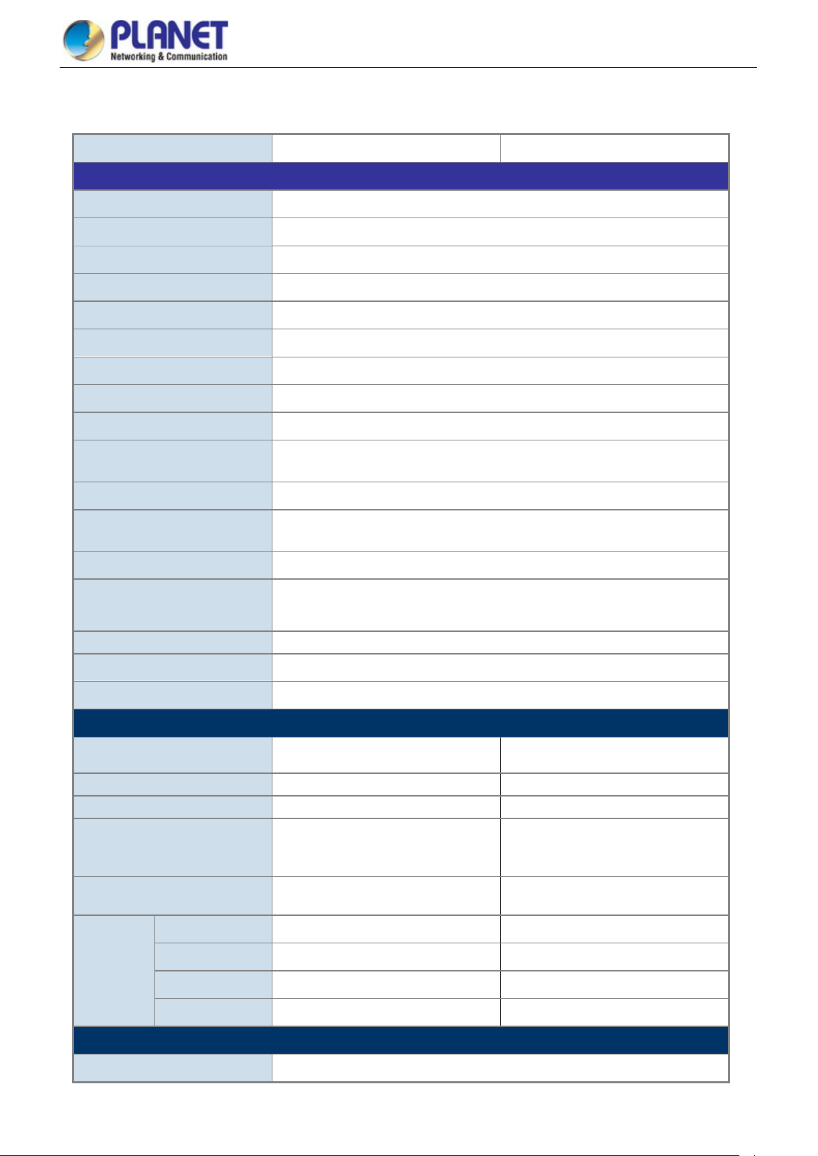
User’s Manual of GS-5220 PoE Series Managed Switch
30
IEEE 802.3af/802.3at/802.3bt Ultra PoE
PoE Power Supply Type
UPoE: 1/2(-), 3/6(+), 4/5(+), 7/8(-)
200 watts (max.) @ 50 degrees C
GS-5220-8P2T2X/GS-5220-8UP2T2X
Product GS-5220-8P2T2X GS-5220-8UP2T2X
Hardware Specifications
Copper Ports 10 x 10/100/1000BASE-T RJ45 auto-MDI/MDI-X interface with Port-1 to Port-10
SFP/mini-GBIC Slots 2 x 1/10G BASE-X SFP interfaces with Port-11 to Port-12
PoE Injector Port 8 ports with 802.3at/af PoE injector function with Port-1 to Port-8
Console 1 x RJ45 serial port (115200 , 8, N, 1)
Switch Architecture Store-and-Forward
Switch Fabric
Throughput
Address Table 16K entries, automatic source address learning and aging
Shared Data Buffer
Flow Control
Jumbo Frame 9KB
Reset Button
Power Requirements
Power Consumption (Full
Loading)
ESD Protection
Dimensions (W x D x H)
Weight
Power over Ethernet
60Gbps/non-blocking
44.642Mpps@ 64Bytes packet
16Mbits
IEEE 802.3x pause frame for full-duplex
Back pressure for half-duplex
< 5 sec: System reboot
> 5 sec: Factory default
100~240V AC, 50/60Hz
258 watts/880BTU (max.)
6KV DC
330 x 200 x 43.5 mm, 1U height
2kg
PoE Standard
PoE Power Output
Power Pin Assignment
PoE Power Budget
PD @ 7 watts
PD @ 15.4 watts
PoE Ability
PD @ 30.8 watts
PD @ 60 watts
Layer 2 Management Functions
Basic Management Interfaces Console , Web browser, SNMP v1, v2c
IEEE 802.3at PoE Plus, PSE
PSE
End-span End-span/Mid-span/UPoE
Per port 54V DC, max. 36 watts Per port 52V DC, max. 72 watts
1/2(-), 3/6(+)
240 watts (max.) @ 25 degrees C
200 watts (max.) @ 50 degrees C
8 units 8 units
8 units 8 units
8 units 8 units
-- 4 units
End-span: 1/2(-), 3/6(+)
Mid-span: 4/5(+), 7/8(-)
240 watts (max.) @ 25 degrees C
Page 31

User’s Manual of GS-5220 PoE Series Managed Switch
31
Secure Management Interfac es SSHv2, TLSv1.2, SNMP v3
ONVIF device discovery
ONVIF
Port Configuration
Port Status
Port Mirroring
VLAN
Link Aggregation
ONVIF device monitoring
Floor Map
Port disable/enable
Auto-negotiation 10/100/1000Mbps full and half duplex m ode s election
Flow Control disable/enable
Display each port’s speed duplex mode, link status, flow control status, auto
negotiation status, trunk status
TX/RX/Both
Many-to-1 monitor
802.1Q tag-based VLAN
Q-in-Q tunneling
Private VLAN Edge (PVE)
MAC-based VLAN
Protocol-based VLAN
Voice VLAN
MVR (Multicast VLAN Registration)
GVRP
Up to 4K VLAN groups, out of 4094 VLAN IDs
IEEE 802.3ad LACP (static trunk)
Supports 6 trunk groups with 4 ports per trunk
QoS
IGMP Snooping
MLD Snooping
Access Control List
Bandwidth Control
SNMP MIBs
Traffic classification b ased, strict priority and WRR
8-level priority for switching
- Port number
- 802.1p priority
- 802.1Q VLAN tag
- DSCP/TOS field in IP packet
IGMP (v1/v2/v3) Snooping, up to 255 multicast groups
IGMP Querier mode support
MLD (v1/v2) Snooping, up to 255 multicast groups
MLD Querier mode support
IP-based ACL/MAC-based ACL
Up to 256 entries
Per port bandwidth control
Ingress: 10Kbps~13000Mbps
Egress: 10Kbps~13000Mbps
RFC 1213 MIB-II
RFC 2863 IF-MIB
RFC 1493 Bridge MIB
RFC 1643 Ethernet MIB
RFC 2863 Interface MIB
RFC 2665 Ether-Like MIB
RFC 2737 Entity MIB
RFC 2819 RMON MIB (Groups 1, 2, 3 and 9)
RFC 2618 RADIUS Client MIB
RFC 3411 SNMP-Frameworks-MIB
IEEE 802.1X PAE
LLDP
Page 32

32
Layer 3 Functions
User’s Manual of GS-5220 PoE Series Managed Switch
MAU-MIB
Power over Ethernet MIB
IP Interfaces
Routing Ta ble
Routing Protocols
Standards Conformance
Regulatory Compliance FCC Part 15 Class A, CE
Standards Compliance
Environments
Operating
Storage
Max. 128 VLAN interfaces
Max. 128 routing entries
IPv4 OSPFv2
IPv4 hardware static routing
IPv6 hardware static routing
IEEE 802.3 10BASE-T
IEEE 802.3u 100BASE-TX
IEEE 802.3z 1000BASE-SX/LX
IEEE 802.3ab 1000BASE-T
IEEE 802.3ae 10Gb/s Ethernet
IEEE 802.3x flow control and back pressure
IEEE 802.3ad port trunk with LACP
IEEE 802.1D Spanning Tree Protocol
IEEE 802.1w Rapid Spanning Tree Protocol
IEEE 802.1s Multiple Spanning Tree Protocol
IEEE 802.1p Class of Service
IEEE 802.1Q VLAN tagging
IEEE 802.1x Port Authentication Network Control
IEEE 802.1ab LLDP
IEEE 802.3af Power over Ethernet
IEEE 802.3at Power over Ethernet Plus
IEEE 802.3bt 4-pair Power over Ethernet (GS-5220-8UP2T2X)
RFC 768 UDP
RFC 793 TFTP
RFC 791 IP
RFC 792 ICMP
RFC 2068 HTTP
RFC 1112 IGMP v1
RFC 2236 IGMP v2
RFC 3376 IGMP v3
RFC 2710 MLD v1
RFC 3810 MLD v2
RFC 2328 OSPF v2
Temperature: 0 ~ 50 degrees C
Relative Humidity: 5 ~ 95% (non-condensing)
Temperature: -10 ~ 70 degrees C
Relative Humidity: 5 ~ 95% (non-condensing)
Page 33

User’s Manual of GS-5220 PoE Series Managed Switch
33
Hardware Specifications
Hardware Version
Compatible with 100BASE-FX S FP tran sc eiv er
Compatible with 1000BASE-SX/LX/BX SFP transceiver
Switch Fabric
Throughput
Back pressure for half-duplex
Jumbo Frame
Weight
ESD Protection
Fan
PoE Standard
PoE Power Supply Type
PoE Power Budget
PoE Ability PD @ 15 watts
Layer 2 Management Functions
GS-5220-16UP(L)4X(R) seri es
Product GS-5220-16UP4S2X GS-5220-16UP4S2XR
2
Copper Ports
SFP/mini-GBIC Slots
16 10/100/1000BASE-T RJ45 auto-MDI/MDI-X ports
4 100/1000BASE-X SFP interfaces,
SFP+ Slots
Console
Switch Architecture
Address Table
Shared Data Buffer
Flow Control
Reset Button
Dimensions (W x D x H)
Power Consumption
Power Requirements – AC
Power Requirements – DC
2 10GBASE-SR/LR SFP+ interfaces (Port-17 to Port-18)
1 x RS232-to-RJ45 serial port (115200, 8, N, 1)
Store-and-Forward
80Gbps/non-blocking
59.52Mpps@64Bytes
16K entries, automatic source address learning and aging
32M bits
IEEE 802.3x pause frame for full-duplex
10K bytes
< 5 sec: System reboot
> 5 sec: Factory default
440 x 300 x 44.5 mm, 1U height
4466g 4503g
Max. 439.4 watts/1498.3 BTU
AC 100~240V, 50/60Hz, 7A
-- DC 36~60V, 2A
AC: Max. 439.4 watts/1498.3 BTU
DC: Max. 31.9 watts/108.7 BTU
Power over Ethernet
PoE Power Output
Power Pin Assignment
PoE Ability PD @ 30 watts
PoE Ability PD @ 60 watts
Port Configuration
Port Status
6KV DC
3 smart fans
IEEE 802.3af/802.3at/802.3bt Ultra PoE PSE
End-span/Mid-span/UPoE
Per port 54V DC, 75 watts (max.)
End-span: 1/2(-), 3/6(+)
Mid-span: 4/5(+), 7/8(-)
UPoE: 1/2(-), 3/6(+),4/5(+), 7/8(-)
400 watts (max.)
16 units
13 units
6 units
Port disable/enable
Auto-negotiation 10/100/1000Mbps full and half duplex m ode s election
Flow control disable/enable
Display each port’s speed duplex mode, link status, flow control status,
auto-negotiation status, trunk status
Page 34

34
Layer 3 Functions
Secure Management Interfac es
RFC 2863 IF-MIB
Port Mirroring
VLAN
Link Aggregation
Spanning Tree Prot ocol
QoS
IGMP Snooping
MLD Snooping
Access Control List
Bandwidth Control
User’s Manual of GS-5220 PoE Series Managed Switch
TX/RX/Both
Many-to-1 monitor
802.1Q tagged based VLAN
Q-in-Q tunneling
Private VLAN Edge (PVE)
MAC-based VLAN
Protocol-based VLAN
Voice VLAN
MVR (Multicast VLAN registration)
Up to 4K VLAN groups, out of 4095 VLAN IDs
IEEE 802.3ad LACP/static trunk
11 groups with 6 port per trunk
IEEE 802.1D Spanning Tree Protocol (STP)
IEEE 802.1w Rapid Spannin g Tree Protocol (RSTP)
IEEE 802.1s Multiple Spanning Tree Protocol (MSTP)
Traffic classification b ased, strict priority and WRR
8-level priority for switching:
- Port number
- 802.1p priority
- 802.1Q VLAN tagging
- DSCP/ToS field in IP packet
IGMP (v1/v2/v3) snooping, up to 255 multicast groups
IGMP querier mode support
MLD (v1/v2) snooping, up to 255 multicast groups
MLD querier mode support
IP-based ACL/MAC-based ACL
Up to 256 entries
Per port bandwidth control
Ingress: 100Kbps~1000Mbps
Egress: 100Kbps~1000Mbps
IP Interfaces Max. 128 VLAN interfaces
Routing Ta ble Max. 128 routing entries
Routing Protocols
Management
Basic Management Interfaces Console; Telnet; Web browser; SNMP v1, v2c
SNMP MIBs
IPv4 OSPFv2
IPv4 hardware static routing
IPv6 hardware static routing
SSH, SSL, SNMP v3
RFC 1213 MIB-II
RFC 1493 Bridge MIB
RFC 1643 Ethernet MIB
RFC 2863 Interface MIB
RFC 2665 Ether-Like MIB
RFC 2819 RMON MIB (Groups 1, 2, 3 and 9)
RFC 2737 Entity MIB
RFC 2618 RADIUS Client MIB
Page 35

35
Standards Conformance
Regulatory Compliance
Standards Compliance
Environment
Operating
Storage
User’s Manual of GS-5220 PoE Series Managed Switch
RFC 2933 IGMP-STD-MIB
RFC 3411 SNMP-Frameworks-MIB
RFC 4292 IP Forward MIB
RFC 4293 IP MIB
RFC 4836 MAU-MIB
IEEE 802.1X PAE
LLDP
FCC Part 15 Class A, CE
IEEE 802.3 10BASE-T
IEEE 802.3u 100BASE-TX/100BASE-FX
IEEE 802.3z Gigabit SX/LX
IEEE 802.3ab Gigabit 1000T
IEEE 802.3ae 10Gb/s Ethernet
IEEE 802.3x flow control and back pressure
IEEE 802.3ad port trunk with LACP
IEEE 802.1D Spanning Tree Protocol
IEEE 802.1w Rapid Spanning Tree Protocol
IEEE 802.1s Multiple Spanning Tree Protocol
IEEE 802.1p Class of Service
IEEE 802.1Q VLAN tagging
IEEE 802.1x Port Authentication Network Control
IEEE 802.1ab LLDP
IEEE 802.3af Power over Ethernet
IEEE 802.3at Power over Ethernet Plus
IEEE 802.3bt 4-pair Power over Ethernet
RFC 768 UDP
RFC 793 TFTP
RFC 791 IP
RFC 792 ICMP
RFC 2068 HTTP
RFC 1112 IGMP v1
RFC 2236 IGMP v2
RFC 3376 IGMP v3
RFC 2710 MLD v1
RFC 3810 MLD v2
Temperature: 0 ~ 50 degrees C
Relative Humidity: 5 ~ 95% (non-condensing)
Temperature: -10 ~ 70 degrees C
Relative Humidity: 5 ~ 95% (non-condensing)
Page 36

User’s Manual of GS-5220 PoE Series Managed Switch
36
Hardware Specifications
Hardware Version
Compatible with 100BASE-FX S FP tran sc eiv er
Compatible with 1000BASE-SX/LX/BX SFP transceiver
Switch Fabric
Throughput
Back pressure for half-duplex
Jumbo Frame
Weight
ESD Protection
Fan
PoE Standard
PoE Power Supply Type
PoE Power Budget
PoE Ability PD @ 15 watts
Layer 2 Management Functions
GS-5220-24UP(L)4X(R) ser ies
Product
Copper Ports
SFP/mini-GBIC Slots
SFP+ Slots
Console
Switch Architecture
Address Table
Shared Data Buffer
Flow Control
Reset Button
Dimensions (W x D x H)
Power Consumption
GS-5220-24UP4X GS-5220-24UP4XR GS-5220-24UPL4X GS-5220-24UPL4XR
2
24 10/100/1000BASE-T RJ45 auto-MDI/MDI-X ports
4 100/1000BASE-X SFP interfaces, shared with Port-21 to Port-24
4 10GBASE-SR/LR SFP+ interfaces (Port-25 to Port-28)
1 x RS232-to-RJ45 serial port (115200, 8, N, 1)
Store-and-Forward
128Gbps/non-blocking
95.23Mpps@64Bytes
16K entries, automatic source address learning and aging
32M bits
IEEE 802.3x pause frame for full-duplex
10K bytes
< 5 sec: System reboot
> 5 sec: Factory default
440 x 300 x 44.5 mm, 1U height
4551g 4588g 5082g 5119g
Max. 446.6
watts/1522.9 BTU
AC: Max. 446.6
watts/1522.9 BTU
DC: Max. 33.9
watts/115.5 BTU
Max. 659.9
watts/2249.2 BTU
AC: Max.659.9
watts/2249.2 BTU
DC: Max. 35.1
watts/119.7 BTU
Power Requirements – AC
Power Requirements – DC
Power over Ethernet
PoE Power Output
Power Pin Assignment
PoE Ability PD @ 30 watts
PoE Ability PD @ 60 watts
Port Configuration
AC 100~240V, 50/60Hz, 7A AC 100~240V, 50/60Hz, 10A
-- DC 36~60V, 2A -- DC 36~60V, 2A
6KV DC
3 smart fans
IEEE 802.3af/802.3at/802.3bt Ultra PoE PSE
End-span/Mid-span/UPoE
Per port 54V DC, 75 watts (max.) Per port 52V DC, 75 watts (max.)
End-span : 1/2(-), 3/6(+)
Mid-span : 4/5(+), 7/8(-)
UPoE : 1/2(-), 3/6(+),4/5(+), 7/8(-)
400 watts (max.) 600 watts (max.)
24 units 24 units
13 units 20 units
6 units 10 units
Port disable/enable
Auto-negotiation 10/100/1000Mbps full and half duplex m ode s election
Flow control disable/enable
Page 37

37
Layer 3 Functions
Ipv6 hardware static routing
Basic Management Interfaces
Port Status
Port Mirroring
VLAN
Link Aggregation
Spanning Tree Prot ocol
QoS
IGMP Snooping
MLD Snooping
Access Control List
Bandwidth Control
User’s Manual of GS-5220 PoE Series Managed Switch
Display each port’s speed duplex mode, link status, flow control status,
auto-negotiation status, trunk status
TX/RX/Both
Many-to-1 monitor
802.1Q tagged based VLAN
Q-in-Q tunneling
Private VLAN Edge (PVE)
MAC-based VLAN
Protocol-based VLAN
Voice VLAN
MVR (Multicast VLAN registration)
Up to 4K VLAN groups, out of 4095 VLAN IDs
IEEE 802.3ad LACP/static trunk
14 groups with 8 port per trunk
IEEE 802.1D Spanning Tree Protocol (STP)
IEEE 802.1w Rapid Spanning Tree Protocol (RSTP)
IEEE 802.1s Multiple Spanning Tree Protocol (MSTP)
Traffic classification b ased, strict priority and WRR
8-level priority for switching:
- Port number
- 802.1p priority
- 802.1Q VLAN tag
- DSCP/ToS field in IP packet
IGMP (v1/v2/v3) snooping, up to 255 multicast groups
IGMP querier mode support
MLD (v1/v2) snooping, up to 255 multicast groups
MLD querier mode support
IP-based ACL/MAC-based ACL
Up to 256 entries
Per port bandwidth control
Ingress: 100Kbps~1000Mbps
Egress: 100Kbps~1000Mbps
IP Interfaces Max. 128 VLAN interfaces
Routing Ta ble Max. 128 routing entries
Routing Protocols
Management
Secure Management Interfac es SSH, SSL, SNMP v3
SNMP MIBs
Ipv4 OSPFv2
Ipv4 hardware static routing
Console; Telnet; Web browser; SNMP v1, v2c
RFC 1213 MIB-II
RFC 1493 Bridge MIB
RFC 1643 Ethernet MIB
RFC 2863 Interface MIB
RFC 2665 Ether-Like MIB
RFC 2819 RMON MIB (Groups 1, 2, 3 and 9)
RFC 2737 Entity MIB
Page 38

38
Standards Conformance
Regulatory Compliance
Standards Compliance
Environment
Operating
Storage
User’s Manual of GS-5220 PoE Series Managed Switch
RFC 2618 RADIUS Client MIB
RFC 2863 IF-MIB
RFC 2933 IGMP-STD-MIB
RFC 3411 SNMP-Frameworks-MIB
RFC 4292 IP Forward MIB
RFC 4293 IP MIB
RFC 4836 MAU-MIB
IEEE 802.1X PAE
LLDP
FCC Part 15 Class A, CE
IEEE 802.3 10BASE-T
IEEE 802.3u 100BASE-TX/100BASE-FX
IEEE 802.3z Gigabit SX/LX
IEEE 802.3ab Gigabit 1000T
IEEE 802.3ae 10Gb/s Ethernet
IEEE 802.3x flow control and back pressure
IEEE 802.3ad port trunk with LACP
IEEE 802.1D Spanning Tree Protocol
IEEE 802.1w Rapid Spanning Tree Protocol
IEEE 802.1s Multiple Spanning Tree Protocol
IEEE 802.1p Class of Service
IEEE 802.1Q VLAN tagging
IEEE 802.1x Port Authentication Network Control
IEEE 802.1ab LLDP
IEEE 802.3af Power over Ethernet
IEEE 802.3at Power over Ethernet Plus
IEEE 802.3bt 4-pair Power over Ethernet
RFC 768 UDP
RFC 793 TFTP
RFC 791 IP
RFC 792 ICMP
RFC 2068 HTTP
RFC 1112 IGMP v1
RFC 2236 IGMP v2
RFC 3376 IGMP v3
RFC 2710 MLD v1
RFC 3810 MLD v2
Temperature: 0 ~ 50 degrees C
Relative Humidity: 5 ~ 95% (non-condensing)
Temperature: -10 ~ 70 degrees C
Relative Humidity: 5 ~ 95% (non-condensing)
Page 39

User’s Manual of GS-5220 PoE Series Managed Switch
39
2. INSTALLATION
This section describes the hardware features and installation of the Managed Switch on the desktop or rack mount. For easier
management and control of the Managed Switch, familiarize yourself with its display indicators, and ports. Front panel
illustrations in this chapter display the unit LED indicators. Before connecting any network device to the Managed Switch,
please read this chapter completely.
2.1 Hardware Description
2.1.1 Switch Front Panel
The front panel provides a simple interface monitoring the Managed Switch. Figures 2-1-1 and 2-1-14 show the front panels of
the Managed Switches.
GS-5220-24P4X Front Panel
GS-5220-24P4XR Front Panel
GS-5220-24PL4X Front Panel
Figure 2-1-1: Front Panel of GS-5220-24P4X
Figure 2-1-2: Front Panel of GS-5220-24P4XR
Figure 2-1-3: Front Panel of GS-5220-24PL4X
GS-5220-24PL4XR Front Panel
Figure 2-1-4: Front Panel of GS-5220-24PL4XR
Page 40
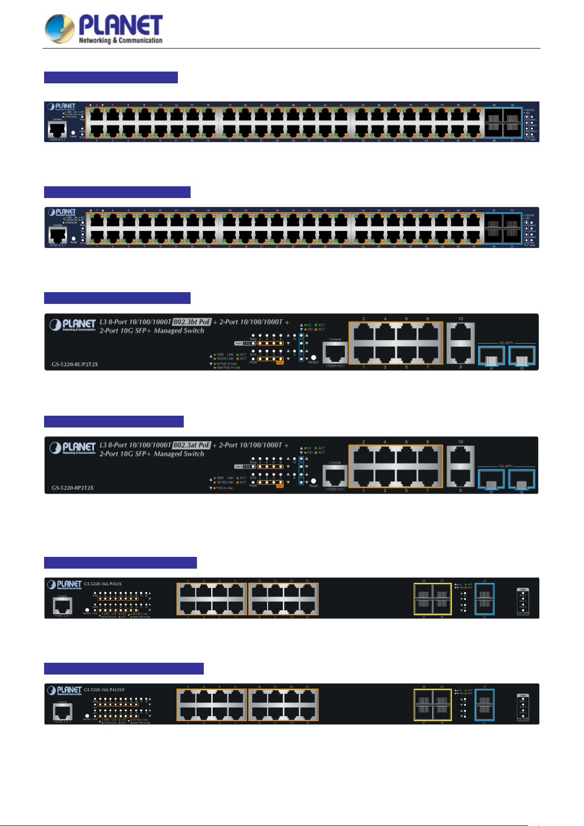
User’s Manual of GS-5220 PoE Series Managed Switch
40
GS-5220-48P4X Front Panel
GS-5220-48PL4XR Front Panel
GS-5220-8UP2T2X Front Panel
Figure 2-1-5: Front Panel of GS-5220-48P4X
Figure 2-1-6: Front Panel of GS-5220-48PL4XR
GS-5220-8P2T2X Front Panel
GS-5220-16UP4S2X Front Panel
Figure 2-1-7: Front Panel of GS-5220-8UP2T2X
Figure 2-1-8: Front Panel of GS-5220-8P2T2X
Figure 2-1-9: Front Panel of GS-5220-16UP4S2X
GS-5220-16UP4S2XR Front Panel
Figure 2-1-10: Front Panel of GS-5220-16UP4S2XR
Page 41

User’s Manual of GS-5220 PoE Series Managed Switch
41
GS-5220-24UP4X Front Panel
GS-5220-24UP4XR Front Panel
GS-5220-24UPL4X Front Panel
Figure 2-1-11: Front Panel of GS-5220-24UP4X
Figure 2-1-12: Front Panel of GS-5220-24UP4XR
Figure 2-1-13: Front Panel of GS-5220-24UPL4X
GS-5220-24UPL4XR Front Panel
Figure 2-1-14: Front Panel of GS-5220-24UPL4XR
■ Gigabit TP interface
10/100/1000BASE-T Copper, RJ45 twisted-pair: Up to 100 meters
■ 10 Gigabit SFP+ slot
1/10GBASE-SR/LR mini-GBIC slot, SFP+ (Small Factor Pluggable Plus) Transceiver module supports from 300 meters
(multi-mode fiber) up to 10 kilometers (single mode fiber)
■ Console port
The console port is a RJ45 port connector. It is an interface for connecting a terminal directly. Through the console port, it
provides rich diagnostic information including IP address setting, factory reset, port management, link status and system
setting. Users can use the attached DB9 to RJ45 console cable in the package and connect to the console port on the
device. After t he con nec tio n, users can run any terminal emulation program (Hyper Terminal, ProComm Plus, Telix,
Winterm and so on) to enter the startup screen of the device.
■ Reset button
The front panel of the GS-5220 PoE Series comes with a reset button designed for rebooting the Managed Switch without
turning off and on the power. The following is the summary table of reset button functions:
Page 42

User’s Manual of GS-5220 PoE Series Managed Switch
42
Reset Button Pressed and Released Function
< 5 sec: System Reboot Reboot the Managed Switch.
Reset the Managed Switch to Factory Default configuration.
The Managed Switch will then reboot and load the default
settings as shown below:
> 5 sec: Factory Default
The reset button of GS-5220 PoE Series is located at the front of the switch.
。 Default Username: admin
。 Default Password: admin
。 Default IP Address: 192.168.0.100
。 Subnet Mask: 255.255.255.0
。 Default Gateway: 192.168.0.254
Page 43

User’s Manual of GS-5220 PoE Series Managed Switch
43
2.1.2 LED Indications
The front panel LEDs indicate instant status of power and system status, Ring, port links and data activity; they help monitor
and troubleshoot when needed. Figures 2-1-17 and 2-1-30 show the LED indications of the Managed Switches.
GS-5220-24P4X(R)/GS-5220-24PL4X(R) LED Indication
Figure 2-1-17: Front Panel of GS-5220-24P4X
Figure 2-1-18: Front Panel of GS-5220-24P4XR
Figure 2-1-19: Front Panel of GS-5220-24PL4X
Figure 2-1-20: Front Panel of GS-5220-24PL4XR
System / Alert (GS-5220-24P4X and GS-5220-24PL4X)
LED Color Function
PWR Green
SYS Green
Ring Green
Lights to indicate that the Switch has power.
Lights to indicate the system is working.
Off to indicate the system is booting.
Lights to indicate that the ERPS Ring has been created successfully.
FAN 1 Red
FAN 2 Red
FAN 3 Red
PoE PWR Red
Lights to indicate that FAN1 is down.
Lights to indicate that FAN2 is down.
Lights to indicate that FAN3 is down.
Lights to indicate that the PoE power is down.
Page 44

User’s Manual of GS-5220 PoE Series Managed Switch
44
System / Alert (GS-5220-24P4XR and GS-5220-24PL4XR)
LED Color Function
AC Green
DC Green
SYS Green
Ring Green
FAN 1 Red
FAN 2 Red
FAN 3 Red
PoE PWR Red
10/100/1000BASE-T Interfaces (Port-1 to Port-24)
LED Color Function
Green
Ethernet
Amber
PoE Amber
Lights to indicate that the Switch has power from AC
Lights to indicate that the Switch has power from DC
Lights to indicate the system is working.
Off to indicate the system is booting.
Lights to indicate that the ERPS Ring has been created successfully.
Lights to indicate that FAN1 is down.
Lights to indicate that FAN2 is down.
Lights to indicate that FAN3 is down.
Lights to indicate that the PoE power is down.
Lights: To indicate that the port is operating at 1000Mbps.
Blinks: To indicate that the switch is actively sending or receiving data over that port.
Lights: To indicate that the port is operating at 10/100Mbps.
Blinks: To indicate that the switch is actively sending or receiving data over that port.
Lights: To indicate the port is providing DC in-line power
Off: To indicate the connected device is not a PoE Powered Device (PD)
100/1000BASE-SX/LX SFP Interfaces (Port-21 to Port-24)
LED Color Function
1000 Green
100 Amber
1/10GBASE-SR/LR SFP+ Interfaces (Port-25 to Port-28)
LED Color Function
10G Amber
1000 Green
Lights: To indicate that the port is operating at 1000Mbps.
Blinks: To indicate that the switch is actively sending or receiving data over that port.
Lights: To indicate that the port is operating at 100Mbps.
Blinks: To indicate that the switch is actively sending or receiving data over that port.
Lights: To indicate that the port is operating at 10Gbps.
Blinks: To i ndicate that the switch is actively sending or receiving data over that port.
Lights: To indicate that the port is operating at 1000Mbps.
Blinks: To i ndicate that the switch is actively sending or receiving data over that port.
Page 45

User’s Manual of GS-5220 PoE Series Managed Switch
45
GS-5220-48P4X(R)/GS-5220-48PL4X(R) LED Indication
Figure 2-1-21: Front Panel of GS-5220-48P4X
Figure 2-1-22: Front Panel of GS-5220-48PL4XR
System / Alert (GS-5220-48P4X)
LED Color Function
PWR Green
SYS Green
Ring Green
FAN 1 Red
FAN 2 Red
FAN 3 Red
PoE PWR Red
System / Alert (GS-5220-48PL4XR)
LED Color Function
AC Green
DC Green
SYS Green
Ring Green
FAN 1 Red
FAN 2 Red
Lights to indicate that the Switch has power.
Lights to indicate the system is working.
Off to indicate the system is booting.
Lights to indicate that the ERPS Ring has been created successfully.
Lights to indicate that FAN1 is down.
Lights to indicate that FAN2 is down.
Lights to indicate that FAN3 is down.
Lights to indicate that the PoE power is down.
Lights to indicate that the Switch has power from AC
Lights to indicate that the Switch has power from DC
Lights to indicate the system is working.
Off to indicate the system is booting.
Lights to indicate that the ERPS Ring has been created successfully.
Lights to indicate that FAN1 is down.
Lights to indicate that FAN2 is down.
FAN 3 Red
PoE PWR Red
10/100/1000BASE-T Interfaces (Port-1 to Port-48)
LED Color Function
Green
Ethernet
Amber
PoE Amber
Lights to indicate that FAN3 is down.
Lights to indicate that the PoE power is down.
Lights: To indicate that the port is operating at 1000Mbps.
Blinks: To indicate that the switch is actively sending or receiving data over that port.
Lights: To indicate that the port is operating at 10/100Mbps.
Blinks: To indicate that the switch is actively sending or receiving data over that port.
Lights: To indicate the port is providing DC in-line power
Off: To indicate the connected device is not a PoE Powered Device (PD)
Page 46

User’s Manual of GS-5220 PoE Series Managed Switch
46
Lights to indicate the Ring function is working.
Lights to indicate the system is working.
Off to indicate the system is booting.
Blinks:
1/10GBASE-SR/LR SFP+ Interfaces (Port-49 to Port-52)
LED Color Function
10G Amber
1000 Green
Lights: To indicate that the port is ope rating at 10Gbps.
Blinks: To i ndicate that the switch is actively sending or receiving data over that port.
Lights: To indicate that the port is operating at 1000/2500Mbps.
Blinks: To i ndicate that the switch is actively sending or receiving data over that port.
GS-5220-8UP2T2X Front Panel
Figure 2-1-23: Front Panel of GS-5220-8UP2T2X
■ System/Alert
LED Color Function
FAN Alert Red Lights to indicate that the fan is not working
Ring Green
SYS Green
Off to indicate the Ring function is not working.
PWR Green
■ PoE 10/100/1000BASE-T Interfaces (Port-1 to Port-8)
LED Color Function
1000
LNK/ACT
10/100
LNK/ACT
PoE In-Use
(bt)
PoE In-Use
(at/af)
■ 10/100/1000BASE-T Interfaces (Port-9 to Port-10)
LED Color Function
1000
LNK/ACT
10/100
LNK/ACT
Green
Amber
Green
Amber
Green
Amber
Lights to indicate the Switch has power.
Lights: To indicate the link through that port is successfully established at 1000Mbps.
To indicate that the switch is actively sending or receiving data over that port.
Lights: To indicate the link through that port is successfully established at 10/100Mbps.
Blinks: To indicate that the switch is actively sending or receiving data over that port.
Lights: To indicate the port is providing DC in-line power.
Off: To indicate the connected device is not a PoE Powered Device (PD)
Lights: To indicate the port is providing DC in-line power .
Off: To indicate the connected device is not a PoE Powered Device (PD)
Lights: To indicate the link through that port is successfully established at 1000Mbps.
Blinks: To indicate that the switch is actively sending or receiving data over that port.
Lights: To indicate the link through that port is successfully established at 10/100Mbps.
Blinks: To indicate that the switch is actively sending or receiving data over that port.
Page 47

User’s Manual of GS-5220 PoE Series Managed Switch
47
Lights to indicate the Ring function is working.
Lights to indicate the system is working.
Off to indicate the system is booting.
Lights
Lights
■ Per 1G/10G SFP+ Interfaces (Port-11 to Port-12)
LED Color Function
Indicating the port is running at 1Gbps speed and successfully established.
Indicating that the switch is actively sending or receiving data over that port.
Indicating the port is running at 10Gbps speed and successfully established.
Indicating that the switch is actively sending or receiving data over that port.
1G
LNK/ACT
10G
LNK/ACT
Green
Lights
Blinks
Lights
Amber
Blinks
GS-5220-8P2T2X Front Panel
Figure 2-1-24: Front Panel of GS-5220-8P2T2X
■ System/Alert
LED Color Function
Fan Alert Red Lights to indicate that the fan is not working
Ring Green
SYS Green
Off to indicate the Ring function is not working.
PWR Green
■ PoE 10/100/1000BASE-T Interfaces (Port-1 to Port-8)
LED Color Function
1000
LNK/ACT
10/100
LNK/ACT
PoE In-Use Amber
■ 10/100/1000BASE-T Interfaces (Port-9 to Port-10)
LED Color Function
1000
LNK/ACT
10/100
LNK/ACT
Green
Amber
Green
Amber
Lights to indicate the Switch has power.
Lights: To indicate the link through that port is successfully established at 1000Mbps.
Blinks: To indicate that the switch is actively sending or receiving data over that port.
: To indicate the link through that port is successfully established at 10/100Mbps .
Blinks: To indicate that the switch is actively sending or receiving data over that port.
Lights: To indicate the port is providing DC in-line power .
Off: To indicate the connected device is not a PoE Powered Device (PD)
Lights: To indicate the link through that port is successfully established at 1000Mbps.
Blinks: To indicate that the switch is actively sending or receiving data over that port.
: To indicate the link through that port is successfully established at 10/100Mbps.
Blinks: To indicate that the switch is actively sending or receiving data over that port.
Page 48

User’s Manual of GS-5220 PoE Series Managed Switch
48
■ Per 1G/10G SFP+ Interfaces (Port-11 to Port-12)
LED Color Function
Indicating the port is running at 1Gbps speed and successfully established.
Indicating that the switch is actively sending or receiving data over that port.
Indicating the port is running at 10Gbps speed and successfully established.
Indicating that the switch is actively sending or receiving data over that port.
1G
LNK/ACT
10G
LNK/ACT
Green
Lights
Blinks
Lights
Amber
Blinks
GS-5220-16UP4S2X/GS-5220-16UP4S2XR LED Indication
Figure 2-1-25: Front Panel of GS-5220-16UP4S2X
Figure 2-1-26: Front Panel of GS-5220-16UP4S2XR
System / Alert (GS-5220-16UP4S2X)
LED Color Function
PWR Green
SYS Green
Ring Green
FAN 1 Red
FAN 2 Red
FAN 3 Red
PoE PWR Red
System / Alert (GS-5220-16UP4S2XR)
LED Color Function
AC Green
DC Green
SYS Green
Ring Green
FAN 1 Red
Lights to indicate that the Switch has power.
Lights to indicate the system is working.
Off to indicate the system is booting.
Lights to indicate that the ERPS Ring has been created successfully.
Lights to indicate that FAN1 is down.
Lights to indicate that FAN2 is down.
Lights to indicate that FAN3 is down.
Lights to indicate that the PoE power is down.
Lights to indicate that the Switch has power from AC
Lights to indicate that the Switch has power from DC
Lights to indicate the system is working.
Off to indicate the system is booting.
Lights to indicate that the ERPS Ring has been created successfully.
Lights to indicate that FAN1 is down.
FAN 2 Red
FAN 3 Red
PoE PWR Red
Lights to indicate that FAN2 is down.
Lights to indicate that FAN3 is down.
Lights to indicate that the PoE power is down.
Page 49

User’s Manual of GS-5220 PoE Series Managed Switch
49
10/100/1000BASE-T Interfaces (Port-1 to Port-16)
LED Color Function
Green
Ethernet
Amber
Green
PoE
Amber
100/1000BASE-SX/LX SFP Interfaces (Port-17 to Port-20)
LED Color Function
1000 Green
100 Amber
Lights: To indicate that the port is operating at 1000Mbps.
Blinks: To indicate that the switch is actively sending or receiving data over that port.
Lights: To indicate that the port is operating at 10/100Mbps.
Blinks: To indicate that the switch is actively sending or receiving data over that port.
Lights: To indicate the port is providing DC in-line power with Ultra PoE mode.
Off: To indicate the connected device is not a PoE Powered Device (PD)
Lights:
Off: To indicate the connected device is not a PoE Powered Device (PD)
Lights: To indicate that the port is operating at 1000Mbps.
Blinks: To indicate that the switch is actively sending or receiving data over that port.
Lights: To indicate that the port is operating at 100Mbps.
Blinks: To indicate that the switch is actively sending or receiving data over that port.
To indicate the port is providing DC in-line power with End-span/Mid-span mode..
1/10GBASE-SR/LR SFP+ Interfaces (Port-21 to Port-22)
LED Color Function
10G Amber
1000 Green
Lights: To indicate that the port is operating at 10Gbps.
Blinks: To i ndicate that the switch is actively sending or receiving data over that port.
Lights: To indicate that the port is operating at 1000Mbps.
Blinks: To i ndicate that the switch is actively sending or receiving data over that port.
Page 50

User’s Manual of GS-5220 PoE Series Managed Switch
50
GS-5220-24UP(L)4X/ GS-5220-24UP(L)4XR LED Indication
Figure 2-1-27: Front Panel of GS-5220-24UP4X
Figure 2-1-28: Front Panel of GS-5220-24UP4XR
Figure 2-1-29: Front Panel of GS-5220-24UPL4X
Figure 2-1-30: Front Panel of GS-5220-24UPL4XR
System/ Alert (GS-5220-UP4X and GS-5220-24UPL4X)
LED Color Function
PWR Green
SYS Green
Ring Green
FAN 1 Red
FAN 2 Red
FAN 3 Red
PoE PWR Red
System / Alert (GS-5220-24UP4XR and GS-5220-24UPL4XR)
LED Color Function
AC Green
Lights to indicate that the Switch has power.
Lights to indicate the system is working.
Off to indicate the system is booting.
Lights to indicate that the ERPS Ring has been created successfully.
Lights to indicate that FAN1 is down.
Lights to indicate that FAN2 is down.
Lights to indicate that FAN3 is down.
Lights to indicate that the PoE power is down.
Lights to indicate that the Switch has power from AC
DC Green
SYS Green
Ring Green
FAN 1 Red
FAN 2 Red
FAN 3 Red
PoE PWR Red
Lights to indicate that the Switch has power from DC
Lights to indicate the system is working.
Off to indicate the system is booting.
Lights to indicate that the ERPS Ring has been created successfully.
Lights to indicate that FAN1 is down.
Lights to indicate that FAN2 is down.
Lights to indicate that FAN3 is down.
Lights to indicate that the PoE power is down.
Page 51

User’s Manual of GS-5220 PoE Series Managed Switch
51
10/100/1000BASE-T Interfaces (Port-1 to Port-24)
LED Color Function
Green
Ethernet
Amber
Green
PoE
Amber
100/1000BASE-SX/LX SFP Interfaces (Port-21 to Port-24)
LED Color Function
1000 Green
100 Amber
Lights: To indicate that the port is operating at 1000Mbps.
Blinks: To indicate that the switch is actively sending or receiving data over that port.
Lights: To indicate that the port is operating at 10/100Mbps.
Blinks: To indicate that the switch is actively sending or receiving data over that port.
Lights: To indicate the port is providing DC in-line power with Ultra PoE mode.
Off: To indicate the connected device is not a PoE Powered Device (PD)
Lights:
Off: To indicate the connected device is not a PoE Powered Device (PD)
Lights: To indicate that the port is operating at 1000Mbps.
Blinks: To indicate that the switch is actively sending or receiving data over that port.
Lights: To indicate that the port is operating at 100Mbps.
Blinks: To indicate that the switch is actively sending or receiving data over that port.
To indicate the port is providing DC in-line power with End-span/Mid-span mode..
1/10GBASE-SR/LR SFP+ Interfaces (Port-25 to Port-28)
LED Color Function
10G Amber
1000 Green
Lights: To indicate that the port is operating at 10Gbps.
Blinks: To i ndicate that the switch is actively sending or receiving data over that port.
Lights: To indicate that the port is operating at 1000Mbps.
Blinks: To i ndicate that the switch is actively sending or receiving data over that port.
Page 52

User’s Manual of GS-5220 PoE Series Managed Switch
52
Switch from being damaged by unregulated
2.1.3 Switch Rear Panel
The rear panel of the Managed Switch consists of the AC/DC inlet power socket. Figures 2-1-31 to 2-1-33 show the rear pane l s
of the Managed Switches.
GS-5220-24P4X/24PL4X/48P4X/16UP4S2X/24UP4X/24UPL4X Rea r Panel
Figure 2-1-31: Rear Panel of GS-5220-24P(L)4X/48P4X/16UP4S2X/24UP(L)4X
GS-5220-8UP2T2X/GS-5220-8P2T2X Rear Pan e l
Figure 2-1-32: Rear Panel of GS-5220-8UP2T2X/GS-5220-8P2T2X
GS-5220-24P4XR/24PL4XR/48PL4XR/16UP4S2XR/24UP4XR/24UPL4XR R ear Pan el
Figure 2-1-33: Rear Panel of GS-5220-24P(L)4XR/48PL4XR/16UP4S2XR/24UP(L)4XR
■ AC Power Receptacle
For compatibility with electrical voltages in most areas of the world, the Managed Switch’s power supply can automatically
adjust line power in the range of 100-240V AC and 50/60 Hz.
Plug the female end of the power cord f irm ly int o t he receptacle on the re ar p anel of the Managed Switch and the other end
of the power cord into an electrical outlet and the power will be ready.
The device is a power-required device, which means it will not work till it is powered. If your networks
should be active all the time, please consider using UPS (Uninterrupted Power Supply) for your device.
Power Notice:
It will prevent you from network data loss or network downtime. In some areas, inst all ing a surge
suppression device may also help to protect your Managed
surge or current to the Switch or the power adapter.
Page 53

User’s Manual of GS-5220 PoE Series Managed Switch
53
5220 PoE series red unda nt
■ DC Power Connector
The following GS-5220 PoE series supports redundant power system (PoE not included ):
GS-5220-24P4XR
GS-5220-24PL4XR
GS-5220-48PL4XR
GS-5220-16UP4S2XR
GS-5220-24UP4XR
GS-5220-24UPL4XR
The rear panels of the above models have a power switch and a DC power connector, where the latter accepts DC power
input voltage from 36V to 60V DC. Connect the power cable to the Managed Switch at the input terminal block. The size of
the two screws in the terminal block is M3.5.
Warning:
Figure 2-1-34: Rear Panel of GS-5220 PoE series Redundant Power Models
Before connecting the DC power cable to the in put ter minal block of the GSpower models, make sure that the power switch is in the “OFF” position and the DC power is OFF.
Page 54

User’s Manual of GS-5220 PoE Series Managed Switch
54
, the
Chapter 1,
45 tips. For more
2.2 Installing the Switch
This section describes how to install your Managed Switch and make connections to the Managed Switch. Please read the
following topics and perform the procedure s in the order being pre sen ted. To install your Managed Switch on a desktop or shelf,
simply complete the following steps.
In the installation steps below, this manual uses the GS-5220-48T4X as an example. However
steps for PLANET GS-5220 PoE series are similar.
2.2.1 Desktop Installation
To install the Managed Switch on desktop or shelf, please follow these steps:
Step 1: Attach the rubber feet to the recessed areas on the bottom of the Managed Switch.
Step 2: Place the Managed Switch on the desktop or the shelf near an AC power source, as shown in Figure 2-2-1.
Figure 2-2-1: Place the Managed S w it ch on the Desktop
Step 3: Keep enough ventilation space between the Managed Switch and the surrounding objects.
When choosing a location, please keep in mind the environmental restrictions discussed in
Section 4, and specifications.
Step 4: Connect the Managed Switch to network devices.
Connect one end of a standard network cable to the 10/100/1000 RJ45 ports on the front of the Managed Switch.
Connect the other end of the cable to the network devices such as printer server, workstation or router.
Connection to the Managed S w itch require s UTP C ategory 5 e network cabling with RJ
information, please see the Cabling Specification in Appendix A.
Page 55

User’s Manual of GS-5220 PoE Series Managed Switch
55
mounting brackets. Damage caused to the parts by
Step 5: Supply power to the Managed Switch.
Connect one end of the power cable to the Managed Switch.
Connect the power plug of the power cable to a standard wall outlet.
When the Managed Switch receives power, the Power LED should remain solid Green.
2.2.2 Rack Mounting
To inst all the Managed Switch in a 19-inch standard rack, please follow the instructions described below.
Step 1: Place the Managed Switch on a hard flat surface, with the front panel positioned towards the front side.
Step 2: Attach the rack-mount bracket to each side of the Managed Switch with supplied screws attached to the package.
Figure 2-2-2 shows how to attach brackets to one side of the Managed Switch.
Figure 2-2-2: Attach Brackets to the Managed Switch.
You must use the screws supplied with the
using incorrect screws would invalidate the warranty.
Step 3: Secure the brackets tightly.
Step 4: Follow the same steps to attach the second bracket to the opposite side.
Step 5: After the brackets are attac hed t o the Managed Switch, use suitable screws to securely attach the brackets to the rack,
as shown in Figure 2-2-3.
Page 56

User’s Manual of GS-5220 PoE Series Managed Switch
56
Figure 2-2-3: Mounting Managed Switch in a Rack
Step 6: Proceed with Steps 4 and 5 of session 2.2.1 Desktop Installation to connect the network cabling and supply power to
the Managed Switch.
2.2.3 Installing the SFP/SFP+ Transceiver
The sections describe how to insert an SFP/SFP+ transceiver into an SFP/SFP+ slot. The SFP/SFP+ transceivers are
hot-pluggable and hot-sw appa ble. You can plug in and out the transceiver to/from any SFP/SFP+ port without having to power
down the Managed Switch, as the Figure 2-2-4 shows..
Figure 2-2-4: Plug-in the SFP/SFP+ Transceiver
Page 57

User’s Manual of GS-5220 PoE Series Managed Switch
57
Interface
Approved PLANET SFP/SFP+ Transceivers
PLANET Managed Switch supports both singl e mode and multi-mode SFP/SFP+ transceivers. The following list of approved
PLANET SFP/SFP+ transceivers is correct at the time of publication:
Fast Ethernet Transceiver (100BASE-X SFP)
Model Speed (Mbps)
MFB-FX 100 LC Multi Mode 2km 1310nm 0 ~ 60 degrees C
MFB-F20 100 LC Single Mode 20km 1310nm 0 ~ 60 degrees C
MFB-F40 100 LC Single Mode 40km 1310nm 0 ~ 60 degrees C
MFB-F60 100 LC Single Mode 60km 1310nm 0 ~ 60 degrees C
MFB-F120 100 LC Single Mode 120km 1550nm 0 ~ 60 degrees C
MFB-TFX 100 LC Multi Mode 2km 1310nm -40 ~ 75 degrees C
MFB-TF20 100 LC Single Mode 20km 1550nm -40 ~ 75 degrees C
Connector Interface
Fiber Mode Distance Wavelength (nm) Operating Temp.
Fast Ethernet T ran sc eiv er (100BASE-BX, Single Fiber Bi-directional SFP)
Model Speed (Mbps) Connector Interface Fiber Mode Distance Wavelength (TX/RX) Operating Temp.
MFB-FA20 100 WDM(LC) Single Mode 20km 1310nm/1550nm 0 ~ 60 degrees C
MFB-FB20 100 WDM(LC) Single Mode 20km 1550nm/1310nm 0 ~ 60 deg ree s C
MFB-TFA20 100 WDM(LC) Single Mode 20km 1310nm/1550nm -40 ~ 75 degrees C
MFB-TFB20 100 WDM(LC) Single Mode 20km 1550nm/1310nm -40 ~ 75 degrees C
MFB-TFA40 100 WDM(LC) Single Mode 40km 1310nm/1550nm -40 ~ 75 degrees C
MFB-TFB40 100 WDM(LC) S i ng le Mod e 40km 1550nm/1310nm -40 ~ 75 degrees C
Gigabit Ethernet Transceiver (1000BASE-X SFP)
Model DDM Speed (Mbps)
MGB-GT -- 1000 Copper -- 100m --
MGB-SX(V2) YES 1000 LC Multi Mode 550m 850nm
MGB-SX2(V2) YES 1000 LC Multi Mode 2km 1310nm
MGB-LX(V2) YES 1000 LC Single Mode 20km 1310nm
MGB-L40 YES 1000 LC Single Mode 40km 1310nm
MGB-L80 YES 1000 LC Single Mode 80km 1550nm
MGB-L120(V2) YES 1000 LC Single Mode 120km 1550nm
MGB-TSX YES 1000 LC Multi Mode 550m 850nm
MGB-TSX2 YES 1000 LC Multi Mode 2km 1310nm
MGB-TLX(V2) YES 1000 LC Single Mode 20km 1310nm
MGB-TL40 YES 1000 LC Single Mode 40km 1310nm
MGB-TL80 YES 1000 LC Single Mode 80km 1550nm
Connector
Fiber Mode Distance Wavelength (nm) Operating Temp.
0 ~ 60 ℃
0 ~ 60 ℃
0 ~ 60 ℃
0 ~ 60 ℃
0 ~ 60 ℃
0 ~ 60 ℃
0 ~ 60 ℃
-40 ~ 75 ℃
-40 ~ 75 ℃
-40 ~ 75 ℃
-40 ~ 75 ℃
-40 ~ 75 ℃
Page 58
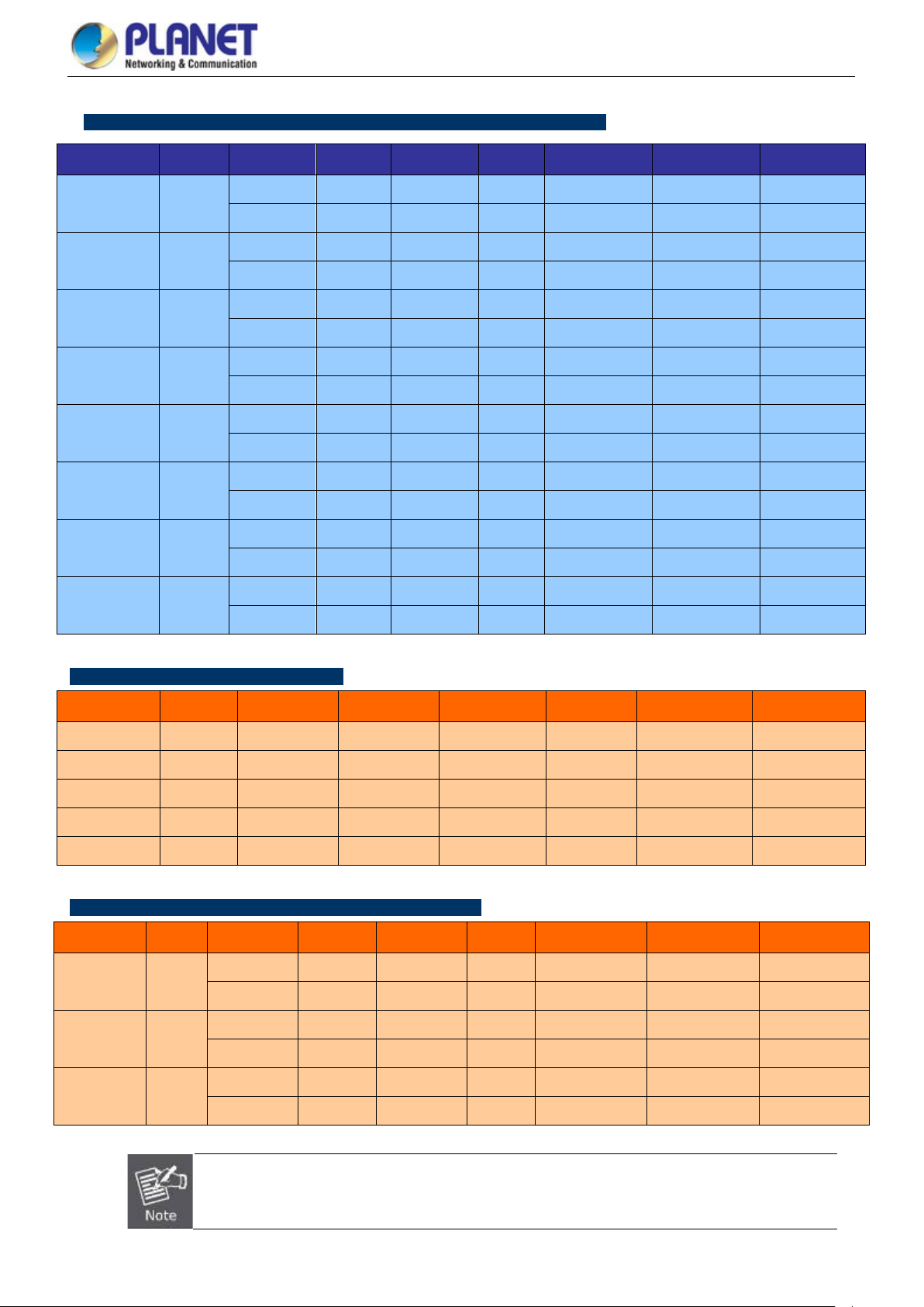
User’s Manual of GS-5220 PoE Series Managed Switch
58
(Mbps)
Connector
Interface
Interface
Interface
Gigabit Ethernet Transceiver (1000BASE-BX, Single Fiber Bi-directional SFP)
Model DDM Speed
MGB-LA10(V2)
YES
MGB-LB10(V2)
MGB-LA20(V2)
YES
MGB-LB20(V2)
MGB-LA40(V2)
YES
MGB-LB40(V2)
MGB-LA80
YES
MGB-LB80
MGB-TLA10(V2)
YES
MGB-TLB10(V2)
MGB-TLA20
YES
MGB-TLB20
MGB-TLA40
YES
MGB-TLB40
MGB-TLA80
YES
MGB-TLB80
Fiber Mode Distance Wavelength (TX) Wavelength (RX) Operating Temp.
1000 WDM(LC) Single Mode 10km 1310nm 1550nm
1000 WDM(LC) Single Mode 10km 1550nm 1310nm
1000 WDM(LC) Single Mode 20km 1310nm 1550nm
1000 WDM(LC) Single Mode 20km 1550nm 1310nm
1000 WDM(LC) Single Mode 40km 1310nm 1550nm
1000 WDM(LC) Single Mode 40km 1550nm 1310nm
1000 WDM(LC) Single Mode 80km 1490nm 1550nm
1000 WDM(LC) Single Mode 80km 1550nm 1490nm
0 ~ 60 ℃
0 ~ 60 ℃
0 ~ 60 ℃
0 ~ 60 ℃
0 ~ 60 ℃
0 ~ 60 ℃
0 ~ 60 ℃
0 ~ 60 ℃
-40 ~ 75 ℃
-40 ~ 75 ℃
-40 ~ 75 ℃
-40 ~ 75 ℃
-40 ~ 75 ℃
-40 ~ 75 ℃
-40 ~ 75 ℃
-40 ~ 75 ℃
10Gbps SFP+ (10G Ethernet/10GBASE)
Model DDM Speed (Mbps)
MTB-RJ - 10G Copper - 30m -
MTB-SR YES 10G LC Multi Mo d e Up to 300m 850nm
MTB-LR YES 10G LC Single Mode 10km 1310nm
MTB-TSR YES 10G LC Multi Mode Up to 300m 850nm
MTB-TLR YES 10G LC Single Mode 10km 1310nm
Connector
Fiber Mode Distance Wavelength (nm) Operating Temp.
10Gbps SFP+ (10GBASE-BX, Single Fiber Bi-directional SFP)
Model DDM Speed (Mbps)
MTB-LA20
YES
MTB-LB20
MTB-LA40
YES
MTB-LB40
MTB-LA60
YES
MTB-LB60
10G WDM(LC) S ing le Mod e 20km 1270nm 1330nm
10G WDM(LC) S ing le Mod e 20km 1330nm 1270nm
10G WDM(LC) S ing le Mod e 40km 1270nm 1330nm
10G WDM(LC) S ing le Mod e 40km 1330nm 1270nm
10G WDM(LC) S ing le Mod e 60km 1270nm 1330nm
10G WDM(LC) S ing le Mod e 60km 1330nm 1270nm
Connector
Fiber Mode Distance Wavelength (TX) Wavelength (RX) Operating Temp.
0 ~ 70 ℃
0 ~ 60 ℃
0 ~ 60 ℃
-40 ~ 75 ℃
-40 ~ 75 ℃
0 ~ 60 ℃
0 ~ 60 ℃
0 ~ 60 ℃
0 ~ 60 ℃
0 ~ 60 ℃
0 ~ 60 ℃
It is recommended to use PLANET SFP/SFP+ on the Managed Switch. If you insert an SFP/SFP+
transceiver that is not supported, the Managed Switch will not recognize it.
Page 59

User’s Manual of GS-5220 PoE Series Managed Switch
59
1. Before we connect the GS-5220 PoE series to the other network device, we have to make sure both sides of the SFP
transceivers are with the same media type, for example: 1000BASE-SX to 1000BASE-SX, 1000BASE-LX to
1000BASE-LX.
2. Check whether the fiber-optic cabl e type matches with the SFP transceiver requirement.
To connect to 1000BASE-SX SFP transceiver, please use the multi-mode fiber cable with one side being the male
duplex LC connector type.
To connect to 1000BASE-LX SFP transceiver, please use the single-mode fiber cable with one side being the male
duplex LC connector type.
Connecting the Fiber Cable
1. Insert the duplex LC connector into the SFP/SFP+ transceiver.
2. Connect the other end of the cable to a device with SFP/SFP+ transceiver installed.
3. Check the LNK/ACT LED of the SFP/SFP+ slot on the front of the Managed Switch. Ensure that the SFP/SFP+
transceiver is operating correctly.
4. Check the Link mode of the SFP/SFP+ port if the link fails. To function with some fiber-NICs or Media Converters, user
has to set the port Link mode to “10G Force”, or “1000M Force”.
Removing the Transceiver Module
1. Make sure there is no network activity anymore.
2. Remove the Fiber-Optic Cable gently.
3. Lift up the lever of the MGB module and turn it to a horizontal positi on.
4. Pull out the module gently through the lever.
Figure 2-2-5: How to Pull Out the SFP/SFP+ Transceiver
Page 60

User’s Manual of GS-5220 PoE Series Managed Switch
60
a horizontal
Never pull out the module without lifting up the lever of the module and turning it to
position. Directly pulling out the module could damage the module and the SFP/SFP+ module
slot of the Managed Switch.
Page 61

User’s Manual of GS-5220 PoE Series Managed Switch
61
3. SWITCH MANAGEMENT
This chapter explains the methods that you can use to configure management access to the Managed Switch. It describes the
types of management applications and the communication and management protocols that deliver data between your
management device (workstation or personal computer) and the system. It also contains information about port connection
options.
This chapter covers the following topics:
Requirements
Management Access Overview
Administration Console Access
Web Management Access
SNMP Access
Standards, Protocols, and Related Reading
3.1 Requirements
Workstations running Windows 2000/XP, 2003, Vista/7/8/10, 2008, MAC OS9 or later, or Linux, UNIX , or other
platforms compatible with TCP/IP protocols.
Workstation is installed with Ethernet NIC (Network Interface Card)
Serial Port connect (Terminal)
• The above PC with COM Port (DB9/RS-232) or USB-to-RS232 converter
Ethernet Port connect
• Network cables - Use standard network (UTP) cables with RJ45 connectors.
The above workstation is installed with Web Browser and JAVA runtime environment plug-in
It is recommended to use Mozilla Firefox 1.5 or above to access Managed Switch.
Page 62

User’s Manual of GS-5220 PoE Series Managed Switch
62
3.2 Management Access Overview
The Managed Switch gives you the flexibility to access and manage it using any or all of the following methods:
An administration console
Web browser interface
An external SNMP-based network management application
The administration console and Web browser interface support are embedded in the Managed Sw itch software and are
available for immediate use. Each of these management methods has their own advantages. Table 3-1 compares the three
management methods.
Method Advantages Disadvantages
Console
Web Browser
SNMP Agent
• No IP address or subnet needed
• Text-based
• Telnet functionality and HyperTerminal
built into Windows
95/98/NT/2000/ME/XP operating
systems
• Secure
• Ideal for configuring the switch remotely
• Compatible with all popular browsers
• Can be accessed from any location
• Most visually appealing
• Communicates with switch functions at
the MIB level
• Based on open standards
• Must be near the switch or use dial-up
connection
• Not convenient for remote users
• Modem connection may prove to be unreliable
or slow
• Security can be compro mis ed (hac kers need
only know the IP address and subnet mask)
• May encounter lag times on poor connections
• Requires SNMP manager software
• Least visually appea lin g of all thr ee meth ods
• Some settings require calculations
• Security can be compro mis ed (hac kers need
only know the community name)
Table 3-1: Comparison of Management Methods
Page 63

User’s Manual of GS-5220 PoE Series Managed Switch
63
3.3 Administration Console
The administration console is an interna l, chara cter -oriented, and command line user interface for performing system
administration such as displaying statistics or changing option settings. Using this method, you can view the administration
console from a terminal, personal computer, Apple Macintosh, or workstation connected to the Managed Switch's console
(serial) port.
Figure 3-1: Console Management
Direct Access
Direct access to the administration console is achieved by directly connecting a terminal or a PC equipped with a
terminal-emulation program (such as HyperTerminal) to the Managed Switch console (serial) port. When us ing this
management method, a straight DB9 RS232 cable is required to connect the switch to the PC. After making this connection,
configure the terminal-emulation program to use the following parameters:
The default parameters are:
115200 bps
8 data bits
No parity
1 stop bit
Figure 3-2: Terminal Parameter Settings
Page 64

User’s Manual of GS-5220 PoE Series Managed Switch
64
You can change these settings, if desired, after you log on. This management method is often preferred because you can
remain connected and monitor the system during system reboots. Also, certain error messages are sent to the serial port,
regardless of the interface through which the associated action was initiated. A Macintosh or PC attachment can use any
terminal-emulation program for connecting to the terminal serial port. A workstation attachment under UNIX can use an
emulator such as TIP.
3.4 Web Management
The Managed Switch offers management features that allow users to manage the Managed Switch from anywhere on the
network through a standard browser such as Microsoft Internet Explorer. After you set up your IP address for the switch, you
can access the Managed Switch's Web interface applications directly in your Web browser by entering the IP address of the
Managed Switch.
Figure 3-1-3: Web Management
You can then use your Web browser to list and manag e the M anaged Switch configuration param eter s from one c entral lo cation ,
just as if you were directly connected to the Managed Switch's console port. Web Management requires either Microsoft
Internet Explorer 7.0 or later, Safari or Mozilla Firefox 1.5 or later.
Figure 3-1-4: Web Main Screen of Managed Switch
Page 65

User’s Manual of GS-5220 PoE Series Managed Switch
65
3.5 SNMP-based Network Management
You can use an external SNMP-based application to configure and manage the Managed Switch, such as SNMP Network
Manager, HP Openview Network Node Management (NNM) or What’s Up Gold. This management method requires the SNMP
agent on the switch and the SNMP Network Management Station to use the same community string. This management
method, in fact, uses two community strings: the get community string and the set community string. If the SNMP Net-work
management Station only knows the set community string, it can read and write to the MIBs. However, if it only knows the get
community string, it can only read MIBs. The default getting and setting community strings for the Managed Switch is public.
Figure 3-1-5: SNMP Management
3.6 PLANET Smart Discovery Utility
For easily listing the Managed Switch in your Ethernet environment, the Planet Smart Discovery Utility from user’s manual
CD-ROM is an ideal solution. The following install ation instructions are to guide you to running the Planet Smart Discovery
Utility.
1. Deposit the Planet Smart Discovery Utility in administrator PC.
2. Run this utility as the following screen appears.
Figure 3-1-6: Planet Smart Discovery Utility Screen
Page 66

User’s Manual of GS-5220 PoE Series Managed Switch
66
different LAN card
If there are two LAN cards or above in the same administrator PC, choose a
by using the “Select Adapter” tool.
3. Press the “Refresh” button for the currently connected devices in the discovery list as the screen shows below:
Figure 3-1-7: Planet Smart Discovery Utility Screen
1. This utility shows all necessary information from the devices, such as MAC address, device name, firmware version, and
device IP subnet address. It can also assign new password, IP subnet address and description to the devices.
2. After setup is completed, press the “Update Device”, “Update Multi” or “Update All” button to take effect. The functions of
the 3 buttons above are shown below:
Update Device: use current setting on one single device.
Update Multi: use current setting on choose multi-devices.
Update All: use current setting on whole devices in the list.
The same functions mentioned above also can be found in “Option” tools bar.
3. To click the “Control Packet Force Broadcast” function, it allows you to assign a new setting value to the Web Smart
Switch under a different IP subnet address.
4. Press the “Connect to Device” button and the Web login screen appears in Fi gure 3-1-4.
5. Press the “Exit” button to shut down the Planet Smart Discovery Utility.
Page 67

User’s Manual of GS-5220 PoE Series Managed Switch
67
0 or later version does not allow Java Applets to open sockets. The user has to explicitly
4. WEB CONFIGURATION
This section introduces the configuration and functions of the Web-based management from Managed Switch.
About Web-based Management
The Managed Switch offers management features that allow users to manage the Managed Switch from anywhere on the
network through a standard browser such as Microsoft Internet Explorer.
The Web-based Management supports Inter net Explorer 8.0. It is based on Java Applets with an aim to reduce network
bandwidth consumption, enhance access speed and present an easy viewing screen.
By default, IE7.
modify the browser setting to enable Java Applets to use network ports.
The Managed Switch can be configured through an E th ernet connection, making sur e the manager PC must be set to the same
IP subnet address with the Managed Switch.
For example, the default IP address of the Managed Switch is 192.168.0.100, then the manager PC should be set to
192.168.0.x (where x is a number between 1 and 254, except 100), and the default subnet mask is 255.2 55.2 55.0.
If you have changed the default IP addres s of the Managed Switch to 192.168 . 1.1 with subnet mask 255.255.255.0 via con sol e ,
then the manager PC should be set to 192.168.1.x (where x is a number between 2 and 254) to do the relative configuration on
manager PC.
Figure 4-1-1: Web Management
Logging on to the Managed Switch
1. Use Internet Explorer 7.0 or above Web browser. Enter the factory-default IP addr es s to acces s the Web int erf ace . The
factory-default IP address is shown as follows:
http://192.168.0.100
Page 68

User’s Manual of GS-5220 PoE Series Managed Switch
68
2. When the following login screen appears, please enter the default username "admin" with password “admin” (or the
username/password you have changed via console) to log in the main screen of Managed Sw itch. T he login screen in
Figure 4-1-2 appears.
Figure 4-1-2: Login Screen
Default User name: admin
Default Password: admin
After entering the username and password, the main screen appears as shown in Figure 4-1-3.
Figure 4-1-3: Web Main Page
Now , y ou can use the Web management interf ace t o co ntin u e t he sw itch m ana gem ent or manage the Managed Switch by Web
interface. The Switch Menu on the left of the web page lets you access all the commands and statistics the Managed Switch
provides.
Page 69

User’s Manual of GS-5220 PoE Series Managed Switch
69
1. It is recommended to use Mozilla Firefox 1.5 or above to access Managed Switch.
2. The changed IP address takes effect immediately after clicking on the Save button. You need to
use the new IP address to access the Web interface.
3. For security reason, please change and memorize the new password after this first setup.
4. Only accept command in lowercase letter under web interface.
4.1 Main Web Page
The Managed Switch provides a Web-based browser interface for configuring and managi n g it. This interface allows you to
access the Managed Switch using the Web browser of your choice. This chapter describes how to use the Managed Switch’s
Web browser interface to configure and manage it.
Main Functions
Copper Port Link
SFP/SFP+ Port Link
Help Button
Figure 4-1-4: Web Main Page
Panel Display
The web agent displays an image of the Managed Switch’s ports. T he M ode can be set to display dif f er ent information for the
ports, including Link up or Link down. Clicking on the image of a port opens the Port Statistics page.
The port status is illustrated as follows:
State Disabled Down Link
RJ45 Ports
SFP Ports
Main Menu
Using the onboard w eb a gent , y ou ca n d efi ne system parameters, ma nag e a nd co ntr ol th e Managed Switch, and al l its ports, or
monitor network conditions. Via the Web-Management, the administrator can set up the Managed Switch by selecting the
functions those listed in the Main Function. The screen in Figure 4-1-5 appears.
Page 70

User’s Manual of GS-5220 PoE Series Managed Switch
70
Figure 4-1-5: Managed Switch Main Functions Menu
Page 71

User’s Manual of GS-5220 PoE Series Managed Switch
71
on
This page displays the status of the IP protocol layer. The status is defined
e IP routes and the neighbor cache (ARP cache)
4.2 System
Use the System menu ite ms to display and configur e ba sic ad ministra tive d etails of the M anaged Switch. Under the System, the
following topics are provided to configure and view the system information. This section has the following items:
■ System Information The Managed Switch system information is provid ed here.
■ IP Configuration Configure the IP
this page.
■ IP Status
by the IP interfaces, th
status.
■ Users Configuration
■ Privilege Levels
■ NTP Configuration Configure NTP server on this page.
■ Time Configuration Configure time parameter on this page.
■ UPnP Configure UPnP on this page.
■ DHCP Relay Configure DHCP Relay on this page.
■ DHCP Relay Statistics This page provides statistics for DHCP relay.
■ CPU Load This page displays the CPU load, using an SVG graph.
■ System Log The system log information of the Managed Switch system is provided here.
■ Detailed Log The detailed log informati on of the Managed Switch system is provided here .
This page provides an overview of the current users. Currently the only way
to login as another user on the web server is to close and reopen the
browser.
This page provides an overview of the privilege levels.
v4/IPv6 interface and IP routes of the Managed Switch
■ Remote Syslog Configure remote syslog on this page.
■ SMTP Configuration Configure SMTP parameters on this page.
■ SNMP Configure SNMP parameters on this page
■ RMON Configure the RMON parameters on this page
■ DHCP server
Configure the DHCP server on this page
Page 72

User’s Manual of GS-5220 PoE Series Managed Switch
72
4.2.1 Management
4.2.1.1 System Information
The System Information page provides information for the current device information. System Information page helps a switch
administrator to identify the hardware MAC address, software version and system upt ime. The screen in Figure 4-2-1 appears.
Figure 4-2-1-1: System Information Page Screenshot
The page includes the following fields:
Object Description
• Contact
• Name
• Location
• MAC Address
• Temperature
• Power Status
• System Date
• System Uptime
• Software Version
• Software Date
The system contact configured in SNMP | System Information | System Contact.
The system name configured in SNMP | System Information | System Name.
The system location configured in SNMP | System Information | System Location.
The MAC Address of this Managed Switch.
Indicates chipset temperature.
The status of power input (AC and DC)
The current (GMT) system time and date. The system time is obtained through the
configured NTP Server, if any.
The period of time the device has been operational.
The software version of the Managed Switch.
The date when the Managed Switch software was produced.
Buttons
Auto-refresh : Check this box to refresh the page automatically. Automatic refresh occurs every 3 seconds.
Page 73

User’s Manual of GS-5220 PoE Series Managed Switch
73
4.2.1.2 IP Configuration
The IP Configuration includes the IP Configuration, IP Interface and IP Routes. The configured column is used to view or
change the IP configuration. The maximum number of interfaces supported is 128 and the maximum number of routes is 128.
The screen in Figure 4-2-2 appears.
Figure 4-2-1-2: IP Configuration Page Screenshot
The current column is used to show the active IP configuration.
Object Description
• IP Configurations Domain Name
Mode
DNS Server
Configure the Switch Domain Name
Configure whether the IP stack should act as a Host or a Router. In
Host mode, IP traffic between interfaces will not be routed. In Router
mode traffic is routed between all interfaces.
This setting controls the DNS name resolution done by the switch. The
following modes are supported:
No DNS server
No DNS server will be used..
Configure IPv4 or IPv6
Explicitly specify the name of local domain.
Make sure the configured domain name meets your organization's
given domain.
From an y DHCPv6 interfaces
The first domain name offered from a DHCPv6 lease to a
DHCPv6-enabled interface will be used.
From this DHCPv6 interface
Specify from which DHCPv6-enabled interface a provided domain
name should be preferred.
Page 74

User’s Manual of GS-5220 PoE Series Managed Switch
74
The destination IP network or host address of this route. Valid format is
DNS Proxy
• IP Interface Delete
VLAN
IPv4
DHCP
IPv4 Address
DHCPv6 Enable
Enabled
Fallback
Current
Lease
Mask Length
When DNS proxy is enabled, system will relay DNS requests to the
currently configured DNS server, and reply as a DNS resolver to the
client devices on the network.
Select this option to delete an existing IP interface.
The VLAN associated with the IP interface. Only ports in this VLAN will
be able to access the IP interface. This field is only available for input
when creating a new interface.
Enable the DHCP client by checking this box.
The number of seconds for trying to obtain a DHCP lease.
For DHCP interfaces with an active lease, this column shows the
current interface address, as provided by the DHCP server.
Provide the IP address of this Managed Switch in dotted decimal
notation.
The IPv4 network mask, in number of bits (prefix length). Valid values
are between 0 and 30 bits for an IPv4 address.
Enable the DHCPv6 clien t by c hecking this box . If thi s opt ion i s enable d,
IPv6 Address
• IP Routes Delete
Network
Rapid
Commit
Current
Lease
Mask Length
the system will configure the IPv6 address of the interface using the
DHCPv6 protocol
Enable the DHCPv6 Rapid-C o mmit option by checking this box. If this
option is enabled, the DHCPv6 client terminates the waiting process as
soon as a Reply message with a Rapid Commit option is received.
This option is only manageable when DHCPv6 client is enabled.
For DHCPv6 interface with an active lease, this column shows the
interface address provided by the DHCPv6 server
Provide the IP address of this Managed Switch. An IPv6 addr ess is in
128-bit records represented as eight fields of up to four hexadecimal
digits with a colon separating each field (:).
The IPv6 network mask, in number of bits (prefix length). Valid values
are between 1 and 128 bits for an IPv6 address.
Select this option to delete an existing IP route.
dotted decimal notation or a valid IPv6 notation. A default route can use
the value 0.0.0.0 or IPv6 :: notation.
Mask Length
Gateway
Next Hop VLAN
The destination IP network or host mask, in number of bits (prefix
length).
The IP address of the IP gateway. Valid format is dotted decimal
notation or a valid IPv6 notation. Gateway and Network must be of the
same type.
The VLAN ID (VID) of the specific IPv6 interface associated with the
Page 75

User’s Manual of GS-5220 PoE Series Managed Switch
75
gateway.
Buttons
: Click to add a new IP interface. A maximum of 128 interfaces are supported.
: Click to add a new IP route. A maximum of 32 routes are supported.
: Click to apply changes.
: Click to undo any changes made locally and revert to previously saved values.
4.2.1.3 IP Status
IP Status displays the status o f the IP protoc ol lay er. The status is defined by the IP interfaces, the IP routes and the neighbor
cache (ARP cache) status. T he screen in Figure 4-2-1-3 appears.
Figure 4-2-1-3: IP Status Page Screenshot
The page includes the following fields:
Object Description
• IP Interfaces
• IP Routes
Interface The name of the interface.
Type
Address The current address of the interface (of the given type).
Status The status flags of the interface (and/or address).
Network The destination IP network or host address of this route.
The address type of the entry. This may be LINK or IPv4.
Page 76

User’s Manual of GS-5220 PoE Series Managed Switch
76
Gateway The gateway address of this route.
Status The status flags of the route.
• Neighbor Cache
Buttons
Auto-refresh : Check this box to refresh the page automatically. Automatic refresh occurs every 3 seconds.
: Click to refresh the page.
IP Address The IP address of the entry.
Link Address The Link (MAC) address f or which a binding to t he I P address given exists.
4.2.1.4 Users Configuration
This page provides an overview of the current users. Currently the only way to login as another user on the web server is to
close and reopen the browser. After setup is completed, press the “Apply” butt on to take ef f ect. P lease login w eb interfa ce w ith
new user name and password; the screen in Fi gur e 4-2-4 appears.
Figure 4-2-1-4: Users Configuration Page Screenshot
The page includes the following fields:
Object Description
• User Name
• Privilege Level
The name identifying the user. This is also a link to Add/Edit User.
The privilege level of the user.
The allowed range is 1 to 15. If the privilege level value is 15, it can access all
groups, i.e. that is granted the full control of the device. But other values need to
refer to each group privileg e le v el. User 's priv i lege should be the same or greate r
than the group privilege level to have the access to that group.
By default setting, most groups privilege level 5 has the read-only acce ss and
privilege level 10 has the read-write access. And the system maintenance
(software upload, factory defaults and etc.) needs user privilege level 15.
Generally, the privilege level 15 can be used for an administrator account,
privilege level 10 for a standard user account and privilege level 5 for a guest
account.
Page 77

User’s Manual of GS-5220 PoE Series Managed Switch
77
Buttons
: Click to add a new user.
Add / Edit User
This page configures a user – add, edit or delete user.
Figure 4-2-1-5: Add / Edit User Configuration Page Screenshot
The page includes the following fields:
Object Description
• Username
• Password
• Password (again)
• Privilege Level
A string identifying the user na me th at th is entry sh oul d belong to. The allow ed strin g
length is 1 to 31. The valid user name is a combination of letters, numbers and
underscores.
The password of the user. The allowed string length is 1 to 31.
Please enter the user’s new password here again to confirm.
The privilege level of the user.
The allowed range is 1 to 15. If the privilege level value is 15, it can access all
groups, i.e. that is granted the fully control of the device. But others value need to
refer to each group priv ile ge le v el. User's priv il ege sho uld be sam e or great er than
the group privilege level to have the access of that group.
By default setting, most groups privilege level 5 has the read-only acce ss and
privilege level 10 has the read-write access. And the system maintenance (software
upload, factory defaults and etc.) needs user privilege level 15.
Generally, the privilege level 15 can be used for an administrator account, privilege
level 10 for a standard user account and privilege level 5 for a guest account.
Buttons
: Click to apply changes.
Page 78
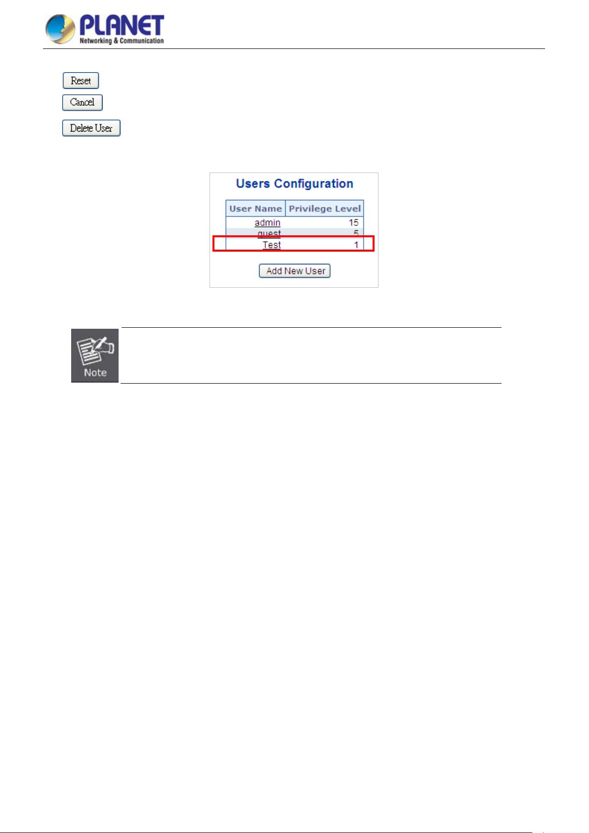
User’s Manual of GS-5220 PoE Series Managed Switch
78
he
will restore to the default
: Click to undo any changes made locally and revert to previously saved values.
: Click to undo any changes made locally and return to the Users.
: Delete the current user. This button is not available for new configurations (Add new user).
Once the new user is added, the new user entry is shown on the Users Configuration page.
Figure 4-2-1-6: User Configuration Page Screenshot
If you forget the new password after changing the default password, please press the “Reset”
button on the front panel of the Managed Switch for over 10 seconds and then release it. T
current setting including VLAN will be lost and the Managed Switch
mode.
Page 79
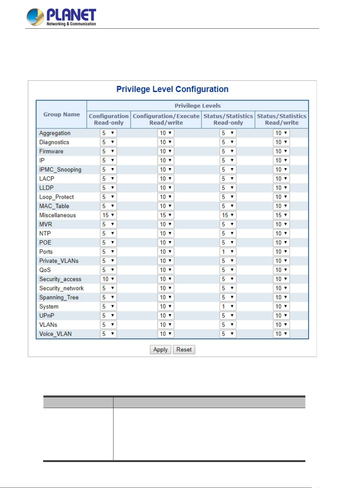
User’s Manual of GS-5220 PoE Series Managed Switch
79
4.2.1.5 Privilege Levels
This page provides an overview of the priv ilege l ev els. After setup is completed, please press the “Apply” button to tak e effect.
Please login web interface with new user name and password and the screen in Figure 4-2-1-7 appears.
Figure 4-2-1-7: Privilege Levels Configuration Page Screenshot
The page includes the following fields:
Object Description
• Group Name
The name identifying the privilege group. In most cases, a privilege level group
consists of a single module (e. g. LA CP, RSTP or QoS), but a few of them contain
more than one. The following description defines these privilege level groups in
details:
System: Contact, Name, Location, Timezone, Log.
Page 80

User’s Manual of GS-5220 PoE Series Managed Switch
80
Security: Authent i cat ion, S y st em Access Management, Port (contain s D ot 1x
port, MAC based and the MAC Address Limit), ACL, HTTPS, SSH, ARP
Inspection and IP source guard.
IP: Everything except 'ping'.
Port: Everything except 'VeriPHY'.
Diagnostics: 'ping' and 'VeriPHY'.
Maintenance: CLI- System Reboot, System Restore Default, System
Password, Configuration Save, Configuration Load and Firmware Load.
Web- Users, Privilege Levels and everything in Maintenance.
Debug: Only present in CLI.
Buttons
• Privilege Level
Every privilege level group has an authorization level for the following sub
groups:
Configuration read-only
Configuration/execute read-write
Status/statistics read-only
Status/statistics read-write (e.g. for clearing of statistics).
: Click to apply changes.
: Click to undo any changes made locally and revert to previously saved values.
Page 81

User’s Manual of GS-5220 PoE Series Managed Switch
81
4.2.1.6 NTP Configuration
Configure NTP on this page. NTP is an acronym for Network Time Protocol, a network pr otocol for synchroniz ing th e clo c ks of
computer systems. NTP uses UDP (data grams) as transport layer. You can specify NTP Servers. The NTP Configuration
screen in Figure 4-2-1-8 appears.
Figure 4-2-1-8: NTP
Configuration Page Screenshot
The page includes the following fields:
Object Description
• Mode
• Server #
Indicates the NTP mode operation. Possible modes are:
Enabled: Enable NTP mode operation. When enabling NTP mode
operation, the agent forward and transfer NTP messages between the
clients and the server when they are not on the same subnet domain.
Disabled: Disable NTP mode operation.
Provide the NTP IPv4 or IPv6 address of this switch. IPv6 address is in 128-bit
records represented as eight fields of up to four hexadecimal digits with a colon
separating each field (:).
For example, 'fe80::215:c5ff:fe03:4dc7'. The symbol '::' is a special syntax that
can be used as a shorthand way of representing multiple 16-bit groups of
contiguous zeros, but it can only appear once. It also uses a legal IPv4 address
like '::192.1.2.34'.
Buttons
: Click to apply changes.
: Click to undo any changes made locally and revert to previously saved values.
Page 82

User’s Manual of GS-5220 PoE Series Managed Switch
82
4.2.1.6.1 System Time Correction Manually
Configure NTP on this page. NTP is an acronym for Network Time Protocol, a network pr otocol for synchroniz ing th e clo c ks of
computer systems. NTP uses UDP (data grams) as transport layer. You can specify NTP Servers. The NTP Configuration
screen in Figure 4-2-1-8 appears.
Figure 4-2-1-8: System time correction Manually Page Screenshot
The page includes the following fields:
Object Description
• User Manually
• Date
Buttons
: Click to apply changes.
Indicates the NTP mode as manual operation. Possible modes are:
Enabled: Enable NTP manual mode operation. When enabling NTP user
manually mode operation, the system time will follow the date setting.
Disabled: Disable NTP user manual mode operation.
If enable the user manually , Sw itch can set the Year / Mouth / Day/ H our / M inute
/ Second in this page
: Click to undo any changes made locally and revert to previously saved values.
Page 83

User’s Manual of GS-5220 PoE Series Managed Switch
83
4.2.1.7 Time Configuration
Configure T ime Zone on this page. A Time Zone is a region that has a uniform standard time for legal, commercial, and social
purposes. It is convenient for areas in close commercial or other communication to keep the same time, so time zones tend to
follow the boundaries of countries and their subdivisions. The Time Zone Configuration screen in Figure 4-2-1-9 appears
Figure 4-2-1-9: Time Configuration Page Screenshot
The page includes the following fields:
Object Description
• Time Zone
• Acronym
• Daylight Saving Time
Lists various Time Zones worldwide. Select appropriate Time Zone from the
drop-down and click Save to set.
User can set the acronym of the time zone. This is a User configurable acronym
to identify the time zone. ( Range: Up to 16 characters )
This is used to set the clock forward or backward according to the configurations
set below for a defined Daylight Saving Time duration. Select 'Disable' to disable
the Daylight Saving Time configuration. Select 'Recurring' and configure the
Daylight Saving Time duration to repeat the configuration every year. Select
Page 84

User’s Manual of GS-5220 PoE Series Managed Switch
84
'Non-Recurring' and configure the Daylight Saving Time duration for single time
configuration. ( Default: Disabled ).
• Start Time Settings • Week - Select the starting week number.
• Day - Select the starting day.
• Month - Select the starting month.
• Hours - Select the starting hour.
• Minutes - Select the starting minute.
• End Time Settings • Week - Select the ending week number.
• Day - Select the ending day.
• Month - Select the ending month.
• Hours - Select the ending hour.
• Minutes - Select the ending minute
• Offset Settings
Buttons
: Click to apply changes.
: Click to undo any changes made locally and revert to previously saved values.
Enter the number of minutes to add during Daylight Saving Time. ( Range: 1 to
1440 )
4.2.1.8 UPnP
Configure UPnP on this page. UPnP is an acronym for Universal Plug and Play. The goals of UPnP are to allow devices to
connect seamlessly and to simplify the implementation of networks in the home (data sharing, com mun ica tion s, and
entertainment) and in corporate environments for simplified installation of computer components. The UPnP Configuration
screen in Figure 4-2-1-10 appears.
Figure 4-2-1-10: UPnP Configuration Page Screenshot
Page 85

User’s Manual of GS-5220 PoE Series Managed Switch
85
The page includes the following fields:
Object Description
• Mode
• Advertising Duration
• IP A ddressing Mode
Indicates the UPnP operation mode . Pos sible mod es are:
Enabled: Enable UPnP mode operation.
Disabled: Disable UPnP mode operation.
When the mode is enabled, two ACEs are added automatically to trap UPnP
related packets to CPU. The ACEs are automatically removed when the mode is
disabled.
The duration, carried i n SS DP packets, is used to inform a control point or contr ol
points how often it or they should receive a SSDP advertisement message from
this switch. If a control point does not receive any message within the duration, it
will think that the switch no longer exists. Due to the unreliable nature of UDP, in
the standard it is recommended that such refreshing of advertisements to be
done at less than one-half of the advertising duration. In the implementation, the
switch sends SSDP messages periodically at the interval one-half of the
advertising duration minus 30 seconds. Valid values are in the range 100 to
86400.
IP addressing mode provides two ways to determine IP address assignment:
Dynamic: Default selection for UPnP. UPnP module helps users choosing the IP
Buttons
address of the switch device. It finds the first available system IP address.
Static: User specifies the IP interface VLAN for choosing the IP address of the
switch device.
• Static VLAN Interface
ID
: Click to apply changes
: Click to undo any changes made locally and revert to previously saved values.
The index of the specific IP VLAN interface. It will only be applied when IP
Addressing Mode is static. Valid configurable values ranges from 1 to 4095.
Default value is 1.
Figure 4-2-1-11: UPnP
devices Shown on Windows My Network Place
Page 86

User’s Manual of GS-5220 PoE Series Managed Switch
86
4.2.1.9 DHCP Relay
Configure DHCP Relay on this page. DHCP Relay is used to forward and transfer DHC P m essa ges betw een the client s and th e
server when they are not on the same subnet domain.
The DHCP option 82 enables a DHCP relay agent to insert specific information into a DHCP request packets when forwarding
client DHCP pack ets to a DHCP serv er a nd remove the specific inf or ma tio n from a DHCP re ply pa ck ets w hen f orwarding server
DHCP packets to a DHCP client. The DHCP server can use this information to implement IP address or other assignment
policies. Specifically the option works by setting two sub-options:
Circuit ID (option 1)
Remote I D (option 2)
The Circuit ID sub-option is supposed to include information specific to which circuit the request came in on.
The Remote ID sub-option was designed to carry information relating to the remote host end of the circuit.
The definition of Circuit ID in the switch is 4 bytes in length and the format is "vlan_id" "module_id" "port_no". The parameter of
"vlan_id" is the first two bytes representing the VLAN ID. The parameter of "module_id" is the third byte for the module ID. T he
parameter of "port_no" is the fourth byte and it means the port number.
The Remote ID is 6 bytes in length, and the value equals the DHC P relay ag ent’ s M AC addr ess. The DHCP Relay Configuration
screen in Figure 4-2-1-12 appears.
Figure 4-2-1-12 DHCP Relay Configuration Page Screenshot
The page includes the following fields:
Object Description
• Relay Mode
Indicates the DHCP relay mode operation. Possible modes are:
Enabled: Enable DHCP relay mode operation. When enabling DHCP relay
mode operation, the agent forwards and transfers DHCP me ssa ges betw een
the clients and the server when they are not on the same subnet domain.
And the DHCP broadcast message won't flood for security considered.
Disabled: Disable DHCP relay mode operation.
• Relay Server
• Relay Information
Indicates the DHCP relay server IP address. A DHCP relay agent is used to
forward and transfer DHCP messages between the clients and the server when
they are not on the same subnet domain.
Indicates the DHCP relay information mode option operation. Possible modes
Page 87

User’s Manual of GS-5220 PoE Series Managed Switch
87
contains relay age nt information. It will enforce the policy. And it only works under
Mode are:
Enabled: Enable DHCP relay information mode operation. When enabling
DHCP relay information mode operation, the agent inserts specific
information (option82) into a DHCP message when forwarding to DHCP
server and removing it from a DHCP message when transferring to DHCP
client. It only works under DHCP relay operation mode enabled.
Disabled: Disable DHCP relay information mode operation.
Buttons
• Relay Information
Policy
Indicates the DHCP relay information option policy. When enabling DHCP relay
information mode operation, if agent rec eiv es a DHCP message that already
DHCP relay information operation mode enabled. Possible policies are:
Replace: Replace the original relay information when receiving a DHCP
message that already contains it.
Keep: Keep the original relay information when receiving a DHCP message
that already contains it.
Drop: Drop the package when receiving a DHCP message that already
contains relay information.
: Click to apply changes
: Click to undo any changes made locally and revert to previously saved values.
4.2.1.10 DHCP Relay Statistics
This page provides statistics for DHCP relay. The DHCP Relay Statistics screen in Figure 4-2-1-13 appears.
Figure 4-2-1-13: DHCP Relay Statistics Page Screenshot
Page 88

User’s Manual of GS-5220 PoE Series Managed Switch
88
The page includes the following fields:
Server Statistics
Object Description
• Transmit to Server
• Transmit Error
• Receive from Server
• Receive Missing Agent
Option
• Receive Missing
Circuit ID
• Receive Missing
Remote ID
• Receive Bad Circuit ID
Receive Bad Remote ID The packet number whose the Remote ID option did not match the known
Client Statistics
The packet number that relayed from client to server.
The packet number that erroneously sent packets to client s .
The packet number that received packets from server.
The packet number that received packets without agent information options.
The packet number that received packets whose the Circuit ID option was
missing.
The packet number that received packets whose Remote ID option was missing.
The packet number whose the Circuit ID option did not match the known circuit
ID.
Remote ID.
Object Description
• Transmit to Client
• Transmit Error
• Receive from Client
• Receive A gent Option
• Replace Agent Option
• Keep Agent Option
• Drop Agent Option
Buttons
Auto-refresh : Check this box to refresh the page automatically. Automatic refresh occurs every 3 seconds.
The packet number that relayed packets from server to client.
The packet number that erroneously sent packets to server s .
The packet number that received packets from server.
The packet number that received packets with relay agent information option.
The packet number that replaced received packets with relay agent information
option.
The packet number that kept received packets with relay agent information
option.
The packet number that dropped received packets with relay agent information
option.
: Click to refresh the page immediately.
: Clears all statist ics.
Page 89

User’s Manual of GS-5220 PoE Series Managed Switch
89
, please download Adobe SVG tool and
4.2.1.11 CPU Load
This page displays the CPU load, using an SVG graph. The load is measured as average over the last 100ms, 1 sec and 10
seconds intervals. The last 120 samples are gr aph ed, and the last numbers are d is play ed a s text as well. In order to display the
SVG graph, your browser must support the SVG format. Consult the SVG Wiki for more information on browser support.
Specifically, at the time of writing, Microsoft Internet E x plorer w ill need to have a pl ugin in stalled t o sup port SVG . The CPU Load
screen in Figure 4-2-1-14 appears.
Figure 4-2-1-14: CPU Load Page Screenshot
Buttons
Auto-refresh : Check this box to refresh the page automatically. Automatic refresh occurs every 3 seconds.
If your browser cannot display anything on this page
install it in your computer.
Page 90

User’s Manual of GS-5220 PoE Series Managed Switch
90
4.2.1.12 System Log
The Managed Switch system log information is provided here. The System Log screen in Figure 4-2-1-15 appears.
Figure 4-2-1-15: System Log Page Screenshot
The page includes the following fields:
Object Description
• ID
• Level
• Clear Level
• Time
• Message
The ID (>= 1) of the system log entry.
The level of the system log entry. The following level types are supported:
Info: Information level of the system log.
Warning: Warning level of the system log.
Error: Error level of the system log.
All: All levels.
To clear the system log entry level. T he following level types are supported:
Info: Information level of the system log.
Warning: Warning level of the system log.
Error: Error level of the system log.
All: All levels.
The time of the system log entry.
The message of the system log entry.
Buttons
Auto-refresh : Check this box to refresh the page automatically. Automatic refresh occurs every 3 seconds.
: Updates the system log entries, starting from the current entry ID.
: Flushes the selected log entries.
: Hides the selected log entries.
: Downloads the selected log entries.
Page 91

User’s Manual of GS-5220 PoE Series Managed Switch
91
: Updates the system log entries, starting from the first available entry ID.
: Updates the system log entries, ending at the last entry currently displayed.
: Updates the system log entries, starting from the last entry currently displayed.
: Updates the system log entries, ending at the last available entry ID.
4.2.1.13 Detailed Log
The Managed Switch system detailed log information is provided here. The Detailed Log screen in Figure 4-2-1-16 appears.
The page includes the following fields:
Object Description
• ID
• Message
Buttons
: Download the system log entry to the current entry ID.
: Updates the system log entry to the current entry ID.
: Updates the system log entry to the first available entry ID.
: Updates the system log entry to the previous available entry ID.
: Updates the system log entry to the next available entry ID.
Figure 4-2-1-15: Detailed Log Page Screenshot
The ID (>= 1) of the system log entry.
The message of the system log entry.
: Updates the system log entry to the last available entry ID.
: Print the system log entry to the current entry ID.
Page 92

User’s Manual of GS-5220 PoE Series Managed Switch
92
4.2.1.14 Remote Syslog
Configure remote syslog on this page. The Remote Syslog screen in Figure 4-2-1-17 appears.
Figure 4-2-1-17: Remote Syslog Page Screenshot
The page includes the following fields:
Object Description
Buttons
• Mode
• Syslog Server IP
• Syslog Level
Indicates the server mode operation. When the mode operation is enabled, the
syslog message will send out to syslog server. The syslog protocol is based on
UDP communication and r ecei ved on UD P por t 514 and the s yslog server will not
send acknowledgments back sender since UDP is a connectionless protocol and
it does not provide acknowledgments. The syslog packet will always send out
even if the syslog server does not exist. Possible modes are:
Enabled: Enable remote syslog mode operation.
Disabled: Disable remote syslog m ode operation.
Indicates the IPv4 host address of syslog server. If the switch provides DNS
feature, it also can be a host name.
Indicates what kind of message will send to syslog server. Possible modes are:
Info: Send information, warnings and errors.
Warning: Send warnings and errors.
Error: Send errors.
: Click to apply changes
: Click to undo any changes made locally and revert to previously saved values.
Page 93
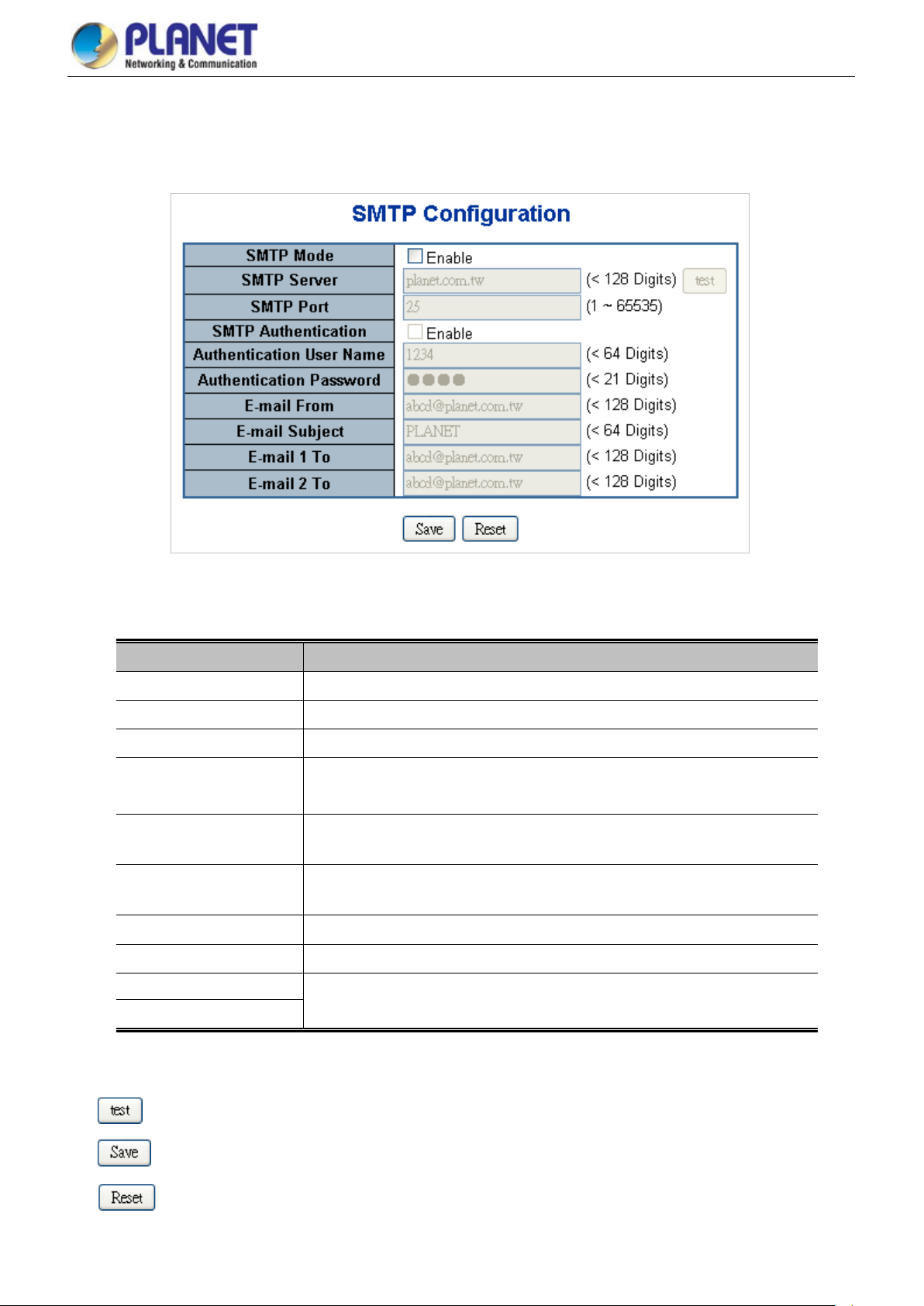
User’s Manual of GS-5220 PoE Series Managed Switch
93
4.2.1.15 SMTP Configuration
This page facilitates an SMTP Configuration on the switch. The SMTP Configure screen in Figure 4-2-1-18 appears.
Figure 4-2-1-18: SMTP Configuration Page Screenshot
The page includes the following fields:
Object Description
• SMTP Mode
• SMTP Server
• SMTP Port
• SMTP A uthentication
• Authentication User
Name
• Authentication
Password
• E-mail From
• E-mail Subject
• E-mail 1 To
Controls whether SMTP is enabled on this switch.
Type the SMTP server name or the IP address of the SMTP server.
Set port number of SMTP service.
Controls whether SMTP authentication is enabled if authentication is required
when an e-mail is sent.
Type the user name for the SMTP server if Authentication is Enabled.
Type the password for the SMTP server if Authentication is Enabled.
Type the sender’s e-mail address. This address is used for reply e-mails.
Type the subject/title of the e-mail.
Type the receiver’s e-mail address.
• E-mail 2 To
Buttons
: Send a test mail to mail server to check whether this account is available or not.
: Click to save changes.
: Click to undo any changes made locally and revert to previously saved values.
Page 94

User’s Manual of GS-5220 PoE Series Managed Switch
94
4.2.2 Simple Network Management Protocol
4.2.2.1 SNMP Overview
The Simple Network Management Protocol (SNMP) is an application layer protocol that facilitates the exchange of
management information between network devices. It is part of the Transmission Control Protocol/Internet Protocol (TCP/IP)
protocol suite. SNMP enables network administrators to manage network performance, find and solve network problems, and
plan for network growth.
An SNMP-managed network consists of three key components: Network management stations (NMSs), SNMP agents,
Management information base (MIB) and network-management protocol:
■ Network management stations (NMSs): Sometimes called consoles, these devices execute management applications
that monitor and control network elements. Physically, NMSs are usually engineering workstation-caliber computers with
fast CPUs, megapix el color di s play s, sub sta ntia l m emory, and abundant disk space . At least one NMS must be present in
each managed environment.
■ Agents: Agents are software modules that reside in network elements. They collect and store management information
such as the number of error packets received by a network element.
■ Management information base (MIB): A MIB is a collection of managed objects residing in a virtual information store.
Collections of related managed objects are defined in specific MIB modules.
■ Network-management protocol: A management protocol is used to convey management information between agents
and NMSs. SNMP is the Internet community's de facto standard management protocol.
Figure 4-2-2-1:
SNMP Operations
SNMP itself is a simple request/response protocol. NMSs can send multiple requests without receiving a response.
■ Get -- Allows the NMS to retrieve an object instance from the agent.
■ Set -- Allows the NMS to set values for object instances within an agent.
■ Trap -- Used by the agent to asynchronously inform the NMS of some event. The SNMPv2 trap message is designed to
replace the SNMPv1 trap message.
Page 95

User’s Manual of GS-5220 PoE Series Managed Switch
95
SNMP Community
An SNMP community is the group that devices and management stations running SNMP belong to. It helps define where
information is sent. The community name is used to identify the group. An SNMP device or agent may belong to more than one
SNMP community. It will not respond to requests from management stations that do not belong to one of its communities.
SNMP default communities are:
。 Write = private
。 Read = public
Use the SNMP Menu to display or configure the Managed Switch's SNMP function. This section has the following items:
System Configuration Configure SNMP on this page.
Trap Configuration Configure SNMP trap on this page.
System Information The system information is provided here.
SNMPv3 Communities Configure SNMPv3 communities table on this page.
SNMPv3 Users Configure SNMPv3 users table on this page.
SNMPv3 Groups Configure SNMPv3 groups table o n this page.
SNMPv3 Views Configure SNMPv3 views table on this page.
SNMPv3 Access Configure SNMPv3 accesses table on this page.
4.2.2.2 SNMP System Configuration
Configure SNMP on this page. The SNMP System Configuration screen in Figure 4-2-2-2 appears.
Figure 4-2-2-2: SNMP System Configuration Page Screenshot
The page includes the following fields:
Object Description
• Mode
Indicates the SNMP mode operation. Possible modes are:
Enabled: Enable SNMP mode operation.
Disabled: Disable SNMP mode operation.
• Version
Indicates the SNMP supported version. Possible versions are:
Page 96

User’s Manual of GS-5220 PoE Series Managed Switch
96
SNMP v1: Set SNMP supported version 1.
SNMP v2c: Set SNMP supported version 2c.
SNMP v3: Set SNMP supported version 3.
• Read Community
• Write Community
Indicates the community read access string to permit access to SNMP agent.
The allowed string length is 0 to 255, and the allowed content is the ASCII
characters from 33 to 126.
The field is applicable only when SNMP version is SNMPv1 or SNMPv2c. If
SNMP version is SNMPv3, the community string will be associated with SN MPv3
communities table. It provides more flexibility to configure security name than a
SNMPv1 or SNMPv2c community string. In addition to community string, a
particular range of source addresses can be used to restrict source subnet.
Indicates the community write access string to permit access to SNMP agent.
The allowed string length is 0 to 255, and the allowed content is the ASCII
characters from 33 to 126.
The field is applicable only when SNMP version is SNMPv1 or SNMPv2c. If
SNMP version is SNMPv3, the community string will be associated with SN MPv3
communities table. It provides more flexibility to configure security name than a
SNMPv1 or SNMPv2c community string. In addition to community string, a
Buttons
particular range of source addresses can be used to restrict source subnet.
• Engine ID
: Click to apply changes
: Click to undo any changes made locally and revert to previously saved values.
Indicates the SNMPv3 engine ID. The string must contain an even number
between 10 and 64 hexadecimal digits, but all-zeros and all-'F's are not allowed.
Change of the Engine ID will clear all original local users.
Page 97

User’s Manual of GS-5220 PoE Series Managed Switch
97
4.2.2.3 SNMP Trap Configuration
Configure SNMP trap on this page. The SN MP Tr ap Configur ation screen in Figure 4-2-2-3 appears.
Figure 4-2-2-3: SNMP Trap Configuration Page Screenshot
The page includes the following fields:
Object Description
• Trap Config
• Trap Mode
Indicates which trap Configuration's name for configuring. The allowed string length
is 0 to 255, and the allowed content is ASCII characters from 33 to 126.
Indicates the SNMP trap mode operation. Possible modes are:
Enabled: Enable SNMP trap mode operation.
Disabled: Disable SNMP trap mode operation.
• Trap Version
Indicates the SNMP trap supported version. Possible versions are:
SNMP v1: Set SNMP trap supported version 1.
Page 98

User’s Manual of GS-5220 PoE Series Managed Switch
98
SNMP v2c: Set SNMP trap supported version 2c.
SNMP v3: Set SNMP trap supported version 3.
• Trap Community
• Trap Destination
Address
• Trap Destination Port
• Trap Inform Mode
• Trap Inform Timeout
(seconds)
• Trap Inform Retry
Times
• Trap Probe Security
Engine ID
Indicates the community access string when send SNMP trap packet. The allowed
string length is 0 to 255, and the allowed content is the ASCII characters from 33 to
126.
Indicates the SNMP trap destination address.
Indicates the SNMP trap destination p ort. SNMP Agent will send SNMP message via
this port, the port range is 1~65535.
Indicates the SNMP trap inform mode operation. Possible modes are:
Enabled: Enable SNMP trap authentication failure.
Disabled: Disable SNMP trap authentication failure.
Indicates the SNMP trap inform timeout.
The allowed range is 0 to 2147.
Indicates the SNMP trap inform retry times.
The allowed range is 0 to 255.
Indicates the SNMPv3 trap probe security engine ID mode of operation. Possible
values are:
• Trap Security Engine
ID
• Trap Security Name
• System
• Interface
Enabled: Enable SNMP trap probe security engine ID mode of operation.
Disabled: Disable SNMP trap probe security engine ID mode of operation.
Indicates the SNMP trap security engine ID. SNMPv3 sends traps and informs using
USM for authentication and privacy. A unique engine ID for these traps and informs
is needed. When "Trap Probe Security Engine ID" is enabled, the ID will be probed
automatically. Otherwise, the ID specified in this field is used. The string must
contain an even number(in hexadecimal format) with number of digits between 10
and 64, but all-zeros and all-'F's are not allowed.
Indicates the SNMP trap security name. SNMPv3 traps and informs using USM for
authentication and privacy. A unique security name is needed when traps and
informs are enabled.
Enable/disable that the Interface group's traps. Possible traps are:
Warm Start: Enable/disable Warm Start trap.
Cold Start: Enable/disable Cold Start trap.
Indicates that the Interface group's traps. Possible traps are:
Link Up: Enable/disable Link up trap.
Link Down: Enable/disable Link down trap.
LLDP: Enable/disable LLDP trap.
• AAA
• Switch
Indicates that the AAA group's traps. Possible traps are:
Authentication Fail : Enable/disable SNMP trap authentication failure trap.
Indicates that the Switch group's traps. Possible traps are:
Page 99

User’s Manual of GS-5220 PoE Series Managed Switch
99
STP: Enable/disable STP trap.
RMON: Enable/disable RMON trap.
Buttons
: Click to apply changes
: Click to undo any changes made locally and revert to previously saved values.
4.2.2.4 SNMP System Information
The switch system information is provided here. The SNMP System Information screen in Figure 4-2-2-4 appears.
Figure 4-2-2-4: System Information Confi gur at ion Page Screenshot
The page includes the following fields:
Object Description
• System Contact
• System Name
• System Location
The textual identification of the contact person for this managed node, together
with information on how to contact this person. The allowed string length is 0 to
255, and the allowed content is the ASCII characters from 32 to 126.
An administratively assigned name for this managed node. By convention, this is
the node's fully-qualified domain name. A domain name is a text string drawn
from the alphabet (A-Z, a-z), digits (0-9), minus sign (-). No space characters are
permitted as part of a name. The first character must be an alpha character. And
the first or last character must not be a minus sign. The allowed str ing len gth is 0
to 255.
The physical location of this node (e.g., telephone closet, 3rd floor). The allow ed
string length is 0 to 255, and the allowed content is the ASCII characters from 32
to 126.
Page 100
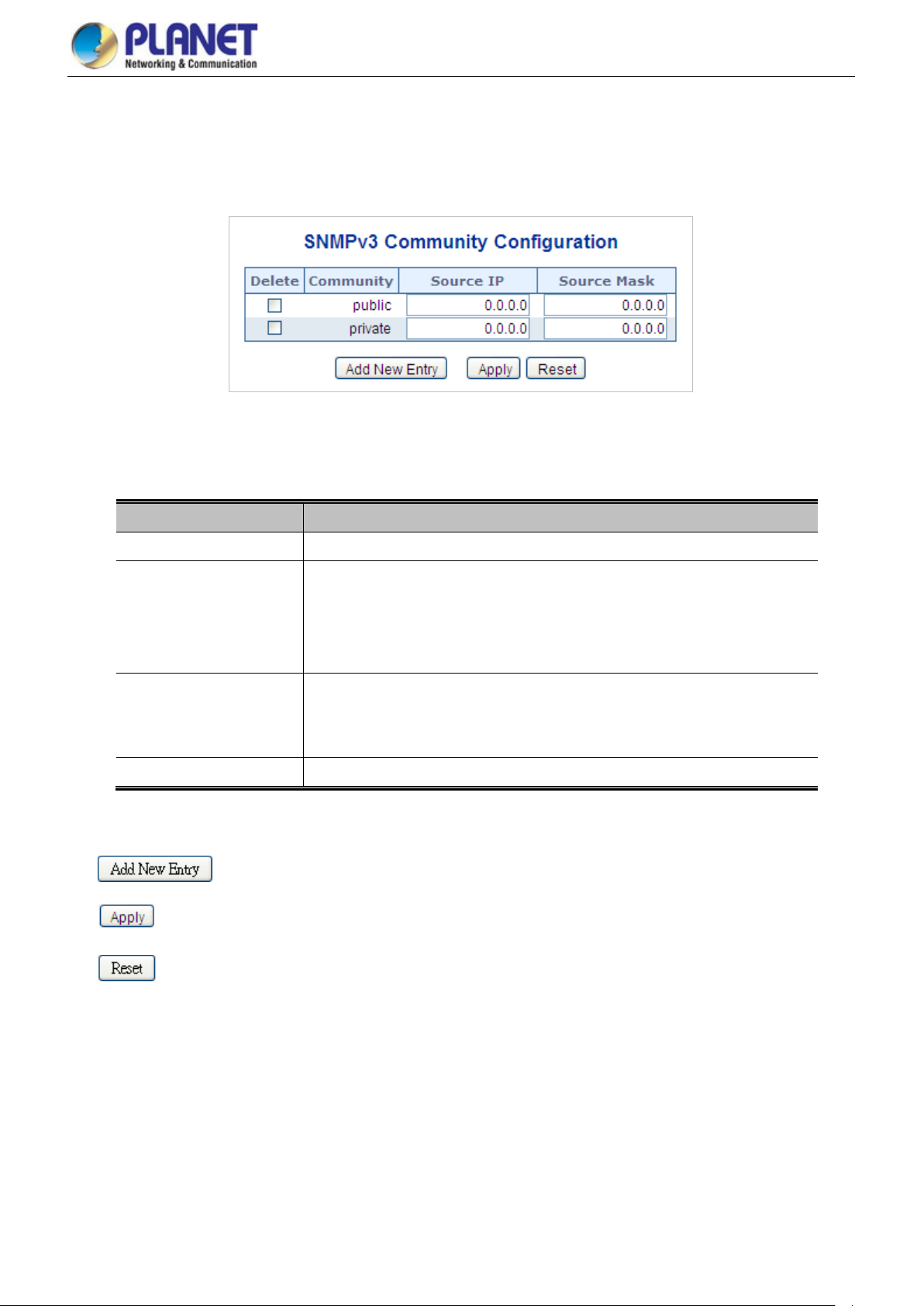
User’s Manual of GS-5220 PoE Series Managed Switch
100
4.2.2.5 SNMPv3 Communities
Configure SNMPv3 communities table on this page. The entry index key is Community. The SNMPv3 Communities screen in
Figure 4-2-2-5 appears.
Figure 4-2-2-5: SNMPv3 Communities Configuration Page Screenshot
The page includes the following fields:
Buttons
Object Description
• Delete
• Community
• Source IP
• Source Mask
: Click to add a new community entry.
: Click to apply changes
Check to delete the entry. It will be deleted during the next save.
Indicates the community access string to permit access to SNMPv3 agent. The
allowed string length is 1 to 32, and the allowed content is ASCII characters from
33 to 126. The community string will be treated as security name and map a
SNMPv1 or SNMPv2c community string.
Indicates the SNMP access source address. A particular range of source
addresses can be used to restrict source subnet when combined with sour c e
mask.
Indicates the SNMP access source address mask.
: Click to undo any changes made locally and revert to previously saved values.
 Loading...