

Page 1

Copyright
Copyright © PLANET Technology Corp. 2004.
Contents subject to revision without prior notice.
PLANET is a registered trademark of PLANET Technology Corp. The information in this manual is subject to
change without notice. All other trademarks belong to
their respective owners.
Disclaimer
PLANET Technology does not warrant that the hardware
will work properly in all environments and applications,
and makes no warranty and representation, either
implied or expressed, with respect to the quality, performance, merchantability, or tness for a particular
purpose.
PLANET has made every effort to ensure that this User‘s
Manual is accurate; PLANET disclaims liability for any
inaccuracies or omissions that may have occurred.
Information in this User’s Manual is subject to change
without notice and does not represent a commitment on
the part of PLANET. PLANET assumes no responsibility
for any inaccuracies that may be contained in this User‘s
Manual. PLANET makes no commitment to update or
keep current the information in this User’s Manual, and
reserves the right to make improvements to this User‘s
Manual and/or to the products described in this User’s
Manual, at any time without notice. If you nd information in this manual that is incorrect, misleading, or
incomplete, we would appreciate your comments and
suggestions.
FCC Warning
This equipment has been tested and found to comply
with the regulations for a Class A digital device, pursuant to Part 15 of the FCC Rules. These limits are
designed to provide reasonable protection against
harmful interference when the equipment is operated in
a commercial environment. This equipment generates,
uses, and can radiate radio frequency energy and, if not
installed and used in accordance with this user’s guide,
Page 2

may cause harmful interference to radio communications. Operation of this equipment in a residential area
is likely to cause harmful interference, in which case the
user will be required to correct the interference at his
own expense.
CE Mark Warning
This is a Class A product. In a domestic environment,
this product may cause radio interference, in which case
the user may be required to take adequate measures.
Revision
User’s manual for PLANET Fast Ethernet Converter
Multi-mode: FT-701B, FT-702B, FT-703, FT-704
Single-mode: FT-702S15, FT-702S35, FT-702S50,
FT-703S, FT-706A15, FT-706B15
Rev 4.0 (July 2004)
Part No. 2010-000001-003
Page 3

Table of Contents
Chapter 1 Overview 1
Chapter 2 Model List 1
Chapter 3 Checklist 2
Chapter 4 Product Outlook 2
Chapter 5 Installing the Converter 3
Chapter 6 Duplex Mode Setting 5
Chapter 7 The LED Indications 6
Chapter 8 Cable Connection Parameter 7
Chapter 9 Technical Specifications 8
Chapter 10 Power information 9
Page 4

1
Chapter 1
Overview
Thank you for purchasing PLANET FT-70X family Fast Ethernet
Twisted pair to Fiber-optic Converter. This converter is used to
convert one type media signal to other type equivalent that allows
two type segments connect easily, efciently and inexpensively.
This converter can be used as a standalone unit or as a slide-in
module to the 10 /19 media chassis (up to 15 units) for a TP
and Fiber combined networks at a central wiring closet. Please
contact with your sales representative for more about the 19
media chassis.
Chapter 2
Model List
Your Fast Ethernet Converter comes with one of the following
models.
ð FT-701B on board ST fiber connector
ð FT-702B/S on board SC fiber connector
ð FT-703/S on board MT-RJ fiber connector
ð FT-704/S on board VF-45 fiber connector
ð FT-706A15 on board single SC fiber connector
ð FT-706B15 on board single SC fiber connector
Models with last two numbered characters indicates the berport is with Single-Mode optic ber connector and the number
indicates the maximum distance in km. The rest will be MultiMode optic ber models.
In the following sections, the term FT-70X indicates the product
family above.
Page 5
2
3
Chapter 3
Checklist
Your FT-70X carton should contain the following items:
ð The Fast Ethernet Converter
ð AC-DC Power Adapter (Output: 5VDC, 2 A max.)
ð This user’s manual
If any item is missing or damaged, please consult the dealer from
whom you purchased your Fast Ethernet Converter.
Chapter 4
Product Outlook
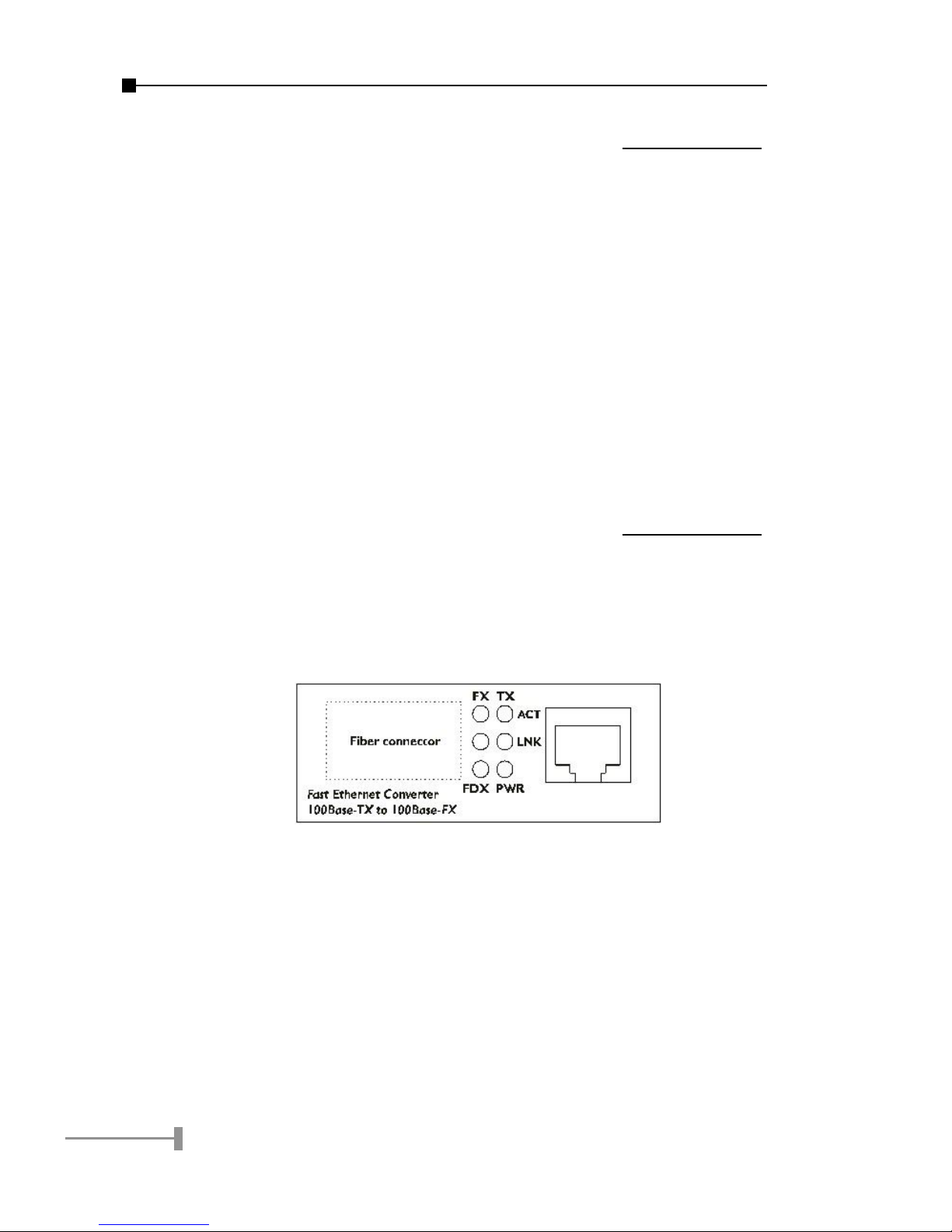
Right View (FT-70X)
There are one RJ-45 Twisted-Pair jack, one ber-optic connector
and six LED indicators on this side.
The ber connector is different from model to model. Please refer
to the section 2 Model List and section 9 Technical Specication
for detail.
Page 6

3
Left View (FT-70X)
One DC jack for DC power input.
Side View (FT-70X)
One DIP Switch for TP Device selection.
Chapter 5
Installing the Converter
Please follow these steps to install the converter:
• Turn off the power of the device/station in a network to
which the FT-70X will be attached.
• Ensure that there is no activity in the network.
• Attach fiber cable from the FT-70X to the fiber network.
TX, RX must be paired at both ends for some two con-
nectors models.
• Attach a Cat. 5 UTP cable from the 100Base-TX network
to the RJ-45 port on the FT-70X.
Page 7

4
5
• Connect the 5VDC power adapter to the FT-70X and
verify that the Power LED lights up.
• Turn on the power of the device/station, the TX Link and
FX Link LEDs should light when all cables are attached.
NOTE:
• RJ-45/STP, UTP Cat 5, straight-through
cable is accepted.
• Cabling from FT-70X TP port to a TP de-
vice is as below:
• To Workstation: DIP switch on DTE
• To Hub/Switch: DIP switch on MPR
• Please refer to section 8 for more about
the wiring distance of your TP, Optic-fiber
networks.
• Please note FT-706A15/706B15 is de-
signed to work together. It means you
must connect FT-706A15 to FT-706B15
from them to work normally. If both ends
are FT-706A15 or FT-706B15, they can’t
work normally and may damage the fiber
connectors.
Page 8

5
Chapter 6
Duplex Mode Setting
The twisted pair port of FT-70X support duplex mode selection
by Auto-Negotiation (A-N). The following is the duplex mode
parameters:
Fast Ethernet Device FT-70X Duplex Mode support
Fast Ethernet Hub Half-Duplex
Fast Ethernet Switch
(without A-N)
Half-Duplex
Fast Ethernet Devices *
Support Auto-Negotiation
Full-Duplex / Half-Duplex
NOTE:
Normally, an A-N switch will be detected and
set to Full-duplex where a dual-speed hub
will be detected and set to Half-Duplex.
Page 9

6
7
Chapter 7
The LED Indications
LED Color Status Description
TP ACT Green
Blinks
If fiber-optic is not present
for converter self-diagnose /
detecting
Blinks
If both ports link with any TP
packets transmitting
OFF Fiber-optic link is present
OFF
With no TP/FX LINK on, i.e.
only turn on the power and
the ACT do not blink at all,
please consult your local
dealer
TP Link Green ON TP connection is good
FX ACT Green Blinks
When any FX packets
transmitting
FX Link Green ON
When Fiber connection is
good
FDX* Green ON
When Full-duplex mode is
detected in TP port
PWR Green ON
When +5VDC power
detected
NOTE:
Fiber-optic partner should be set to the correct
mode according to this FDX indicator for optimal
network performance.
Page 10

7
Chapter 8
Cable Connection Parameter
The cable distance limitations are as below:
Duplex Connection Limitation (max.)
Twisted Pair
Half / Full
Node to Node
Node to Switch/Hub
100 meters
Multi-Mode Converters
MM Half*
Node to Node
Node to Switch
412 meters
MM Full
Node to Node
Node to Switch
2 kilometers
Single-Mode Converters (FT-70xS, FT-706A15/706B15)
SM Full
Node to Node
Node to Switch
FT-70xS15: 15 km
FT-70xS35: 35 km
FT-70xS50: 50 km
FT-706A15: 15 km
FT-706B15: 15 km
NOTE:
If the ber port works on half duplex, please
note that Fast Ethernet/100Base-TX network
allows 512 bit-time delay between any two
nodes/stations in a collision domain (when work
in half duplex). The overall bit time of TP/Fiber
wires and devices must below 512 bit-time in
one network segment. To extend the distance,
however, you may use switch to break up a
collision domain and extend the distance.
Page 11

8
9
Chapter 9
Technical Specifications
The FT-70X comes with the following features:
Standard
IEEE 802.3u, 100Base-TX and
100Base-FX
TP Connector
One RJ-45 Twisted Pair, EIA568
connectors
Fiber Connector
FT-701B: ST
FT-702B: SC
FT-702S series: SC
FT-703 series: MT-RJ
FT-704 series: VF-45
FT-706A/FT-706B series: single SC
Optical
wavelength
FT-706A15: Tx-1310nm, Rx-1550nm
FT-706B15: Tx-1550nm, Rx-1310nm
Others: Tx and Rx -1310nm
Data Rate 100Mbps
Duplex mode
Full or half-duplex mode by Auto-
Negotiation
LED indicators PWR, TX LNK/ACT, FX LNK/ACT, FDX
Power
Requirement
5V ,2A
Ambient
Temperature
0° to 50°C
Humidity 5% to 90%
Dimension 26 x 70 x 97mm (HxWxD)
Page 12
9
Cable
• UTP : Cat 5 UTP cable
• Fiber-MM: 50/125 μm or 62.5/
125 μm optic fiber
• Fiber-SM: 8.3/125, 8.7/125, 9/
125 μm optic fiber
Chapter 10
Power information
The power jack of FT-70X is with 2.5mm in the central post and
required +5VDC / 2A power input. It will conform to the bundled
AC-DC adapter and PLANET s Media Chassis. Should you have the
problem to make the power connection, please contact your local
sales representative.
Please keep the AC-DC adapter as spare parts when your FT-70X
is installed to a Media Chassis.
Page 13

10
This page is intentionally left blank
Page 14

Page 15

2010-000001-003
 Loading...