

Page 1

Trademarks
Copyright PLANET Technology Corp. 2007.
Contents subject to which revision without prior notice.
PLANET is a registered trademark of PLANET Technology
Corp. All other trademarks belong to their respective
owners.
Disclaimer
PLANET Technology does not warrant that the hardware
will work properly in all environments and applications,
and makes no warranty and representation, either implied
or expressed, with respect to the quality, performance,
merchantability, or fitness for a particular purpose.
PLANET has made every effort to ensure that this User’s
Manual is accurate; PLANET disclaims liability for any
inaccuracies or omissions that may have occurred.
Information in this User’s Manual is subject to change
without notice and does not represent a commitment on
the part of PLANET. PLANET assumes no responsibility
for any inaccuracies that may be contained in this User’s
Manual. PLANET makes no commitment to update or
keep current the information in this User’s Manual, and
reserves the right to make improvements to this User’s
Manual and/or to the products described in this User’s
Manual, at any time without notice.
If you find information in this manual that is incorrect,
misleading, or incomplete, we would appreciate your
comments and suggestions.
Page 2

FCC Warning
This equipment has been tested and found to comply with
the limits for a Class B digital device, pursuant to Part 15
of the FCC Rules. These limits are designed to provide
reasonable protection against harmful interference when
the equipment is operated in a commercial environment.
This equipment generates, uses, and can radiate radio
frequency energy and, if not installed and used in
accordance with the Instruction manual, may cause
harmful interference to radio communications. Operation
of this equipment in a residential area is likely to cause
harmful interference in which case the user will be required
to correct the interference at whose own expense.
CE Mark Warning
This is a Class B product. In a domestic environment,
this product may cause radio interference, in which case
the user may be required to take adequate measures.
WEEE Warning
To avoid the potential effects on the environment
and human health as a result of the presence of
hazardous substances in electrical and electronic
equipment, end users of electrical and electronic
equipment should understand the meaning of the
crossed-out wheeled bin symbol. Do not dispose
of WEEE as unsorted municipal waste and have to
collect such WEEE separately.
Revision
PLANET Fast Ethernet Redundant Media Converter
User’s Manual
FOR MODELS: FT-1105A / FT-1205A
REVISION: 1.0 (MARCH.2007)
Part No.: 2010-AA3520-000
Page 3

Table of Contents
CHAPTER 1 OVERVIEW 1
CHAPTER 2 PRODUCT FEATURES 3
CHAPTER 3 CHECKLIST 5
CHAPTER 4 PRODUCT OUTLOOK 6
CHAPTER 5 DIP SWITCH 8
CHAPTER 6 INSTALLING THE CONVERTER 10
CHAPTER 7 REDUNDANCY 14
CHAPTER 8 LOOP BACK REPLY 16
CHAPTER 9 LED INDICATORS 17
CHAPTER 10 PRODUCT SPECIFICATION 20
APPENDIX A 21
Page 4

1
Chapter 1
OVERVIEW
Thank you for choosing the Smart 10/100Base-TX to 100Base-FX
Media Converter, The Media Converter introduced here provides
one channel media conversion between 10/100Base-TX and
100Base-FX.
About the Redundant Media Converter
The FT-1105A and FT-1205A are 3-Port Redundant Media
Converters which support conversion between 10/100Base-TX and
100Base-FX network. Different with the other one-port channel
media converter, the Redundant Media Converters are designed
for critical networks that require fiber or copper link auto recover
less then 10ms, such as ISP, telecom, hospital, banking and
enterprise. The two models of PLANET Redundant Media converter
as following:
FT-1105A: 100Base-FX to two 10/100Base-TX copper
link redundancy
FT-1205A: 10/100Base-TX copper to two 100Base-FX
fiber link redundancy
Via the build-in DIP-switches, the two models can be configured
as 3-Port Ethernet switch or 2-Port Redundant media converter.
With the 3-Port Switch mode, they work in high performance
Store and Forward mechanism, also can prevent packet loss with
IEEE 802.3x Flow Control (Full-Duplex) and Back Pressure (HalfDuplex).
With 2-Port redundant Mode, it provides less than 10ms link
redundancy for highly critical Ethernet applications. The redundantmode supports auto-recover function. If the destination port of a
packet is link down, it forwards the packet to the other port of
the backup pair.
Page 5

2
The Redundant Media Converters - FT-1105A and FT-1205A,
support conversion between 10/100Base-TX and 100Base-FX
network. The SFP slot supports single-mode, multi-mode and WDM
small-form factory type transceiver modules for your needs. With
100Base-FX SFP ports, the FT-1105A and FT-1205A are with high
reliability and flexibility to extend the distance up to 2km, 20km, or
longer. It depends on the 100Base-FX SFP transceiver modules.
Ethernet signal that allows two type segments connect easily,
efficiently and inexpensively.
The converters can be used as a stand-alone unit or as a slide-in
module to the PLANET Media Converter Chassis (
MC-700, MC-
1000R and MC-1500). As the other PLAENT FT-Series media
converters, they’re hot swappable in MC-Chassis.
Chapter 2
PRODUCT FEATURES
Standard
• Complies with IEEE 802.3, IEEE 802.3u 10/100Base-TX,
100Base-FX
• IEEE 802.3x Full-Duplex Flow-Control, Back-Pressure in
Half-Duplex eliminate packets loss
Interface
• FT-1105A : Dual 10/100Base-TX Copper, One 100Base-
FX SFP Fiber optic
• FT-1205A : Dual 100Base-FX SFP Fiber optic, One
10/100Base-TX Copper
• Auto-Negotiation for 100Base-TX Half-Duplex or
100Base-Full-Duplex
• Supports Auto MDI/MDI-X function
• Supports Maximum frame size up to 2046Kbytes.
Page 6

3
Redundancy
• Link status auto detect and redundant on Dual ports with
same connector type.
• Only Primary-Port is active at a time, the Backup-Port is
blocked.
• While Primary-Port link fail occur, the traffic swap to
Backup-Port automatically.
• Once the Primary-Port status back to link up, the traffic
swap from Backup-Port to Primary-Port.
• Hardware redundant swap less then 10 ms.
Mechanical
• External 5V/2A DC power supply
• LED indicators for easy network diagnose
• DIP Switch for 3-Port operation with Fast Ethernet Switch
mode or Redundant mode
• DIP switch for LBR (Loop Back Reply) on / off selection
• Compact size, easy installation
• Co-work with PLANET MC family Media Chassis
( MC-700 / 1000R / 1500
)
Page 7
4
Chapter 3
CHECKLIST
Your FT-1105A / FT-1205A carton should contain the following items:
The Redundant Fast Ethernet Converter
AC-DC Power Adapter (Output: 5VDC, 2A max.)
This user’s manual
If any item is missing or damaged, please consult the dealer from
whom you purchased your Redundant Fast Ethernet Converter.
Notice:
FT-1105A / FT-1205A is with one vacant SFP
module slot. The 100Base-FX SFP module is not
bundled with in the package
Chapter 4
PRODUCT OUTLOOK
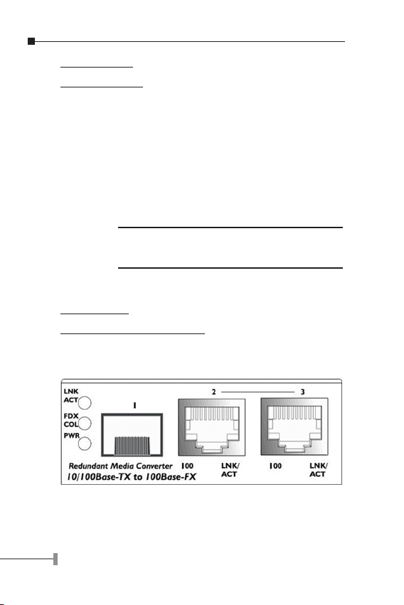
FT-1105A Front Panel
• Port-1 100Base SFP slot
• Port-2 TP connector ( Primary Port)
• Port-3 TP connector ( Backup Port)
Page 8
5
FT-1205A Front Panel
• Port-1 100Base SFP slot ( Primary Port )
• Port-2 100Base SFP slot ( Backup Port )
• Port-3 TP connector
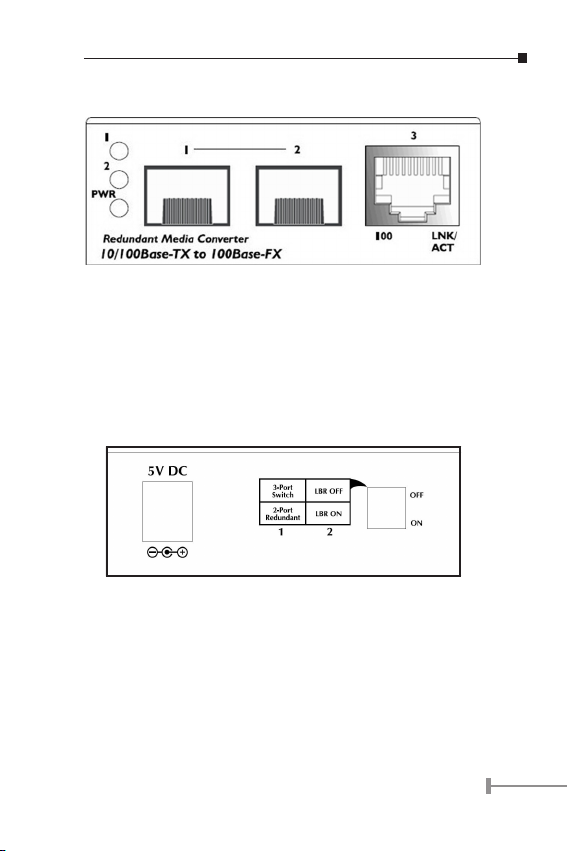
FT-1105A / FT-1205A Rear Panel
One DC jack for DC power input and DIP switch to set 3-Port
switch mode / 2-Port Redundant and Loop Back Reply enable/
disable function.
Page 9

6
Chapter 5
DIP SWITCH
There is a DIP switch for the setting on converter mode of copper
and fiber port. Refer to the table below for more details.
FT-1105A
Switch 1 On 2-Port Redundant (TP)
Off 3-Port Switch ( default )
Switch 2
On LBR ON
Off LBR OFF ( default )
2-Port Redundant ( FT-1105A)
When TP Redundancy is enabled, TP Port-2 and TP Port-3 are
configured as either forwarding or disabled. At any given time,
one port will be disabled and one port will be forwarding.
3-Port Switch
When TP Redundancy is disabled, all ports (Port-1, Port-2 and
Port-3) act as normal bridging ports.
LBR ( Loop Back Reply)
Enable/Disable the converter to reply for Loop Back Test.
Page 10

7
Chapter 6
INSTALLING THE CONVERTER
6.1 Stand-alone Installation
FT-1105A/FT-1205A is with high reliability and flexibility to
extend the distance up to 2Km, 20Km, or longer. It depends on
the 100Base-FX SFP transceiver modules. The SFP transceivers
are hot-plugable and hot-swappable. You can plug-in and out the
transceiver to/from any SFP port without having to power down
the converter.
To install a FT-1105A/FT-1205A stand-alone, on a desktop or
shelf, simply complete the following steps:
Step 1: Turn off the power of the device/station in a network to
which the FT-1105A / FT-1205A will be attached.
Step 2: Ensure that there is no activity in the network.
Step 3: Slot in the 100Base-FX SFP. Make sure both side of the
SFP transfer are with the same media type, for example:
100Base-FX/2km to 100Base-FX/2km, 100Bas-FX/20km
to 100Base-FX/20km.
Page 11

8
NOTE:
It recommends using PLANET MFB-FX series
100Base-FX SFP on the converter. If you insert
a SFP transceiver that is not supported, the
converter will not recognize it.
Step 4: Connect the fiber cable. Attach the duplex LC connector on
the network cable into the SFP transceiver.
Step 5: Attach fiber cable from the FT-1105A/FT-1205A to the
fiber network. TX, RX must be paired at both ends.
Step 6: Connect the 5VDC power adapter to the FT-1105A/FT-
1205A and verify that the Power LED lights up.
Step 7: Turn on the power of the device/station; the PWR LEDs
should light when all cables are attached.
NOTE:
Please refer to APPENDIX-A for detailed wiring
information of the FT-1105A/FT-1205A.
To prevent from optic acceptor malfunction,
check the both wires / transmitter before power
on the converter.
6.2 Chassis Installation and Rack Mounting
To install the media converter in a 10-inch or 19-inch with standard
rack, follow the instructions described below.
Step 1: Place your FT-1105A/FT-1205A on a hard flat surface, with
the front panel positioned towards your front side.
Page 12

9
Step 2: Carefully slide in the module until it is fully and firmly
fitted into the slot of the chassis.
Figure 6-2: Insert a media converter into an available slot
Step 3: Attach a rack-mount bracket to each side of the Chassis
with supplied screws attached to the package.
Step 4: After the brackets are attached to the chassis, use suitable
screws to securely attach the brackets to the rack, as
shown in Figure 6-2.
Step 5: Proceed with the steps 4 and steps 5 of session 6.1 Stand-
alone Installation to connect the network cabling and
supply power to your switch.
Caution:
You must use the screws supplied with the mounting
brackets. Damage caused to the parts by using
incorrect screws would invalidate your warranty.
Page 13

10
Chapter 7
Redundancy
The FT-1105A / FT-1205A provide less than 10 ms link redundancy
for highly critical Ethernet applications. The redundant-mode
supports auto-recover function. If the destination port of a packet
is link down, it forwards the packet to the other port of the backup
pair. The following figure shows the redundant function.
• Link status auto detect and redundant on Dual ports with
same connector type.
• Only Primary-Port is active at a time, the Backup-Port is
blocked.
• While Primary-Port link fail occur, the traffic swap to
Backup-Port automatically.
• Once the Primary-Port status back to link up, the traffic
swap from Backup-Port to Primary-Port.
Page 14

11
Chapter 8
Loop Back Reply
The FT-1105A / FT-1205A supports auto loop back reply while
receive loop back test packets on fiber port. Enable this function
to tell the converter to reply fiber signals request from Web
Smart media converter, such as PLANET FT-90x. You can use this
to check whether the converter can communicate with partner
converter. Please refer to the following figure.
Notice:
For FT-1105A only, while enable the Loop Back
Reply function, the Port-2 (TP) must be link up.
Page 15

12
Chapter 9
LED INDICATORS
The LED indicators give you instant feedback on status of the
converter:
■ System
LED Color Description
PWR Green Lit: Power on.
■ FT-1105A / FT-1205A -10/100Base-TX Port
LED Color Function
LNK/
ACT
Orange
Lit: Indicate that the port is link
up.
Blink: Indicate that the converter is
actively sending or receiving
data over that port.
Off: Indicate that the port is link
down.
100 Green Lit: Indicate that the port is
operating at 100Mbps.
Off: Indicate that the port is link
down or 10Mbps.
Page 16

13
■ FT-1105A -100Base-FX SFP Port
LED Color Function
LNK/
ACT
Green Lit: Indicate that the port is link up.
Blink: Indicate that the converter is
actively sending or receiving
data over that port
Off: Indicate that the port is link
down
FDX/
COL
Green Lit: Indicate that the connection
made through the corresponding
port is running in Full-Duplex
mode.
Off: Indicate that the connection
made through the corresponding
port is running in Half-Duplex
mode.
Page 17

14
■ FT-1205A -100Base-FX SFP Port
LED Color Function
1
2
Green Lit: Indicate that the port is link
up.
Blink: Indicate that the converter is
actively sending or receiving
data over that port
Off: Indicate that the port is link
down
Page 18

15
Chapter 10
PRODUCT SPECIFICATION
Model FT-1105A FT-1205A
Ports
Copper 2 x 10/100Base-
TX port
1 x 10/100Base-
TX port
Fiber 1 x 100Base-FX
port
2 x 100Base-FX
port
Optic Interface SFP SFP
Redundant Link Port 2 (Primary)
Port 3 (Backup)
Port 1 (Primary)
Port 2 (Backup)
Cable Twisted-
pair
10Base-T : 2-Pair UTP Cat. 3,4,5, up
to 100m
100Base-TX : 2-Pair UTP Cat. 5, 5e
up to 100m
Fiber-
optic
cable
• 50/125μm or 62.5/125μm multi-
mode fiber cable, up to 2km.
• 9/125μm single-mode cable, provide
long distance for 20/40/60km or
longer (very on SFP module)
Speed Twisted-
pair
10/20Mbps for Half/Full-Duplex
100/200Mbps for Half/Full Duplex
Fiber-
optic
200Mbps for Full-Duplex
Page 19

16
LED indicator System: One
Power LED,
TP Port :
• One Speed
• One LNK/ACT
Fiber Port:
• One Link/Act,
• One FDX/Col
System: One
Power LED,
TP Port :
• One Speed
• One LNK/ACT
Fiber Port:
• One Link/Act
DIP Switches DIP 1: On 3-Port Switch Mode
Off 2-Port Redundant
DIP 2: On Loop Back Reply Enable
Off Loop Back Reply Disable
Standards IEEE 802.3, 10Base-T
IEEE 802.3u, 100Base-TX, 100Base-FX
IEEE 802.3x Flow Control
APPENDIX A
A.1 Device‘s RJ-45 Pin Assignments
■ 10/100Mbps, 10/100Base-TX
Contact MDI MDI-X
1 1 (TX +) 3
2 2 (TX -) 6
3 3 (RX +) 1
6 6 (RX -) 2
4, 5, 7, 8 Not used Not used
Implicit implementation of the crossover function within a twistedpair cable, or at a wiring panel, while not expressly forbidden, is
beyond the scope of this standard.
Page 20

17
A.2 RJ-45 cable pin assignment
There are 8 wires on a standard UTP/STP cable and each wire is
color-coded. The following shows the pin allocation and color of
straight cable and crossover cable connection:
Figure A-1: Straight-Through and Crossover Cable
Please make sure your connected cables are with same pin
assignment and color as above picture before deploying the cables
into your network.
Page 21

18
A.3 Fiber Optical Cable Connection Parameter
The wiring details are as below:
■ Fiber Optical patch Cables:
Standard Fiber Type Cable
Specification
100Base-FX
(1310nm)
Multi-mode 50/125μm or
62.5/125μm
100Base-FX
(1310nm)
Multi-mode 50/125μm or
62.5/125μm
Single-mode 9/125μm
100Base-BX-U
(TX :1310/RX :1550)
100Base-BX-D
(TX :1550/RX :1310)
Single-mode 9/125μm
A.4 Power Information
The power jack of FT-1105A / FT-1205A is with 2.5mm in the
central post and required +5VDC power input. It will conform to
the bundled AC-DC adapter and Planet’s Media Chassis. Should
you have the problem to make the power connection, please
contact your local sales representative.
Please keep the AC-DC adapter as spare parts when your FT1105A / FT-1205A is installed to a Media Chassis.
2.5mm
DC Receptacle 2.5mm
+5V for each slot
Page 22

19
DC receptacle is 2.5mm wide that conforms to and matches the
Media Converter 2.5mm DC jack’s central post. Do not install any
improper unit, model of the Media Converter
A.5 Available Modules
The following list the available Modules for FT-1105A / FT-1205A
MFB-FX SFP-Port 100Base-FX Transceiver
(1310nm) -2km
MFB-F20 SFP-Port 100Base-FX Transceiver
(1310nm) – 20km
MFB-FA20 SFP-Port 100Base-BX Transceiver
(WDM,TX:1310nm) -20km
MFB-FB20 SFP-Port 100Base-BX Transceiver
(WDM,TX:1550nm) -20km
Page 23

2010-AA3520-000
Page 24

 Loading...