

Page 1

17" LCD Drawer KVM Console
with 8/16 Port Combo-Free Module
DKVM-1708/1716
1
Page 2

User’s Manual of DKVM-1708/1716
opyright
C
opyright (C) 2013 PLANET Technology Corp. All rights reserved.
C
he products and programs described in this User’s Manual are licensed products of PLANET
T
echnology, This User’s Manual contains proprietary information protected by copyright, and this
T
ser’s Manual and all accompanying hardware, software, and documentation are copyrighted.
U
o part of this User’s Manual may be copied, photocopied, reproduced, translated, or reduced to
N
ny electronic medium or machine-readable form by any means by electronic or mechanical.
a
cluding photocopying, recording, or information storage and retrieval systems, for any purpose
In
ther than the purchaser's personal use, and without the prior express written permission of
o
LANET Technology.
P
isclaimer
D
LANET Technology does not warrant that the hardware will work properly in all environments
P
and applications, and makes no warranty and representation, either implied or expressed, with
respect to the quality, performance, merchanta ility, or fitness for a particular purpose.
PLANET has made every effort to ensure that this User’s Manual is accurate; PLANET disclaims
liability for any inaccuracies or omissions that may have occurred.
Information in this User’s Manual is subject to nge without notice and does not represent a
commitment on the part of PLANET. PLANET assumes no responsibility for any inaccuracies
that may be contained in this User’s Manual. PLANET makes no commitment to update or keep
current the information in this User’s Manual, nd reserves the right to make improvements to
this User’s Manual and/or to the products described in this User’s Manual, at any time without
notice.
If you find information in this manual that is leading, or incomplete, we would
appreciate your comments and suggestions.
b
cha
a
incorrect, mis
FCC
This device has been tested and found to com
subject to the following two conditions:
(1) This device may not cause harmful interfere
(2) This device must accept any interference re
undesired operation.
ply with Part 15 of the FCC Rules. Operation is
nce
ceived. Including interference that may cause
CE
This equipment is in compliance with the requirements of the following regulations: EN 55 022:
CLASS A
EEE regulation W
To avo
presen
of electrical and electronic equipment should understand the meaning of the
crossed-out wheeled bin symbol. Do not dispose of WEEE as unsorted municipal
waste and have to collect such WEEE separately.
he potential effects on the environment and human health as a result of the
id t
ce of hazardous substances in electrical and electronic equipment, end users
Trademarks
The PLANET logo is a trademark of PLANET Technology. This documentation may refer to
numerous hardware and software products by their trade names. In most, if not all cases, these
designations are claimed as trademarks or registered trademarks by their respective companies.
Revision
User’s Manual for Drawer KVM Console with 8
M
odel: DKVM-1708/1716
Rev: 2.0
Part No
(January, 2013)
. EM-DKVM-1708/1716_v2.0
/16 Ports Combo-Free Module
II
Page 3

User’s Manual of DKVM-1708/1716
Safety Instructions
1. Please disconnect this equipment from AC outlet before cleaning. Don’t use liquid or
sprayed detergent for cleaning. Use moisture sheet or clothe for cleaning.
2. For pluggable equipment, the socked-outlet shall be installed near the equipment and
shall be easily accessible.
3. Please keep this equipment from humidity.
4. Lay this equipment on a reliable surface when install. A drop or fall could cause injury.
5. Do not leave this equipment in an environment unconditioned, storage temperature
above 60
6. The opening on the enclosure is for air convection hence the equipment from overheating.
DO NOT COVER THE OPENING.
7. Make sure the voltage of the power source connect the equipment to the power outlet.
8. Please keep the power cord such a way that people can not step on it. Do not place
anything over power cord. The power cord must rate for the voltage and current marked
o
C, it may damage the equipment.
on the product’s electrical ratings label. The voltage and current rating of the cord should
be greater than the voltage and the current rating marked on the product.
9. All cautions and warning on the equipment should be noted.
10. If the equipment is not in use for long time, disconnect the equipment from mains to avoid
being damaged by transient over-voltage.
11. Never pour any liquid into ventilation openings; this could cause fire or electrical shock.
12. Never open the equipment. For safety reason, qualified service personnel should only
open the equipment.
13. If one of the following situations arises, get the equipment checked by service personnel.
The Power Cord or plug is damaged.
Liquid has penetrated into the equipment.
The equipment has been exposed to moisture.
The equipment has not worked well or you can not get it work according to
User’s Manual.
The equipment has dropped and damaged.
If the equipment has obvious signs or breakage
III
Page 4

User’s Manual of DKVM-1708/1716
Index of Contents
Safety Instructions..................................................................................................................................
.... III
Index of Contents............................................................................................................................
1.
General Infor
1.1 Packing List.................................................................................................................................... 1
1.2 Product Feature...............................
1.3 Features ...................................................................
2. Installation ...........................................................................................................................................
2.1 Before I
2.2 Hardware Kits Contents.................................................................................................
2.3 LCD Components.................................................................................
2.4 Connecting the Console...............................................................................................................
3. OSD Operation.........................................................................
3.1 Panel Controls and LCD OSD Function....................................................................................... 1
3.2 KVM
3.2.1 Manual Key.......................................................................................................................
3.2.2 Hot Key and Mouse Clicking............................................................................................
3.2.3 OSD (On Screen Display).................................................................................................13
mation ............................................................................................................................. 1
................................................................................................ 2
....................................................................... 2
nstallation.......................................................................................................................... 6
.......................................... 9
........................................................... 11
OSD Function..................................................................................................................... 13
...........IV
................. 7
6
. 10
1
13
13
IV
Page 5

User’s Manual of DKVM-1708/1716
1. General Informat
ion
The PLANET DKVM-1708 / DKVM-1716 is the drawer KVM with single-rail
console design offering industrial level input solution, which optimizes your
space utilization by controlling your systems in just 1U space on the rack. The
sep
arate rail design helps users install the KVM console more easily. You don’t
hav
e to prop the heavy console during the installation but just lock the rails into
the
rack and then pull the KVM console into the rails. Simply use the supplied
Combo VGA cable set to link the ports to the console ports of your KVM switch,
no m
atter whether your connected port interface be either USB or PS/2.
The
KVM switch modules are loaded with rich features, such as one local
con
sole port, Daisy chain capability, On Screen Display (OSD) menu, Password
sec
urity, Searching PC server name, Hot key control, Push button and
Auto-Scan control, complete keyboard and mouse emulation for simultaneously
PC
boot-up processes.
1.1 Pa
cking List
The com
plete package consists of:
One 1.8 m KVM cable. (HDB-15 / VGA + PS/2 x 2)
One 1.8m power cord
One user’s manual CD
One quick installation guide
Two Rack mount bracket kit
One Rack Mount Screw pack
Check to make sure that the unit was not damaged in shipping. If you encounter a
problem, contact your dealer.
Please read this manual thoroughly, and follow the installation and operation
procedures carefully to prevent any damage to the product, and / or any of the
devices that connect to it.
1
Page 6

User’s Manual of DKVM-1708/1716
1.2 Product Feature
¾ Hardware
Heavy-Duty Electroplate Steel
Supports high resolution up to 1280 x 1 024 @ 75Hz
Complies with EIA RS-310C 19” Rack Mount standard
¾ System
Supports Combo KVM module to connect servers / KVM via USB & PS/2 connection
Fully supports Logitech / Microsoft / IBM PS/2 mouse / trackball and compatible PS/2 m
trackball
Supports hot plug; not necessary to turn off the original system regardless of a newl
PC or KVM
¾ Installation
ouse /
y installed
Single rail design
OSD function for
, easy to install
LCD display and KVM Switch
Cascade controls 128 sets of PCs
Supports 6 keyboard languages (continua
lly increase)
1.3 Features
Easy to install
With the unique separate rail desig
easily. In case you need to maintain the console, you can easily uninstall without
effecting the server above or below.
n. One man can install the KVM console
2
Page 7
User’s Manual of DKVM-1708/1716
odular KVM switches
M
The user can use
DKVM-1708/1716 as single port console or through some
simple action and few screws to be 8/16 ports KVM switch.
3
Page 8

User’s Manual of DKVM-1708/1716
Various keyboard language support
DKVM-1708/1716 provides multi-Language keyboard support English, Germany,
rench, Italian,Spanish,Chinese. F
erful Mouse/Keyboard Support
Pow
In the present computer applications, a mouse has become an indispensable
device. The KVM fully supports various models of PS/2 mice manufactured by
Logitech, Microsoft and IBM as well as compatible PS/2 mice of other brands.
The KVM supports the PS/2 Keyboard Port of the CODE SET1/2/3 and further
allows you to use the KVM for all kinds of servers, PCs or their combination.
4
Page 9

User’s Manual of DKVM-1708/1716
1.4 Product Specification
Model Name DKVM-1708 DKVM-1716
Display Size 17 inches
Panel Type 2CCFL LCD Panel
Resolution Capabilities Maximum Resolution up to 1280 x 1024 (SXGA)
Pixel Pitch Supports 0.264(H)x0.264(V)/ 0.294(H)x0.294(V)
Operating System
Multi Platform Support PS/2 and Combo-Free KVM module
System Cables KVM Cable(Combo-Free) x 1
Keyboard Mouse 105 key PS/2 keyboard with touch pad
Power Source 100 ~ 240V AC input
Touch pad 1000 points/ inch(40 points/mm)-graphics tablet mode
Mouse resolution 300 DPI
KVM Switch Module PC
Connectors
Temperature
Humidity 0% ~ 80% RH
Chassis Construction Heavy duty steel materials
Keyboard Language*
Certification CE / FCC
Windows 98SE/ME/2000/XP/2003/Vista/7 Server,Linux,
Mac OS9/OSX and Sun Microsystems.
Video: 8 HDB-15 female Video: 16 HDB-15 female
KB/MS: PS/2 & USB signal combined
Operate: 5 ~ 40 Degree C / 41 ~ 104 Degree F
Storage: -20 ~ 60 Degree C / -4 ~ 140 Degree F
Multi-Language keyboard support English, Germany, French,
Italian,Spanish,Chinese(Default: English)
5
Page 10

User’s Manual of DKVM-1708/1716
2. Installation
2.1 Before Inst
allation
1. Please eripherals accord
sure of the whole unit was not damaged and lost during shippi
you enc y problem, please contact your dealer.
2. Before instal , make sure all peripherals and computer have be
check all p ing the list before installation. To make
ng process. If
ountered an
lation en
turned off.
3. The standar kets are for 500 ~ 800 mm (dist
to rear bracke inet, contact your dealer if you nee
4. If your ca pth is above 800 to 1000 mm, please c
for the s and replace it for your demand.
5. Reliable access ies of ra
Particular attention s
connecti
6. The KVM sole are a little bit heavy, please prevent th
from falling down e people hurt
he console d
and t amage.
d brac ance means front bracket
t) cab d longer rear brackets.
binet de ontact your dealer
tretch rails
or ck-mounted equipment should be maintained.
ply co ect
ons to the
hould be given to sup nnections other than dir
branch circuit.
and con ese devices
during the installation. That may make som
6
Page 11

User’s Manual of DKVM-1708/1716
2.2 Hardware Kits C
1. Adjust rail with pull or p
ontents
ush to fit your cabinet
2
. Install front and rear bracket on cabinet.
. Repeat step 1~2 for the other side.
3
4. Pull the console until rails automatically are locked. When users hardly push
the console and it can be unlocked by the power is over 4kg.
5. ght at the same time) then users can
Pull and turn the lock knobs (left and ri
open console to operate.
7
Page 12

User’s Manual of DKVM-1708/1716
6. Put the KVM module into the c
onsole form the back. There are two ways to
install the KVM module in suitable position, users can fix KVM module with
the KVM accessories (Both sides) or the extra R
(
Bothsides).
ack- mounted Screws
KVM accessories (L& R) X2
Extra rack- mounted Screws X8
7. Finish installation as below.
8
Page 13

User’s Manual of DKVM-1708/1716
2.3 LCD Components
11
1
2
3
4
9
6
8
7
No. Component Function Description
Handle Holder Pull to Slide the LCD console in or out
1
LCD Display Panel Display
2
LCD Panel OSD Buttons Controls Display Required Quality
3
12
10
5
LED Indicators Switching Operation for KVM Module ( Optional )
4
Slide Rail Single Slide Rail
5
USB Ports x 2 (K/B, Mouse) Plug- in external K/B and Mouse.
6
Power LED Indicates Power Status
7
Power Switch Turn on / Turn off
8
Touch Pad Mouse Operation
9
Keyboard Module Keyboard Operation
10
LCD Lock Screws Fix or Release LCD panel
11
8/ 16 ports KVM Modular KVM for 8/ 16 ports
12
9
Page 14

User’s Manual of DKVM-1708/1716
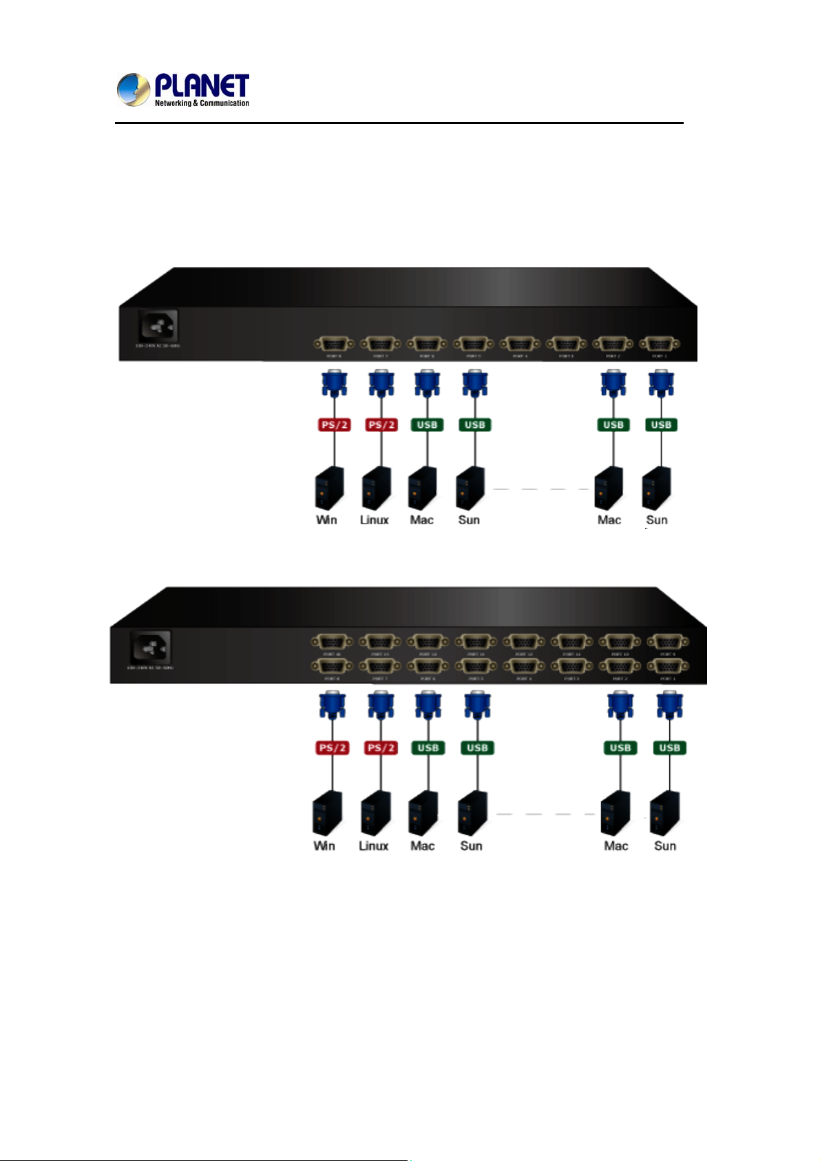
2.4 Connecting the Co
o connect an LCD console computer, perform the following steps
T to a
nsole
8 Port of KVM
16 Port of KVM
1. Turn off your computer. You should always turn off your computer before
connecting or disc
onnecting a device.
2.
Connect the video (VGA) connector of the KVM cable to the video card
connector on the rear pan
el of your computer.
3. e ect the PS/2 mous
Id ntify and conn e and PS/2 keyboard connector to the
correct PS/2 ports on the rear panel of your computer. Or you can use USB
int ac ter. (Us your interface.
erf e to connect your compu e PS/2-USB switch to select
The switch has to be on PS/2 side when you use PS/2 interface connector.)
Pl
ease don't plug PS/2 and USB cables at the same time
10
Page 15

User’s Manual of DKVM-1708/1716
3. OSD Operation
3.1 Panel Controls and LCD OSD Function
Controls Description
Soft power on/off button. Adjacent LED is lit when
on.
To access the main menu. This button also acts as
Menu
the “Enter” button.
Auto-synchronize and scale down display to any
Auto
valid factory preset timings.
▲UP Press to scroll the function you want to adjust.
▼DOWN Press to scroll the function you want to adjust.
Table 3.1 Panel Controls
Figure 3-1. OSD Control Bar
Controls Description
Automatically size, centers direction and fine tunes
AUTO
Video signal to eliminate “noise” and direction
BRIGHTNESS Adjusts back ground black level of the screen image
CONTRAST Adjusts for ground white level of the screen image
SHARPNESS Adjusts the clarity and focus of the screen image
H.POSITION Moves the screen image left or right
V.POSITION Moves the screen up or down
Adjusts image distortion appearing as vertical bars or
CLOCK
“noise” on the screen
PHASE Adjusts image distortion appearing as horizontal
11
Page 16

User’s Manual of DKVM-1708/1716
“noise” on the screen
COLOR
Adjusts
color temperatures for users
METER
Allows you to choose from among five languages as
LANGUAGE English, French , German , Ital
ia , Simplified Chinese,
Espanola, and Nederland
SPE Volume control AKER
OSD
st operation of up/down on the screen
Adju
V.POSITION
O
SD
Adjust operation o
f right/left on the screen
H.POSITION
OSD O E FF TIM OSD “time of staying” on the screen
RECALL factory sorting Returns all controls back to
SOURCE Analog/Digital signal choice
EXIT/SAVE Exit OSD control
12
Page 17

User’s Manual of DKVM-1708/1716
3.2 KVM OSD Function
3.2.1 Manual Key
It is the simple swi to press the Port Selection
st tching method. You just need
Switch on the front panel of the KVM. The Selection LED (Red) is on, indicating
that you are switching to the corresponding port.
The Port Selection Switch functions only when connected to a PC.
1.
u
2. If the O
can no
sw
it
3. Fo o Scan Mode, none of the Port Sele
r Aut ction Switches functions
ffline Skip of the OSD System Setting is Auto, then yo
make any switch when pressing an offline Por
t t Selection
ch.
3.2 nd Mouse Clicking
.2 Hot Key a
ot key and mouse clicking are applicable for switching a small section. You
H
an select the SVS (Smart View Setting) from the OSD of the PC first (for a
c
uick switch of PC) and use the keyboard (press the Ctrl key twice) or the
q
ouse (press and hold the middle button while pressing the left or right button)
m
switch to the previous or next set of PC.
to
the
The mouse must have at least 3 keys. As far as you select a PC with
SVS, you can use this method for the switch.
3.2.3 OSD (On Screen Display)
Press the NumLock on the keyboard twice or simultaneously press the Push
Buttons 1 and 2 of the Port Selection Switch on the KVM panel to start the OSD.
Use the key Up, Down and Enter keys on the keyboard to switch or directly
move the mouse to the target PC, and then double click the left button.
Additionally, you also can use the numeric keys to enter the direct switch. For
example, if you want to switch a PC to the Slave KVM port 04 under the Master
KVM port 03, then you can start the OSD and then directly enter 0304. If you
are using a standalone machine, then just enter the first two digits.
More OSD related information is given in the following OSD sections.
13
Page 18

tart
S
User’s Manual of DKVM-1708/1716
Press the NumLoc
enter the OSD.
to
If you have modified the Hot Key for starting the OSD and are unable
enter the OSD by pressing NumLock,
the System Setting to modify the options of the OSD Entry Hot K
using Port Selection Switch first, and then press F9 to enter into
If you have modified the Hot Key for starting the OSD and are unable to
the OSD by pressing
k twice or the Port Selection Switches 1 and 2 on the panel
then you can start the OSD by
enter
NumLock, then you can start the OSD by using the Port
Selection Switch first, and then press F9 to enter into the System Setting to
odify the options of the OSD Entry Hot Key.
m
peration
O
You can operate the options by keyboard or mouse. For the keyboard
operation, besides the common Up and Down keys, there are special functio
keys such as Enter, Space Bar, Function Key (F1, F4…) under the OSD
to
ey.
n
remark field. For the mouse operation, the left key refers to Enter and the right
key refers to Exit. For example, move the mo
use point to your desired PC, and
click the left key. The selection bar will move to that position and then click the
lef
t key again for the execution.
must use the keyboard to complete the two functions: Name
You
Edit and Password.
14
Page 19

User’s Manual of DKVM-1708/1716
2
3
4
03-04:Mail S 1
Menu
Master List
er 4
Switch
LIST: MASTER
PWR C# KVM NAME SVS
● 01 Admin ♁
● 02 Θ
● 03 04 Mail Group Ο
04 Θ
● 05 Peter ♁
● 06 08 Web Group Ο
● 07 16 Data Group Ο
08
Θ
) *↑↓: Move Space: Edit Esc: Exit
F1: Sm
art View Enter: Switching
F4: Auto Scan F9: System Setting
Press Enter
F5: Clear Name List
Slave List
03-04:Mail Ser 4
LIST: Mail Group
PWR C# KVM NAME SVS
● 01 Mail Ser 1 Θ
● 02 Mail Ser 2 Θ
● 03 Mail Ser 3 ♁
● 04
Mail Ser 4 ♁
) *↑↓: Move Space: Edit Esc: Exit
F1: Smart View Enter: Switching
F4: Auto Scan F9: System Setting
F5: Clear Name List
1 、This field provides the information of the currently connected PC. As shown
the figure above, 03 refer to the Port Number of the Master; 04 refer the Port
in
Number of the Slave; and Mail Ser 4 is th
e name of this PC defined by Users. If
15
Page 20

User’s Manual of DKVM-1708/1716
PC connects to the Master, then the number consists of the first two digits. If a
a
User has not gi
ven a name for the PC, the name field will be blank.
2、This field shows the list of the Master KVM or a certain set of Slave KVM
currently displayed on the OSD. We recommend you to give a name to the
Slav
e KVM, or else the display after LIST: will be blank.
3、Th he fields are
descri and indicates
normal p cted to the CPU
port.
is field shows the list of connections to the KVM, and t
bed below : PWR: It shows the status of power supply a
ower supply for the equipment (PC or KVM) conne
C#: y 01~08 and the
It shows the channel number; the DKVM-1708 will displa
DKV nnot display al a
M-1716 will display 01~08; 09~16 (Since the screen ca l at
time
, therefore you can use PgUp/PgDn to switch the pages).
KVM , it shows that a
: It shows the KVM model. If there is a number in this field
set of KVM connects to this port. The number 04 indicates Port 4 and 08
indicates Port 8 and 16 indicates Port 16 and so on.
NAME e Slave
KVM o from the
group “.”, “:”.
SVS: . The
SVS is allel. If this option
If the connected K
: It shows the name of the equipment, and users can name th
r C on their own. There are a total of 12 characters selec d P te
of “A~Z”, “a~z”, “0~9” , “+”, “-” , “*”, “/” , “=”, “[”,“]”, “,”,
Please use the CapsLock to toggle the upper and lower cases.
It shows the Smart View Setting; use ♁ to open and Θ to close
blank and not clickable if the KVM is connected in par
is set Hot Key Switch
or Mo he option by Auto Scan. You also can use
m
use Clicking or selecting t
ouse to click this field.
VM is not on, there will have no number in this field.
ke the switch by operating theto open, then you can ma
Selection BAR: It shows the selection bar (Green); you can use the ↑↓ keys on
16
Page 21

User’s Manual of DKVM-1708/1716
the board to move the selection bar, and the situated position indicates the
selected target for giving instructions. For example, if the selection ba
#05 and you press Enter, then the system will switch to that particular PC or
C
r points at
press the “Space BAR” to start editing the name. Press F4 to enable/disable
the SVS option.
、Instruction Hint Field:
4
) *↑↓:
(Move)
SPACE:
(Edit)
Use the ↑↓ keys on the keyboard or the mouse
move the selection bar
The “Space BAR” on the keyboard is used to start
editing the name of the PC or KVM.
to
ESC: Use the “Esc” key on the keyboard to exit the
(Exit) current option or exit OSD.
F4:
(Auto Scan)
Use the F4 key to run Auto Scan, and you can set
the residing time, channel display time and mode
of the Auto Scan from System Setting.
F9:
Use the F9 key to enter into the System Setting
(System Setting)
Menu.
F5: Use the F5 key to clear the v
(Clear Name List)
fields. If you clear the name list under the Master
screen, then you will also clear the name lists
under all slaves. If you clear the name list under a
certain slave, then you only clear the name list
under that particular Slave KVM.
F1:
It switches the Smart View Setting.
(Smart View)
alues of all Name
17
Page 22

User’s Manual of DKVM-1708/1716
‧System Setting Menu
System Setting
Channel Display
Full
Mode
Channel Display Tim 5 Sec
Auto Scan Time 5 Sec
OSD Entry Hot Key Number Lock
Hot Key Switching OFF
Mouse Clicking OFF
Beeper Sound ON
Offline Skip Manual
OSD Language English
Security Level None
Console Lock Time 5 Min
↑↓ Move
Space Change
Esc Exit
F1 Information
F4 OSD Position
F8 Restore Default Setting
Item Description Default Other Selection
For Port Switching, Auto Scan
Ch
annel Display D Close, the Monitor will
and OS
Number,
Full
Mode
show the Channel information
Name
and mode selection.
10Sec,
Channel Display
Time
It shows the time for displaying
channel information.
5 Sec
Always,
None
10Sec,
Auto Scan Time
For Auto Scan, it shows the
5 Sec
residing time for each port.
20Sec,
30Sec,
60Sec
OSD Entry Hot
Select to turn on the hot keys of
Scroll Lock,
NumLock
Key
the OSD control screen.
Shift, None
18
Page 23

User’s Manual of DKVM-1708/1716
Hot Ke
y
Turn on/o
the keyboard for switching
ff the “Ctrl” hot keys on
OFF ON
Switching
mputer functions.
co
rn on/off the keys of t
Tu he
M licking
B
Offline Skip
O Select the language for the OSD. English
SD Language
mouse for switching computer
functio
T sound
funct
Set the offline skip func
a
ns.
urn on/off the beeper
ion.
tion to
uto or manual.
OFF ON ouse C
ON OFF eeper Sound
Manual Auto
Select the security mode and
S
level.
None Low, High ecurity Level
Français,
Deutsch,
Italiano,
Español
Console Lock
1Min, 3Min,
Tim
e *1
The lock time of cons 5 Min
ole port.
10Min,
30Min, 60Min
*1: You can select this option only if el is not “None”.
Information; It provides the sion information,
F1: model name and F/W ver
hich is helpful for users to understand the updated version.
w
the Security Lev
F4: OSD Positio n to make adjustments; we
recommend you
this n aga u can use the Up, Down, Left
functio
or Right keys on use to move the OSD position.
n; you can enter the OSD positio
to unify the resolution for all comp
in to adjust the OSD position. Yo
the keyboard or a mo
uter lay mode
disp , and use
F8 a defau s. Ple
: Restore Def ult Setting; Restore the factory lt setting ase note
that all name lists will be cleared and the system settings are set to t ult
he defa
settings as shown in the table above.
Esc: Exit; Exit the system setting and close t f you h de
he OSD. I ave ma
changes in this option, the system will ask whether or not you want to save the
setting before th selected option is effective.
e
19
Page 24

User’s Manual of DKVM-1708/1716
A Mod press “F4” to enter the Auto
uto Scan
e: You can start the OSD first and
Scan Mode. If y u must us mart V etting
to select the
includes 5 sec, 1 0 sec. You can adjust the Channel
ou want to scan the PC, yo
Auto esiding time, which
Scan Time in the System Setting for the r
e the S iew S
0 sec, 20 sec, 30 sec and 6
n e Cha isplay . By
d Channel Display Time from thDisplay Mode a nnel D mode
then, all keys on the panel, keyboard and mouse are not operable. You can
only use the ESC key to exit the Auto Scan Mode.
Security Mode
Setting, and e
: “None” to “Low” in the System
Switch the Security Level from
nte (“A~Z”,“0~9”, a maximum of 12 characters),
r your Password
and the security will be effective after you confirm the Password. The use of the
Console Lock Time is to set the time to enter a security mode after th
keyboard and mouse has idled for a predetermined e. Once enter into
tim you
the security mode, you need to enter the correct password before yo
e
u can
move the mouse or enter any key from the keyboard. You need a correct
password to op rate th
e e whole system normally.
Important Not : What should I do if I forgot m sword
e y Pas ?
After you enter a wrong password for 5 consecutive times, a time de
pear, and a set of “Magic Numbers” will show up at the bottom. Record the
ap
lay bar will
magic numbers and contact with your distributor.
Console - Reconfirmed: Simultaneously press the largest two numbered Port
election Switches on the panel to start the Console- Reconfirmed. If you
S
change the Console equipment, please use this function to let KVM reconfirm
the equipment at the Console end once.
EDID & DDC: A vast majority of computer monitors supports the Extende
isplay Identification Data (EDID) and allows data access by Display Data
D
d
Channel (DDC). The KVM also supports these two specifications, but the KVM
only reads the EDID of the Monitor when the KVM is on. If it is necessary to
change monitors during an operation, p
nction to read the EDID again.
fu
lease use the Console Reconfirmed
20
 Loading...