

Page 1

UTM Content Security Gateway
CS-2001
Quick Installation Guide
Page 2

Table of Contents
1. Package Contents ........................................................................................ 3
2. Setup the UTM Content Security Gateway ...................................................... 4
3. Hardware Installation ................................................................................... 5
4. Basic System Conguration .......................................................................... 7
Page 3

1. Package Contents
CS-2001
CS-2001 x 1 l
Quick Installation Guide x 1 l
User’s Manual CD x 1 l
Power cord x 1 l
Console cable x 1 l
Cat5 Cable x 4 l
Screw Package x 1 l
Rack-mount ear x 2 l
Mat x 4 l
If any of above items are damaged or missing, please contact your dealer
immediately.
3
Page 4

4
2. Setup the UTM Content Security Gateway
The followings are instructions for setting up PLANET CS-2001. Refer to the
illustration and follow the simple steps below to quickly install your UTM Content
Security Gateway.
Safety Instruction
The following is the safety instructions for UTM Content Security Gateway before
installing.
>> The maximum operating temperature of the UTM is 50ºC. Care must be taken
to allow sufcient air circulation or space between units when the UTM is installed
inside a closed rack assembly and racks should safely support the combined weight
of all UTM.
>> The connections and equipment that supply power to the UTM should be
capable of operating safely with the maximum power requirements of the UTM.
In the event of a power overload, the supply circuits and supply wiring should not
become hazardous.
>> The AC power cord must plug into the right supply voltage. Make sure that
the supplied AC voltage is correct and stable. If the input AC voltage is over 10%
lower than the standard may cause the UTM to malfunction.
>> Generally, when installed after the nal conguration, the product must comply
with the applicable safety standards and regulatory requirements of the country in
which it is installed. If necessary, consult for technical support.
Page 5
5
3. Hardware Installation
UTM Content Security Gateway
CS-2001
Power
H.Disk
DTE,9600,n,8,1
USB
Port 1 Port 2
Port 3 Port 4
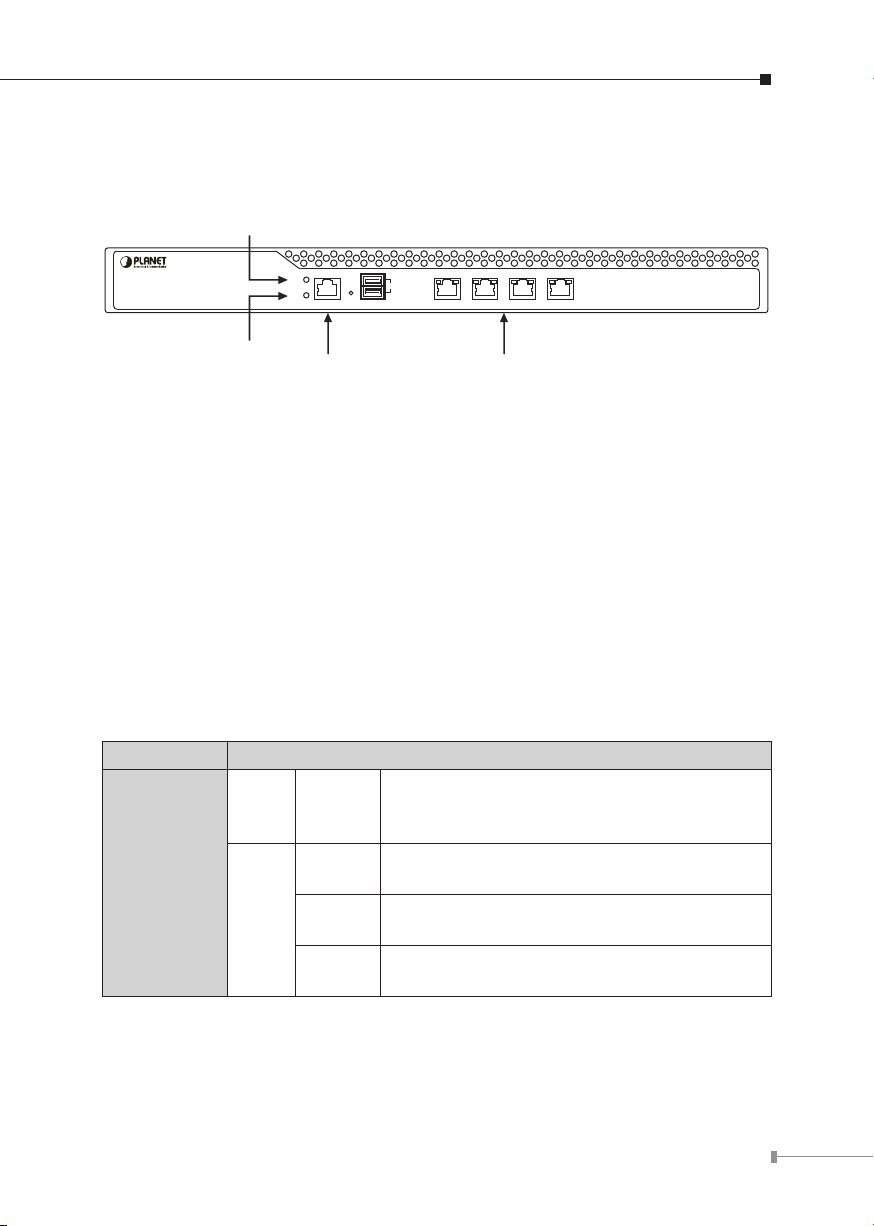
Power Indicator
HDD Indicator
HDD Indicator Ethernet Port1/2/3/4
Front panel:
Figure 1. Front Panel of the CS-2001
Power Indicator: Lights up when the power is on.
HDD Indicator: Glitters when system is accessing data from the HDD.
Console Port (9600, 8, N, 1): A RJ-45 console cable connect this serial port
for checking network interface setting and can reset to factory setting.
Ethernet Port 1/2/3/4 can be set as a:
LAN Port: Connects to the Intranet. l
WAN Port: Connects to the perimeter router. l
DMZ Port: The demilitarized zone (DMZ) is a physical subnet for securing the l
Local Area Network. It allows the externals users to access the company’s
external network.
LED / Port Description
WAN
LAN
DMZ
LED1 Orange
Orange
LED2
Green
Off
Steady on indicates the port is connected to
other network device.
Blink to indicates there is trafc on the port
Steady on indicates the port is connected at
1000Mbps speed
Steady on indicates the port is connected at
100Mbps speed
The LED off to indicate the port is connected
at 10Mbps speed
Page 6

6
CS-2001 Topology:
CS-2001
Vendor
Headquarters
Home
Branch Office
Mail-ServerFinance-Server Web-Server
DMZ
Access Point
Firewall GatewayFirewall Gateway
Modem
Modem
ModemPC
PC
PC
PC
Laptop
Laptop
001101010
IPSec VPN Tunnel
IPSec VPN Tunnel
SSL VPN Tunnel
Firewall
Access Point
Virus
Attack
Spam
001101010
001101010
Firewall
Internet
b/g
b/g
ADSL
ADSL
ADSL 2/2+
ADSL
100Base-TX UTP
1000Base-T UTP
2.4GHz 802.11b/g
b/g
Figure 2. Topology of the CS-2001
Page 7

7
4. Basic System Conguration
Step 1. Connect both the IT administrator’s PC and the device’s LAN port to the
same hub / switch, and launch a browser (e.g., IE or Firefox) to access
the management interface address which is set to http://192.168.1.1 by
default.
Step 2. You will be prompted for user name and password when accessing the
management interface. (both of user name and password are “admin” by
default)
Figure 3. Typing the User Name and Password
Page 8

8
Step 3. The user interface consists of the following two panels:
Note
Menu Panel: Presents all the available system congurations in a tree directory
structure. (see Overview of Functions)
Conguration Panel: Displays the data or congurable settings of the
corresponding item selected on the Menu Panel.
Figure 4. The CS-2001 User Interface
For your reference, you may configure your management address
based on the available subnet ranges below.
10.0.0.0 ~ 10.255.255.255
172.16.0.0 ~ 172.31.255.255
192.168.0.0 ~ 192.168.255.255
Page 9

9
Step 4. If it’s the rst time you’ve logged into the management interface, an
install wizard will appear to guide you through setting some of the basic
settings required. System > Conguration > Installation Wizard
Figure5. The Install Wizard
Setp 5. Select the language for the user interface and the default character
encoding.
Important
Figure6. Selecting the Language and Default Character Encoding
Any data saved on the interface will be saved as the selected
default character encoding if the device is unable to recognize the
encoding.
Page 10

10
Step 6. The LAN interface address must reect your network environment. The
defualt LAN interface is set to 192.168.1.x/24. However, if the LAN
interface was changed to 172.16.0.1 (subnet mask: 255.255.255.0), the
IT administrator must congure each PC in the subnet using an available
IP address from this subnet.
Setting: Select Port1 (LAN1).
Interface: Select LAN.
LAN Interface Mode: Select NAT / Routing Mode.
Fill in the IP Address and Netmask elds.
Important
Figure7. Interface Settings
Once the LAN interface is changed, please enter the new LAN IP
address in the browser next time when you log in the CS-2001
Web UI.
Page 11

11
Step 7. Congure the WAN Interface (please refer to your ISP for the settings).
Setting: Select Port2 (WAN1)
Interface: Select WAN
Connection Mode: Select the required mode
Congure the remaining settings.
Figure 8. The WAN Settings
Page 12

12
Step 8. Tick the Synchronize to an NTP Server box to ensure the system is
provided with the accurate time.
Figure 9. Time Settings
Page 13

13
Step 9. Enable Outgoing.
Figure 10. Enabling an Outgoing Policy
Go to Policy > Outgoing and congure as below:
Source Address: Select Inside_Any
Destination Address: Select Outside_Any
Service: Select ANY
Figure 11. A Policy Allowing LAN Users to Access Any External Network Services
Finally, congure all LAN PC addresses within the same domain as the LAN inter-
face address, which is also the default gateway address for the LAN. Or, simply
by using the DHCP to enable LAN PCs to obtain IP addresses, users may have
Internet access right after conguring DHCP. To congure any network policies,
please go to Policy Object and Policy.
Page 14

Step 10. Provide the following CS-2001 interface information to LAN users.
Figure 12. Settings Conrmation
Step 11. Settings complete.
14
Figure 13. Installation Wizard Completed
Page 15

This page is intentionally left blank
Page 16

This page is intentionally left blank
 Loading...