

Page 1

Multi-Homing Security Gateway User’s Manual
Multi-Homing Security
Gateway
CS-1000
User’s Manual
Page 2

Multi-Homing Security Gateway User’s Manual
Copyright
Copyright (C) 2006 PLANET Technology Corp. All rights reserved.
The products and programs described in this User’s Manual are licensed products of PLANET Technology, This User’s
Manual contains proprietary information protected by copyright, and this User’s Manual and all accompanying hardware,
software, and documentation are copyrighted.
No part of this User’s Manual may be copied, photocopied, reproduced, translated, or reduced to any electronic medium
or machine-readable form by any means by electronic or mechanical. Including photocopying, recording, or information
storage and retrieval systems, for any purpose other than the purchaser's personal use, and without the prior express
written permission of PLANET Technology.
Disclaimer
PLANET Technology does not warrant that the hardware will work properly in all environments and applications, and
makes no warranty and representation, either implied or expressed, with respect to the quality, performance,
merchantability, or fitness for a particular purpose.
PLANET has made every effort to ensure that this User’s Manual is accurate; PLANET disclaims liability for any
inaccuracies or omissions that may have occurred.
Information in this User’s Manual is subject to change without notice and does not represent a commitment on the part of
PLANET. PLANET assumes no responsibility for any inaccuracies that may be contained in this User’s Manual. PLANET
makes no commitment to update or keep current the information in this User’s Manual, and reserves the right to make
improvements to this User’s Manual and/or to the products described in this User’s Manual, at any time without notice.
If you find information in this manual that is incorrect, misleading, or incomplete, we would appreciate your comments and
suggestions.
CE mark Warning
This is a class B device, in a domestic environment, this product may cause radio interference, in which case the user
may be required to take adequate measures.
Trademarks
The PLANET logo is a trademark of PLANET Technology.
This documentation may refer to numerous hardware and software products by their trade names. In most, if not all cases,
these designations are claimed as trademarks or registered trademarks by their respective companies.
To avoid the potential effects on the environment and human health as a result of the presence of hazardous
substances in electrical and electronic equipment, end users of electrical and electronic equipment should
understand the meaning of the crossed-out wheeled bin symbol. Do not dispose of WEEE as unsorted
municipal waste and have to collect such WEEE separately.
Customer Service
For information on customer service and support for the Multi-Homing Security Gateway, please refer to the following
Website URL:
http://
www.planet.com.tw
Before contacting customer service, please take a moment to gather the following information:
♦ Multi-Homing Security Gateway serial number and MAC address
♦ Any error messages that displayed when the problem occurred
♦ Any software running when the problem occurred
♦ Steps you took to resolve the problem on your own
Revision
User’s Manual for PLANET Multi-Homing Security Gateway
Model: CS-1000
Page 3

Rev: 1.0 (April, 2006)
Multi-Homing Security Gateway User’s Manual
Part No. EM-CS1000v1
Page 4

Multi-Homing Security Gateway User’s Manual
Table of Contents
CHAPTER 1: INTRODUCTION ........................................................................................................................ 1
1.1 FEATURES...........................................................................................................................................................1
1.2 PACKAGE CONTENTS ..........................................................................................................................................2
1.3 MULTI-HOMING SECURITY GATEW AY FRONT VIEW ...........................................................................................3
1.4 MULTI-HOMING SECURITY GATEW AY REAR PANEL ...........................................................................................3
1.5 SPECIFICATION....................................................................................................................................................3
CHAPTER 2: GETTING STARTED .................................................................................................................. 5
2.1 WEB CONFIGURATION ........................................................................................................................................5
2.2 CONFIGURE WAN1 INTERFACE..........................................................................................................................6
2.3 CONFIGURE WAN2 INTERFACE..........................................................................................................................7
2.4 CONFIGURE DMZ INTERFACE ............................................................................................................................7
2.5 CONFIGURE POLICY............................................................................................................................................8
CHAPTER 3: WEB CONFIGURATION .......................................................................................................... 10
3.1 SYSTEM.............................................................................................................................................................10
3.1.1 Admin....................................................................................................................................................... 11
3.1.2 Permitted IPs..........................................................................................................................................13
3.1.3 Software Update....................................................................................................................................15
3.1.4 Setting .....................................................................................................................................................15
3.1.5 Date/Time................................................................................................................................................20
3.1.6 Multiple Subnet ......................................................................................................................................21
3.1.7 Route Table.............................................................................................................................................26
3.1.8 DHCP.......................................................................................................................................................27
3.1.9 Dynamic DNS.........................................................................................................................................29
3.1.10 Host Table.............................................................................................................................................31
3.1.11 Language ..............................................................................................................................................33
3.1.12 Logout ...................................................................................................................................................34
3.2 INTERFACE ........................................................................................................................................................34
3.2.1 LAN..........................................................................................................................................................34
3.2.2 WAN.........................................................................................................................................................35
3.2.3 DMZ.........................................................................................................................................................39
3.3 POLICY OBJECT ................................................................................................................................................40
3.3.1 Address...................................................................................................................................................40
3.3.1.1 LAN.................................................................................................................................................40
3.3.1.2 LAN Group.....................................................................................................................................42
Page 5

Multi-Homing Security Gateway User’s Manual
3.3.1.3 WAN............................................................................................................................................... 45
3.3.1.4 WAN Group...................................................................................................................................47
3.3.1.5 DMZ................................................................................................................................................50
3.3.1.6 DMZ Group.................................................................................................................................... 52
3.3.2 Service.....................................................................................................................................................54
3.3.2.1 Pre-defined....................................................................................................................................55
3.3.2.2 Custom...........................................................................................................................................56
3.3.2.3 Group..............................................................................................................................................58
3.3.3 Schedule.................................................................................................................................................60
3.3.4 QoS..........................................................................................................................................................62
3.3.5 Authentication......................................................................................................................................... 66
3.3.5.1 Auth Setting...................................................................................................................................66
3.3.5.2 Auth User.......................................................................................................................................67
3.3.5.3 Auth Group ....................................................................................................................................70
3.3.5.4 Radius Serve.................................................................................................................................73
3.3.5.5 POP3..............................................................................................................................................74
3.3.6 Content Blocking.................................................................................................................................... 75
3.3.6.1 URL Blocking.................................................................................................................................75
3.3.6.2 Scripts ............................................................................................................................................77
3.3.6.3 P2P.................................................................................................................................................78
3.3.6.4 IM....................................................................................................................................................79
3.3.6.5 Download.......................................................................................................................................79
3.3.6.6 Upload............................................................................................................................................80
3.3.7 Virtual Server.......................................................................................................................................... 81
3.3.7.1 Mapped IP.....................................................................................................................................82
3.3.7.2 Virtual Server.................................................................................................................................84
3.3.8 VPN..........................................................................................................................................................89
3.3.8.1 IPSec Autokey...............................................................................................................................89
3.3.8.2 PPTP Server..................................................................................................................................92
3.3.8.3 PPTP Client...................................................................................................................................95
3.3.8.4 T runk...............................................................................................................................................97
3.4 POLICY ............................................................................................................................................................158
3.4.1 Outgoing................................................................................................................................................158
3.4.2 Incoming................................................................................................................................................162
3.4.3 WAN To DMZ & LAN To DMZ............................................................................................................166
3.4.4 DMZ To WAN & DMZ To LAN............................................................................................................169
3.5 MAIL SECURITY...............................................................................................................................................173
3.5.1 Configure...............................................................................................................................................174
3.5.2 Anti-Spam .............................................................................................................................................177
Page 6

Multi-Homing Security Gateway User’s Manual
3.5.2.1 Setting..........................................................................................................................................178
3.5.2.2 Rule..............................................................................................................................................179
3.5.2.3 Whitelist........................................................................................................................................182
3.5.2.4 Blacklist........................................................................................................................................184
3.5.2.5 T raining.........................................................................................................................................187
3.5.2.6 Spam Mail....................................................................................................................................193
3.5.3 Anti-Virus............................................................................................................................................... 193
3.5.3.1 Setting..........................................................................................................................................193
3.5.3.2 Virus Mail.....................................................................................................................................194
3.6 IDP..................................................................................................................................................................195
3.6.1 Setting ...................................................................................................................................................195
3.6.2 Signature...............................................................................................................................................196
3.6.3 IDP Report............................................................................................................................................199
3.7 ANOMALY FLOW IP .........................................................................................................................................200
3.8 MONITOR.........................................................................................................................................................201
3.8.1 Log.........................................................................................................................................................201
3.8.1.1 T raf fic............................................................................................................................................ 201
3.8.1.2 Event ............................................................................................................................................203
3.8.1.3 Connection ..................................................................................................................................205
3.8.1.4 Log Backup..................................................................................................................................206
3.8.2 Accounting Report...............................................................................................................................208
3.8.2.1 Setting..........................................................................................................................................208
3.8.2.2 Outbound.....................................................................................................................................209
3.8.2.3 Inbound........................................................................................................................................212
3.8.3 Statistic..................................................................................................................................................214
3.8.3.1 WAN Statistics.............................................................................................................................215
3.8.3.2 Policy Statistics...........................................................................................................................216
3.8.4 Status.....................................................................................................................................................217
3.8.4.1 Interface Status.................................................................................................................................217
3.8.4.2 Authentication..............................................................................................................................218
3.8.4.3 ARP Table....................................................................................................................................219
3.8.4.4 DHCP Clients..............................................................................................................................219
Page 7

Multi-Homing Security Gateway User’s Manual
Chapter 1: Introduction
Thank you for purchasing new model of Planet’s Security Gateway CS-1000, a special designed of security
gateway, adopts Heuristics Analysis to filter spam and virus mail, auto-training system can raise identify rate
of spam, and built-in Clam virus scan engine can detect viruses, worms and other threats from email transfer.
CS-1000 does not just provide the same feature as the previous generation product CS-500, such as Content
Blocking to block specific URL, Scripts, IM/P2P program, IPSec and PPTP VPN server, QoS, Authentication
etc. Built-in two WAN interfaces allow CS-1000 to support outbound load balance and wan fail-over feature.
Furthermore, the VPN Trunk provides VPN fail-over and load balance features, that can offer a VPN
redundant mechanism to keep your VPN connection being on line.
CS-1000 not only can filter spam and virus mail, but also is a high performance VPN firewall. Moreover,
built-in IDP and firewall function can defense hacker and blaster attack from Internet or Intranet. The
completely function in one device can provide you an excellent security solution and the secure environment
than ever.
1.1 Features
♦ Anti-Spam Filtering: Multiple defense layers (Head Analysis, Text Analysis, Blacklist & Whitelist,
Bayesian Filtering, Spam Fingerprint, Checking sender account and IP address), and Heuristics Analysis
to block over 95% spam mail. Customizable notification options and spam mail report are provided for
administrator. Varied actions toward spam mail include: Delete, Deliver, and Forward. Built-in
auto-training system to rise identify rate of spam mail substantially.
♦ Anti-Virus Protection: Built-in Clam virus scan engine can detect viruses, worms, and other threats
from email transfer. Scan mission-critical content protocols-SMTP, POP3 in real time as traffic enters the
network to provide maximum protection. Customizable notification options and virus mail report are
provided for administrator. Varied actions toward spam mail include: Delete, Deliver, and Forward.
♦ VPN Connectivity: The security gateway support PPTP server/client and IPSec VPN. With DES, 3DES
and AES encryption and SHA-1 / MD5 authentication, the network traffic over public Internet is secured.
♦ VPN Trunk: VPN trunk function provides VPN load balance and VPN fail-over feature to keep the VPN
connection more reliable.
♦ Content Filtering: The security gateway can block network connection based on URLs, Scripts (The
Pop-up, Java Applet, cookies and Active X), P2P (eDonkey, Bit Torrent and WinMX), Instant
Messaging (MSN, Yahoo Messenger, ICQ, QQ and Skype) and Download. If there are new updated
version of P2P or IM software in client side, CS-1000 will detect the difference and update the Content
Filtering pattern to renew the filtering mechanism.
- 1 -
Page 8

Multi-Homing Security Gateway User’s Manual
♦ IDP: CS-1000 provides three kinds of the Signature to complete the intrusion detection system, user can
select to configure “Anomaly”, “Pre-defined” and “Custom” according to the current environment’s
request.
♦ Anti-Virus for HTTP, FTP, P2P, IM, NetBIOS: The CS-1000 not only can provide Anti-virus feature for
mail, it also can filter the virus from varied protocol. The virus pattern can be updated automatically or
manually.
♦ Policy-based Firewall: The built-in policy-based firewall prevent many known hacker attack including
SYN attack, ICMP flood, UDP flood, Ping of Death, etc. The access control function allowed only
specified WAN or LAN users to use only allowed network services on specified time.
♦ QoS: You can control the outbound and inbound Upstream/Downstream Bandwidth by configuring the
QoS based on the WAN bandwidth.
♦ Authentication: Web-based authentication allows users to be authenticated by web browser. User
database can be configured on the devices or through external RADIUS server.
♦ WAN Backup: The CS-1000 can monitor each WAN link status and automatically activate backup links
when a failure is detected. The detection is based on the configurable target Internet addresses.
♦ Outbound Load Balancing: The network sessions are assigned based on the user configurable load
balancing mode, including “Auto”, “Round-Robin”, “By Traffic”, “By Session” and “By Packet”. User can
also configure which IP or TCP/UDP type of traffic use which WAN port to connect.
♦ Multiple NAT: Multiple NAT allows local port to set multiple subnet works and connect to the Internet
through different WAN IP addresses.
1.2 Package Contents
The following items should be included:
CS-1000
CS-1000 x 1
Power Adapter x 1
Quick Installation Guide x 1
User’s Manual CD x 1
Console cable x 1
RJ-45 cable
Rack-mount ear
If any of the contents are missing or damaged, please contact your dealer or distributor immediately.
- 2 -
Page 9
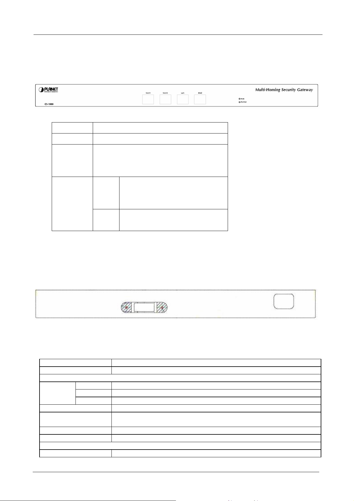
1.3 Multi-Homing Security Gateway Front View
CS-1000 Front Panel
LED Description
PWR Power is supplied to this device.
STATUS Blinks to indicate this devise is being turned on and
booting. After one minute, this LED indicator will stop
blinking, it means this device is now ready to use.
Multi-Homing Security Gateway User’s Manual
WAN1,
WAN2, LAN,
DMZ
Green Steady on indicates the port is connected
to other network device.
Blink to indicates there is traffic on the port
Orange Steady on indicates the port is connected
at 100Mbps speed
1.4 Multi-Homing Security Gateway Rear Panel
CS-1000 Rear Panel
1.5 Specification
Product Multi-Homing Security Gateway
Model CS-1000
Hardware
Ethernet
Power 100~250 VAC, 50~60 Hz, 0.6A
Operating Environment Temperature: 0~60°C
Dimension W x D x H, mm 237 x 440 x 43
Regulatory FCC, CE Mark
Software
Management Web
LAN 1 x 10/100 Based-TX RJ-45
WAN 2 x 10/100 Based-TX RJ-45
DMZ 1 x 10/100 Based-TX RJ-45
Relative Humidity: 5%~95%
- 3 -
Page 10

Multi-Homing Security Gateway User’s Manual
Network Connection Transparent mode (WAN to DMZ), NAT, Multi-NAT
Routing Mode Static Route, RIPv2
Concurrent Sessions 110,000
New session / second 10,000
Email Capacity per Day 120,000
Firewall Throughout 100Mbps
3DES Throughput 17Mbps
Firewall Policy-based firewall rule with schedule, NAT/NAPT, SPI firewall
VPN Tunnels 100/200
VPN Function PPTP server and client, IPSec
DES, 3DES and AES encrypting
SHA-1 / MD5 authentication algorithm
Remote access VPN (Client-to-Site) and Site to Site VPN
VPN Trunk
Content Filtering URL Blocking
Blocks Popup, Java Applet, cookies and Active X
P2P Application Blocking
Instant Message Blocking
Download Blocking
IDP Anti-Virus for HTTP, FTP, P2P, IM, NetBIOS
Automatic or manual update virus and signature database
Anomaly: Syn Flood, UDP Flood, ICMP Flood and more.
Pre-defined : Backdoor, DDoS, DoS, Exploit, NetBIOS and Spyware.
Custom: User defined based on TCP, UDP, ICMP or IP protocol.
Scanning Mail Settings The allowed size of scanned mail: 10 ~ 512Kbytes
Anti-Virus Email attachment virus scanning by SMTP, POP3
Inbound scanning for internal and external Mail Server
Action of infected mail: Delete, Deliver to the recipient, forward to an account
Automatic or manual update virus database
Anti-Spam Inbound scanning for external and internal Mail Server
Support Spam Fingerprint, Bayesian filtering, checking sender account and IP
to filter the spam mail
Black list and white list support auto training system
Action of spam mail : Delete, Deliver to the recipient, forward to an account
QoS Policy-based bandwidth management
Guarantee and maximum bandwidth with 3 priority levels
Classify traffics based on IP, IP subnet, TCP/UDP port
User Authentication Built-in user database with up to 200 entries
Support local database, RADIUS and POP3 authentication
Logs Log and alarm for event and traffic
Log can be saved from web, sent by e-mail or sent to syslog server
Accounting Report Record inbound and outbound traffic’s utilization by Source IP, Destination IP
and Service
Statistics Traffic statistics for WAN interface and policies
Graphic display
Others Dynamic DNS, NTP, DHCP server, Virtual server,
- 4 -
Page 11
Multi-Homing Security Gateway User’s Manual
Chapter 2: Getting Started
2.1 Web Configuration
STEP 1:
Connect both the Administrator’s PC and the LAN port of the Multi-Homing Security Gateway to a hub or
switch. Make sure there is a link light on the hub/switch for both connections. The Multi-Homing Security
Gateway has an embedded web server used for management and configuration. Use a web browser to
display the configurations of the Multi-Homing Security Gateway (such as Internet Explorer 4(or above) or
Netscape 4.0(or above) with full java script support). The default IP address of the Multi-Homing Security
Gateway is 192.168.1.1 with a subnet mask of 255.255.255.0. Therefore, the IP address of the Administrator
PC must be in the range between 192.168.1.2– 192.168.1.254
If the company’s LAN IP Address is not subnet of 192.168.1.0, (i.e. LAN IP Address is 172.16.0.1), then the
Administrator must change his/her PC IP address to be within the same range of the LAN subnet (i.e.
172.16.0.2). Reboot the PC if necessary.
By default, the Multi-Homing Security Gateway is shipped with its DHCP Server function enabled. This means
the client computers on the LAN network including the Administrator PC can set their TCP/IP settings to
automatically obtain an IP address from the Multi-Homing Security Gateway.
STEP 2:
Once the Administrator PC has an IP address as the same network as the Multi-Homing Security Gateway,
open up an Internet web browser and type in
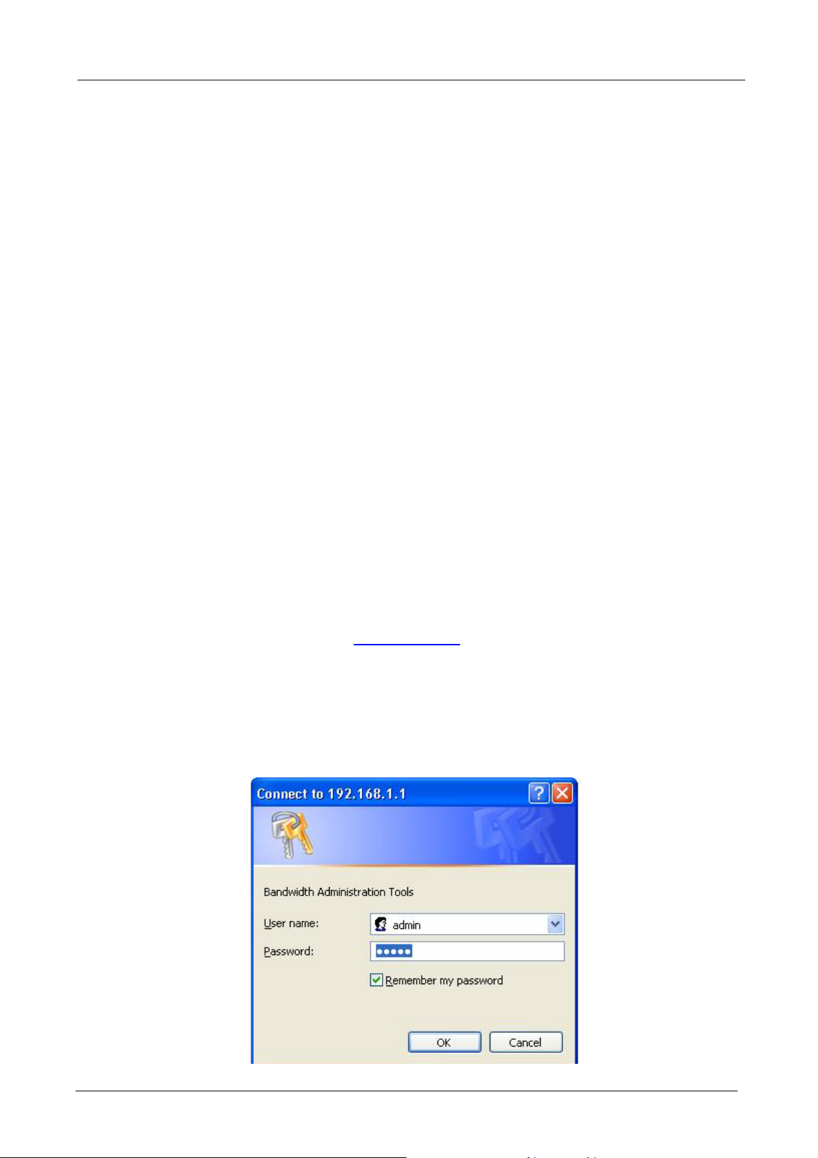
A pop-up screen will appear and prompt for a username and password. A username and password is required
to connect to the Multi-Homing Security Gateway. Enter the default login username and password of
Administrator (see below).
Username: admin
Password: admin
Click OK.
http://192.168.1.1 in the address bar.
- 5 -
Page 12
Multi-Homing Security Gateway User’s Manual
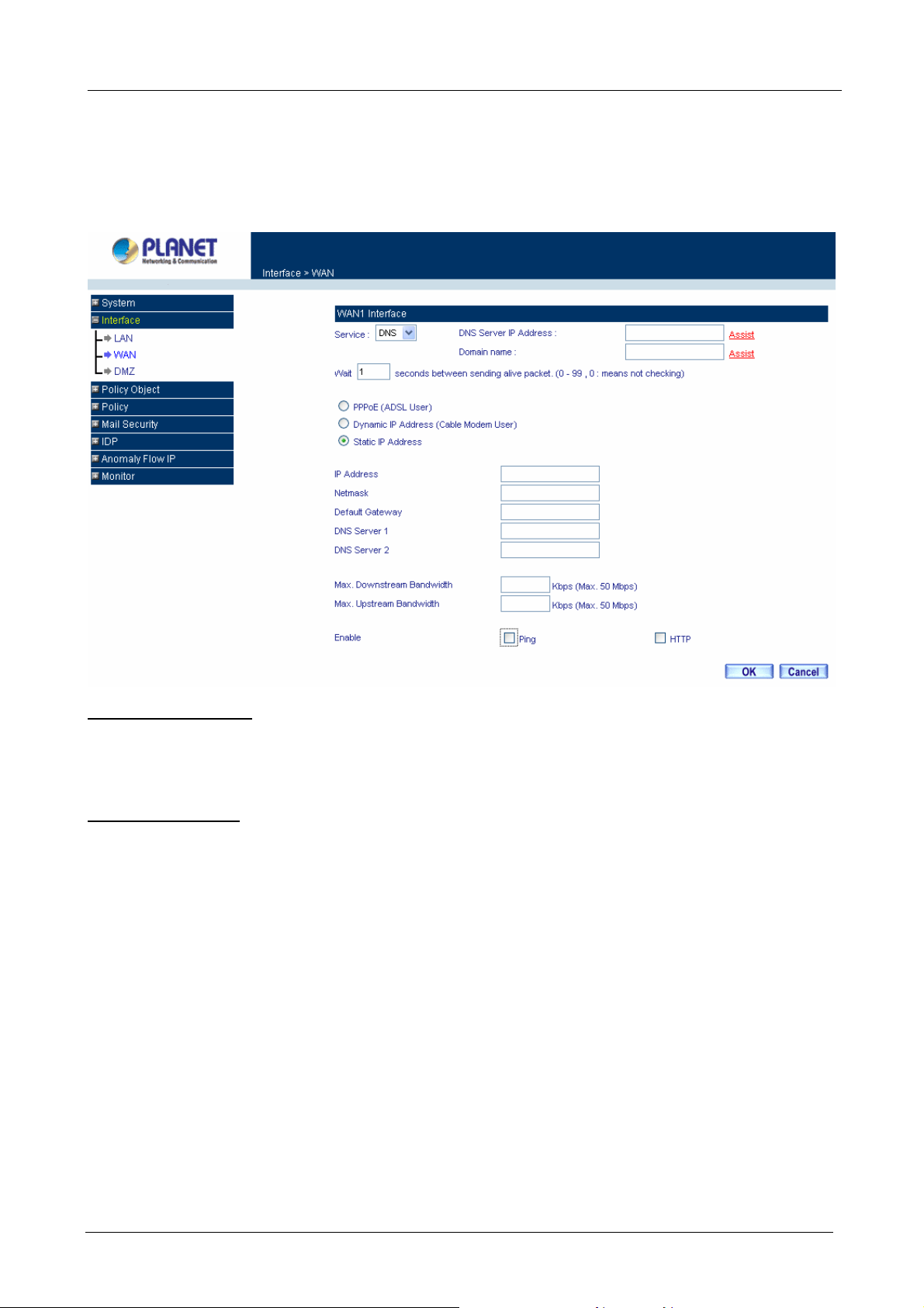
2.2 Configure WAN1 interface
After entering the username and password, the Multi-Homing Security Gateway WEB UI screen will display.
Select the Interface tab on the left menu then click on WAN below it.
Click on Modify button of WAN NO.1. The following page is shown.
Alive Indicator Site IP: This feature is used to ping an address for detecting WAN connection status.
Service: ICMP You can select an IP address by Assist, or type an IP address manually.
Service: DNS You can select a DNS IP and Domain name by Assist, or type the related data manually.
PPPoE (ADSL User): This option is for PPPoE users who are required to enter a username and password in
order to connect.
Username: Enter the PPPoE username provided by the ISP.
Password: Enter the PPPoE password provided by the ISP.
IP Address provided by ISP:
Dynamic: Select this if the IP address is automatically assigned by the ISP.
Fixed: Select this if you were given a static IP address. Enter the IP address that is given to you by
your ISP.
Max. Upstream/Downstream Bandwidth: The bandwidth provided by ISP.
Service-On-Demand:
The PPPoE connection will automatically disconnect after a length of idle time (no activities). Enter in
the amount of idle minutes before disconnection. Enter ‘0’ if you do not want the PPPoE connection to
disconnect at all.
- 6 -
Page 13

Multi-Homing Security Gateway User’s Manual
For Dynamic IP Address (Cable Modem User): This option is for users who are automatically assigned an
IP address by their ISP, such as cable modem users. The following fields apply:
MAC Address: This is the MAC Address of the device. Some ISPs require specified MAC address. If the
required MAC address is your PC’s, click Clone MAC Address.
Hostname: This will be the name assign to the device. Some cable modem ISP assign a specific
hostname in order to connect to their network. Please enter the hostname here. If not required by your
ISP, you do not have to enter a hostname.
Domain Name: You can specify your own domain name or leave it blank.
User Name: The user name is provided by ISP.
Password: The password is provided by ISP.
Max. Upstream/Downstream Bandwidth: The bandwidth provided by ISP.
For Static IP Address: This option is for users who are assigned a static IP Address from their ISP. Your ISP
will provide all the information needed for this section such as IP Address, Netmask, Gateway, and DNS. Use
this option also if you have more than one public IP Address assigned to you.
IP Address: Enter the static IP address assigned to you by your ISP. This will be the public IP address of
the WAN port of the device.
Netmask: This will be the Netmask of the WAN network. (i.e. 255.255.255.0)
Default Gateway: This will be the Gateway IP address.
Domain Name Server (DNS): This is the IP Address of the DNS server.
Max. Upstream/Downstream Bandwidth: The bandwidth provided by ISP.
Ping: Select this to allow the WAN network to ping the IP Address of the Multi-Homing Security Gateway. This
will allow people from the Internet to be able to ping the Multi-Homing Security Gateway. If set to enable, the
device will respond to echo request packets from the WAN network.
HTTP: Select this will allow the WebUI to be configured from a user on the Internet. Keep in mind that the
device always requires a username and password to enter the WebUI.
2.3 Configure WAN2 interface
If you want to connect WAN 2 to another ISP connection, click Modify button of WAN No. 2 then repeat above
procedures to setup.
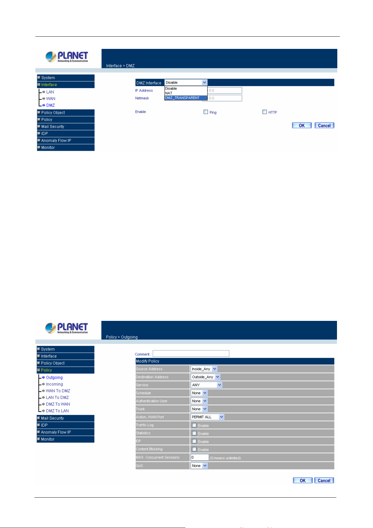
2.4 Configure DMZ interface
Depends on your network requirement, you can disable the DMZ port, make DMZ port transparent to WAN or
enable NAT function on it.
To configure the DMZ port, select the Interface tab on the left menu, then click on DMZ, the following page is
shown.
- 7 -
Page 14
Multi-Homing Security Gateway User’s Manual
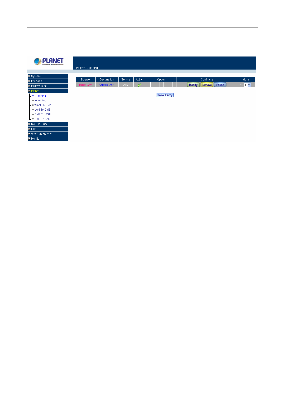
2.5 Configure Policy
STEP 1:
Click on the Policy tab from the main function menu, and then click on Outgoing (LAN to WAN) from the
sub-function list.
STEP 2:
Click on New Entry button.
STEP 3:
When the New Entry option appears, enter the following configuration:
Source Address – select “Inside_Any”
Destination Address – select “Outside_Any”
Service - select “ANY”
Action - select “Permit, ALL”
Click on OK to apply the changes.
- 8 -
Page 15
Multi-Homing Security Gateway User’s Manual
STEP 4:
The configuration is successful when the screen below is displayed.
Please make sure that all the computers connected to LAN port must set their Default Gateway IP Address to
the Multi-Homing Security Gateway’s LAN IP Address (i.e. 192.168.1.1). At this point, all the computers on the
LAN network should gain access to the Internet immediately. If a Multi-Homing Security Gateway filter
function is required, please refer to the Policy section in chapter 3.
- 9 -
Page 16

Multi-Homing Security Gateway User’s Manual
Chapter 3: Web Configuration
3.1 System
The Multi-Homing Security Gateway Administration and monitoring configuration is set by the System
Administrator. The System Administrator can add or modify System settings and monitoring mode. The sub
Administrators can only read System settings but not modify them. In System, the System Administrator can:
1. Add and change the sub Administrator’s names and passwords;
2. Back up all Multi-Homing Security Gateway settings into local files;
“System” is the managing of settings such as the privileges of packets that pass through the Multi-Homing
Security Gateway and monitoring controls. Administrators may manage, monitor, and configure Multi-Homing
Security Gateway settings. All configurations are “read-only” for all users other than the Administrator; those
users are not able to change any settings for the Multi-Homing Security Gateway.
System setting can divide into two parts: Administration, Configure and Logout.
Administration:
Admin: controls user access right to the Multi-Homing Security Gateway. User can add/remove users and
change passwords.
Permitted IPs: Enables the Administrator to authorize specific internal/external IP address(es) for gateway
managing.
Software Update: The administrator can update the device’s software with the latest version downloaded
from Planet’s website, in order to optimize the performance and keep up with the latest fixes for intruding
attacks.
Configure:
Setting: The Administrator may use this function to backup Multi-Homing Security Gateway configurations
and export (save) them to a computer; or restore a configuration file to the device; or reset the Multi-Homing
Security Gateway back to default factory settings. Under Setting, the Administrator may enable e-mail alert
notification. This will alert Administrator(s) automatically whenever the Multi-Homing Security Gateway has
experienced unauthorized access or a network hit (hacking or flooding). Once enabled, an IP address of a
SMTP (Simple Mail Transfer protocol) Server is required. Up to two e-mail addresses can be entered for the
alert notifications.
Date/Time: This function enables the Multi-Homing Security Gateway to be synchronized based on an
Internet Time Server or with the client computer’s clock.
Multiple Subnet: This function allows local port to be set with multiple IP subnet, and allow all clients
connecting to the internet via WAN IP Address.
Route Table: Use this function to configure static route for the networks when the dynamic route is not
efficient enough.
- 10 -
Page 17
Multi-Homing Security Gateway User’s Manual
DHCP: Administrator can configure DHCP (Dynamic Host Configuration Protocol) settings for the LAN (LAN)
network.
Dynamic DNS: The Dynamic DNS (require Dynamic DNS Service) allows you to alias a dynamic IP address
to a static hostname, allowing your device to be more easily accessed by specific name. When this function is
enabled, the IP address in Dynamic DNS Server will be automatically updated with the new IP address
provided by ISP.
Host Table: The Multi-Homing Security Gateway Administrator may use the Host Table function to make the
Multi-Homing Security Gateway act as a DNS Server for the LAN and DMZ network. All DNS requests to a
specific Domain Name will be routed to the Multi-Homing Security Gateway’s IP address. For example, let’s
say an organization has their mail server (i.e., mail.planet.com.tw) in the DMZ network (i.e. 192.168.10.10).
The outside Internet world may access the mail server of the organization easily by its domain name,
providing that the Administrator has set up Virtual Server or Mapped IP settings correctly. However, for the
users in the LAN network, their WAN DNS server will assign them a public IP address for the mail server. So
for the LAN network to access the mail server (mail.planet.com.tw), they would have to go out to the Internet,
then to come back through the Multi-Homing Security Gateway to access the mail server. Essentially, the LAN
network is accessing the mail server by a real public IP address, while the mail server serves their request by
a NAT address and not a real one. This odd situation occurs when there are servers in the DMZ network and
they are bound to real IP addresses. To avoid this, set up Host Table so all the LAN network computers will
use the Multi-Homing Security Gateway as a DNS server, which acts as the DNS Proxy.
Language: Both Chinese and English are supported in the Multi-Homing Security Gateway.
Logout:
Logout: Administrator logs out the Multi-Homing Security Gateway. This function protects your system while
you are away.
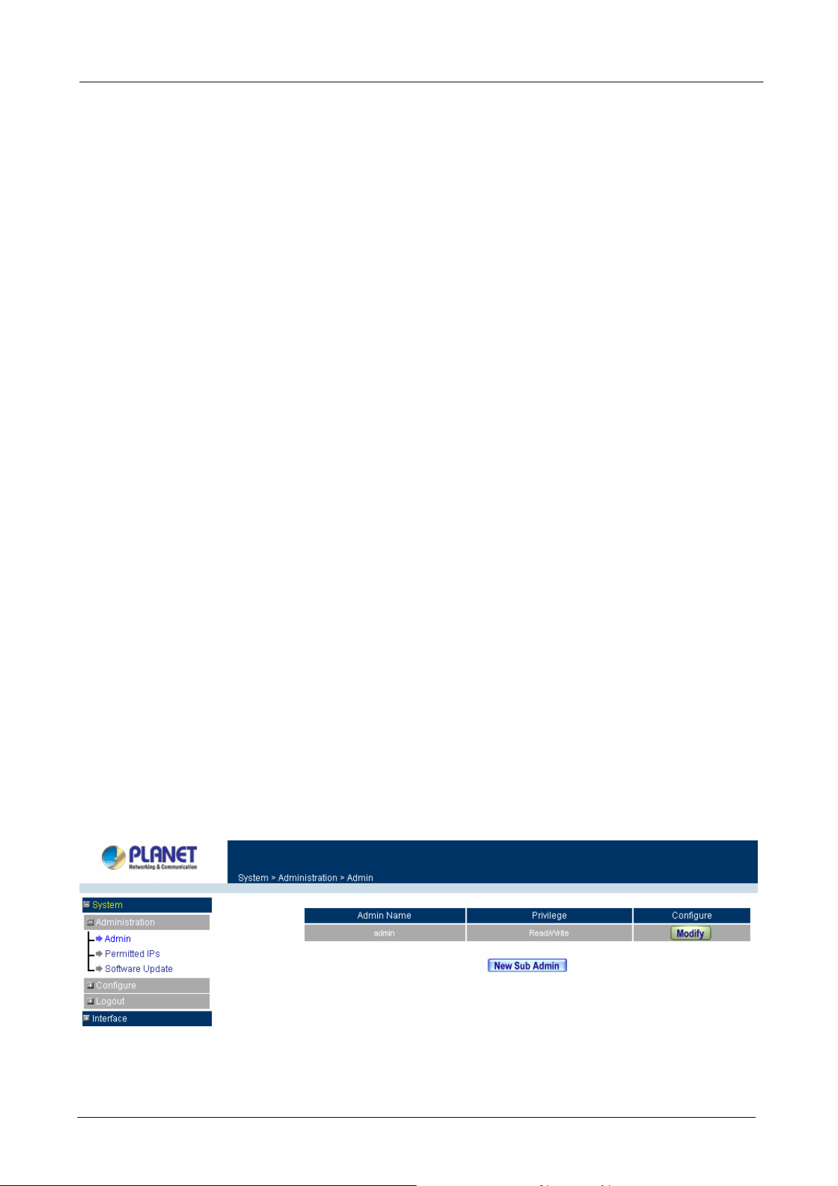
3.1.1 Admin
On the left hand menu, click on Administration, and then select Admin below it. The current list of
Administrator(s) shows up.
ÍÍ
- 11 -
Page 18
Multi-Homing Security Gateway User’s Manual
Settings of the Administration table
Admin Name: The username of Administrators for the Multi-Homing Security Gateway. The user admin
cannot be removed.
Privilege: The privileges of Administrators (Admin or Sub Admin)
The username of the main Administrator is Admin with read / wri te privilege.
Sub Admin may be created by clicking
New Sub Admin
. Sub Admin have read only privilege.
Configure: Click Modify to change the “Sub Admin” password and click Remove to delete a “Sub Admin”.
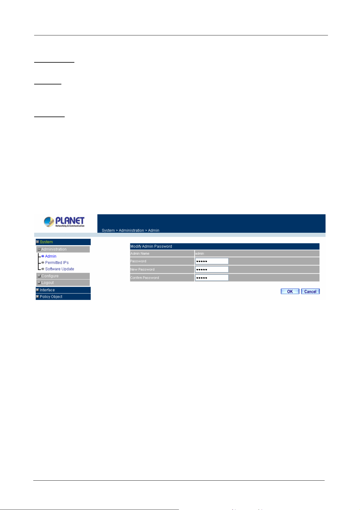
Changing the Main/Sub-Admin’s Password
Step 1. The Modify Admin Password window will appear. Enter in the required information:
Password: enter original password.
New Password: enter new password
Confirm Password: enter the new password again.
Step 2. Click OK to confirm password change or click Cancel to cancel it.
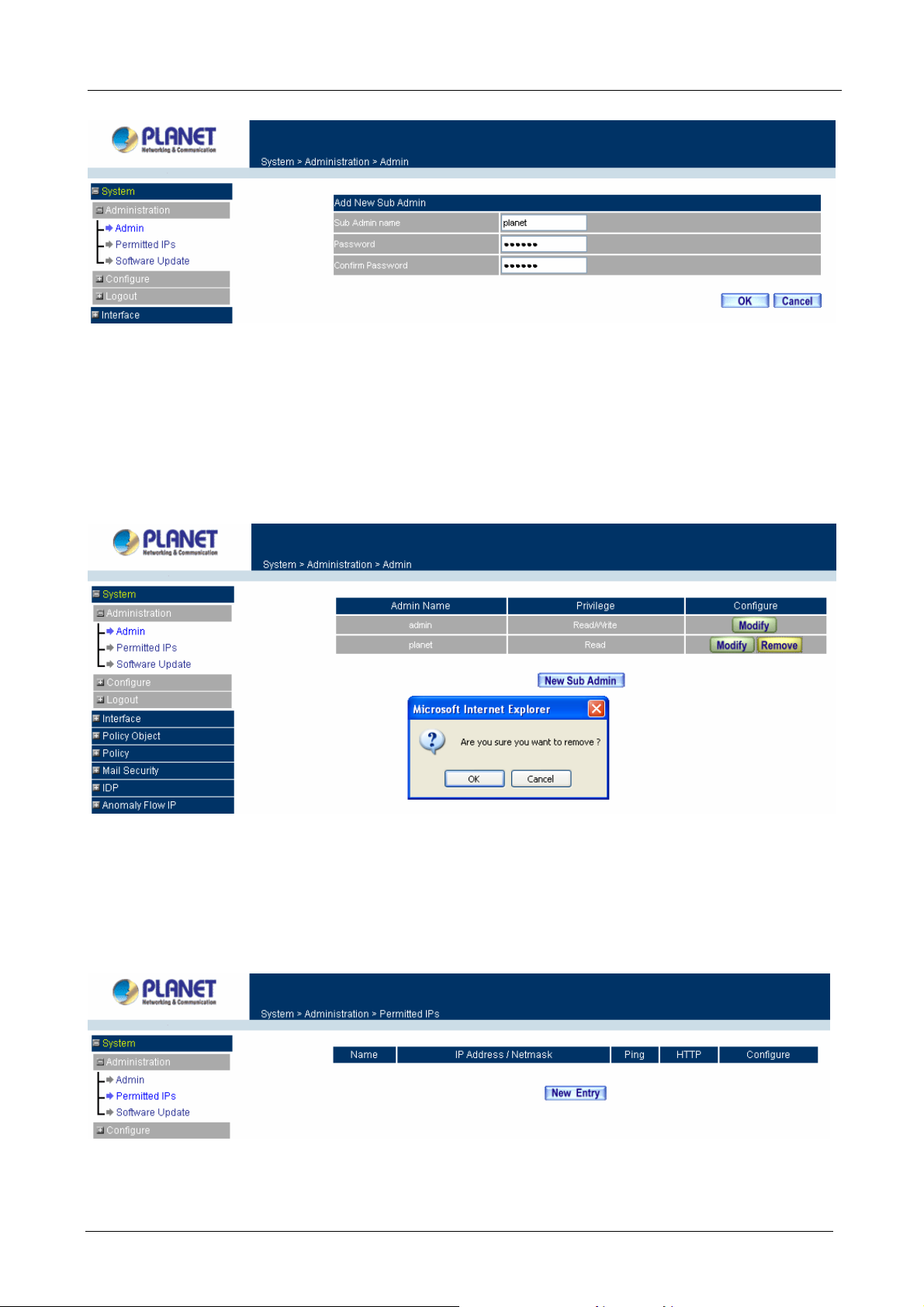
Adding a new Sub Admin
Step 1. In the Add New Sub Admin window:
Sub Admin Name: enter the username of new Sub Admin.
Password: enter a password for the new Sub Admin.
Confirm Password: enter the password again.
Step 2. Click OK to add the user or click Cancel to cancel the addition.
- 12 -
Page 19
Multi-Homing Security Gateway User’s Manual
Removing a Sub Admin
Step 1. In the Administration table, locate the Admin name you want to edit, and click on the Remove
option in the Configure field.
Step 2. The Remove confirmation pop-up box will appear. Click OK to remove that Sub Admin or click
Cancel to cancel.
3.1.2 Permitted IPs
Only the authorized IP address is permitted to manage the Multi-Homing Security Gateway.
ÍÍ
Add Permitted IPs Address
Step 1. Click New Entry button.
- 13 -
Page 20
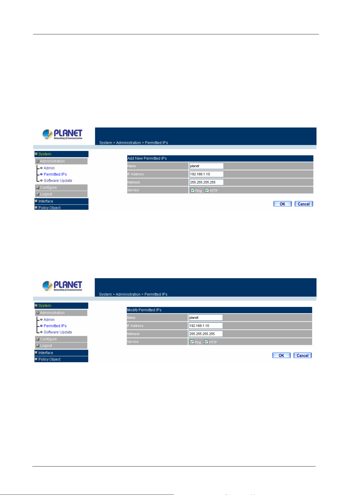
Multi-Homing Security Gateway User’s Manual
Step 2. In IP Address field, enter the LAN IP address or WAN IP address.
Name: Enter the host name for the authorized IP address.
IP Address: Enter the LAN IP address or WAN IP address.
Netmask: Enter the netmask of LAN/WAN.
Ping: Select this to allow the external network to ping the IP Address of the Firewall.
HTTP: Check this item, Web User can use HTTP to connect to the Setting window of
Multi-Homing Security Gateway.
Step 3. Click OK to add Permitted IP or click Cancel to discard changes.
Modify Permitted IPs Address
Step 1. In the table of Permitted IPs, highlight the IP you want to modify, and then click Modify.
Step 2. In Modify Permitted IPs, enter new IP address.
Step 3. Click OK to modify or click Cancel to discard changes.
Remove Permitted IPs Addresses
Step 1. In the table of Permitted IPs, highlight the IP you want to remove, and then click Remove.
Step 2. In the confirm window, click OK to remove or click Cancel to discard changes.
- 14 -
Page 21
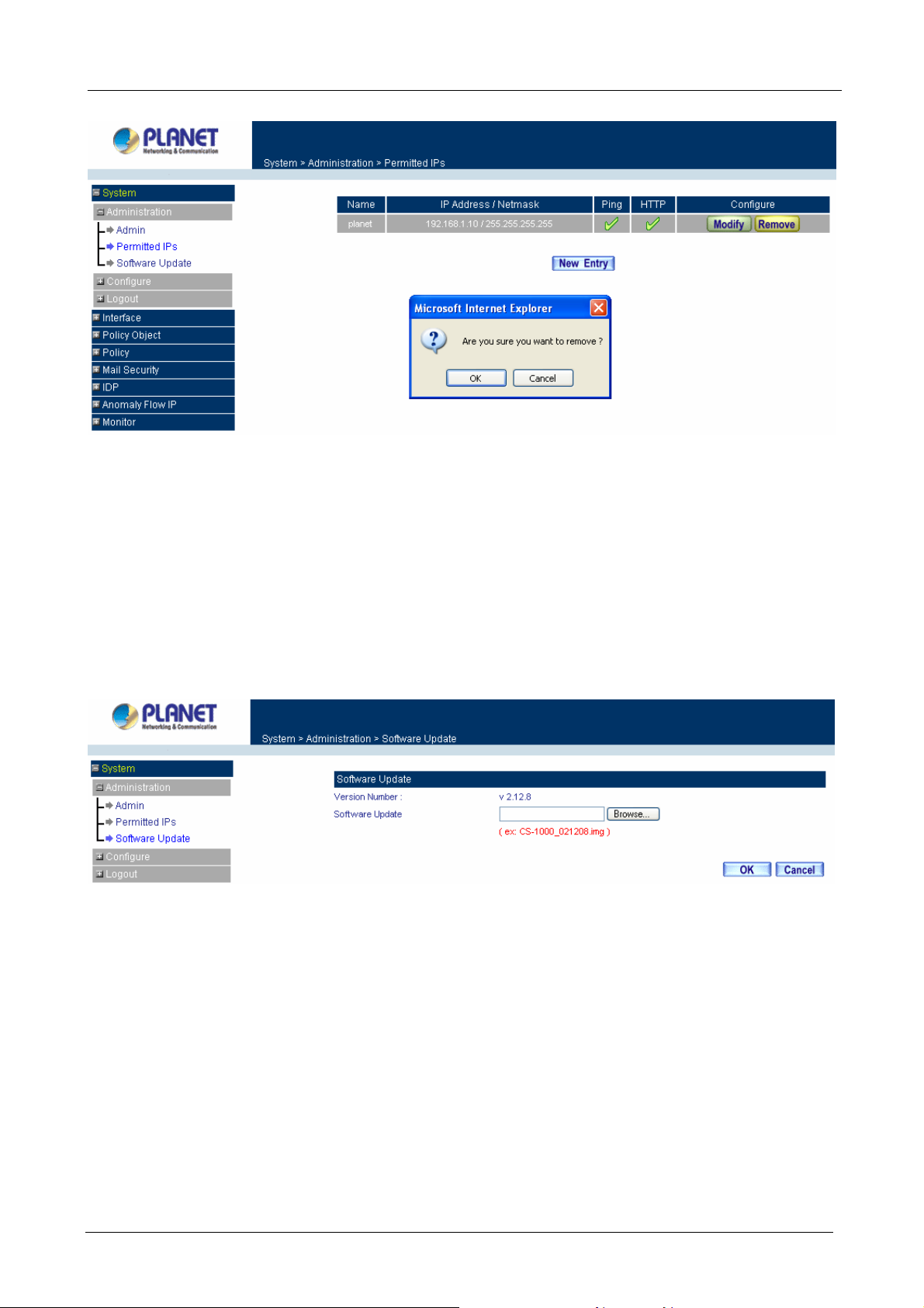
3.1.3 Software Update
Multi-Homing Security Gateway User’s Manual
Under Software Update, the admin may update the device’s software with newer software. You may acquire
the current version number of software in Version Number. Administrators may visit Planet’s website to
download the latest version and save it in server’s hard disk.
Step 1. Click Browse to select the latest version of Software.
Step 2. Click OK to update software.
ÍÍ
NOTE: It takes three minutes to update the software. The system will restart automatically after updating the
software.
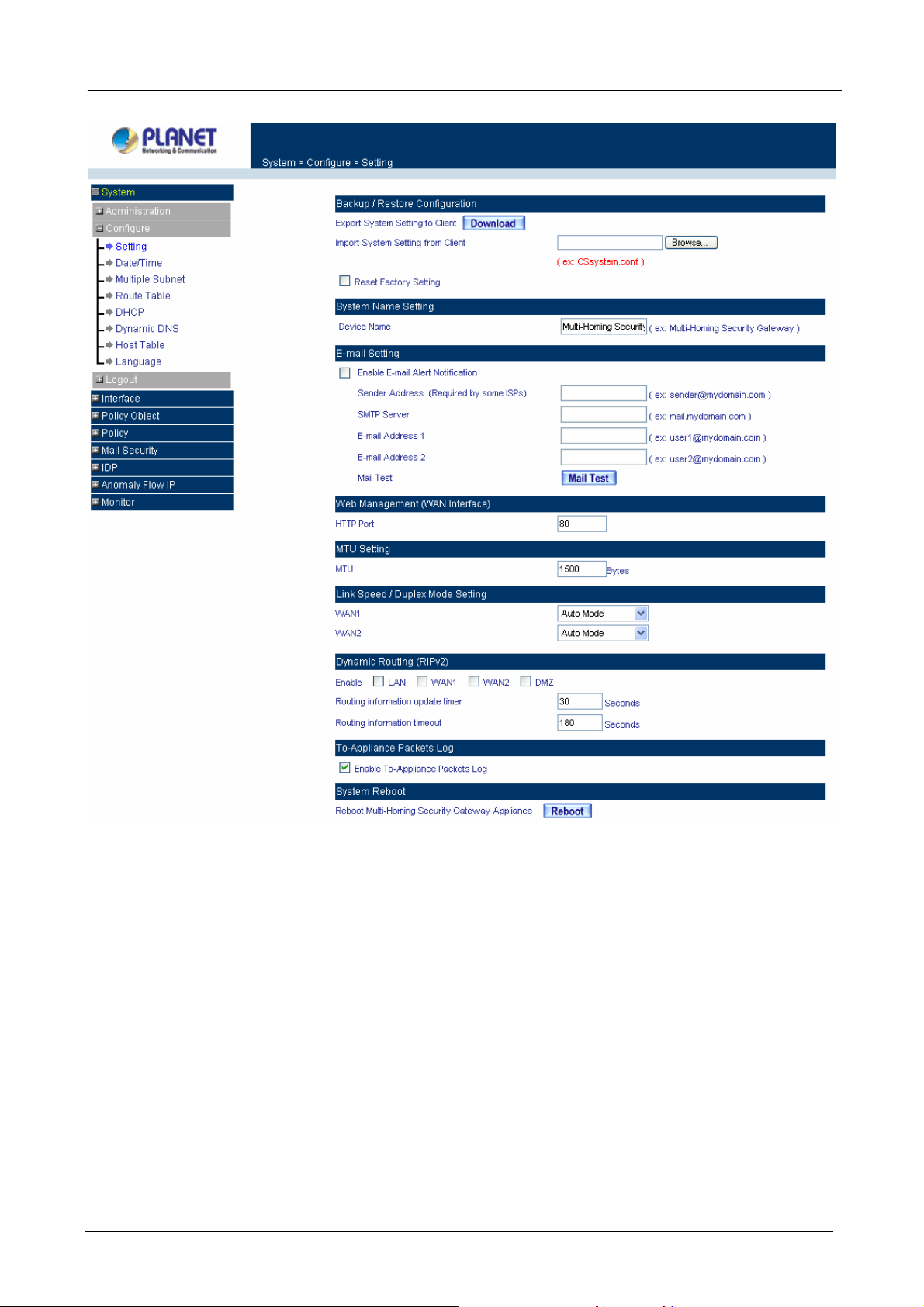
3.1.4 Setting
The Administrator may use this function to backup Multi-Homing Security Gateway configurations and export
(save) them to the “Administrator” computer or anywhere on the network; or restore a configuration file to
the device; or restore the Multi-Homing Security Gateway back to default factory settings.
Entering the Settings window
Click Setting in the Configure menu to enter the Settings window. The Setting will be shown on the screen.
- 15 -
Page 22
Multi-Homing Security Gateway User’s Manual
Exporting Multi-Homing Security Gateway settings
Step 1. Under Backup/Restore Configuration, click on the Download button next to Export System
Settings to Client.
Step 2. When the File Download pop-up window appears, choose the destination place to save the
exported file. The Administrator may choose to rename the file if preferred.
- 16 -
Page 23
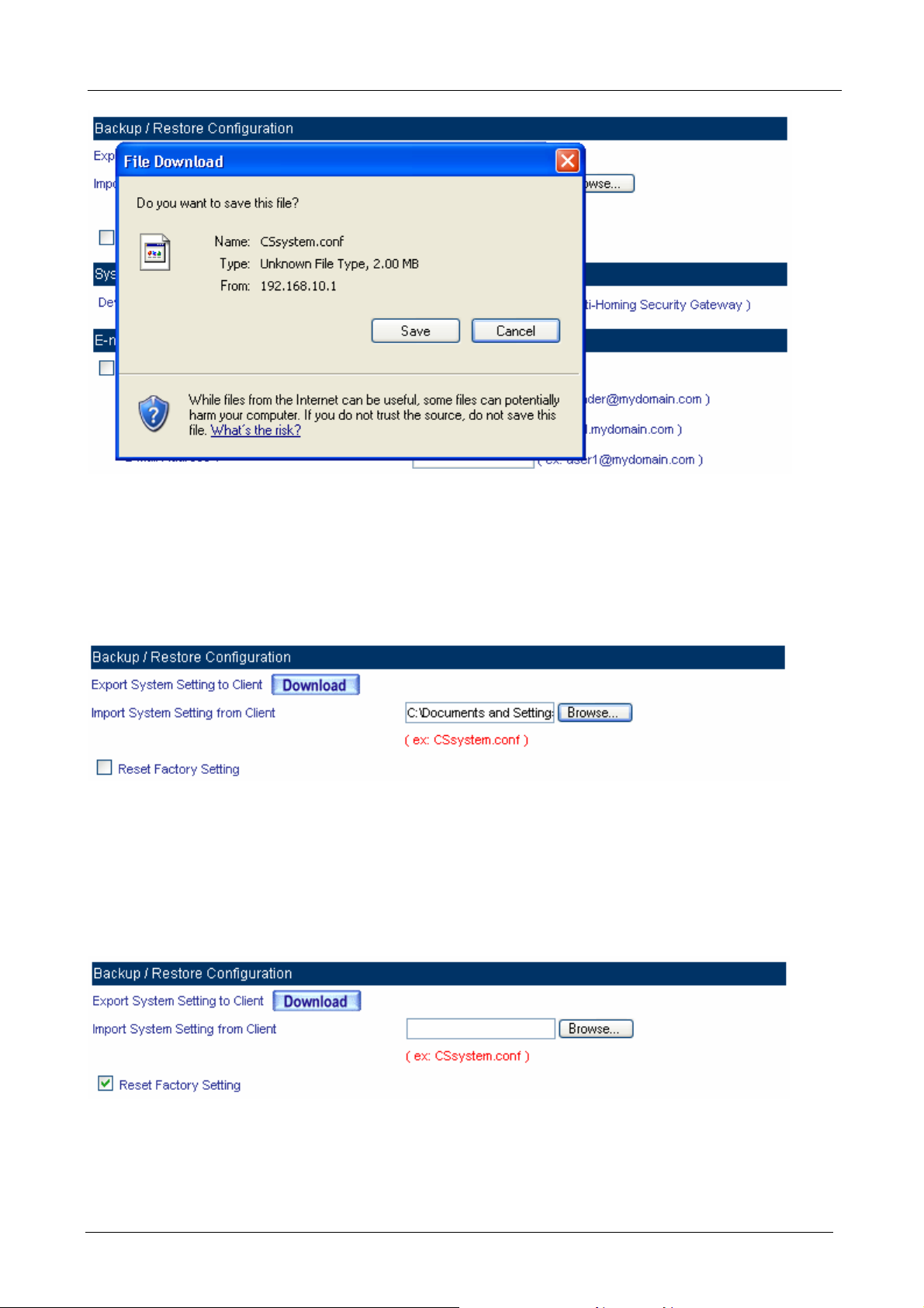
Importing Multi-Homing Security Gateway settings
Multi-Homing Security Gateway User’s Manual
Under Backup/Restore Configuration, click on the Browse button next to Import System Settings from
Client. When the Choose File pop-up window appears, select the file which contains the saved Multi-Homing
Security Gateway Settings, then click OK.
Click OK to import the file into the Multi-Homing Security Gateway or click Cancel to cancel importing.
Restoring Factory Default Settings
Step 1. Select Reset Factory Settings under Backup/Restore Configuration.
Step 2. Click OK at the bottom-right of the screen to restore the factory settings.
System Name Setting
Input the name you want into Device Name column to be the device name.
- 17 -
Page 24

Multi-Homing Security Gateway User’s Manual
Email Setting
Step 1. Select Enable E-mail Alert Notification under E-Mail Setting. This function will enable the
Multi-Homing Security Gateway to send e-mail alerts to the System Administrator when the
network is being attacked by hackers or when emergency conditions occur.
Step 2. SMTP Server IP: Enter SMTP server’s IP address.
Step 3. E-Mail Address 1: Enter the first e-mail address to receive the alarm notification.
Step 4. E-Mail Address 2: Enter the second e-mail address to receive the alarm notification. (Optional)
Click OK on the bottom-right of the screen to enable E-mail alert notification.
Web Management (WAN Interface)
The administrator can change the port number used by HTTP port anytime. (Remote UI Management)
Step 1. Set Web Management (WAN Interface). The administrator can change the port number used
by HTTP port anytime.
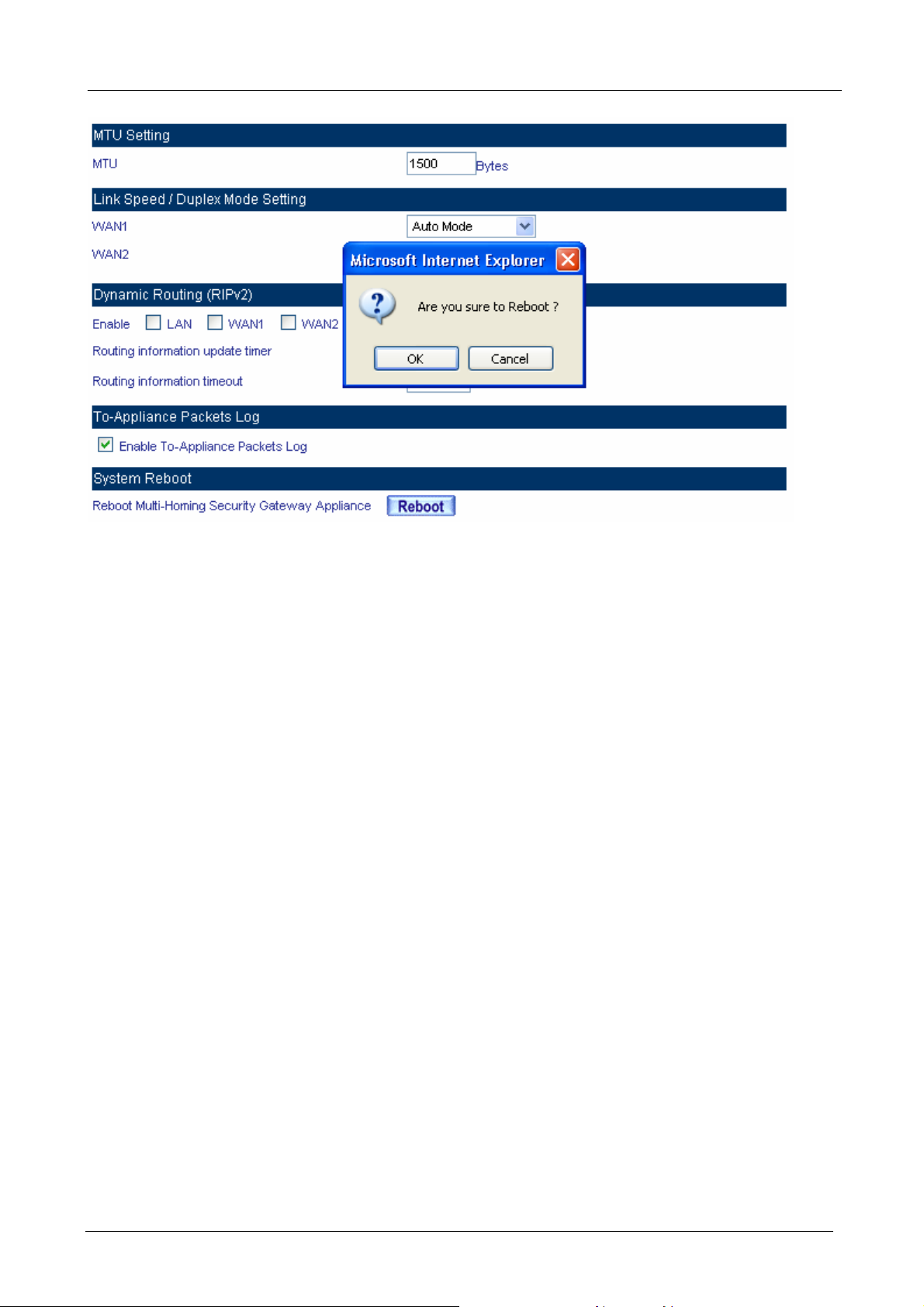
MTU (set networking packet length)
The administrator can modify the networking packet length.
Step 1. MTU Setting. Modify the networking packet length.
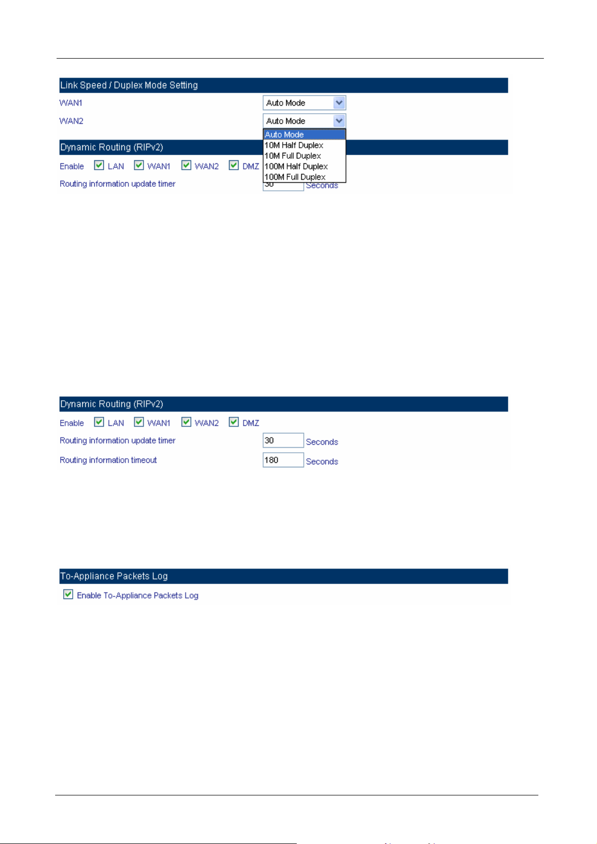
Link Speed / Duplex Mode Setting
This function allows administrator to set the transmission speed and mode of WAN Port.
- 18 -
Page 25
Multi-Homing Security Gateway User’s Manual
Dynamic Routing (RIPv2)
Enable Dynamic Routing (RIPv2), CS-1000 will advertise an IP address pool to the specific network so that
the address pool can be provided to the network. You can choose to enable LAN, WAN or DMZ interface to
allow RIP protocol supporting.
Routing information update timer: CS-1000 will send out the RIP protocol in a period of time to update the
routing table, the default timer is 30 seconds.
Routing information timeout: If CS-1000 does not receive the RIP protocol from the other router in a period
of time, it will cut off the routing automatically until it receives RIP protocol again. The default timer is 180
seconds.
To-Appliance Packet Logging
When the function is selected, the CS-1000 will record the packets that contain the IP address of CS-1000 in
source or destination, the records will display in Traffic Log for administrator to inquire about.
System Reboot
Once this function is enabled, the Multi-Homing Security Gateway will be rebooted.
Reboot Appliance: Click Reboot.
A confirmation pop-up box will appear. Follow the confirmation pop-up box, click OK to restart Multi-Homing
Security Gateway or click Cancel to discard changes.
- 19 -
Page 26
Multi-Homing Security Gateway User’s Manual
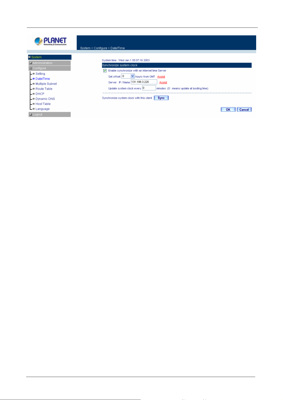
3.1.5 Date/Time
Synchronizing the Multi-Homing Security Gateway with the System Clock
Administrator can configure the Multi-Homing Security Gateway’s date and time by either syncing to an
Internet Network Time Server (NTP) or by syncing to your computer’s clock.
Follow these steps to sync to an Internet Ti me Server
Step 1. Enable synchronization by checking the box.
Step 2. Click the down arrow to select the offset time from GMT.
Step 3. Enter the Server IP Address or Server name with which you want to synchronize.
Step 4. Update system clock every □ minutes You can set the interval time to synchronize with
outside servers. If you set it to 0, it means the device will not synchronize automatically.
Follow this step to sync to your computer’s clock.
Step 1. Click on the Sync button.
Click OK to apply the setting or click Cancel to discard changes.
- 20 -
Page 27
Multi-Homing Security Gateway User’s Manual
ÍÍ
3.1.6 Multiple Subnet
NA T mode
Multiple Subnet allows local port to set multiple subnet works and connect with the Internet through WAN IP
Addresses.
For instance, the lease line of a company applies several real IP Addresses 168.85.88.0/24, and the company
is divided into R&D department, service, sales department, procurement department, accounting department,
the company can distinguish each department by different subnet works for the purpose of convenient
management. The settings are as the following:
1. R&D department sub-network: 192.168.1.11/24 (LAN) ÅÆ 168.85.88.253 (WAN)
2. Service department sub-network: 192.168.2.11/24 (LAN) ÅÆ 168.85.88.252 (WAN)
3. Sales department sub-network: 192.168.3.11/24 (LAN) ÅÆ 168.85.88.251 (WAN)
4. Procurement department sub-network: 192.168.4.11/24 (LAN) ÅÆ 168.85.88.250(WAN)
5. Accounting department sub-network: 192.168.5.11/24 (LAN) ÅÆ 168.85.88.249 (WAN)
The first department (R&D department) was set while setting interface IP, the other four ones have to be
added in Multiple Subnet, after completing the settings, each department use the different WAN IP address to
connect to the internet. The settings of LAN computers on Service department are as the following:
Service IP Address: 192.168.2.1
Subnet Mask: 255.255.255.0
Default Gateway: 192.168.2.11
The other departments are also set by groups, this is the function of Multiple Subnet.
Multiple Subnet settings
Click System on the left side menu bar, select Configure then click Multiple Subnet to enter Multiple Subnet
window.
- 21 -
Page 28
Multi-Homing Security Gateway User’s Manual
ÍÍ
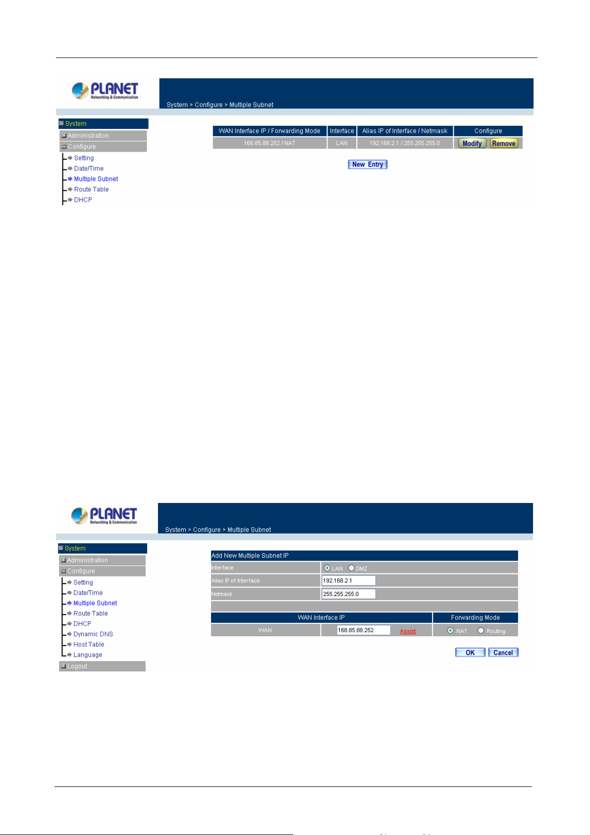
Multiple Subnet functions
WAN Interface IP / Forwarding Mode: Display WAN Port IP address and Forwarding Mode.
Interface: Indicate the multiple subnet location in LAN or DMZ site.
Alias IP of Interface / Netmask: Local port IP address and subnet Mask.
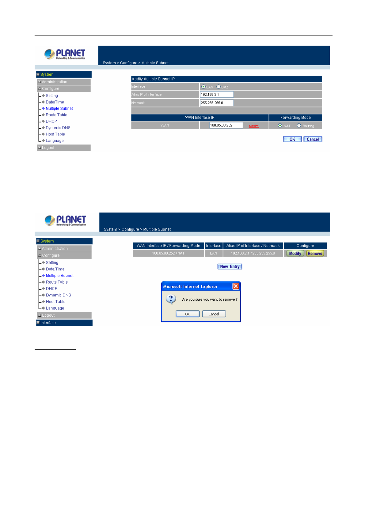
Configure: Modify the settings of Multiple Subnet. Click Modify to modify the parameters of Multiple Subnet
or click Delete to delete settings.
Add a Multiple Subnet NAT Mode.
Step 1: Click the New Entry button below to add Multiple Subnet.
Step 2: Enter the IP address in the website name column of the new window.
Alias IP of Interface: Enter Local port IP address.
Netmask: Enter Local port subnet Mask.
WAN Interface IP: Add WAN IP.
Forwarding Mode: Click the NAT button below to setup.
Step 3: Click OK to add Multiple Subnet or click Cancel to discard changes.
Modify a Multiple Subnet
Step 1: Find the IP address you want to modify and click Modify.
Step 2: Enter the new IP address in Modify Multiple Subnet window.
Step 3: Click the OK button below to change the setting or click Cancel to discard changes.
- 22 -
Page 29
Multi-Homing Security Gateway User’s Manual
Removing a Multiple Subnet
Step 1: Find the IP address you want to delete and click Delete.
Step 2: A confirmation pop-up box will appear, click OK to delete the setting or click Cancel to discard
changes.
Routing Mode
Multiple Subnet allows local port to set Multiple Subnet Routing Mode and connect with the Internet through
WAN IP address.
For example, the leased line of a company applies several real IP Addresses 168.85.88.0/24 and the
company is divided into R&D, Customer Service, Sales, Procurement, and Accounting Department. The
company can distinguish each department by different sub-network for the purpose of convenient
management.
The settings are as the following:
R&D: Alias IP of LAN interface - 168.85.88.1, Netmask: 255.255.255.192
Sales: Alias IP of LAN interface - 168.85.88.65, Netmask: 255.255.255.192
Procurement: Alias IP of LAN interface - 168.85.88.129, Netmask: 255.255.255.192
Accounting: Alias IP of LAN interface - 168.85.88.193, Netmask: 255.255.255.192
- 23 -
Page 30
Multi-Homing Security Gateway User’s Manual
Click System on the left side menu bar, then click Multiple Subnet below Configure menu. Enter Multiple
Subnet window.
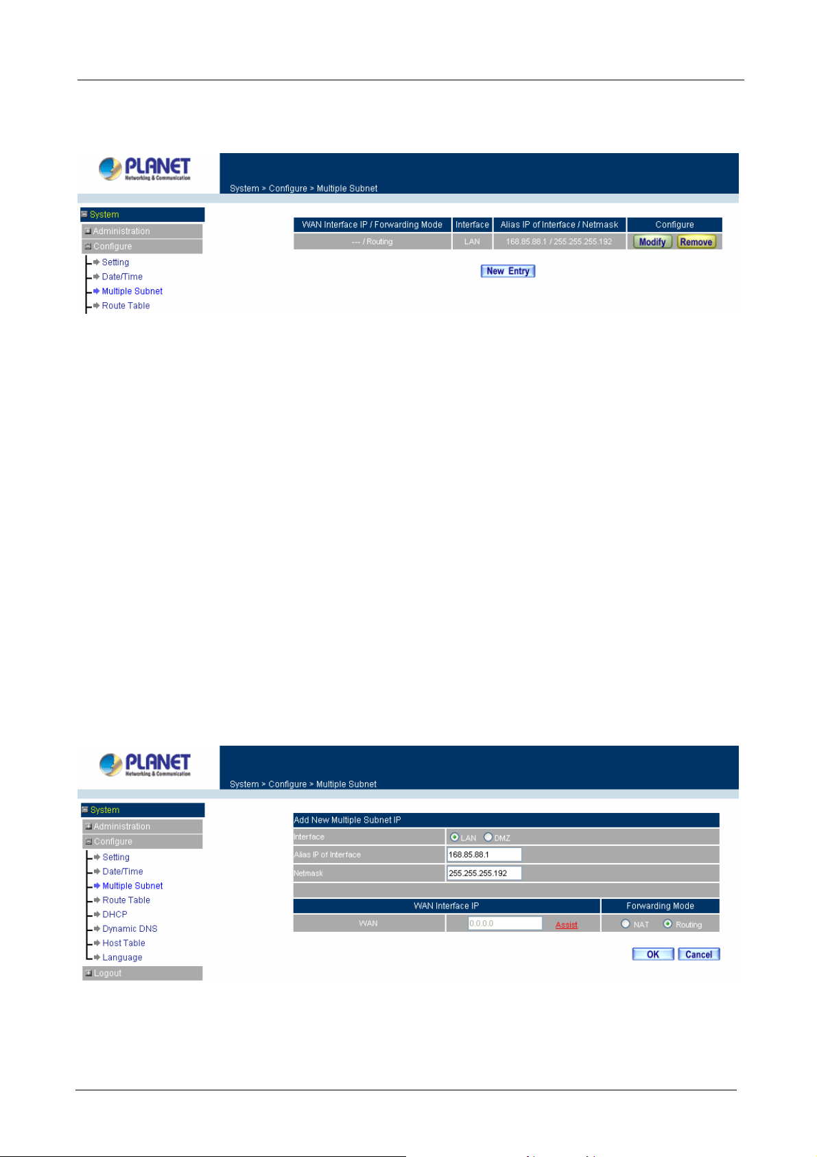
Multiple Subnet functions
WAN Interface IP / Forwarding Mode: Display WAN Port IP address and Forwarding Mode which is NAT
Mode or Routing Mode.
Interface: Indicate the multiple subnet location in LAN or DMZ site.
Alias IP of Interface / Netmask: Local port IP address and subnet Mask.
Configure: Modify the settings of Multiple Subnet. Click Modify to modify the parameters of Multiple Subnet
or click Delete to delete settings.
Adding a Multiple Subnet Routing Mode
Step 1: Click the Add button below to add Multiple Subnet.
Step 2: Enter the IP address in Add Multiple Subnet window.
Alias IP of Interface: Enter Local port IP Address.
Netmask: Enter Local port subnet Mask.
WAN Interface IP: Add WAN IP
Forwarding Mode: Click the Routing button below to setup.
Step 3: Click OK to add Multiple Subnet or click Cancel to discard changes.
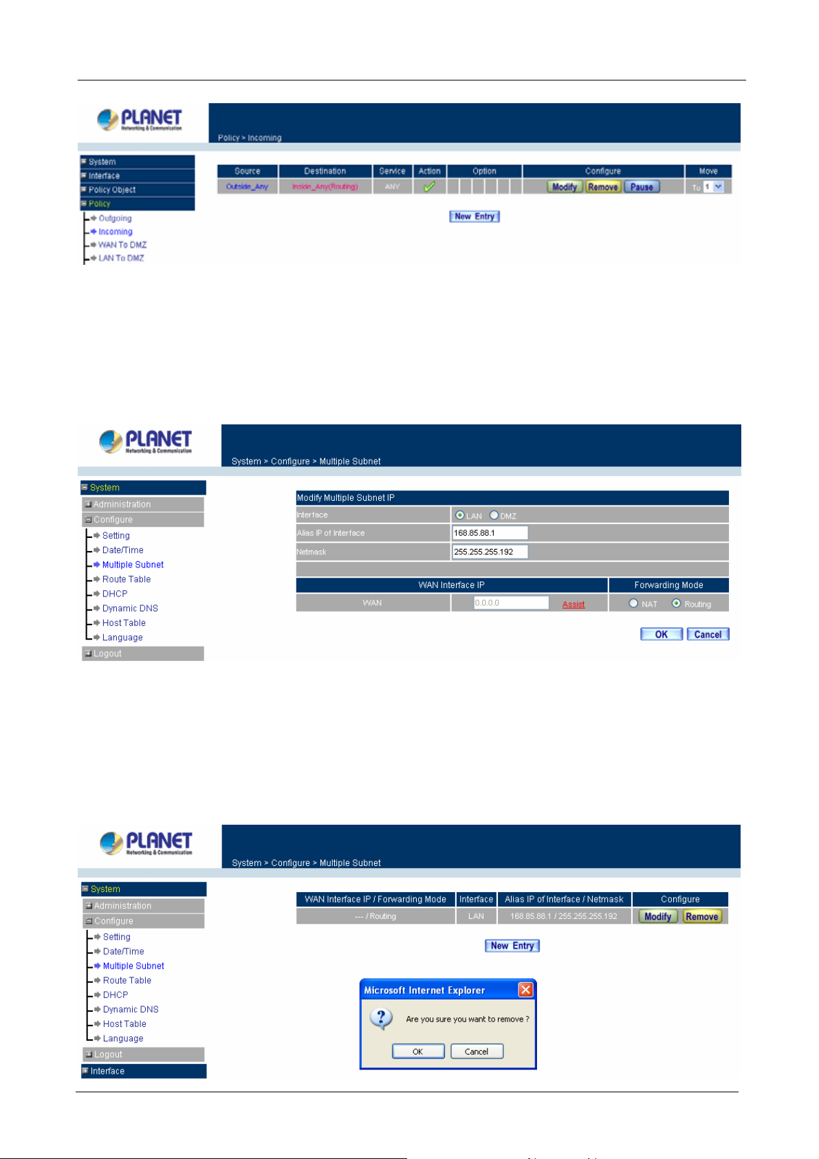
Step 4: Adding a new WAN to LAN Policy. In the Incoming window, click the New Entry button.
- 24 -
Page 31
Multi-Homing Security Gateway User’s Manual
Modify a Multiple Subnet Routing Mode
Step 1: Find the IP address you want to modify in Multiple Subnet menu, then click Modify button, on the right
side of the service providers, click OK.
Step 2: Enter the new IP address in Modify Multiple Subnet window.
Step 3: Click the OK button below to change the setting or click Cancel to discard changes.
Removing a Multiple Subnet Routing Mode
Step 1: Find the IP Address you want to delete in Multiple Subnet menu, then click Delete button, on the right
side of the service providers, click OK.
Step 2: A confirmation pop-up box will appear, click OK to delete the setting or click Cancel to discard
changes.
- 25 -
Page 32

Multi-Homing Security Gateway User’s Manual
3.1.7 Route Table
In this section, the Administrator can add static routes for the networks.
Entering the Route Table screen
Step 1. Click System on the left hand side menu bar, then click Route Table below the Configure
menu. The Route Table window appears, in which current route settings are shown.
ÍÍ
Route Table functions
Interface: Destination network, LAN or WAN networks.
Destination IP / Netmask: IP address and subnet mask of destination network.
Gateway: Gateway IP address for connecting to destination network.
Configure: Change settings in the route table.
Adding a new Static Route
Step 1. In the Route Table window, click the New Entry button.
Step 2. In the Add New Static Route window, enter new static route information.
Step 3. In the Interface field’s pull-down menu, choose the network to connect (LAN, WAN, DMZ).
Step 4. Click OK to add the new static route or click Cancel to cancel.
Modifying a Static Route:
Step 1. In the Route Table menu, find the route to edit and click the corresponding Modify option in the
- 26 -
Page 33

Multi-Homing Security Gateway User’s Manual
Configure field.
Step 2. In the Modify Static Route window, modify the necessary routing addresses.
Step 3. Click OK to apply changes or click Cancel to cancel it.
Removing a Static Route
Step 1. In the Route Table window, find the route to remove and click the corresponding Remove option
in the Configure field.
Step 2. In the Remove confirmation pop-up box, click OK to confirm removing or click Cancel to cancel
it.
3.1.8 DHCP
In the section, the Administrator can configure DHCP (Dynamic Host Configuration Protocol) settings for the
LAN network.
Entering the DHCP window
Click System on the left hand side menu bar, then to click DHCP below the Configure menu. The DHCP
window appears in which current DHCP settings are shown on the screen.
- 27 -
Page 34

ÍÍ
Multi-Homing Security Gateway User’s Manual
Dynamic IP Address functions
Subnet: LAN network’s subnet
Netmask: LAN network’s netmask
Gateway: LAN network’s gateway IP address
Broadcast: LAN network’s broadcast IP address
Enabling DHCP Support
Step 1. In the Dynamic IP Address window, click Enable DHCP Support.
Domain Name: The Administrator may enter the name of the LAN network domain if preferred.
Automatically Get DNS: Check this box to automatically detect DNS server.
DNS Server 1: Enter the distributed IP address of DNS Server 1.
DNS Server 2: Enter the distributed IP address of DNS Server 2.
WINS Server 1: Enter the distributed IP address of WINS Server 1.
WINS Server 2: Enter the distributed IP address of WINS Server 2.
LAN interface:
Client IP Address Range 1: Enter the starting and the ending IP address dynamically
assigning to DHCP clients.
Client IP Address Range 2: Enter the starting and the ending IP address dynamically
assigning to DHCP clients. (Optional)
DMZ interface:
- 28 -
Page 35

Multi-Homing Security Gateway User’s Manual
Client IP Address Range 1: Enter the starting and the ending IP address dynamically
assigning to DHCP clients.
Client IP Address Range 2: Enter the starting and the ending IP address dynamically
assigning to DHCP clients. (Optional)
Leased Time: Enter the leased time for DHCP.
Step 2. Click OK to enable DHCP support.
3.1.9 Dynamic DNS
The Dynamic DNS (require Dynamic DNS Service) allows you to alias a dynamic IP address to a static
hostname, allowing your device to be more easily accessed by specific name. When this function is enabled,
the IP address in Dynamic DNS Server will be automatically updated with the new IP address provided by
ISP.
ÍÍ
Click Dynamic DNS in the System menu to enter Dynamic DNS window.
The icons in Dynamic DNS window:
!: Update Status,
Domain name: Enter the password provided by ISP.
WAN IP Address: IP address of the WAN port.
Configure: Modify dynamic DNS settings. Click Modify to change the DNS parameters; click Delete to delete
the settings.
How to use dynamic DNS:
The Multi-Homing Security Gateway provides many service providers, users have to register prior to use this
function. For the usage regulations, see the providers’ websites.
How to register:
Firstly, Click Dynamic DNS in the System menu to enter Dynamic DNS window, then click Add button on the
Connecting; Update succeed; Update fail; Unidentified error.
right side of the service providers, click Sign up, the service providers’ website will appear, please refer to the
website for the way of registration.
- 29 -
Page 36
Multi-Homing Security Gateway User’s Manual
Click to link to the website selected on the left.
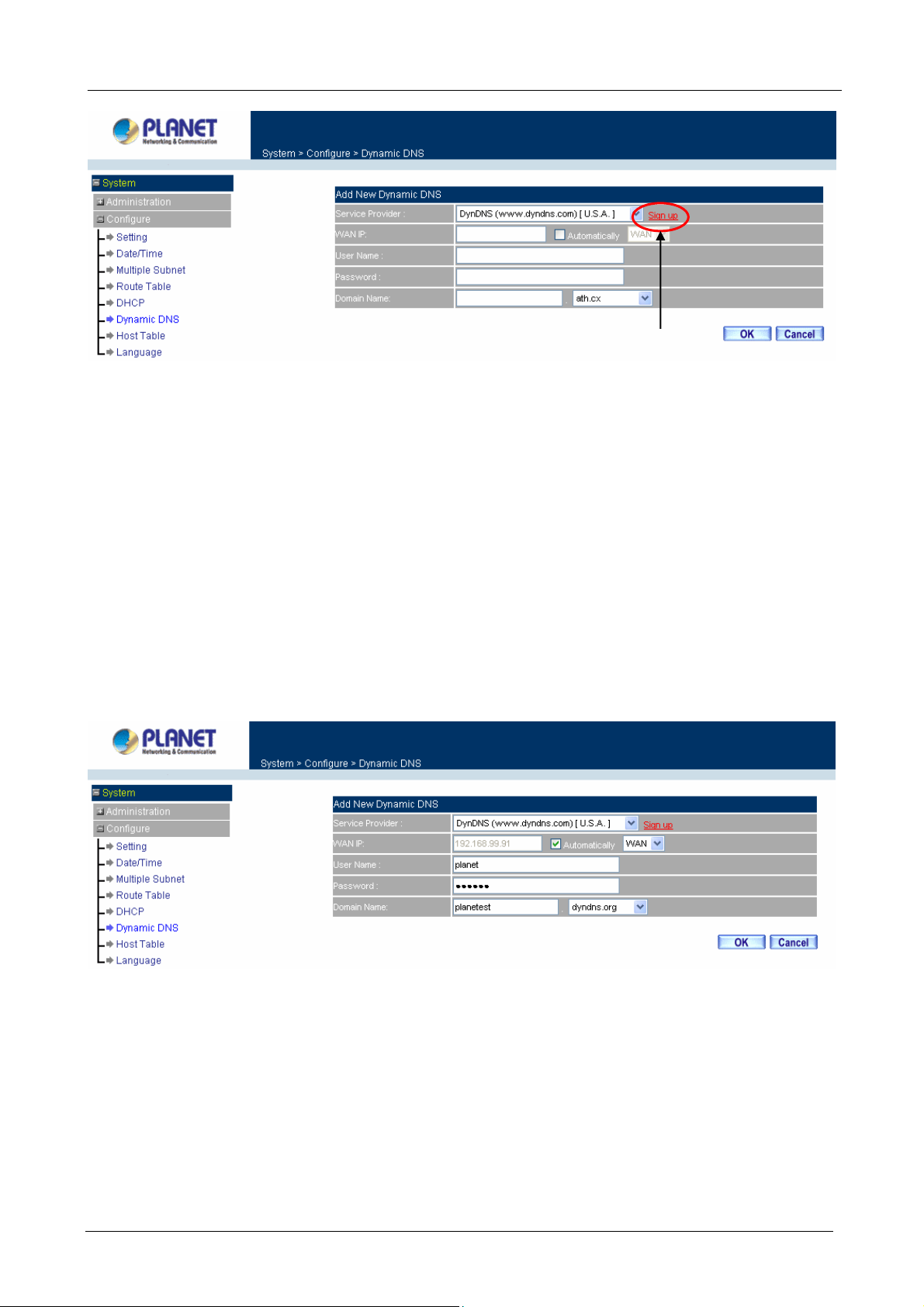
Add Dynamic DNS settings
Step 1. Click Add button.
Step 2. Click the information in the column of the new window.
Service providers: Select service providers.
Sign up: to the service providers’ website.
WAN IP Address: IP Address of the WAN port.
Automatically : Check to automatically fill in the WAN IP.。
User Name: Enter the registered user name.
Password: Enter the password provided by ISP (Internet Service Provider).
Domain name: Your host domain name provided by ISP.
Click OK to add dynamic DNS or click Cancel to discard changes.
Modify dynamic DNS
Step 1. Find the item you want to change and click Modify.
Step 2. Enter the new information in the Modify Dynamic DNS window.
Click OK to change the settings or click Cancel to discard changes.
- 30 -
Page 37

Multi-Homing Security Gateway User’s Manual
Remove Dynamic DNS
Step 1. Find the item you want to change and click Remove.
Step 2. A confirmation pop-up box will appear, click OK to delete the settings or click Cancel to discard
changes.
3.1.10 Host Table
The Multi-Homing Security Gateway’s Administrator may use the Host Table function to make the
Multi-Homing Security Gateway act as a DNS Server for the LAN and DMZ network. All DNS requests to a
specific Domain Name will be routed to the Multi-Homing Security Gateway’s IP address. For example, let’s
say an organization has their mail server (i.e., mail.planet.com.tw) in the DMZ network (i.e. 192.168.10.10).
The outside Internet world may access the mail server of the organization easily by its domain name,
providing that the Administrator has set up Virtual Server or Mapped IP settings correctly. However, for the
users in the LAN network, their WAN DNS server will assign them a public IP address for the mail server. So
for the LAN network to access the mail server (mail.planet.com.tw), they would have to go out to the Internet,
then to come back through the Multi-Homing Security Gateway to access the mail server. Essentially, the LAN
network is accessing the mail server by a real public IP address, while the mail server serves their request by
a NAT address and not a real one.
- 31 -
Page 38
Multi-Homing Security Gateway User’s Manual
This odd situation occurs when there are servers in the DMZ network and they are bound to real IP addresses.
To avoid this, set up Host Table so all the LAN network computers will use the Multi-Homing Security
Gateway as a DNS server, which acts as the DNS proxy.
If you want to use the Host Table function of the device, the end user’s main DNS server IP address
should be the same IP Address as the device.
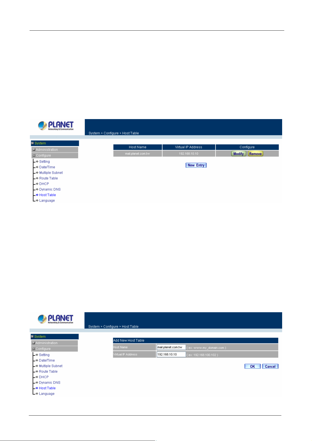
Click on System in the menu bar, then to click on Host Table below the Configure menu. The Host Table
window will appear.
ÍÍ
Below is the information needed for setting up the Host Table:
• Host Name: The domain name of the server
• Virtual IP Address: The virtual IP address respective to Host Table
• Configure: modify or remove each Host Table policy
Adding a new Host Table
Step 1: Click on the New Entry button and the Add New Host Table window will appear.
Step 2: Fill in the appropriate settings for the domain name and virtual IP address.
Step 3: Click OK to save the policy or Cancel to cancel.
- 32 -
Page 39

Multi-Homing Security Gateway User’s Manual
Modifying a Host Table
Step 1: In the Host Table window, find the policy to be modified and click the corresponding Modify option
in the Configure field.
Step 2: Make the necessary changes needed.
Step 3: Click OK to save changes or click on Cancel to cancel modifications.
Removing a Host Table
Step 1: In the Host Table window, find the policy to be removed and click the corresponding Remove
option in the Configure field.
Step 2: A confirmation pop-up box will appear, click OK to remove the Host Table or click Cancel.
3.1.11 Language
Administrator can configure the Multi-Homing Security Gateway to select the Language version.
Step 1. Select the Language version (English Version, Traditional Chinese Version or Simplified
Chinese Ver sion).
Step 2. Click [OK] to set the Language version or click Cancel to discard changes.
- 33 -
Page 40

Multi-Homing Security Gateway User’s Manual
3.1.12 Logout
Step 1. Select this option to the device’s Logout the Multi-Homing Security Gateway. This function
protects your system while you are away.
Step 2. Click Logout the Multi-Homing Security Gateway.
Step 3. Click OK to logout or click Cancel to discard the change.
ÍÍ
3.2 Interface
In this section, the Administrator can set up the IP addresses for the office network. The Administrator may
configure the IP addresses of the LAN network, the WAN network, and the DMZ network. The netmask and
gateway IP addresses are also configured in this section.
3.2.1 LAN
Entering the Interface menu:
Click on Interface in the left menu bar. Then click on LAN below it. The current settings of the interface
addresses will appear on the screen.
- 34 -
Page 41

Multi-Homing Security Gateway User’s Manual
Configuring the Interface Settings
Using the LAN Interface, the Administrator sets up the LAN network. The LAN network will use a private IP
scheme. The private IP network will not be routable on the Internet.
IP Address: The private IP address of the Multi-Homing Security Gateway’s LAN network is the IP address of
the LAN port of the device. The default IP address is 192.168.1.1. If the new LAN IP Address is not
192.168.1.1, the Administrator needs to set the IP Address on the computer to be the same subnet as the
Multi-Homing Security Gateway and restart the System to make the new IP address effective. For example, if
the Multi-Homing Security Gateway’s new LAN IP Address is 172.16.0.1, then enter the new LAN IP Address
172.16.0.1 in the URL field of browser to connect to Multi-Homing Security Gateway.
NetMask: This is the subnet mask of the LAN network. The default netmask of the device is 255.255.255.0.
Ping: Select this to allow the LAN network to ping the IP Address of the Multi-Homing Security Gateway. If set
to enable, the device will respond to ping packets from the LAN network.
HTTP: Select this to allow the device WEBUI to be accessed from the LAN network.
3.2.2 WAN
Entering the Interface menu
Click on Interface in the left menu bar. Then click on WAN below it. The current settings of the interface
addresses will appear on the screen.
Balance Mode:
Auto: CS-1000 distributes the WAN 1/2 download by proportion automatically according to the WAN
download bandwidth. (For users who are using various download bandwidth)
Round-Robin: CS-1000 distributes the WAN 1/2 download bandwidth 1:1, in other words, it selects the
agent by order. (For users who are using same download bandwidths)
By Traffic: CS-1000 distributes the WAN 1/2 download bandwidth by traffic. (For users who are
connected to the Internet via a fixed WAN IP address)
By Session: CS-1000 distributes the WAN 1/2 download bandwidth by session. (For users who are
connected to the Internet via a fixed WAN IP address)
By Packet: CS-1000 distributes the WAN 1/2 download bandwidth by packet and saturated connection.
(For users who are connected to the Internet via a fixed WAN IP address)
- 35 -
Page 42

Multi-Homing Security Gateway User’s Manual
WAN No: WAN port 1 or 2.
Connect Mode: Display the current connection mode: PPPoE, Dynamic IP Address (Cable Modem User) or
Static IP Address.
IP Address: Display the current WAN IP Address.
Saturated Connections: Set the number for saturation whenever session numbers reach it, the CS-1000
switches to the next WAN port on the list. This function is only applicable for By Session mode.
Ping / HTTP: Display Ping/HTTP functions of WAN 1/2 to show if they are enabled or disabled.
Configure: Click Modify to modify WAN 1/2 settings.
Priority: Set priority of WAN 1/2 for Internet Access.
WAN 1/2 Interfac e
Using the WAN 1/2 Interface, the Administrator can sets up the WAN 1/2 network. These IP addresses are
real public IP Addresses, and are routable on the Internet.
Alive Indicator Site IP: This feature is used to ping an address for detecting WAN connection status.
Service: ICMP You can select an IP address by Assist, or type an IP address manually.
Service: DNS You can select a DNS IP and Domain name by Assist, or type the related data manually.
PPPoE (ADSL User): This option is for PPPoE users who are required to enter a username and password in
order to connect.
Username: Enter the PPPoE username provided by the ISP.
Password: Enter the PPPoE password provided by the ISP.
IP Address provided by ISP:
Dynamic: Select this if the IP address is automatically assigned by the ISP.
Fixed: Select this if you were given a static IP address. Enter the IP address that is given to you by
your ISP.
Max. Upstream/Downstream Bandwidth: The bandwidth provided by ISP.
Auto Disconnect: The PPPoE connection will automatically disconnect after a length of idle time (no
activities). Enter in the amount of idle minutes before disconnection. Enter ‘0’ if you do not want the
PPPoE connection to disconnect at all.
Ping: Select this to allow the WAN 1 network to ping the IP Address of the Multi-Homing Security
Gateway. This will allow people from the Internet to be able to ping the Multi-Homing Security Gateway. If
it sets to enable, the device will respond to echo request packets from the WAN 1/2 network.
HTTP: Select this to allow the device WEBUI to be accessed from the WAN 1 network. This will allow
WebUI to be configured from a user on the Internet. Keep in mind that the device always requires a
username and password to enter the WebUI.
- 36 -
Page 43

Multi-Homing Security Gateway User’s Manual
For Dynamic IP Address (Cable Mod em User): This option is for users who are automatically assigned an
IP address by their ISP, such as cable modem users. The following fields apply:
IP Address: The dynamic IP address obtained by CS-1000 from the ISP will be displayed here. This is
the IP address of the WAN 1 (WAN 2) port of the device.
MAC Address: This is the MAC Address of the device. Some ISPs require specified MAC address. If the
required MAC address is your PC’s, click Clone MAC Address.
Hostname: This will be the name assign to the device. Some cable modem ISP assign a specific
hostname in order to connect to their network. Please enter the hostname here. If not required by your
ISP, you do not have to enter a hostname.
Domain Name: You can specify your own domain name or leave it blank.
User Name: The user name is provided by ISP.
Password: The password is provided by ISP.
Max. Upstream/Downstream Bandwidth: The bandwidth provided by ISP.
Ping: Select this to allow the WAN 1 network to ping the IP Address of the Multi-Homing Security
Gateway. This will allow people from the Internet to be able to ping the Multi-Homing Security Gateway. If
it sets to enable, the device will respond to echo request packets from the WAN 1/2 network.
HTTP: Select this to allow the device WEBUI to be accessed from the WAN 1 network. This will allow
WebUI to be configured from a user on the Internet. Keep in mind that the device always requires a
username and password to enter the WebUI.
- 37 -
Page 44

Multi-Homing Security Gateway User’s Manual
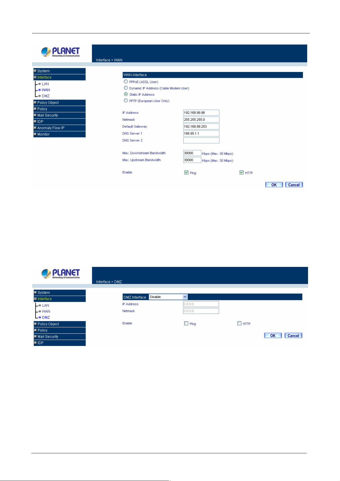
For Static IP Address: This option is for users who are assigned a static IP Address from their ISP. Your ISP
will provide all the information needed for this section such as IP Address, Netmask, Gateway, and DNS. Use
this option also if you have more than one public IP Address assigned to you.
IP Address: Enter the static IP address assigned to you by your ISP. This will be the public IP address of
the WAN 1 port of the device.
Netmask: This will be the Netmask of the WAN 1 network. (i.e. 255.255.255.0)
Default Gateway: This will be the Gateway IP address.
Domain Name Server (DNS): This is the IP Address of the DNS server.
Max. Upstream/Downstream Bandwidth: The bandwidth provided by ISP.
Ping: Select this to allow the WAN 1 network to ping the IP Address of the Multi-Homing Security
Gateway. This will allow people from the Internet to be able to ping the Multi-Homing Security Gateway.
If it sets to enable, the device will respond to echo request packets from the WAN 1/2 network.
HTTP: Select this to allow the device WEBUI to be accessed from the WAN 1 network. This will allow
WebUI to be configured from a user on the Internet. Keep in mind that the device always requires a
username and password to enter the WebUI.
- 38 -
Page 45
Multi-Homing Security Gateway User’s Manual
3.2.3 DMZ
The Administrator uses the DMZ Interface to set up the DMZ network. The DMZ network consists of server
computers such as FTP, SMTP, and HTTP (web). These server computers are put in the DMZ network so they
can be isolated from the LAN (LAN) network traffic. Broadcast messages from the LAN network will not cross
over to the DMZ network to cause congestions and slow down these servers. This allows the server computers
to work efficiently without any slowdowns.
DMZ Interface: Display NAT Mode or TRANSPARENT Mode functions of DMZ to show if they are enabled or
disabled.
IP Address: The private IP address of the Multi-Homing Security Gateway’s DMZ interface. This will be the IP
address of the DMZ port. If it is in NAT mode, the IP address will be a private one and cannot use the same
network as the WAN or LAN subnet.
NetMask: This will be the subnet mask of the DMZ network.
Ping: Select this to allow the DMZ network to ping the IP Address of the Multi-Homing Security Gateway. This
will allow people from the Internet to be able to ping the Multi-Homing Security Gateway. If set to enable, the
device will respond to echo request packets from the DMZ network.
HTTP: Select this to allow the device WebUI to be accessed from the DMZ network. This will allow the WebUI
- 39 -
Page 46

Multi-Homing Security Gateway User’s Manual
to be configured from a user on the Internet. Keep in mind that the device always requires a username and
password to enter the WebUI.
3.3 Policy Object
The Policy Object is the pre-setting item for Policy editing. The administrator can configure all necessary
items here before he wants to configure Multi-Homing Security Gateway Policy. The contents include
Address, Service, Schedule, QoS, Authentication, Content Blocking, Virtua l serv er and VPN.
3.3.1 Address
The Multi-Homing Security Gateway allows the Administrator to set addresses of the LAN network, LAN
network group, WAN network, WAN group, DMZ network and DMZ group.
What is the Address Table?
An IP address in the Address Table can be an address of a computer or a sub network. The Administrator can
assign an easily recognized name to an IP address. Based on the network it belongs to, an IP address can be
an LAN IP address, WAN IP address and DMZ IP address. If the Administrator needs to create a control
policy for packets of different IP addresses, he can first add a new group in the LAN Network Group or the
WAN Netw ork Group and assign those IP addresses into the newly created group. Using group addresses
can greatly simplify the process of building control policies.
How to use Address Table
With easily recognized names of IP addresses and names of address groups shown in the address table, the
Administrator can use these names as the source address or destination address of control policies. The
address table should be built before creating control policies, so that the Administrator can pick the names of
correct IP addresses from the address table when setting up control policies.
3.3.1.1 LAN
Entering the LAN window
Step 1. Click LAN under the Address menu to enter the LAN window. The current setting information
such as the name of the LAN network, IP and Netmask addresses will show on the screen.
- 40 -
Page 47
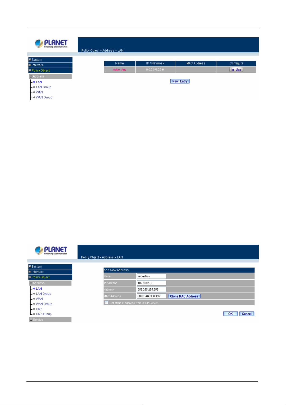
Multi-Homing Security Gateway User’s Manual
ÍÍ
Definition
Name: Name of LAN network address.
IP / Netmask: IP address and subnet mask of LAN network
MAC Address: MAC address corresponded with LAN IP address.
Configure: You can configure the settings in LAN network. Click Modify to change the parameters in LAN
network. Click Remove to delete the settings.
In the LAN window, if one of the members has been added to Policy or LAN Group, the Configure column
will show the message – In Use. In this case, you are not allowed to modify or remove the setting.
Adding a new LAN Address
Step 1. In the LAN window, click the New Entry button.
Step 2. In the Add New Address window, enter the settings of a new LAN network address.
Step 3. Click OK to add the specified LAN network or click Cancel to cancel the changes.
If you want to enable Get Static IP address from DHCP Server function, enter the MAC Address then check
the Get Static IP address from DHCP Server.
Modifying an LAN Address
- 41 -
Page 48

Multi-Homing Security Gateway User’s Manual
Step 1. In the LAN window, locate the name of the network to be modified. Click the Modify option in its
corresponding Configure field. The Modify Address window appears on the screen
immediately.
Step 2. In the Modify Address window, fill in the new address.
Step 3. Click OK to save changes or click Cancel to discard changes.
Removing a LAN Address
Step 1. In the LAN window, locate the name of the network to be removed. Click the Remove option in
its corresponding Configure field.
Step 2. In the Remove confirmation pop-up box, click OK to remove the address or click Cancel to
discard changes.
3.3.1.2 LAN Group
Entering the LAN Group window
The LAN Addresses may be combined together to become a group.
Step 1. Click LAN Group under the Address menu to enter the LAN Group window. The current setting
- 42 -
Page 49
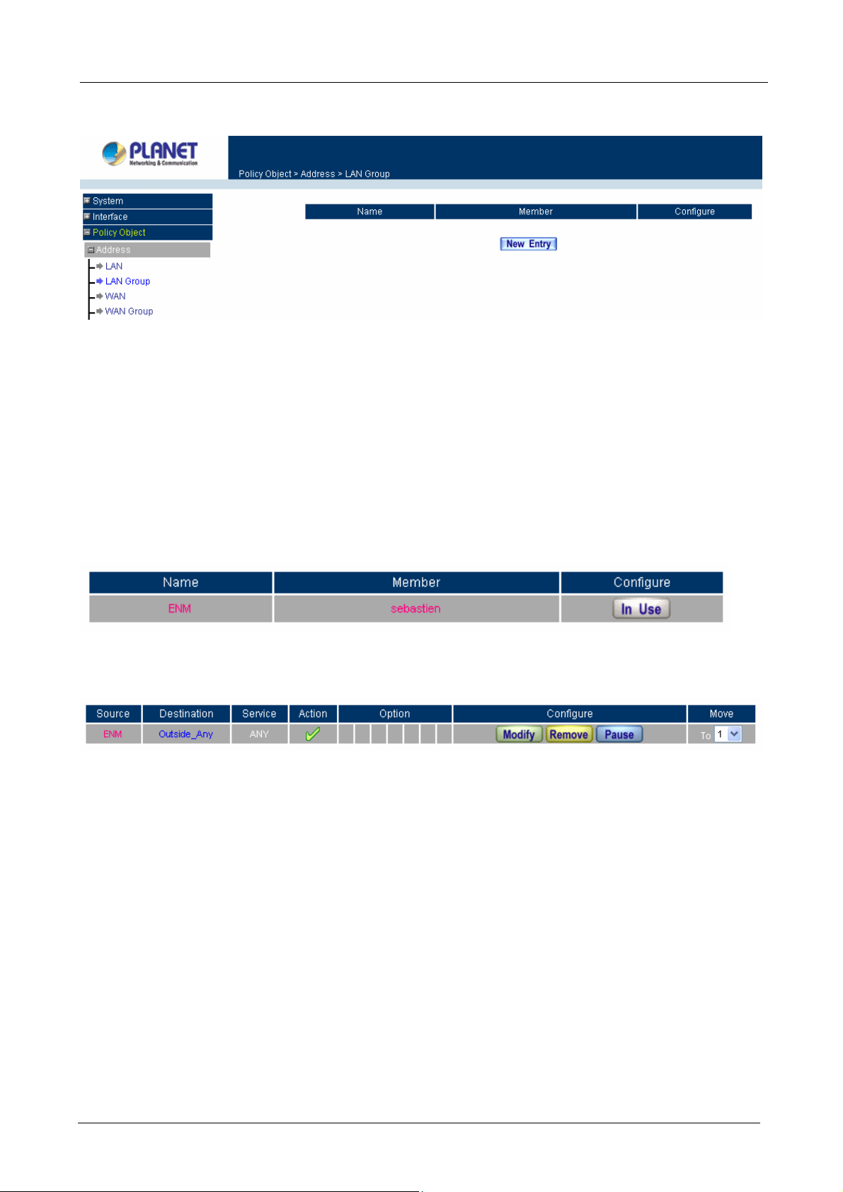
Multi-Homing Security Gateway User’s Manual
information for the LAN network group appears on the screen.
ÍÍ
Definitions
Name: Name of the LAN group.
Member: Members of the group.
Configure: Configure the settings of LAN group. Click Modify to change the settings of LAN group. Click
Remove to delete the group.
In the LAN Group window, if one of the LAN Group has been added to Policy, the Configure column will
show the message – In Use. In this case, you are not allowed to modify or remove the LAN group.
You have to delete or pause the Group in Policy window, and then you are allowed to configure the LAN
Group.
Adding a LAN Group
Step 1. In the LAN Group window, click the New Entry button to enter the Add New Address Group
window.
Step 2. In the Add New Address Group window:
Available address: list the names of all the members of the LAN network.
Selected address: list the names to be assigned to the new group.
Name: enter the name of the new group in the open field.
Step 3. Add members: Select names to be added in Available address list, and click the Add>> button
to add them to the Selected address list.
Step 4. Remove members: Select names to be removed in the Selected Address list, and click the
<<Remove button to remove these members from Selected Address list.
- 43 -
Page 50

Multi-Homing Security Gateway User’s Manual
Step 5. Click OK to add the new group or click Cancel to discard changes.
Modifying a LAN Group
Step 1. In the LAN Group window, locate the network group desired to be modified and click its
corresponding Modify option in the Configure field.
Step 2. A window displaying the information of the selected group appears:
Available address: list names of all members of the LAN network.
Selected address: list names of members which have been assigned to this group.
Step 3. Add members: Select names in Available address list, and click the Add>> button to add
them to the Selected address list.
Step 4. Remove members: Select names in the Selected address list, and click the <<Remove button
to remove these members from the Selected address list.
Click OK to save changes or click Cancel to discard changes.
- 44 -
Page 51

Multi-Homing Security Gateway User’s Manual
Removing a LAN Group
Step 1. In the LAN Group window, locate the group to be removed and click its corresponding Remove
option in the Configure field.
Step 2. In the Remove confirmation pop-up box, click OK to remove the group or click Cancel to
discard changes.
3.3.1.3 WAN
Entering the WAN window
- 45 -
Page 52

Multi-Homing Security Gateway User’s Manual
Step 1. Click WAN under the Address menu to enter the WAN window. The current setting
information, such as the name of the WAN network, IP and Netmask addresses will show on the
screen.
ÍÍ
Definitions
Name: Name of WAN network address.
IP/Netmask: IP address/Netmask of WAN network.
Configure: Configure the settings of WAN network. Click Modify to change the settings of WAN network.
Click Remove to delete the setting of WAN network.
NOTE: In the WAN window, if one of the members has been added to Policy or WAN Group, the Configure
column will show the message – In Use. In this case you are not allowed to modify or remove the settings.
Adding a new WAN Address
Step 1. In the WAN window, click the New Entry button.
Step 2. In the Add New Address window, enter the settings for a new WAN network address.
Step 3. Click OK to add the specified WAN network or click Cancel to discard changes.
Modifying an WAN Address
Step 1. In the WAN table, locate the name of the network to be modified and click the Modify option in
its corresponding Configure field.
- 46 -
Page 53

Multi-Homing Security Gateway User’s Manual
Step 2. The Modify Address window will appear on the screen immediately. In the Modify Address
window, fill in new address.
Step 3. Click OK to save changes or click Cancel to discard changes.
Removing an WAN Address
Step 1. In the WAN table, locate the name of the network to be removed and click the Remove option in
its corresponding Configure field.
Step 2. In the Remove confirmation pop-up box, click OK to remove the address or click Cancel to
discard changes.
3.3.1.4 WAN Group
Entering the WAN Group window
Step 1. Click the WAN Group under the Address menu bar to enter the WAN window. The current
- 47 -
Page 54
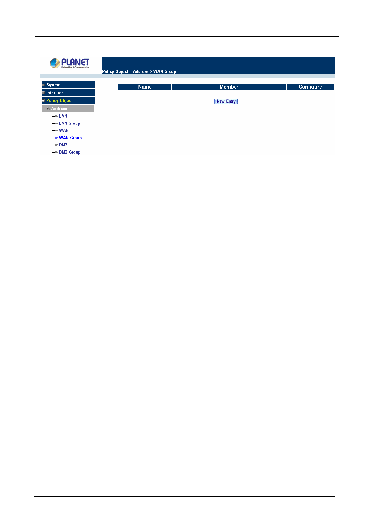
Multi-Homing Security Gateway User’s Manual
settings for the WAN network group(s) will appear on the screen.
ÍÍ
Definitions:
Name: Name of the WAN group.
Member: Members of the group.
Configure: Configure the settings of WAN group. Click Modify to change the parameters of WAN group.
Click Remove to delete the selected group.
NOTE: In the WAN Group window, if one of the members has been added to the Policy, “In Use” message
will appear in the Configure column. You are not allowed to modify or remove the settings. Go to the Policy
window to remove the setting, and then you can configure.
Adding an WAN Group
Step 1. In the WAN Group window, click the New Entry button and the Add New Address Group
window will appear.
Step 2. In the Add New Address Group window the following fields will appear:
Name: enter the name of the new group.
Available address: List the names of all the members of the WAN network.
Selected address: List the names to assign to the new group.
Add members: Select the names to be added in the Available address list, and click the
Add>> button to add them to the Selected address list.
Remove members: Select the names to be removed in the Selected address list, and click
the <<Remove button to remove them from the Selected address list.
Step 3. Click OK to add the new group or click Cancel to discard changes.
- 48 -
Page 55

Multi-Homing Security Gateway User’s Manual
Modifying a WAN Gr oup
Step 1. In the WAN Group window, locate the network group to be modified and click its corresponding
Modify button in the Configure field.
Step 2. A window displaying the information of the selected group appears:
Available address: list the names of all the members of the WAN network.
Selected address: list the names of the members that have been assigned to this group.
Step 3. Add members: Select the names to be added in the Available address list, and click the
Add>> button to add them to the Selected address list.
Step 4. Remove members: Select the names to be removed in the Selected address list, and click the
<<Remove button to remove them from the Selected address list.
Step 5. Click OK to save changes or click Cancel to discard changes.
- 49 -
Page 56
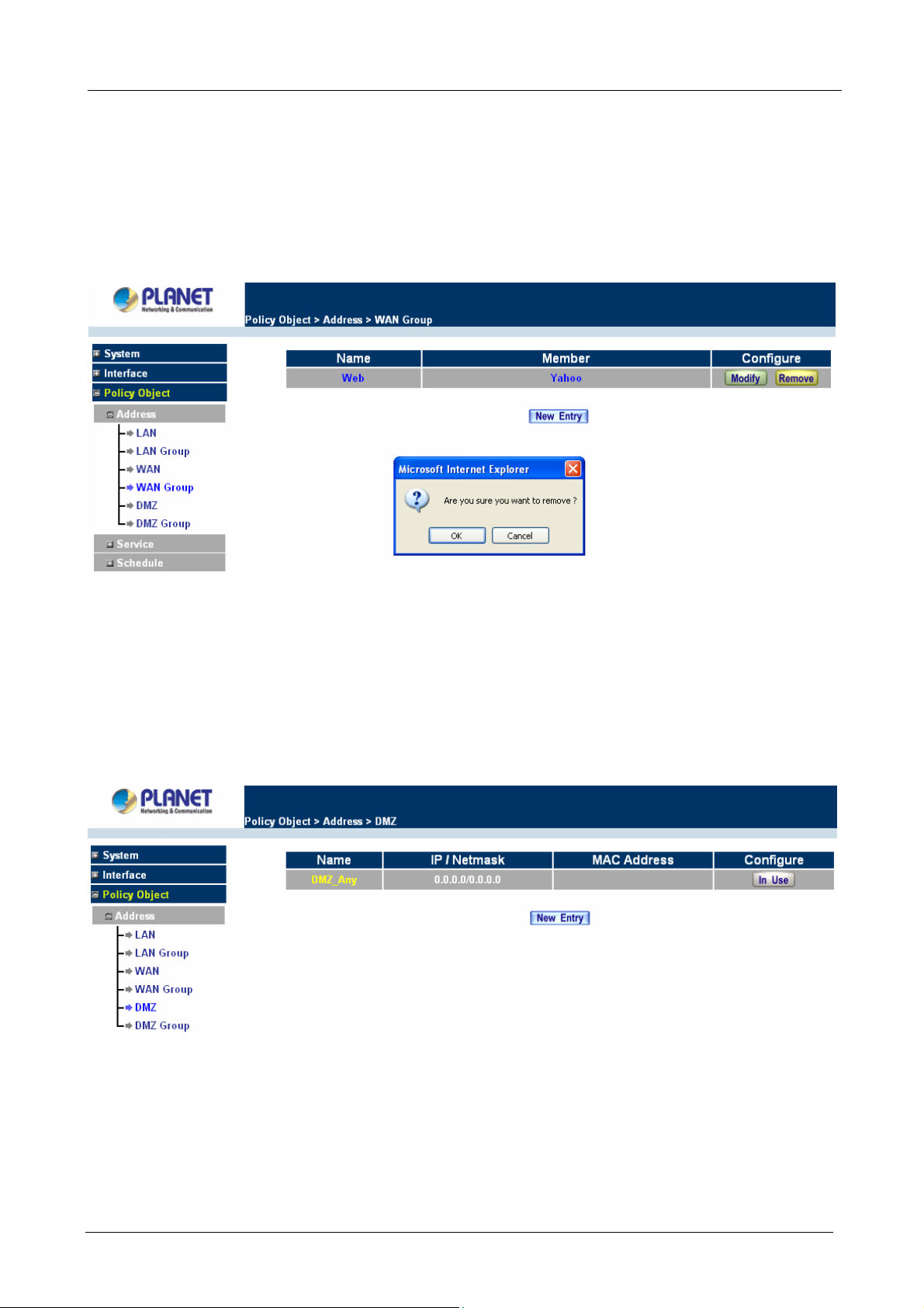
Multi-Homing Security Gateway User’s Manual
Removing a W AN Group
Step 1. In the WAN Group window, locate the group to be removed and click its corresponding Modify
option in the Configure field.
Step 2. In the Remove confirmation pop-up box, click OK to remove the group or click Cancel to discard
changes.
3.3.1.5 DMZ
Entering the DMZ window:
Click DMZ under the Address menu to enter the DMZ window. The current setting information such as the
name of the LAN network, IP, and Netmask addresses will show on the screen.
Adding a new DMZ Address:
Step 1. In the DMZ window, click the New Entry button.
Step 2. In the Add New Address window, enter the settings for a new DMZ address.
- 50 -
Page 57
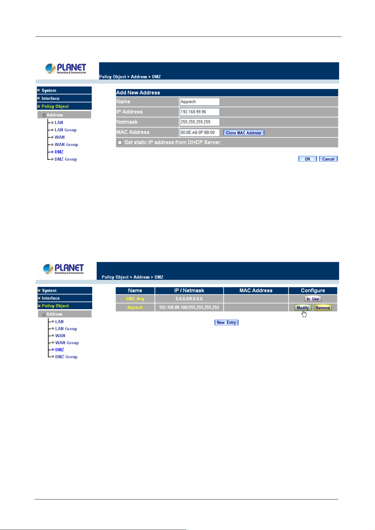
Multi-Homing Security Gateway User’s Manual
Step 3. Click OK to add the specified DMZ or click Cancel to discard changes.
Modifying a DMZ Address:
Step 1. In the DMZ window, locate the name of the network to be modified and click the Modify option in
its corresponding Configure field.
Step 2. In the Modify Address window, fill in new addresses.
Step 3. Click OK on save the changes or click Cancel to discard changes.
Removing a DMZ Address:
Step 1. In the DMZ window, locate the name of the network to be removed and click the Remove option in
its corresponding Configure field.
Step 2. In the Remove confirmation pop-up box, click OK to remove the address or click Cancel to discard
changes.
- 51 -
Page 58

3.3.1.6 DMZ Group
Multi-Homing Security Gateway User’s Manual
Entering the DMZ Group window
Click DMZ Group under the Address menu to enter the DMZ window. The current settings information for the
DMZ group appears on the screen.
Adding a DMZ Group:
Step 1. In the DMZ Group window, click the New Entry button.
Step 2. In the Add New Address Group window:
Available address: list names of all members of the DMZ.
Selected address: list names to assign to a new group.
Step 3. Name: enter a name for the new group.
- 52 -
Page 59

Multi-Homing Security Gateway User’s Manual
Step 4. Add members: Select the names to be added from the Available address list, and click the
Add>> button to add them to the Selected address list.
Step 5. Remove members: Select names to be removed from the Selected address list, and click the
<<Remove button to remove them from the Selected address list.
Step 6. Click OK to add the new group or click Cancel to discard changes.
Modifying a DMZ Group:
Step 1. In the DMZ Group window, locate the DMZ group to be modified and click its corresponding
Modify button in the Configure field.
Step 2. A window displaying information about the selected group appears:
Available address: list the names of all the members of the DMZ.
Selected address: list the names of the members that have been assigned to this group.
Step 3. Add members: Select names to be added from the Available Address list, and click the Add>>
button to add them to the Selected address list.
Step 4. Remove members: Select names to be removed from the Selected address list, and click the
<<Remove button to remove them from Selected address list.
Step 5. Click OK to save changes or click Cancel to cancel editing.
- 53 -
Page 60
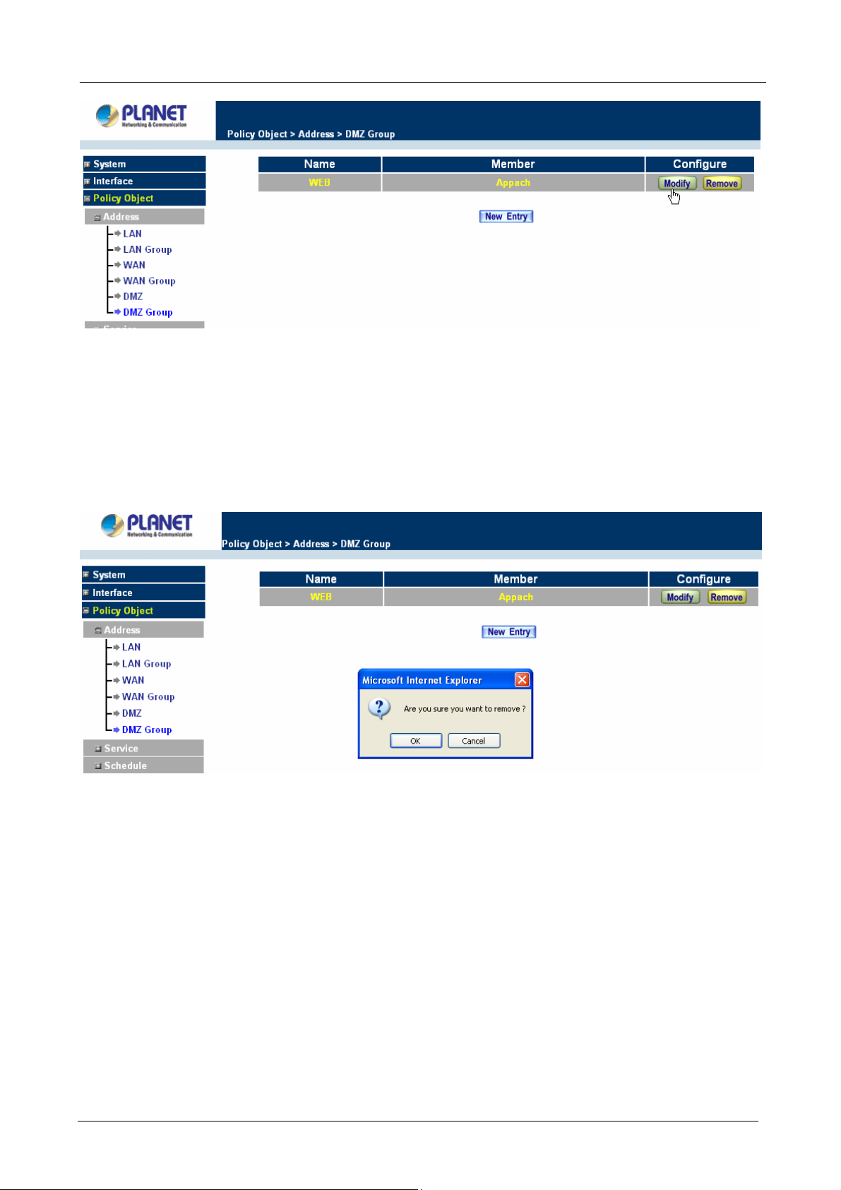
Multi-Homing Security Gateway User’s Manual
Removing a DMZ Group:
Step 1. In the DMZ Group window, locate the group to be removed and click its corresponding Remove
option in the Configure field.
Step 2. In the Remove confirma tion pop-up box, click OK to remove the group.
3.3.2 Service
In this section, network services are defined and new network services can be added. There are three sub
menus under Service which are: Pre-defined, Custom, and Group. The Administrator can simply follow the
instructions below to define the protocols and port numbers for network communication applications. Users
then can connect to servers and other computers through these available network services.
What is Service?
TCP and UDP protocols support varieties of services, and each service consists of a TCP Port or UDP port
number, such as TELNET(23), SMTP(21), POP3(110),etc. The Multi-Homing Security Gateway defines two
services: pre-defined service and custom service. The common-use services like TCP and UDP are defined in
- 54 -
Page 61
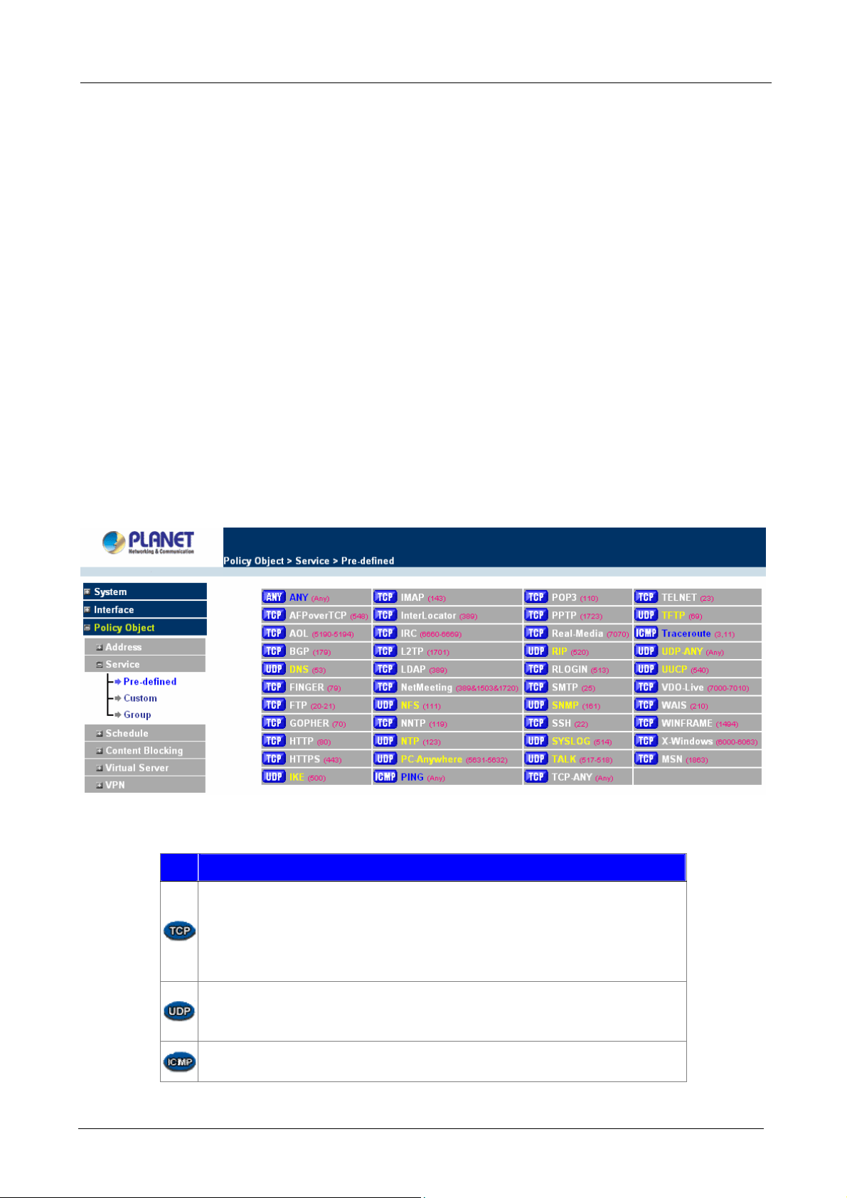
Multi-Homing Security Gateway User’s Manual
the pre-defined service and cannot be modified or removed. In the custom menu, users can define other TCP
port and UDP port numbers that are not in the pre-defined menu according to their needs. When defining
custom services, the client port ranges from 1024 to 65535 and the server port ranges from 0 to 1023.
How do I use Service?
The Administrator can add new service group names in the Group option under Service menu, and assign
desired services into that new group. Using service group the Administrator can simplify the processes of
setting up control policies. For example, there are 10 different computers that want to access 5 different
services on a server, such as HTTP, FTP, SMTP, POP3, and TELNET. Without the help of service groups, the
Administrator needs to set up 50 (10x5) control policies, but by applying all 5 services to a single group name
in the service field, it takes only one control policy to achieve the same effect as the 50 control policies.
3.3.2.1 Pre-defined
Entering a Pre-defined window
Step 1. Click Pre-defined under it. A window will appear with a list of services and their associated IP
addresses. This list cannot be modified.
ÍÍ
Icons and Descriptions
Figur
Description
TCP services, e.g. AFPoverTCP, AOL, BGP, FINGER, FTP, GOPHER, HTTP,
HTTPS, IMAP, InterLocator, IRC, L2TP, LDAP, NetMeeting, NNTP, POP3,
PPTP, Real-Media, RLOGIN, SMTP, SSH, TCP-ANY, TELNET, VDO-Live,
WAIS, WINFRAME, X-Windows, MSN, etc.
UDP services, e.g. DNS, IKE, NFS, NTP, PC-Anywhere, RIP, SNMP,
SYSLOG, TALK, TFTP, UDP-ANY, UUCP, etc.
ICMP services, i.g. PING, Traceroute, etc.
- 55 -
Page 62

Multi-Homing Security Gateway User’s Manual
3.3.2.2 Custom
Entering the Custom window
Step 1. Click Custom under it. A window will appear with a table showing all services currently defined
by the Administrator.
ÍÍ
Definitions:
Service name: The defined service name.
Protocol: Network protocol used in the basic setting. Such as TCP、UDP or others.
Client port: The range of Client port in defined service. If the number of ports entered in the two fields of
Client port is different, it means that the port numbers between these two numbers are opened. If the number
of ports entered in the two fields of Client port is identical, it means that the entered port number is opened.
Service port: The range of Service port in defined service.
If the number of ports entered in the two fields of Service port is different, it means that the port numbers
between these two numbers are opened. If the number of ports entered in the two fields of Service port is
identical, it means that the entered port number is opened.
Configure: Configure the settings in Service table. Click Modify to change the parameters in Service table.
Click Remove to delete the selected setting.
NOTE: In the Custom window, if one of the services has been added to Policy or Group, ”In Use” message
will appear in the Configure column. In this case you are not allowed to modify or remove the settings. Go to
the Policy or Group window to delete the setting, and then you can configure the settings.
Adding a new Service
In the Custom window, click the New Entry button and a new service table appears.
In the new service table:
New Service Name: This will be the name referencing the new service.
Protocol: Enter the network protocol type to be used, such as TCP, UDP, or Other (please
enter the number for the protocol type).
Client Port: enter the range of port number of new clients.
Server Port: enter the range of port number of new servers.
The client port and server port ranges are from 0 to 65535.
- 56 -
Page 63
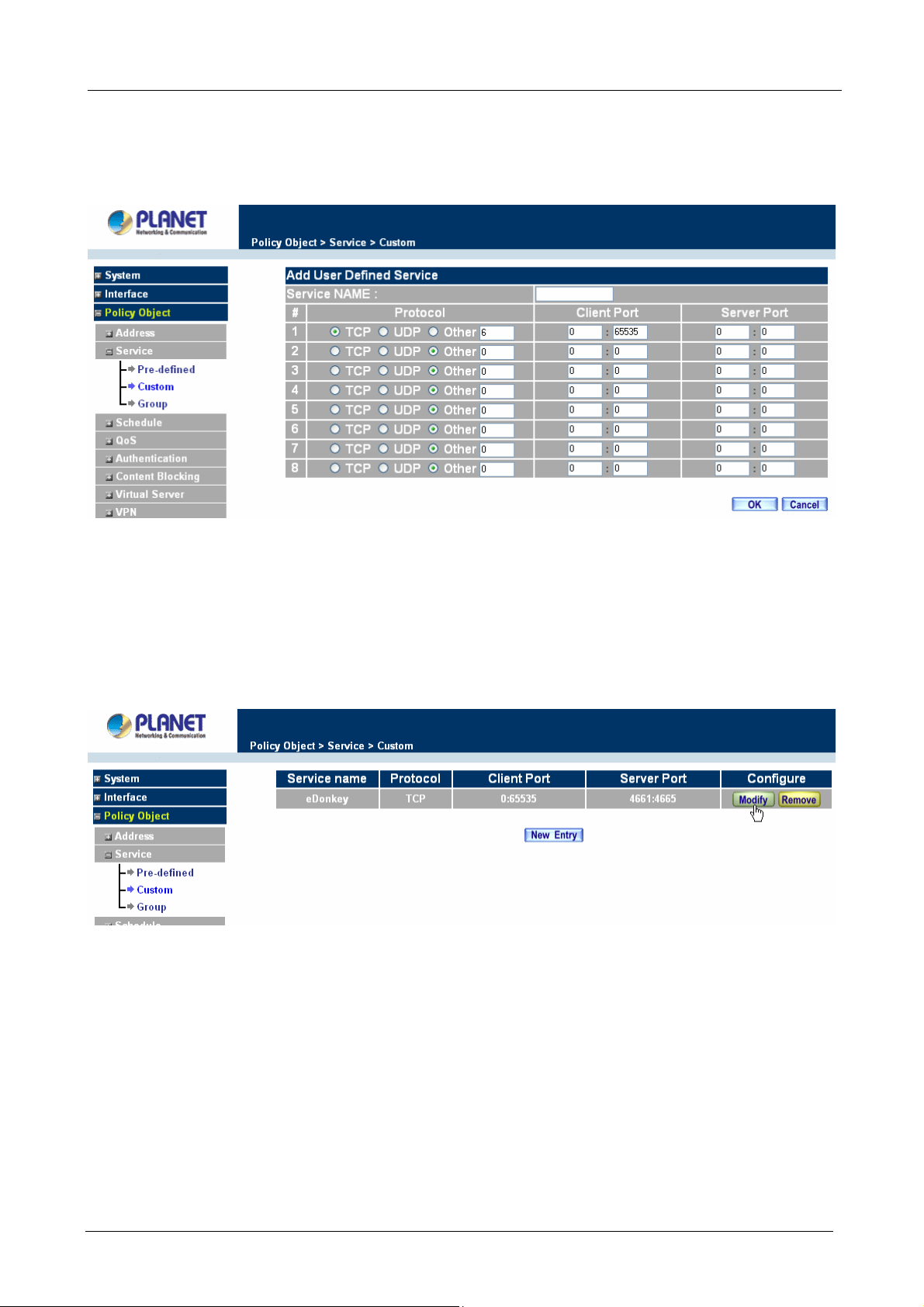
Step 1. Click New Entry to add new services.
Step 2. Click OK to accept editing, or click Cancel.
Multi-Homing Security Gateway User’s Manual
Modifying Custom Services
Step 1. A table showing the current settings of the selected service appears on the screen
Step 2. Enter the new values.
Step 3. Click OK to accept editing; or click Cancel.
Removing Custom Services
Step 1. Click its corresponding Remove option in the Configure field.
Step 2. In the Remove confirmation pop-up box, click OK to remove the selected service or click
Cancel to cancel action.
- 57 -
Page 64

Multi-Homing Security Gateway User’s Manual
3.3.2.3 Group
Accessing the Group window
Step 1. Click Group under it. A window will appear with a table displaying current service group settings
set by the Administrator.
Definitions:
Group name: The Group name of the defined Service.
Service: The Service item of the Group.
Configure: Configure the settings of Group. Click Modify to change the parameters of the Group. Click
Remove to delete the Group.
NOTE: In the Group window, if one of the Service Groups has been added to Policy. “In Use” message will
appear in the Configure column. You are not allowed to modify or remove the settings. Go to the Policy
ÍÍ
window, remove the Service group first, and then you are allowed to configure the setting.
Adding Service Groups
Step 1. In the Group window, click the New Entry button.
Step 2. In the Add Service Group window, the following fields will appear:
Available service: list all the available services.
Selected service: list services to be assigned to the new group.
- 58 -
Page 65
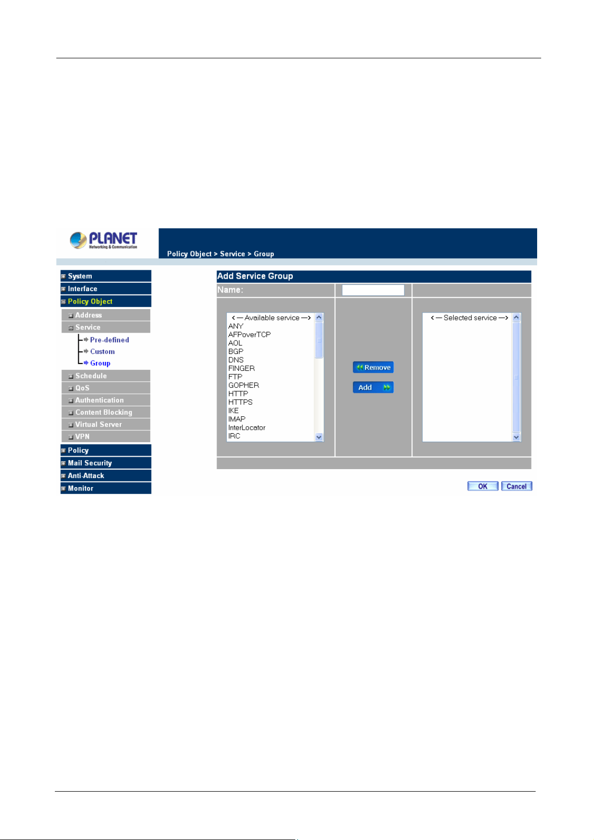
Multi-Homing Security Gateway User’s Manual
Step 3. Enter the new group name in the group Name field. This will be the name referencing the
created group.
Step 4. To add new services: Select the services desired to be added in the Available service list and
then click the Add>> button to add them to the group.
Step 5. To remove services: Select services desired to be removed in the Available service, and then
click the <<Remove button to remove them from the group.
Step 6. Click OK to add the new group.
Modifying Service Groups
Step 1. In the Mod (modify) group window the following fields are displayed:
Available service: lists all the available services.
Selected service: list services that have been assigned to the selected group.
Step 2. Add new services: Select services in the Available service list, and then click the Add>>
button to add them to the group.
Step 3. Remove services: Select services to be removed in the Selected service list, and then click
the <<Remove button to remove theses services from the group.
Step 4. Click OK to save editing changes.
- 59 -
Page 66

Multi-Homing Security Gateway User’s Manual
Removing Service Groups
In the Remove confirmation pop-up box, click OK to remove the selected service group or click Cancel to
cancel removing.
3.3.3 Schedule
The Multi-Homing Security Gateway allows the Administrator to configure a schedule for policies to take affect.
By creating a schedule, the Administrator is allowing the Multi-Homing Security Gateway policies to be used
at those designated times only. Any activities outside of the scheduled time slot will not follow the
Multi-Homing Security Gateway policies therefore will likely not be permitted to pass through the Multi-Homing
Security Gateway. The Administrator can configure the start time and stop time, as well as creating 2 different
time periods in a day. For example, an organization may only want the Multi-Homing Security Gateway to
allow the LAN network users to access the Internet during work hours. Therefore, the Administrator may
create a schedule to allow the Multi-Homing Security Gateway to work Monday-Friday, 8AM - 5PM only.
During the non-work hours, the Multi-Homing Security Gateway will not allow Internet access.
Accessing the Schedule window
Step 1. Click on Setting on the Schedule menu bar and the schedule window will appear displaying the
active schedules.
- 60 -
Page 67

Multi-Homing Security Gateway User’s Manual
The following items are displayed in this window:
Name: the name assigned to the schedule
Configure: modify or remove
Adding a new Schedule
Step 1. Click on the New Entry button and the Add New Schedule window will appear.
Schedule Name: Fill in a name for the new schedule.
Period: Configure the start and stop time for the days of the week that the schedule will be
active.
Step 2. Click OK to save the new schedule or click Cancel to cancel adding the new schedule.
NOTE: In setting a Schedule, the value in Start time must be less than the value in Stop Time, or you cannot
add or configure the setting.
Modifying a Schedule
- 61 -
Page 68
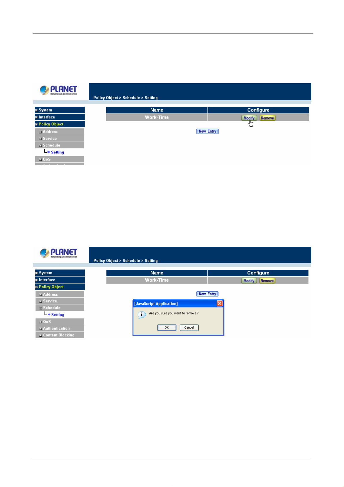
Multi-Homing Security Gateway User’s Manual
Step 1. In the Schedule window, find the policy to be modified and click the corresponding Modify option
in the Configure field. Make needed changes.
Step 2. Click OK to save changes.
Removing a Schedule
Step 1. In the Schedule window, find the policy to be removed and click the corresponding Remove
option in the Configure field.
Step 2. A confirmation pop-up box will appear, click on OK to remove the schedule.
3.3.4 QoS
By configuring the QoS, you can control the outbound Upstream/downstream Bandwidth.
Before to configure QoS setting, the WAN port downstream and upstream bandwidth setting must be
configured first, or the QoS setting will not be available to be configured.
Configuration of QoS
Click QoS in the menu bar on the left hand side.
- 62 -
Page 69
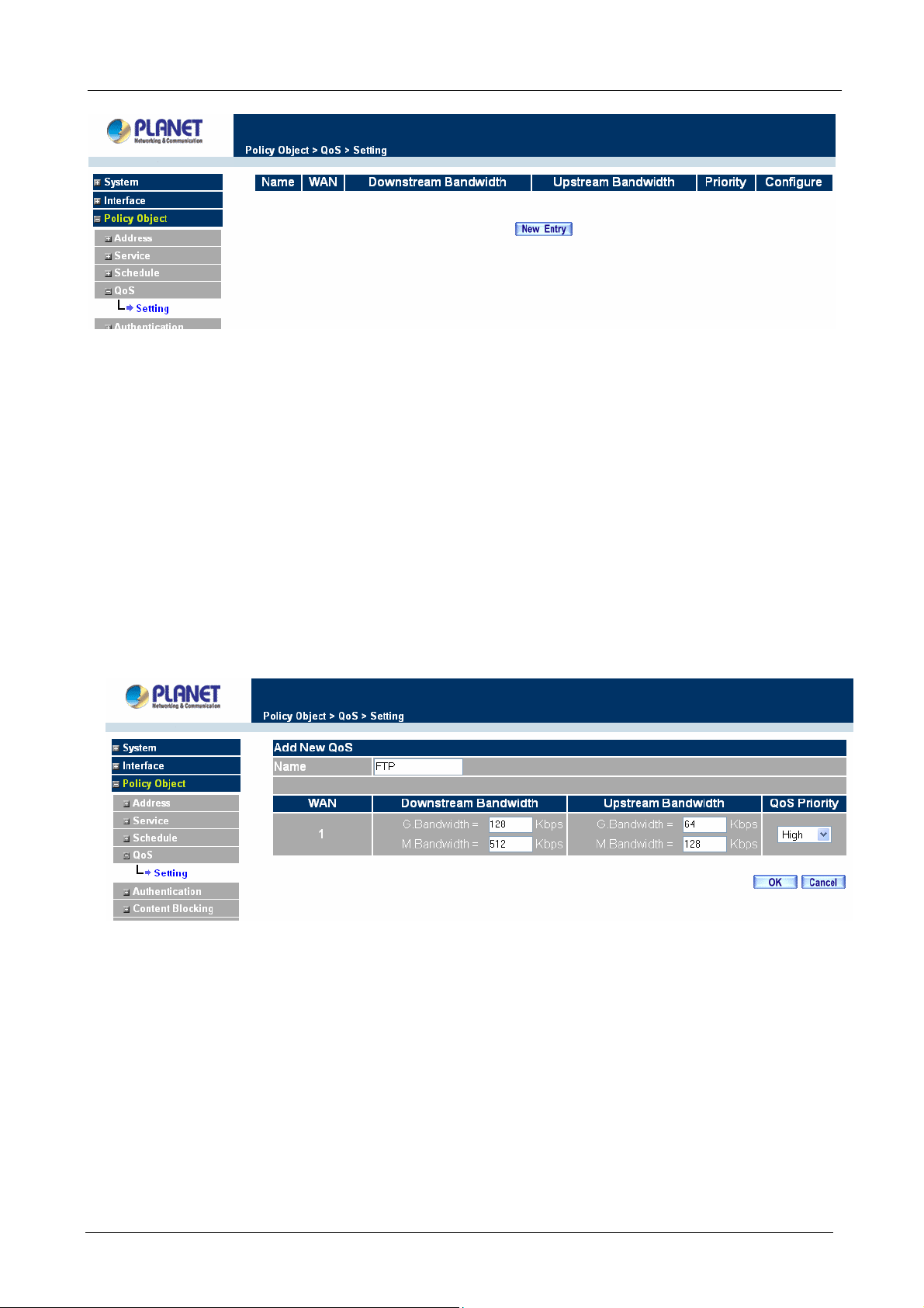
Multi-Homing Security Gateway User’s Manual
ÍÍ
Definitions:
Name: The name of the QoS you want to configure.
WAN: Display WAN interface.
Downstream Bandwidth: To configure the Guaranteed Bandwidth and Maximum Bandwidth.
Upstream Bandwidth: To configure the Guaranteed Bandwidth and Maximum Bandwidth.
Priority: To configure the priority of distributing Upstream/Downstream and unused bandwidth.
Add New QoS
Step 1. Click QoS in the menu bar on the left hand side.
Step 2. Click the New Entry button to add new QoS.
Definition
Name: The name of the QoS you want to configure.
Downstream Bandwidth: To configure the Guarateed Bandwidth and Maximum Bandwidth.
Upstream Bandwidth: To configure the Guarateed Bandwidth and Maximum Bandwidth.
QoS Priority: To configure the priority of distrubuting Upstream/Downstream and unused bandwidth.
Click the OK button to add new QoS.
Modify QoS
Step 1. In the QoS window, find the QoS you want to modify, and click Modify in the Configure column.
- 63 -
Page 70

Multi-Homing Security Gateway User’s Manual
Step 2. Click the OK button to modify QoS
Delete QoS
Step 1. In the QoS window, find the QoS you want to change, and click Delete in the Configure
column.
Step 2. In the Delete QoS window, click OK to delete the QoS or click Cancel to discard the change.
Example about how to configure QoS correctly
Step 1. Select and configure the correct connection type, including downstream/upstream bandwidth.
- 64 -
Page 71
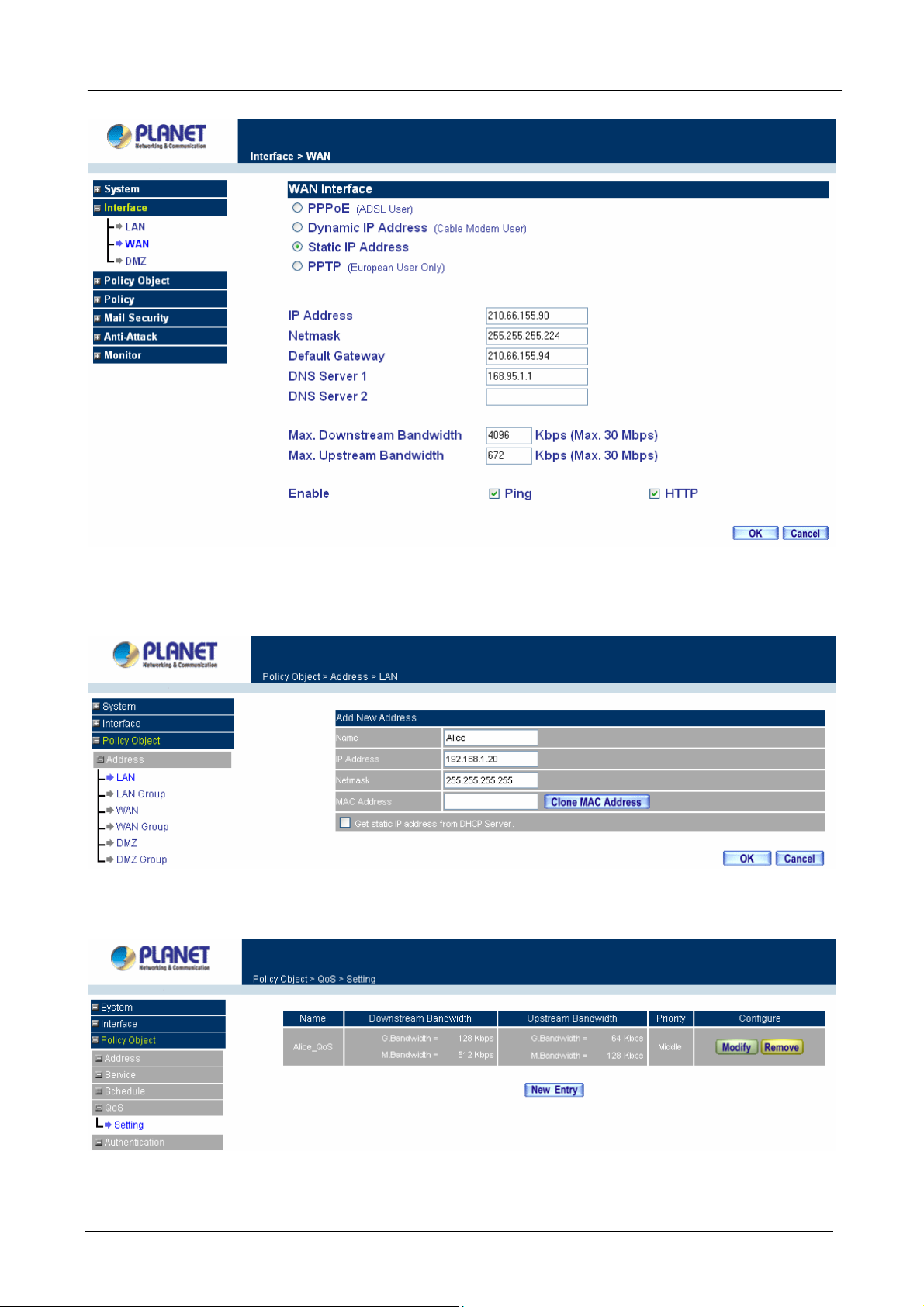
Multi-Homing Security Gateway User’s Manual
Step 2. Configure the LAN host or WAN host IP address that need to filter with QoS feature. Be aware
that the Netmask must set to 255.255.255.255 if you only want to configure a single IP address.
Step 3. Set up the QoS rule.
- 65 -
Page 72

Multi-Homing Security Gateway User’s Manual
Step 4. Enable the QoS rule in Outgoing or Incoming Policy.
3.3.5 Authentication
By configuring the Authentication, you can control the user’s access right time of LAN to WAN. The
administrator can configure the authentication according to the authentication account and password.
CS-1000 configures the authentication of LAN user by setting account and password to identify the privilege.
3.3.5.1 Auth Setting
The administrator can specify the port number and authentication time of authentication management system
for LAN user to access WAN network.
Configuration of Authentication
Click Authentication in the menu bar on the left hand side and click Auth Setting.
- 66 -
Page 73
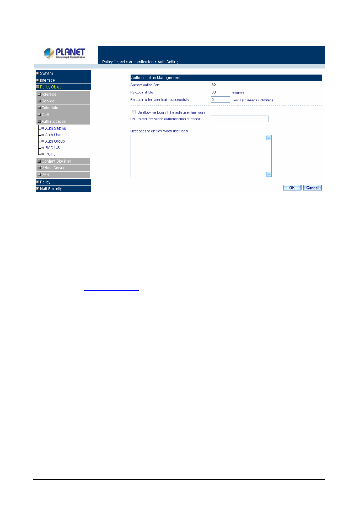
Multi-Homing Security Gateway User’s Manual
Authentication Port: The port number used for user login page.
Generally, when user wants to access WAN network and the authentication (Policy -> Outgoing) is enabled,
the user only need to open a web page and the User Login page will pop up.
But if user does not need to open the web page and also want to access Internet resource such as FTP, then
the user has to send http request with this port number, and CS-1000 will send a User Login page for user to
input user name and password.
For example, if the gateway IP address is 192.168.1.1 and authentication port is 82, user have to open a web
browser and input
Re-Login if Idle: When the LAN users access to WAN network and stop to access Internet for a while, the
connection will be time-out. User has to re-login again. The default time is 30 minutes.
Re-Login after user login successfully: You can limit the access time for the LAN user, when time is up
LAN user will need to re-login again. If the time setting sets to 0, that means unlimited. Select Disallow
Re-login if the auth user has login will disable this feature.
URL to redirect when authentication succeed: You can set up the default webpage, the function will force
http://192.168.1.1:82 on the address file to have the user login page.
user to access the default webpage first when user passes the authentication.
Messages to display when user login: You can specify a message to display at user’s login page.
3.3.5.2 Auth User
Click Authentication in the menu bar on the left hand side and click Auth User.
- 67 -
Page 74

Multi-Homing Security Gateway User’s Manual
Definitions:
Name:The name of the Authentication you want to configure.
Configure: Modify settings or remove users.
Adding a new Auth User
Step 1. In the Authentication window, click the New Entry button to create a new Auth User.
Step 2. In the Auth-User window:
Auth-User Name: enter the username of new Authentication.
Password: enter a password for the new Authentication.
Con firm Password: enter the password again.
Step 3. Click OK to add the user or click Cancel to cancel the addition.
- 68 -
Page 75

Multi-Homing Security Gateway User’s Manual
Step 4. Create an Outgoing Policy rule to allow DNS protocol pass through first, then to create another
Outgoing Policy rule to enable Authentication-User Function.
Step 5. Before user can access Internet, the User Login Page will pop up as following, then to input the user
name and password.
User Login Page Definitions:
User Name: The name of the Authentication you want to configure.
Password: The input carries on the authentication the password
Modifying the Authentication User
Step 1. In the Authentication window, locate the Auth-User name you want to edit, and click on Modify
in the Configure field.
Step 2. The Modify Auth-User Password window will appear. Enter in the required information:
Auth-User: show original authentication user.
- 69 -
Page 76
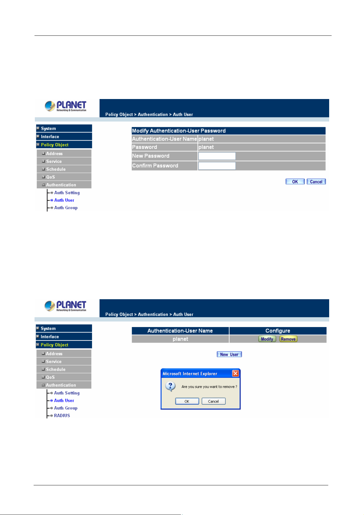
Multi-Homing Security Gateway User’s Manual
Password: show original password.
New Pa ssword: enter new password
Confirm Password: enter the new password again.
Step 3. Click OK to confirm authentication user change or click Cancel to cancel it.
Removing a Authentication User
Step 1. In the Authentication table, locate the Auth-User name you want to edit, and click on the Remove
option in the Configure field.
Step 2. The Remove confirmation pop-up box will appear.
Step 3. Click OK to remove that Authentication User or click Cancel to cancel.
3.3.5.3 Auth Group
Accessing the Auth Group window
Click Authentication in the menu bar on the left hand side of the window, then to click Auth Group under it.
- 70 -
Page 77
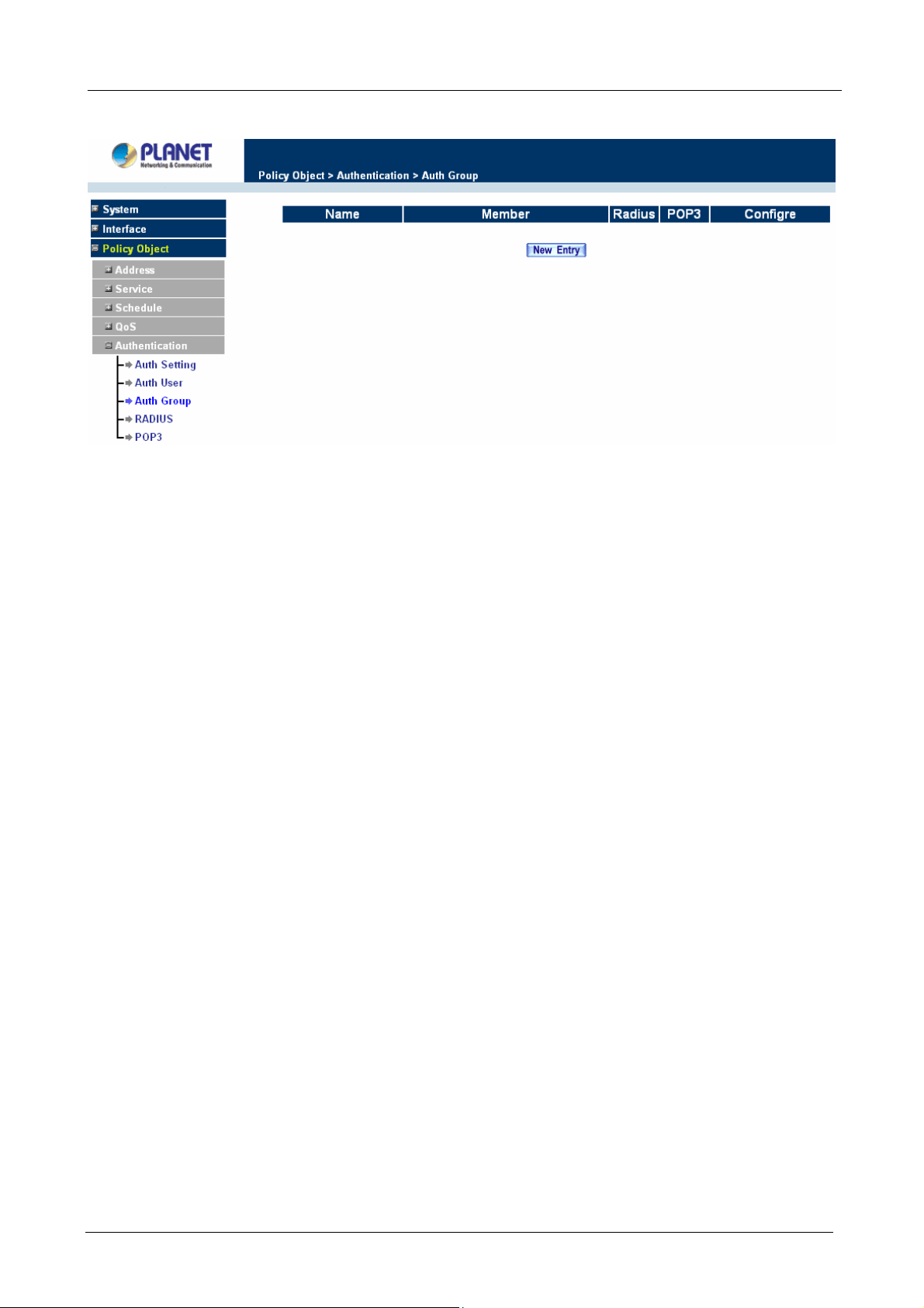
Multi-Homing Security Gateway User’s Manual
A window will appear with a table displaying current Auth Group settings.
Adding Auth Group
Step 1. In the Auth Group window, click the New Entry button.
In the Auth Group window, the following fields will appear:
Name: Enter the new Auth Group name.
Available auth user: List all the available Auth User.
Selected auth user: List Auth User to be assigned to the new group.
Step 2. Enter the new group name in the group Name field. This will be the name referencing the created
group.
Step 3. To add new Auth User: Select the Auth User desired to be added in the Available auth user list,
and then click the Add>> button to add them to the group.
Step 4. To remove Auth User: Select Auth User desired to be removed in the Available auth user list, and
then click the <<Remove button to remove them from the group.
Step 5. Click OK to add the new group.
- 71 -
Page 78
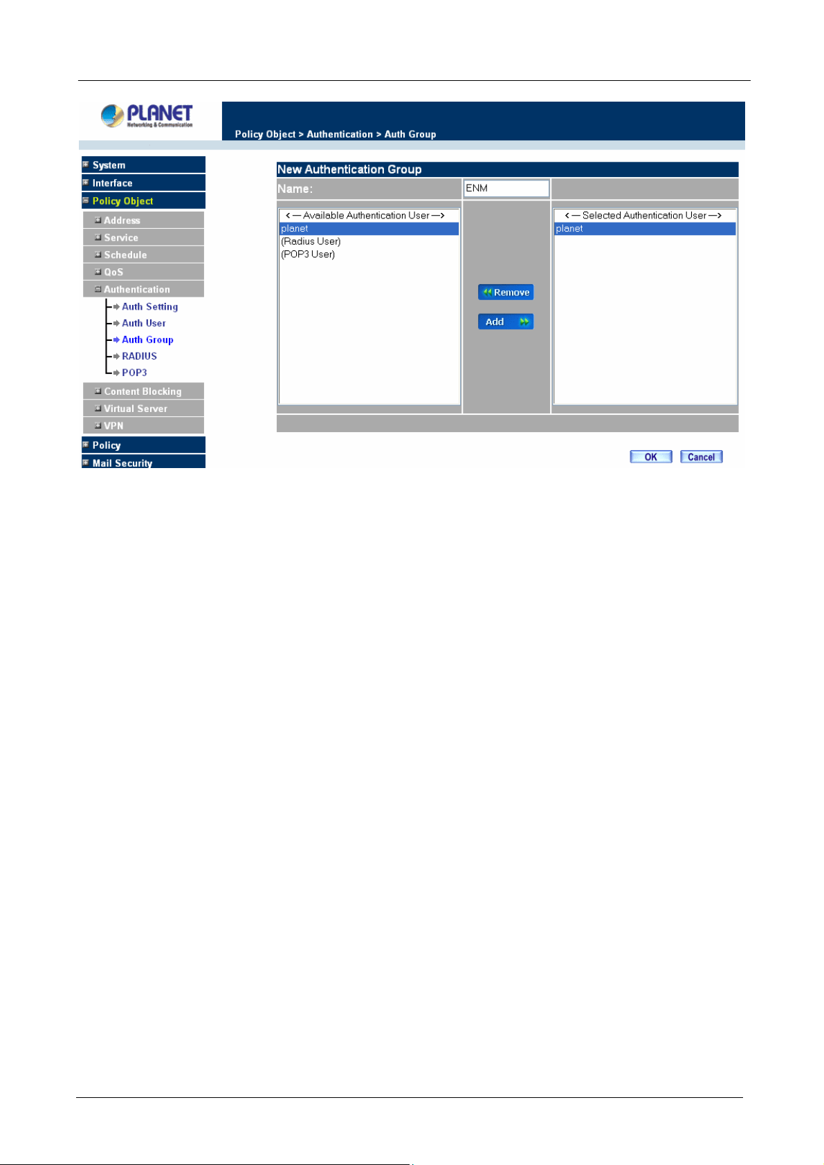
Multi-Homing Security Gateway User’s Manual
Modifying Auth Group
Step 1. In the Auth Group window, locate the Auth Group to be edited. Click its corresponding Modify
option in the Configure field.
Step 2. In the Modify Auth group window the following fields are displayed::
Name: Enter the new Auth Group name .
Available auth user: List all the available Auth User.
Selected auth user: List Auth User to be assigned to the new group.
Step 3. To add new Auth User: Select the Auth User desired to be added to the Available auth user list,
and then click the Add>> button to add them to the group.
Step 4. To remove Auth User: Select Auth User desired to be removed from the Available auth user list,
and then click the <<Remove button to remove them from the group.
Step 5. Click OK to modify the Group.
- 72 -
Page 79
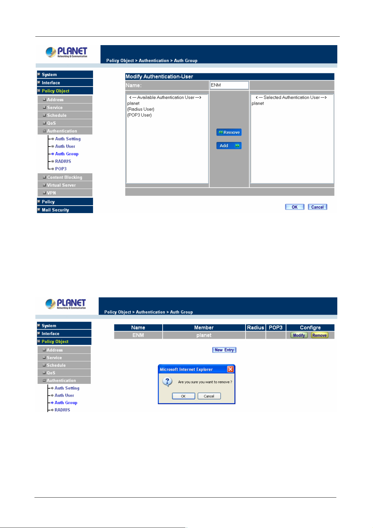
Multi-Homing Security Gateway User’s Manual
Removing Auth Group
Step 1. In the Auth Group window, locate the Auth Group to be removed and click its corresponding
Remove option in the Configure field.
Step 2. In the Remove confirmation pop-up box, click OK to remove the selected service group or click
Cancel to cancel removing.
3.3.5.4 Radius Serve
Click Authentication on the left side menu bar, then click Radius Server below it. The following window is
shown.
- 73 -
Page 80
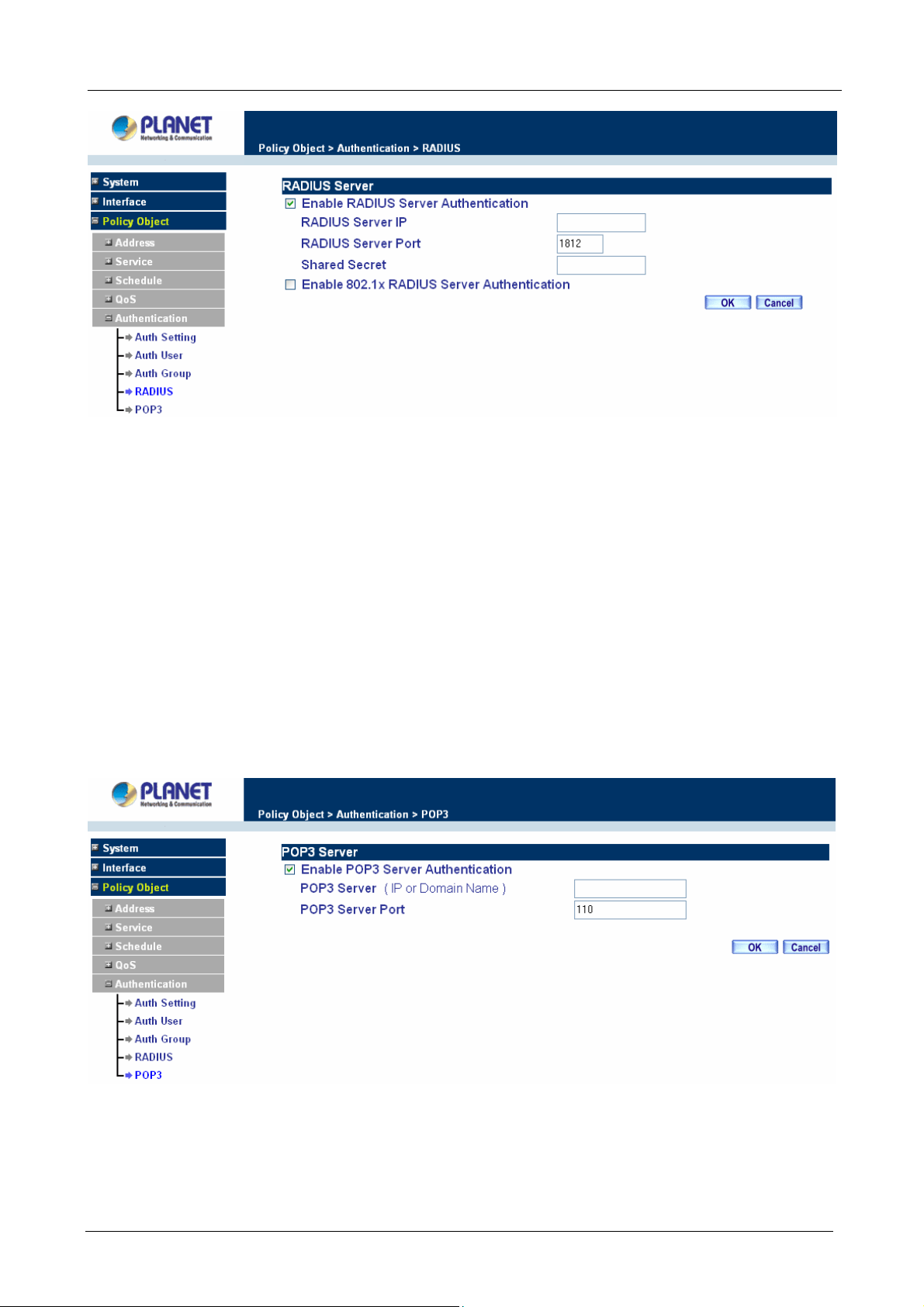
Definition
Multi-Homing Security Gateway User’s Manual
Enable RADIUS Server: Enable RADIUS Server Authentication.
RADIUS Server IP: Enter RADIUS Server IP address.
RADIUS Server Port: Enter RADIUS Server Port. The default port is 1812.
Shared Secret: The Password for CS-1000 to access RADIUS Server.
Enable 802.1x RADIUS Server Authentication: Enable 802.1x RADIUS Server
Authentication.
3.3.5.5 POP3
Click Authentication on the left side menu bar, then click POP3 below it. The following window is shown.
Definition
Enable POP3 Server: Enable POP3 Server Authentication.
POP3 Server : Enter POP3 Server IP address or domain name.
- 74 -
Page 81

Multi-Homing Security Gateway User’s Manual
POP3 Server Port: Enter POP3 Server Port. The default port is 110.
3.3.6 Content Blocking
Content Blocking includes “URL”, “Scripts”, “P2P”, “IM”, “Download” and “Upload”.
URL: The administrator can use a complete domain name or key word to make rules for specific websites.
Scripts : To let Popup、ActiveX、Java、Cookie in or keep them out.
P2P : Block P2P program, include “eDonkey”, “Bit Torrent“ and “WinMX”.
IM : Block Internet Message program, include “MSN”, “Yahoo Messenger”, “ICQ”, “QQ” and “Skype”.
Download : Block download connection, audio and video transferring from web page. You can select to block
which type of extension name or all type of the file.
Upload : Block upload connection, audio and video transferring from web page. You can select to block which
type of extension name or all type of the file.
3.3.6.1 URL Blocking
The Administrator may setup URL Blocking to prevent LAN network users from accessing a specific website
on the Internet. Any web request coming from LAN network computer to a blocked website will receive a
blocked message instead of the website.
Entering the URL blocking window
Step 1. Click on URL under the Content Blocking menu bar.
Step 2. Click on New Entry.
ÍÍ
Definition:
- 75 -
Page 82
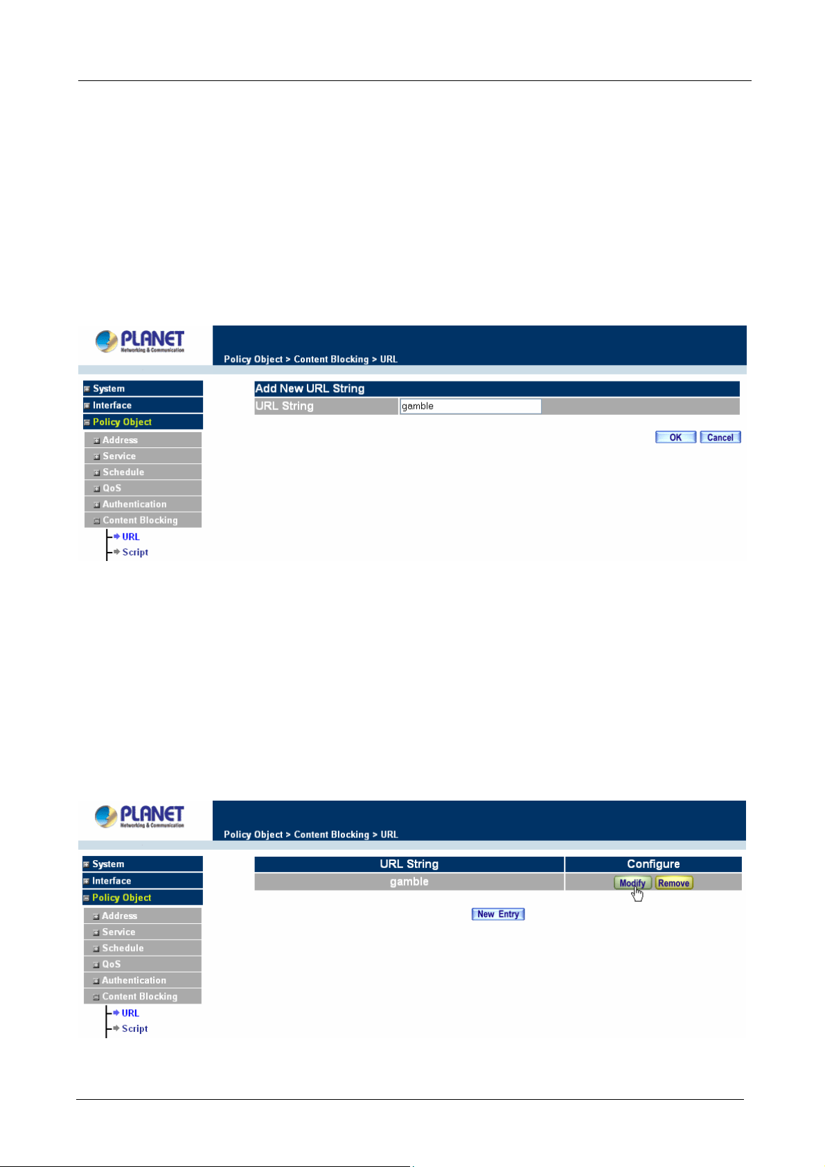
Multi-Homing Security Gateway User’s Manual
URL String: The domain name that is blocked to enter by Multi-Homing Security Gateway.
Configure: To change the settings of URL Blocking, click Modify to change the parameters; click Delete to
delete the settings.
Adding a URL policy
Step 1. After clicking New Entry, the Add New URL St ring window will appear.
Step 2. Enter the URL of the website to be blocked.
Step 3. Click OK to add the policy. Click Cancel to discard changes.
Step 4. Configure Outgoing Policy rule to enable Content Blocking Function.
When the system detects the setting, the Multi-Homing Security Gateway will spontaneously work.
Modifying a URL String Policy
Step 1. In the URL window, find the policy to be modified and click the corresponding Modify option in
the Configure field.
Step 2. Make the necessary changes needed.
Step 3. Click on OK to save changes or click on Cancel to discard changes.
- 76 -
Page 83

Multi-Homing Security Gateway User’s Manual
Removing a URL String policy
Step 1. In the URL window, find the policy to be removed and click the corresponding Remove option in
the Configure field.
Step 2. A confirmation pop-up box will appear, click on OK to remove the policy or click on Cancel to
discard changes.
3.3.6.2 Scripts
To let Popup, ActiveX, Java, or Cookies in or keep them out.
Step 1: Click Scripts below Co ntent Blocking menu.
Step 2: Select Scripts detective functions:
Popup Blocking: Prevent pop-up boxes from appearing.
ActiveX Blocking: Prevent ActiveX packets.
Java Blocking: Prevent Java packets.
Cookie Blocking: Prevent Cookie packets.
Step 3: After selecting each function, click the OK button below.
- 77 -
Page 84

Multi-Homing Security Gateway User’s Manual
Step 4: Configure Outgoing Policy rule to enable Content Blocking Function.
When the system detects the setting, the Multi-Homing Security Gateway will spontaneously work.
3.3.6.3 P2P
Step 1: Click P2P below Content Blocking menu.
Step 2: Select P2P detective functions:
eDonkey Blocking: Prevent eDonkey connection built up.
Bit Torrent Blocking: Prevent Bit Torrent connection built up.
WinMX Blocking: Prevent WinMX connection built up.
Step 3: After selecting each function, click the OK button below.
ÍÍ
Step 4: Configure Outgoing Policy rule to enable Content Blocking Function.
- 78 -
Page 85
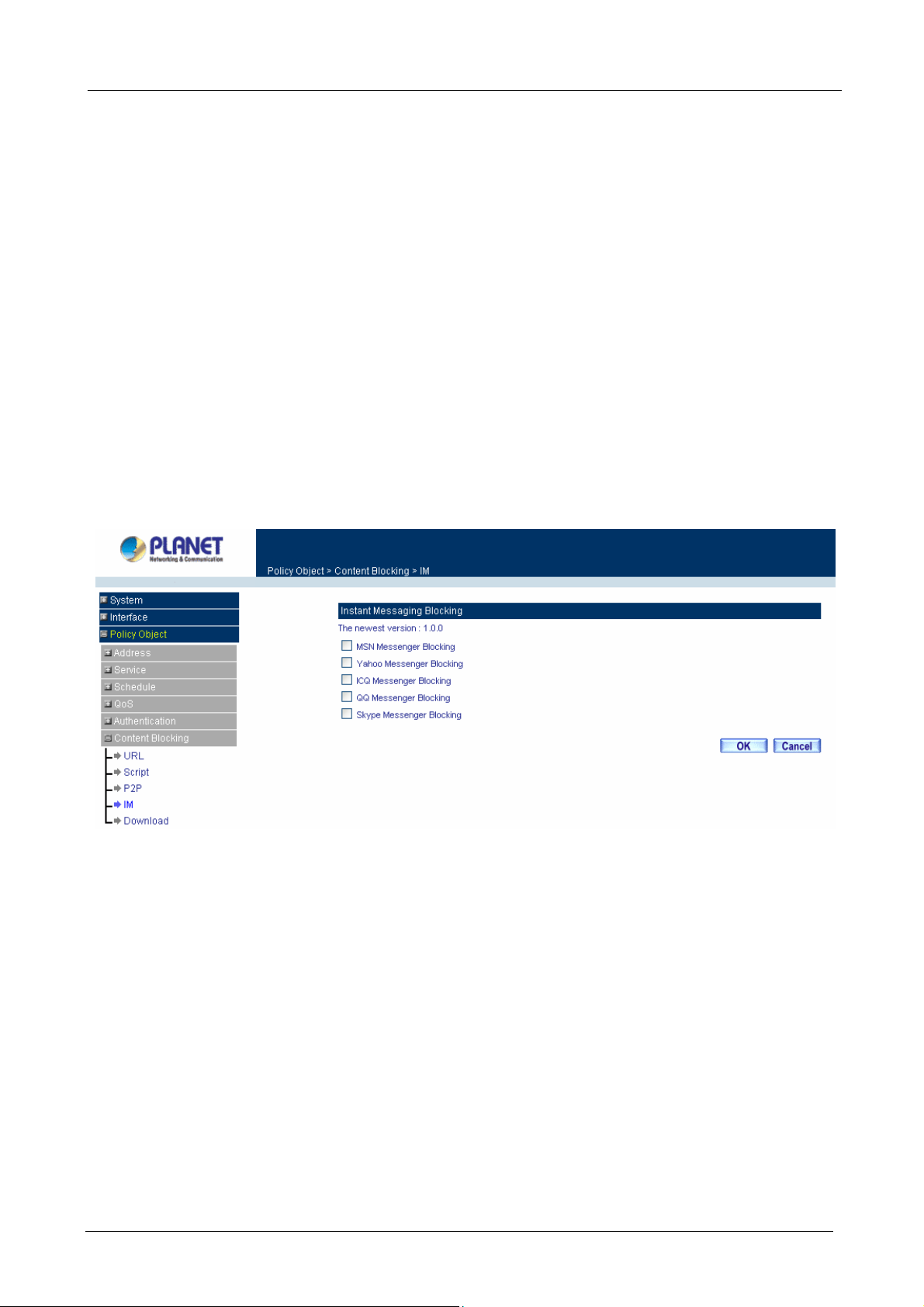
Multi-Homing Security Gateway User’s Manual
CS-1000 provides a feature that will auto detect the P2P program version. When it detects a new version P2P
program in the LAN site, CS-1000 will connect to Internet and download the pattern to update the P2P
Blocking function, and to keep the function working well to block new version P2P program. The current
pattern version will display at the top side.
3.3.6.4 IM
Step 1: Click IM below Content Blocking menu.
Step 2: Select IM detective functions:
MSN Messenger Blocking: Select to block MSN Messenger.
Yahoo Messenger Blocking: Select to block Yahoo Messenger.
ICQ Blocking: Select to block ICQ.
QQ Blocking: Select to block QQ.
Skype Messenger Blocking: Select to block Skype.
Step 3: After selecting each function, click the OK button below.
ÍÍ
Step 4: Configure Outgoing Policy rule to enable Content Blocking Function.
CS-1000 provides a feature that will auto detect the IM program version. When it detects a new version IM
program in the LAN site, CS-1000 will connect to Internet and download the pattern to update the IM Blocking
function, and to keep the function working well to block new version IM program. The current pattern version
will display at the top side.
3.3.6.5 Download
Step 1: Click Download below Content Blocking menu.
Step 2: Select Download detective functions:
All Types Block: To block all types of the files downloading from web page.
Audio and Video Types block: To block audio and video downloading from web page.
- 79 -
Page 86

Multi-Homing Security Gateway User’s Manual
Extensions Block: To block specific extensions name of the files from web page.
Step 3: After selecting each function, click the OK button below.
ÍÍ
Step 4: Configure Outgoing Policy rule to enable Content Blocking Function.
3.3.6.6 Upload
Step 1: Click Upload below Content Blocking menu.
Step 2: Select Upload detective functions:
All Types Block: To block all types of the files downloading from web page.
Extensions Block: To block specific extensions name of the files from web page.
Step 3: After selecting each function, click the OK button below.
ÍÍ
- 80 -
Page 87

Multi-Homing Security Gateway User’s Manual
Step 4: Configure Outgoing Policy rule to enable Content Blocking Function.
3.3.7 Virtual Server
The Multi-Homing Security Gateway separates an enterprise’s Intranet and Internet into LAN networks and
WAN networks respectively. Generally, in order to allocate enough IP addresses for all computers, an
enterprise assigns each computer a private IP address, and converts it into a real IP address through
Multi-Homing Security Gateway’s NAT (Network Address Translation) function. If a server providing service to
the WAN networks is located in the LAN networks, outside users can’t directly connect to the server by using
the server’s private IP address.
The Multi-Homing Security Gateway’s Virtual Server can solve this problem. A virtual server has set the real
IP address of the Multi-Homing Security Gateway’s WAN network interface to be the Virtual Server IP.
Through the virtual server feature, the Multi-Homing Security Gateway translates the virtual server’s IP
address into the private IP address of physical server in the LAN network. When outside users on the Internet
request connections to the virtual server, the request will be forwarded to the private LAN server.
Virtual Server owns another feature known as one-to-many mapping. This is when one virtual server IP
address on the WAN interface can be mapped into 4 LAN network server private IP addresses. This option is
useful for Load Balancing, which causes the virtual server to distribute data packets to each private IP
addresses (which are the real servers). By sending all data packets to all similar servers, this increases the
server’s efficiency, reduces risks of server crashes, and enhances servers’ stability.
How to use Virtual Server and mapped IP
Virtual Server and Mapped IP are part of the IP mapping (also called DMZ, De-Militarization Zone) scheme.
By applying the incoming policies, Virtual Server and IP mapping work similarly. They map real IP addresses
to the physical servers’ private IP addresses (which are opposite to NAT), but there are still some differences:
Virtual Server can map one real IP to several LAN physical servers while Mapped IP can
only map one real IP to one LAN physical server (1-to-1 Mapping). The Virtual Servers’ load
balance feature can map a specific service request to different physical servers running the
same services.
Virtual Server can only map one real IP to one service/port of the LAN physical servers
while Mapped IP maps one real IP to all the services offered by the physical server.
IP mapping and Virtual Server work by binding the IP address of the WAN virtual server to
the private LAN IP address of the physical server that supports the services. Therefore
users from the WAN network can access servers of the LAN network by requesting the
service from the IP address provided by Virtual Server.
- 81 -
Page 88
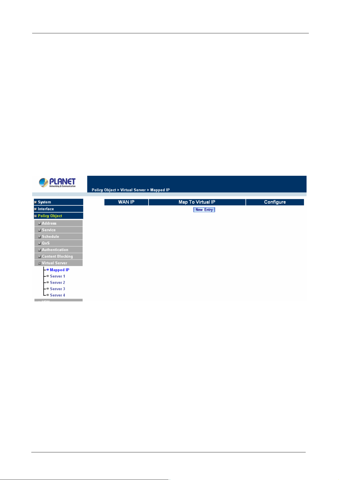
Multi-Homing Security Gateway User’s Manual
3.3.7.1 Mapped IP
Internal private IP addresses are translated through NAT (Network Address Translation). If a server is located
in the LAN network, it has a private IP address, and outside users cannot connect directly to LAN servers’
private IP address. To connect to a LAN network server, outside users have to first connect to a real IP
address of the WAN network, and the real IP is translated to a private IP of the LAN network. Mapped IP and
Virtual Server are the two methods to translate the real IP into private IP. Mapped IP maps IP in one-to-one
fashion; that means, all services of one real WAN IP address is mapped to one private LAN IP address.
Entering the Mapped IP window
Step 1. Click Mapped IP under the Virtual Server menu bar and the Mapped IP configuration window
will appear.
ÍÍ
Definition:
WAN IP: WAN IP Address.
Map to Virtual IP: The IP address which WAN maps to the virtual network in the server.
Configure: To change the setting, click Configure to modify the parameters; click delete to delete the setting.
Adding a new IP Mapping
Step 1. In the Mapped IP window, click the New Entry button. The Add New Mapped IP window will
appear.
WAN IP: select the WAN public IP address to be mapped.
Map to Virtual IP: enter the LAN private IP address will be mapped 1-to-1 to the WAN IP
address.
Step 2. Click OK to add new IP Mapping or click Cancel to cancel adding.
- 82 -
Page 89

Multi-Homing Security Gateway User’s Manual
Modifying a Mapped IP
Step 1. In the Mapped IP table, locate the Mapped IP you want to be modified and click its
corresponding Modify option in the Configure field.
Step 2. Enter settings in the Modify Mapped IP window.
Step 3. Click OK to save change or click Cancel to cancel.
NOTE: A Mapped IP cannot be modified if it has been assigned/used as a destination address of any
Incoming policies.
Removing a Mapped IP
Step 1. In the Mapped IP table, locate the Mapped IP desired to be removed and click its corresponding
Remove option in the Configure field.
Step 2. In the Remove confirmation pop-up window, click OK to remove the Mapped IP or click Cancel
to cancel.
- 83 -
Page 90
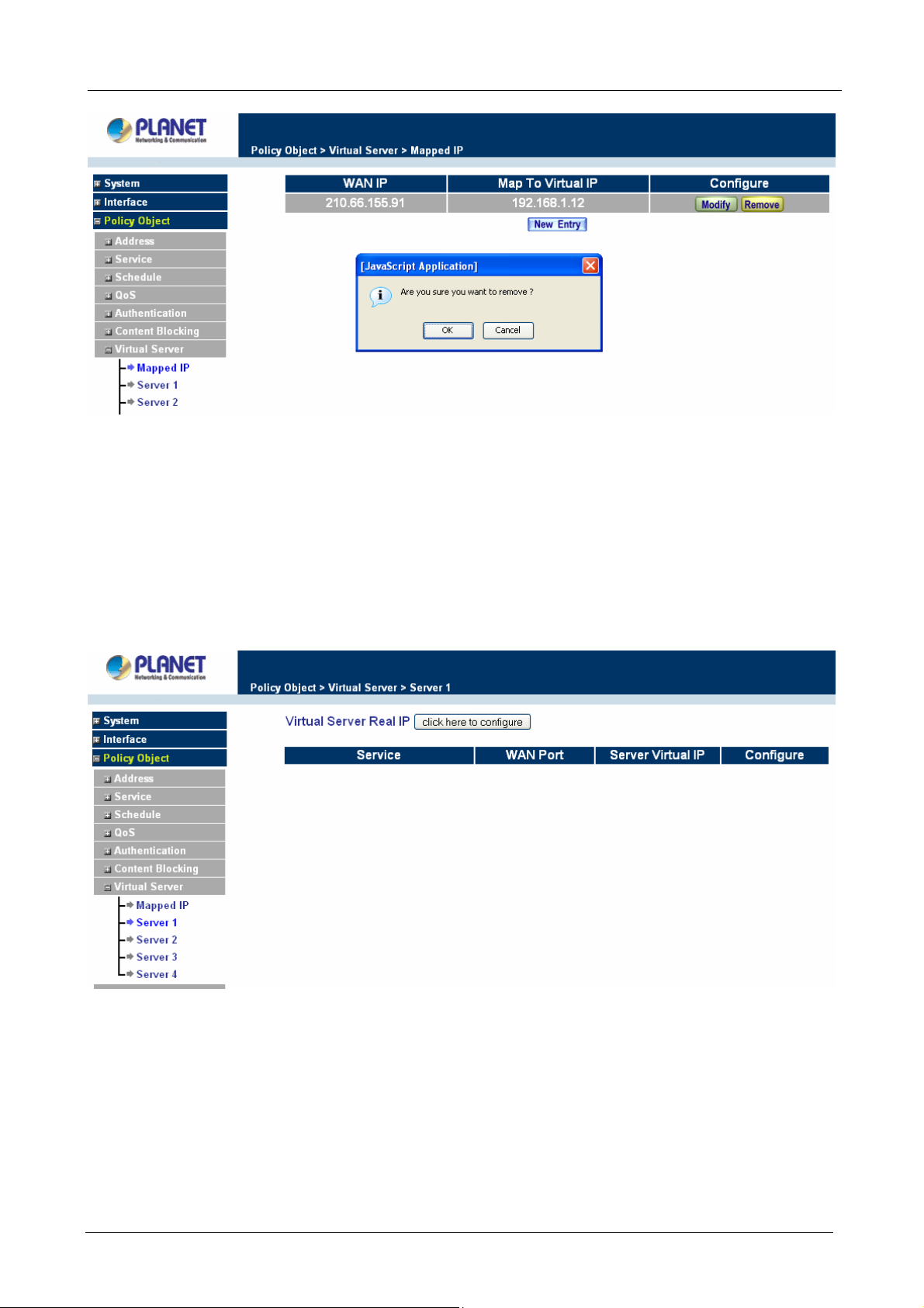
Multi-Homing Security Gateway User’s Manual
3.3.7.2 Virtual Server
Virtual server is a one-to-many mapping technique, which maps a real IP address from the WAN interface to
private IP addresses of the LAN network. This function provides services or applications defined in the
Service menu to enter into the LAN network. Unlike a mapped IP which binds a WAN IP to a LAN IP, virtual
server binds WAN IP ports to LAN IP ports.
ÍÍ
Definition:
Virtual Server Real IP: The WAN IP address configured by the virtual server. Click “Click here to configur e”
button to add a real IP address.
Service: The service name that provided by the virtual server.
WAN Port: The TCP/UDP ports that present the service items provided by the virtual server.
Server Virtual IP: The virtual IP which mapped by the virtual server.
- 84 -
Page 91

Multi-Homing Security Gateway User’s Manual
Configure: To change the service configuration, click Configure to change the parameters; click Delete to
delete the configuration.
This virtual server provides four real IP addresses, which means you can setup four virtual servers at most.
The administrator can select Virtual Server1/2/3/4 under Virtual Server selection in the menu bar on the left
hand side, click Server Virtual IP to add or change the virtual server IP address; click “Click here to
configure” to add or change the virtual server service configuration.
Configuring a Real IP for a Virtual Server
Step 1. Click an available virtual server from Server 1/2/3/4 in the Virtual Server menu bar to enter the
virtual server configuration window.
Step 2. Click the click here to configure button and the Add new Virtual Server IP window appears and
asks for an IP address from the WAN network.
Step 3. Select an IP address from the drop-down list of available WAN network IP addresses.
Step 4. Click OK to add new Virtual Server or click Cancel to cancel adding.
Modifying a Virtual Server IP Address
Step 1. Click the Server 1/2/3/4 to modify the configuration under the Virtual Server menu bar. A new
window appears displaying the IP address and service of the specified virtual server.
Step 2. Click on the Virtual Server’s IP Address button at the top of the screen.
Step 3. Choose a new IP address from the drop-down list.
Step 4. Click OK to save new IP address or click Cancel to discard changes.
- 85 -
Page 92
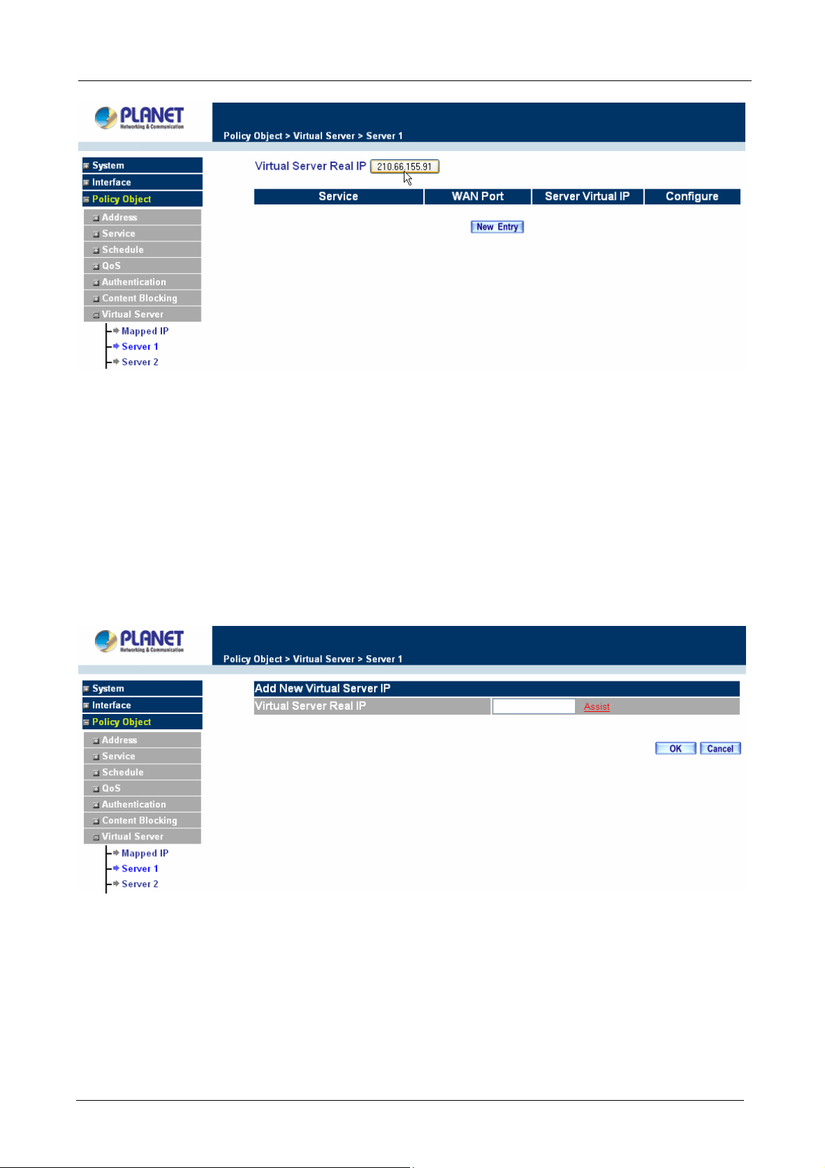
Multi-Homing Security Gateway User’s Manual
Removing a Virtual Server
Step 1. Click the virtual server to be removed in the corresponding Virtual Server option under the
Virtual Server menu bar. A new window displaying the virtual server’s IP address and service
appears on the screen.
Step 2. Click the Virtual Server’s IP Address button at the top of the screen.
Step 3. Delete the IP address.
Step 4. Click OK to remove the virtual server.
Adding New Virtual Server Service Configuration
Step 1. Select Virtual Server in the menu bar on the left hand side, and then select Server 1/2/3/4
sub-selections.
Step 2. In Server 1/2/3/4 Window, click “New Entry” button.
Step 3. Enter the parameters in the Virtual Server Configuration column.
- 86 -
Page 93
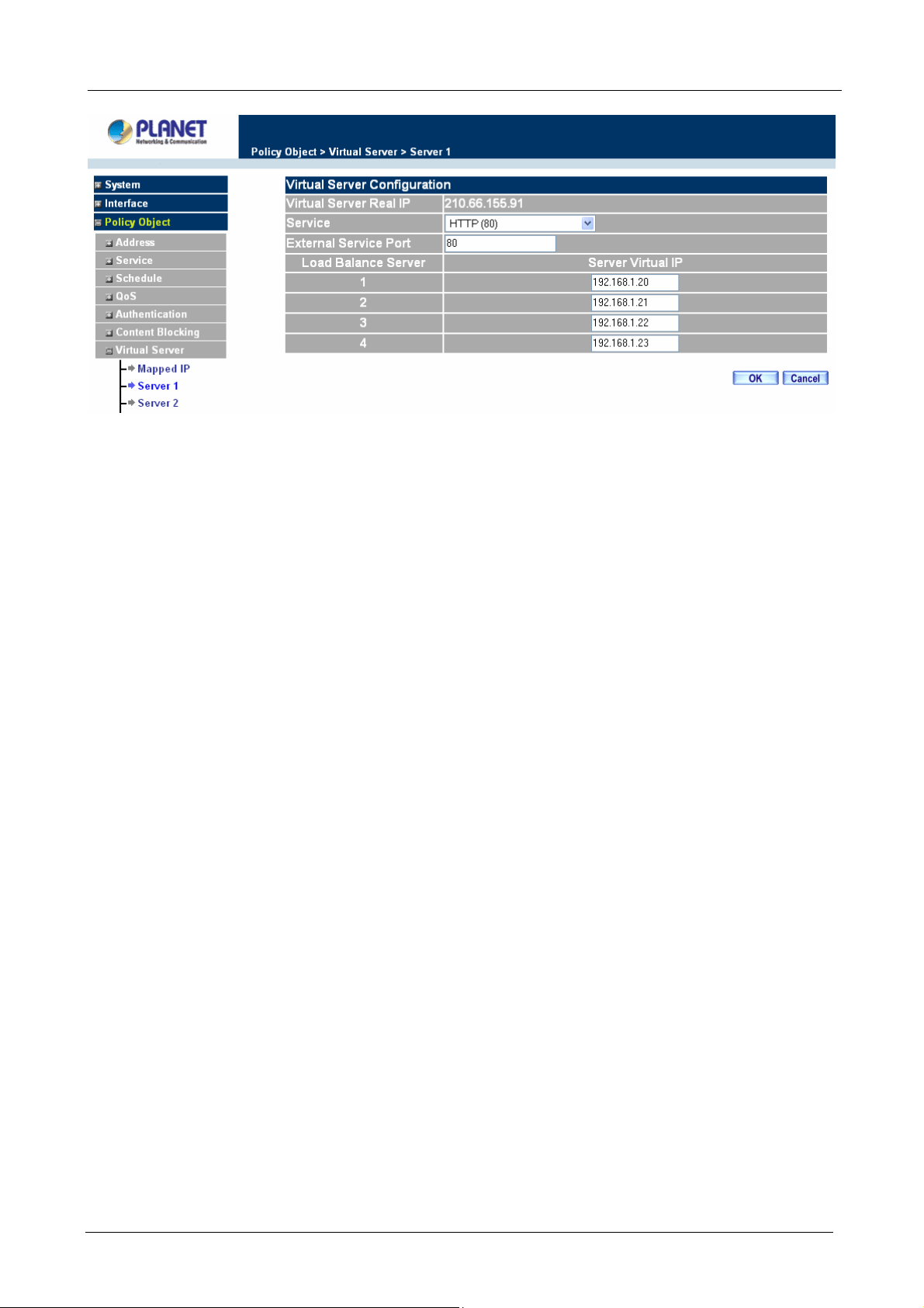
Multi-Homing Security Gateway User’s Manual
Virtual Server Real IP: displays the WAN IP address assigned to the Virtual Server
Service (Port): select the service from the pull down list that will be provided by the Real
Server (Load Balance Server).
External Service Port: Input the port number that the virtual server will use. Changing the
Service will change the port number to match the service.
Load Balance Server: The internal server IP address mapped by the virtual server. Four
computer IP addresses can be set at most, and the load can be maintained in a balance by
round robin algorithm.
Click OK to execute adding new virtual server service, or click Cancel to discard adding.
NOTE:
1. Remember to configure the service items of virtual server before you configure Policy, or the service
names will not be shown in Policy.
2. The services in the drop-down list are all defined in the Pre-defined and Custom section of the Service
menu.
Modifying the Virtual Server configurations
Step 1. In the Virtual Server window’s service table, locate the name of the service desired to be
modified and click its corresponding Modify option in the Configure field.
Step 2. In the Virtual Server Configuration window, enter the new settings.
Step 3. Click OK to save modifications or click Cancel to discard changes.
- 87 -
Page 94

Multi-Homing Security Gateway User’s Manual
Click OK to execute the change of the virtual server, or click Cancel to discard changes.
NOTE: If the destination Network in Policy has set a virtual server, it will not be able to change or configure
this virtual server, you have to remove this configuration of Policy, and then you can execute the modification
or configuration.
Removing the Virtual Server service
Step 1. In the Virtual Server window’s service table, locate the name of the service desired to be
removed and click its corresponding Remove option in the Configure field.
Step 2. In the Remove confirmation pop-up box, click OK to remove the service or click Cancel to
cancel removing.
NOTE: If the destination Network in Policy has set a virtual server, it will not be able to change or configure
this virtual server unless you have already removed this configuration of Policy.
- 88 -
Page 95

Multi-Homing Security Gateway User’s Manual
3.3.8 VPN
The CS-1000 adopts VPN to set up safe and private network service, and combine the remote Authentication
system in order to integrate the remote network and PC of the enterprise. It also provides the remote users a
safe encryption way to have best efficiency and encryption when delivering data. CS-1000 provides two kinds
of VPN service and the PPTP client.
IPSec Autokey: The system manager can create a VPN connection using Autokey IKE. Autokey IKE
(Internet Key Exchange) provides a standard method to negotiate keys between two security gateways. It
also can set up IPSec Lifetime and Preshared Key of the CS-1000.
PPTP Server: The System Manager can set up VPN-PPTP Server functions at CS-1000 in this chapter.
PPTP Client: The System Manager can set up VPN-PPTP Client functions at CS-1000 in this chapter.
Trunk: To define local and remote VPN device with related information, it also can be configured to enable
VPN Trunk function. Trunk entry must be selected in Policy to submit the further function to the VPN traffic.
What is New?
CS-1000 isolates the Trunk setting in order to allow Policy rule controlling VPN traffic. So user can filter the
VPN packets with QoS, IDP rule, and record the connection in Traffic Log or Statistic. Hence, to set up a
Virtual Private Network (VPN), you need to configure CS-1000 with following setting:
1. Configure IPSec Autokey for the encryption and authentication or PPTP Server/Client setting.
2. Configure Trunk for the information of local and remote VPN device.
3. Configure Policy rule to combine VPN traffic with QoS, IDP and the other function.
3.3.8.1 IPSec Autokey
This chapter describes steps to create a VPN connection using Autokey IKE. Autokey IKE (Internet Key
Exchange) provides a standard method to negotiate keys between two security gateways. For example, with
two Multi-Homing Security Gateway devices, IKE allows new keys to be generated after a set amount of time
has passed or a certain threshold of traffic has been exchanged.
Accessing the Autokey IKE window
Click IPSec Autokey under the VPN menu to enter the IPSec Autokey window. The IPSec Autokey table
displays current configured VPNs.
ÍÍ
- 89 -
Page 96
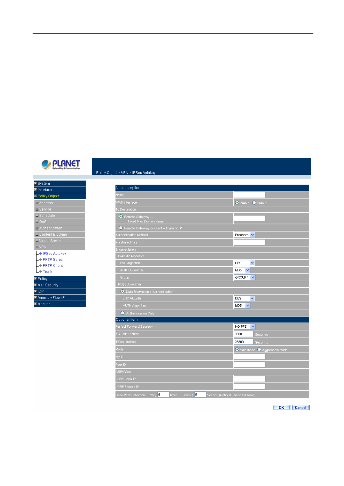
Multi-Homing Security Gateway User’s Manual
The fields in the IPSec Autokey window are:
Name: The VPN name to identify the VPN tunnel definition. The name must be different with Trunk name
and the other IPSec rule name.
WAN: The specific WAN port to be configured as VPN tunnel.
Gateway IP: The other side WAN interface IP address of VPN Gateway.
IPSec Algorithm: The display the Algorithm way.
Configure: Modify and Delete.
Adding the Autokey IKE
Step 1: Click the New Entry button and the IPSec Autokey window will appear. It divides into two parts of the
setting, Necessary Item and Optional Item.
Step 2: Configure Necessary Item paremeters.
Name: Specify a name for the VPN rule.
- 90 -
Page 97

Multi-Homing Security Gateway User’s Manual
WAN interface: Select WAN 1 or WAN 2 to be the WAN port of VPN connection.
To Destination:
Remote Gateway – Fixed IP or Domain Name: Specify the fixed IP address or domain name of the
remote side VPN gateway.
Remote Gateway or Client – Dynamic IP: Select Remote Gateway or Client if there is only one user
or device in remote site and dials up to Internet with PPPoE or cable
modem.
Preshared Key: The IKE VPN must be defined with a Preshared Key.
Encapsulation
ISAKMP Algorithm
ENC Algorithm: ESP (Encapsulating Security Payload) provides security for the payload (data)
sent through the VPN tunnel. Generally, you will want to enable both Encryption and Authentication.
The available encryption algorithms including: 56 bit DES-CBC, 168-bit 3DES-CBC, AES 128-bit,
AES 192-bit or AES 256-bit encryption algorithm. The default algorithm 56 bit DES-CBC.
AUTH Method: Authentication Method. Selects MD5 (128-bit hash) or SHA-1 (160-bit hash)
authentication algorithm. In general, SHA-1 is more secured than MD5. The default algorithm is MD5.
Group: Selects Group 1 (768-bit modulus), Group 2 (1024-bit modulus) or Group 5 (1536-bit
modulus). The larger the modulus, the more secure the generated key is. However, the larger the
modulus, the longer the key generation process takes. Both side of VPN tunnels must agree to
use the same group. The default algorithm is Group 1.
IPSec Algorithm: Select Data Encryption + Authentication or Authentication Only.
Data Encryption + Authentication
Encryption Algorithm: Selects 56 bit DES-CBC, 168-bit 3DES-CBC, AES 128-bit, AES 192-bit or
AES 256-bit encryption algorithm. The default algorithm is 56 bit DES-CBC.
Authentication Algorithm: Selects MD5 (128-bit hash) or SHA-1 (160-bit hash) authentication
algorithm. In general, SHA-1 is more secured than MD5. The default algorithm is MD5.
Authentication Only: Select this function the IPSec Algorithm will only be anthenticated with preshared
key.
Step 3: Configure Optional Item paremeters if necessary.
Perfect Forward Secrecy: Select Group 1, Group 2 or Group 5 to enhances security by changing the
IPsec key at regular intervals, and ensuring that each key has no relationship to the previous key. The
default is NO-PFS.
ISAKMP Lifetime: New keys will be generated whenever the lifetime of the old keys is exceeded. The
Administrator may enable this feature if needed and enter the lifetime in seconds to re-key. The default is
3600 seconds (one hours). Selection of small values could lead to frequent re-keying, which could affect
performance.
- 91 -
Page 98
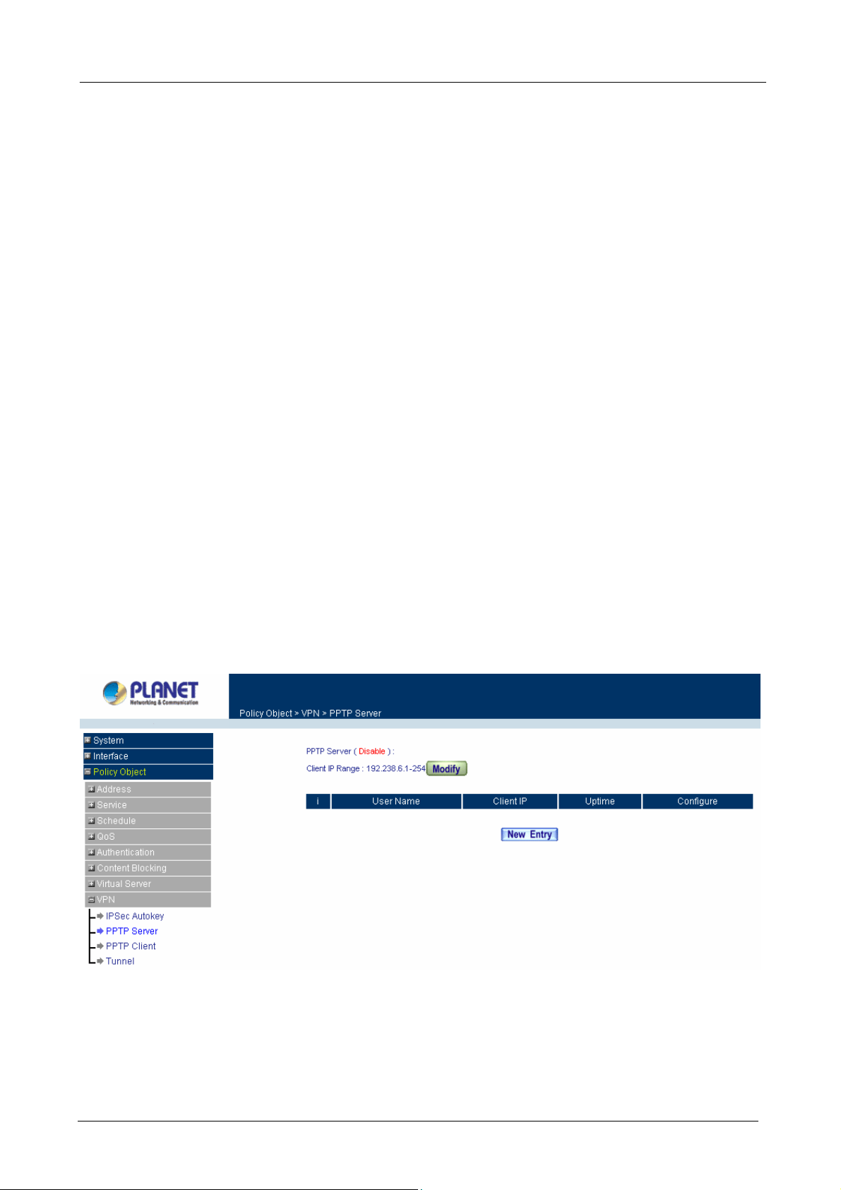
Multi-Homing Security Gateway User’s Manual
IPSec Lifetime: New keys will be generated whenever the lifetime of the old keys is exceeded. The
Administrator may enable this feature if needed and enter the lifetime in seconds to re-key. The default is
28800 seconds (eight hours). Selection of small values could lead to frequent re-keying, which could affect
performance.
Mode: Select Main mode or Aggressive mode algorithm.
My ID/Peer ID: My ID and Peer ID are optional parameters. If we choose to enter My ID/ Peer ID, they
couldn’t be the same. For instance, My ID is 11.11.11.11 and Peer ID is 22.22.22.22. If you want to use
number or text, add @ in the front, for instance, @123A and @abcd123.
GRE/IPSec: Select GRE/IPSec (Generic Routing Encapsulation) packet seal technology. You may enter
IP to be identified for both VPN gateways. The GRE/IPsec IP address can not set as the same as
CS-1000’s WAN or LAN IP subnet.
Dead Peer Detection Retry □ times Timeout □ Second: CS-1000 will check the VPN tunnel status
according to this configuration, when CS-1000 does not receive the response, it will stops the VPN
connection and keep detecting the VPN status in order to revive the VPN connection. Retry 0 times means
to disable the function.
For the complete VPN setting, you can refer to the example for more detail information.
3.3.8.2 PPTP Server
This function allows the remote client dialup to your local network and access local resources by PPTP (Point
to Point Tunnel Protocol) client software.
Entering the PPTP Server window: Select VPN→PPTP Server.
ÍÍ
PPTP Server:Click Modify to select Enable or Disable.
Client IP Range: Display the IP addresses range for PPTP Client connection.
User Name:Displays the PPTP Client user’s name for authentication.
Client IP:Displays the PPTP Client’s IP address for authentication.
- 92 -
Page 99

Multi-Homing Security Gateway User’s Manual
Uptime:Displays the connection time between PPTP Server and Client.
Configure:Click Modify to modify the PPTP Client settings or click Remove to remove the
item.
Modifying PPTP Server Design
Step 1. Select VPN→PPTP Server.
Step 2. Click Modify after the Client IP Range.
Step 3. In the Modify Server Design Window, enter appropriate settings.
Disable PPTP: Check to disable PPTP Server.
Enable PPTP: Check to enable PPTP Server.
Encryption: the default is set to disabled.
Client IP Range: Enter the IP range allocated for PPTP Clients when they connect to
the PPTP server.
Allow remote client to connect to Internet: Check to allow remote PPTP client accessing
Internet via PPTP tunnel.
Auto-Disconnect if idle □ minutes: Configure this device to disconnect to the PPTP
Server when there is no activity for a predetermined period of time. To keep the line always
connected, set the number to 0.
Echo-Request Retry □ times Timeout □ Second: CS-1000 will check the VPN
tunnel status according to this configuration, when CS-1000 does not receive the response,
it will stops the VPN connection and keep detecting the VPN status in order to revive the
VPN connection. Retry 0 times means to disable the function.
Step 4. Click OK to save modifications or click Cancel to cancel modifications
Adding PPTP Server
- 93 -
Page 100

Multi-Homing Security Gateway User’s Manual
Step 1. Select VPN→PPTP Server. Click New Entry.
Step 2. Enter appropriate settings in the following window.
User name: Specify the PPTP client. This should be unique.
Password: Specify the PPTP client password.
Client IP assigned by:
1. IP Range: check to enable auto-allocating IP for PPTP client to connect.
2. Fixed IP: check and enter a fixed IP for PPTP client to connect.
Step 3. Click OK to save modifications or click Cancel to cancel modifications.
Modifying PPTP Server
Step 1. Select VPN→PPTP Server.
Step 2. In the PPTP Server window, find the PPTP server that you want to modify. Click Configure and
click Modify.
Step 3. Enter appropriate settings.
- 94 -
 Loading...