

Page 1

Vandalproof Dome Camera
CAM-IVP55 / CAM-IVP55V
Quick Installation Guide
Page 2

Table of Contents
Safety Precautions ................................................................4
Chapter 1. Product Introduction
1.1 Before Installation ......................................................6
1.2 ProductSpecications .................................................7
Chapter 2. Physical Description and Installation
2.1 25-Meter Infrared Vari-Focal Vandalproof Camera ..........9
2.1.1 Package Content............................................. 9
2.1.2 Physical Details ..............................................9
2.1.3 Installation and Operation .............................10
2.2 25-Meter Infrared Vandalproof Camera ....................... 11
2.2.1 Package Content........................................... 11
2.2.2 Physical Details ............................................ 12
2.2.3 Installation and Operation .............................13
Chapter 3. Vari-Focal & 3-Axis Adjustment
.............................................6
.......................9
............................ 15
Page 3

Chapter 4. Operation - OSD Framework ............................... 17
4.1 OSD Button Instruction ............................................. 17
4.2 Main Menu Display ...................................................18
4.3 OSD Main Menu Description ...................................... 19
4.3.1 LENS: MANUAL / AUTO selectable. ................. 19
4.3.2 SHUTTER/AGC: AUTO / MANUAL selectable. .... 19
4.3.3 WHITE BAL. .................................................20
4.3.4 BACKLIGHT: BLC / HLC / OFF selectable. ........22
4.3.5 ATR: ON / OFF selectable. ............................. 22
4.3.6 NR ..............................................................22
4.3.7 PICT ADJUST: .............................................. 23
4.3.8 NEXT : ..........................................................23
4.3.9 EXIT : ...........................................................23
4.3.10 SAVE ALL: ................................................... 23
4.3.11 DAY/NIGHT: AUTO / DAY / NIGHT / EXT / EXT2
selectable. ...................................................23
4.3.12 PRIVACY: ON / OFF selectable. ......................25
4.3.13 MOTION: ON / OFF selectable. ...................... 26
4.3.14 CAMERA ID: ON / OFF selectable. .................. 27
4.3.15 LANGUAGE ...................................................28
4.3.16 CAMERA RESET ............................................28
4.3.17 BACK ...........................................................28
Page 4
Safety Precautions
CAUTION
RISK OF ELECTRIC SHOCK.
DO NOT OPEN!
CAUTION :
TO REDUCE THE RISK OF ELECTRICAL SHOCK,
DO NOT OPEN COVERS (OR BACK).
NO USER SERVICEABLE PARTS INSIDE.
REFER SERVICING TO QUALIFIED
SERVICE PERSONNEL.
It is advised to read the Safety Precaution Guide through
carefully before operating the product to prevent any
possible danger.
WARNING: Alert the user to the presence of un-insulated
“dangerous voltage”.
CAUTION: Alert the user to the presence of important
operating and maintenance (servicing)
instructions in the literature accompanying the
appliance.
Disposal of Old Electrical & Electronic Equipment
(Applicable in the European Union and other
European countries with separate collection
systems).
This symbol indicates that this product shall not be
treated as household waste. Instead it shall be handed
over to the applicable collection point for the recycling
of electrical and electronic equipment. By ensuring this
product is disposed of correctly, you will help prevent
potential negative consequences for the environment
and human health. For more detailed information about
recycling of this product, please contact your local city
ofce, your household waste disposal service or the shop
where you purchased the product.
Please be extra careful not to shake the product.
Page 5

Please avoid places where there are frequent vibrations
or shocks.
Do not install the product in extreme temperature
conditions.
Only use the camera under conditions where temperatures are
between -10°C and +50°C. Be especially careful to provide
ventilation when operating under high temperatures.
Do not install the product in an environment where
the humidity is high unless the product is waterproof or
weatherproof; otherwise, it can cause the image quality to be
poor.
Do not expose to strong light (sun rays), as color lters
will be discolored.
Do not spill liquid of any kind on the product.
If it gets wet, wipe it dry immediately. Alcohol or beverage can
contain minerals that corrode the electronic components.
When something abnormal occurs, make sure to unplug the
unit, and contact your local dealer .
Page 6

Chapter 1. Product Introduction
PLANET provides various camera solutions for users to solve
different security issues. The CAM-IVP55 / CAM-IVP55V, when
working with PLANET Digital Video Recorders or Internet Video
Servers, helps people easily create a secure protection system
for their daily life.
The CAM-IVP55 / CAM-IVP55V uses the latest high sensitive
color Sony Efo-E DSP EXview 1/3” interline transfer Charge
Coupled Device (CCD) image sensor, producing pictures reaching
700TV Lines of horizontal resolution, and clearer and sharper
surveillance images.
It supports Day & Night functionality, vandalproof and IP66
weatherproof features. It also initiatively provides mobile
detection warnings offering more comprehensive monitoring
of safety protection. A carefully-planned privacy zone enables
monitoring more at ease. It brings an extremely clear and
exquisite picture quality even under any challenging lighting
conditions
1.1 Before Installation
Before installation, please be sure to read this quick installation
guide carefully to complete machine installation. This guide
showshowtoquicklysetupthesecameras,unlessthespecied
term “Analog Camera” is used for these two models.
6
Page 7

1.2 ProductSpecications
Product CAM-IVP55V CAM-IVP55
Camera
Image pick-up
device
Lens
Aperture Range F1.2~2.6 F2.0
Focal Length
Iris Control Auto Fixed
Video
Min. Illuminator
Electronic Shutter
Effective Pixels
Horizontal
Resolution
Gamma
Characteristic
S/N Ratio More than 50 dB
1/3”ColorSonyEfo-EDSPEXviewHAD
CCD II
Vari-Focal Lens
2.8~10.5mm
Wide: 99.5° x 73.2°
T ele: 27.4° x 20.6°
0.01 Lux (@F1.2)
color mode
Auto:
1/50~1/100,000
Manual: 1/50(60),
1/100(120), 1/250,
1/500, 1/1000,
1/3000, 1/5000,
1/100,000
NTSC: 976 x 494
PAL: 976 x 582
Color: 650 TVL
B / W: 700 TVL
0.45
Board Lens 4.3mm
Fixed
0.01 Lux (@F1.2)
color mode
NTSC:
1/60s~1/100,000s
PAL:
1/50s~1/100,000s
7
Page 8
Function
ATW / Manual /
White Balance
On-Screen-Display
(OSD)
Gain Control Auto
IR LED 24 pieces
IR Wavelength 850 nm
IR Distance 25 meters
General
Vandalproof IK-10
Weatherproof IP-66
Synchronous
System
Video Output Composite 1.0 Vp-p, 75 ohm CVBS (BNC)
Power
Requirements
Dimensions
(Φx H)
Weight 1.1 kg
Operating
T emper ature
PUSH / ANTI CR /
USER1 / USER2 /
Push Lock
Yes No
Internal
DC 12V, 1A
IR on: 410mA
IR off: 210mA
145 x 108.2mm
-10 ~ 50 degrees C (14°F to 122°F)
Auto
8
Page 9
Chapter 2. Physical Description and
Note
12V DC
Power Input
Video
Output
Installation
2.1 25-Meter Infrared Vari-Focal Vandalproof
Camera
2.1.1 Package Content
CAM-IVP55V Camera unit x 1 l
l
Quick Installation Guide x 1
l
Screw kit x 1
l
Wrench x 1
l
Waterproof Cable Connector x 1
If any of the above items are missing, please
contact your dealer immediately.
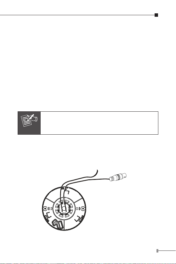
2.1.2 Physical Details
9
Page 10

Interface Description
12V DC
Power Input
Video
Output
Monitor
DVR
IVS-H125
DC power input, connect to AC power
adapter.
DC-in Jack
Note: Before plugging in the power adapter,
please ensure maximum compatibility. Using
the wrong voltage power adapter may
cause the camera to blow.
Video out
(BNC connector)
It features two bayonet lugs on the female
connector; mating is achieved with only a
quarter turn of the coupling nut.
2.1.3 Installation and Operation
Installation
1.PleasextheCAM-IVP55V tothe bracketwithscrews
2.Aftertheinstallationis nished, please placethe camerain a
suitable location.
3. Connect Video Output connector to your DVR or monitor.
4. Also you could use IVS-H125 to turn the analog camera into
IP-based surveillance.
5. Connect a DC 12V power adapter to the power Input
connector.
10
Page 11

(Connect the video-out port of the camera to a device. As
Note
the connecting method varies depending on the instrument,
therefore refer to the manual supplied with the instrument for
more information.)
Before connecting power adapter to camera,
please make sure the power output voltage is
DC 12V (max. ±10%). If you cannot be sure of
this part, we suggest you use a DC 12V switching
power adapter. It can provide stable power output.
To remove the dome cover using the provided L-shaped wrench,
loosen the screws securing the temper-resistant housing cover
(with the screws still attached on the cover) to unlock the cover
from the main body.
2.2 25-Meter Infrared Vandalproof Camera
2.2.1 Package Content
CAM-IVP55 Camera unit x 1 l
l
Quick Installation Guide x 1
l
Screw kit x 1
l
Wrench x 1
l
Waterproof Cable Connector x 1
11
Page 12

Note
If any of the above items are missing, please
12V DC
Power Input
Video
Output
contact your dealer immediately.
2.2.2 Physical Details
Interface Description
DC power input, connect to AC power
adapter.
DC-in Jack
Video out
(BNC connector)
Note: Before plugging in the power adapter,
please ensure maximum compatibility. Using
the wrong voltage power adapter may
cause the camera to blow.
It features two bayonet lugs on the female
connector; mating is achieved with only a
quarter turn of the coupling nut.
12
Page 13

Camera Lens
Tr ansparent
Dome Cover
Main Body
(Camera)
CAM-IVP55 IR Dome
2.2.3 Installation and Operation
12V DC
Power Input
Video
Output
Monitor
DVR
IVS-H125
Installation
1.PleasextheCAM-IVP55 tothe bracketwithscrews
2.Aftertheinstallationis nished, please placethe camerain a
suitable location.
3. Connect Video Output connector to your DVR or monitor.
4. Also you could use IVS-H125 to turn the analog camera into
IP-based surveillance.
13
Page 14

5. Connect a DC 12V power adapter to the Power Input
Note
connector.
(Connect the Video-out port of the camera to a device. As
the connecting method varies depending on the instrument,
therefore refer to the manual supplied with the instrument for
more information.)
Before connecting power adapter to camera,
please make sure the power output voltage is
DC 12V (max. ±10%). If you cannot be sure of
this part, we suggest you use a DC 12V switching
power adapter. It can provide stable power output.
To remove the dome cover using the provided L-shaped wrench,
loosen the screws to secure the temper-resistant housing cover
(with the screws still attached on the cover) to unlock the cover
from the main body.
14
Page 15

Chapter 3. Vari-Focal & 3-Axis Adjustment
Note
Zoom Adjustment
NEAR
TELE
WIDE
FAR
Focal Adjustment
Note
Only CAM-IVP55V has Vari-Focal.
You can adjust camera to any direction by using the Pan, Tilt,
and Rotate mechanism.
Pan Base rotates a full 360°.
Tilt Base covers a total angle of 119° (64° to one side and
55° to the other side).
Angle range of Rotate Base is 360°.
This product is not suitable for horizontal 360°
continuous rotation.
15
Page 16

Horizontal Rotation Tilt Rotation Pan Rotation
Loosen the Zoom lever counter-clockwise a little, and then
rotate the Zoom lever to obtain the best image view.
Loosen the Focus lever counter-clockwise a little, and then
rotate the Focus lever to obtain the optimum picture quality.
Re-tighten the Zoom lever and Focus lever after adjustment.
16
Page 17

Chapter 4. Operation - OSD Framework
Note
Camera Lens
Tr ansparent
Dome Cover
Main Body
(Camera)
CAM-IVP55V IR Dome
Left
Down
Enter
Up
Right
BNC
OSD Button
4.1 OSD Button Instruction
Only CAM-IVP55V has OSD function.
To adjust the OSD, remove the dome cover from the main body
by gently turning the cover counter-clockwise to unlock and pull
free from the main body. The OSD buttons can be found on the
main body of the dome camera.
After you press the button and the OSD menu comes out, you
could use the button to control the menu just like a joystick.
17
Page 18

No. Name Function
1 UP Digital Zoom-Out or Up direction button
2 DOWN Digital Zoom-In or Down direction button
3 RIGHT Increase Value (+)
4 LEFT Decrease Value (-)
5 ENTER Enter or Exit setup MENU
4.2 Main Menu Display
OSD Setup Menu page 1
LENS
SHUTTER/AGC
WHITE BAL
BACKLIGHT
ATR
NR
PICT ADJUST
NEXT (page 2)
EXIT SAVE ALL
OSD Setup Menu page 2
DAY/NIGHT
PRIVACY
MOTION DET
CAMERA ID
LANGUAGE
CAMERA RESET
BACK
EXIT SAVE ALL
AUTO
AUTO
ATW
OFF
OFF
AUTO
OFF
OFF
OFF
ENGLISH
18
Page 19

Main Menu Setup
In order to display the setup menu on the screen, set the
menu command or press the button panel.
Use UP/DOWN control buttons to select each item.
Use LEFT/RIGHT control buttons to change the data.
Use MENU control button to ENTER/EXIT the menu display.
4.3 OSD Main Menu Description
4.3.1 LENS: MANUAL / AUTO selectable.
LENS: l MAUNAL
No adjustment (Read Only)
LENS: l AUTO
TYPE: DC
AUTO
AUTO: Camera automatically controls the lens.
OPEN: Lens fully open.
CLOSE: Lens fully closed.
SPEED: Speed of the lens.
4.3.2 SHUTTER/AGC: AUTO / MANUAL selectable.
SHUTTER/AGC: l AUTO
AUTO
MODE: AUTO/OPEN/CLOSE
SPEED: 000~255
HIGH LUMINANCE
MODE: SHUT+AUTO IRIS / AUTO IRIS / SHUT
BRIGHTNESS: 000~255
LOW LUMINANCE
MODE: AGC/OFF
BRIGHTNESS: x0.25, x0.50, x0.75, x1.00
19
Page 20

HIGH LUMINANCE
When LENS is set up to AUTO mode
SHUT+AUTO IRIS: Exposure is controlled by auto electronic
shutter combined with auto iris.
AUTO IRIS: Exposure controlled by auto iris.
When LENS is set up to Manual mode
SHUT: Exposure controlled by electronic shutter.
LOW LUMINANCE
Setup low lux environment, minimum AGC level.
SHUTTER/AGC:
l MANUAL
MODE: SHUT+AGC
SHUTTER:
NTSC: 1/60, 1/100, 1/250, 1/500, 1/1000,
MANUAL
SHUTTER: Fixed electronic shutter speed.
AGC: Fixed AGC gain control.
1/2000, 1/4000, 1/10000
PAL: 1/50, 1/120, 1/250, 1/500, 1/1000,
1/2000, 1/4000, 1/10000
AGC: 6.00, 12.00, 18.00, 24.00, 30.00, 36.00,
42.00, 44.80
4.3.3 WHITE BAL.
ATW / PUSH / USER1 / USER2 / ANTI CR / MANUAL /
PUSH LOCK selectable.
20
Page 21

WHITE BAL.: l ATW
SPEED: 000~255
ATW
SPEED: ATW Speed
DELAY CNT: ATW Delay Time
ATW FRAME: ATW Frame Range Setup
ENVIRONMENT: ATW Environment Range Setup
l PUSH
WHITE BAL.:
The function will keep on detecting the Color Temperature,
and then keep saving up the parameter to the camera.
l USER1
WHITE BAL.:
DELAY CNT: 000~255
ATW FRAME: x0.50, x1.00, x1.50, x2.00
ENVIRONMENT: INDOOR, OUTDOOR
USER1
WHITE BAL.:
l USER2
USER2
WHITE BAL.:
l MANUAL
MANUAL LEVEL : 19~54
WHITE BAL.:
l ANTI CR
The function can reduce the color rolling issue, and it is the
same with CRS (Color Rolling Support) function.
l PUSH LOCK
WHITE BAL.:
The function will detect the Color Temperature to save into
the camera.
B-GAIN: 000~255
R-GAIN: 000~255
B-GAIN: 000~255
R-GAIN: 000~255
21
Page 22

4.3.4 BACKLIGHT: BLC/HLC/OFF selectable.
Note
Note
BACKLIGHT.: l BLC
Enable the function of Back Light Compensation, using BLC
Smart detection method.
l HLC
BACKLIGHT.:
Enable the function of High Light Compensation.
4.3.5 ATR: ON/OFF selectable.
ATR.: l ON
LUMINANCE LOW: MID, HIGH
CONTRAST LOW: MIDLOW, MID, MIDHIGH, HIGH
LUMINANCE: Set the extent of the luminance compression
CONTRAST: Set the extent of the contrast enhancement.
When ATR funciton has been enabled, please avoid
enabling the BACKLIGHT function at the same
time.
4.3.6 NR
NR MODE Y/C, Y, C, OFF
Y LEVEL 000~015
C LEVEL 000~015
NR MODE: Set the DNR mode of Y/C, Y and C.
Y LEVEL: Set the Ylterstrength.
C LEVEL:Setthe Clterstrength.
The Y/C mode is the automatic DNR mode.
22
Page 23

4.3.7 PICT ADJUST:
MIRROR ON/OFF
BRIGHTNESS 000~255
CONTRAST 000~255
SHARPNESS 000~255
HUE 000~255
GAIN 000~255
All camera parameters can be adjusted here.
4.3.8 NEXT:
Enter MAIN MENU, page 2.
4.3.9 EXIT:
Exit OSD to select the option list.
4.3.10 SAVE ALL:
When you change the OSD menu settings, before leaving the
OSD item option SAVE ALL. Press ENTER key to change the
memory settings for the OSD.
4.3.11 DAY/NIGHT : AUTO / DAY / NIGHT / EXT / EXT2
selectable.
DAY/NIGHT: l AUTO
BURST : ON/OFF
AUTO
BURST: Selects whether to output the burst signal when
underNight status hasbeenidentied.
DELAY CNT: 000~255
DAY: NIGHT, 000~255
NIGHT: DAY, 000~255
23
Page 24

DELAY CNT: Set the Night/Day identication transfer time
(Default: 4 sec.).
DAY NIGHT: Set the threshold for identifying the Night
status from the Day status.
NIGHT DAY: Set the threshold for identifying the Day
status from the Night status.
l DAY
DAY/NIGHT:
Day mode forcibly
DAY/NIGHT: l NIGHT
Night mode forcibly
BURST : ON/OFF
Night
BURST: Selects whether to output the burst signal.
IR OPTIMIZER:
MODE: Set the IR OPTIMIZER operating mode.
LEVEL:
l EXT1
DAY/NIGHT:
DN_IN 0[h]: Night mode
1[h]: Day mode
DAY/NIGHT: l EXT2
DN_IN 0[h]: Day mode
1[h]: Night mode
IR OPTIMIZER: ON/OFF
MODE: CENTER/AUTO
LEVEL: 00~31
The IR Optimizer function makes it
possible to minimize this overexposure by
optimizing the exposure control during Night
operations.
Adjusts the reference level of the IR Optimizer
(Default: Level 5).
24
Page 25

4.3.12 PRIVACY : ON / OFF selectable.
Note
PRIVACY: l ON
AREA SEL Max. 8
TOP 000~244 (NTSC) / 000~288(PAL)
BOTTOM 000~244 (NTSC) / 000~288(PAL)
LEFT
RIGHT
COLOR 1~8
TRANSP 0.00 / 0.50 / 0.75 / 1.00
MOSAIC ON/OFF
AREA SEL: Select the mask frame for adjustment.
TOP: Set the selected top side of the mask frame.
BOTTOM: Set the selected bottom side of the mask frame.
LEFT: Set the selected left side of the mask frame.
RIGHT: Set the selected right side of the mask frame.
COLOR: Set the selected colors of the mask frames (1~8).
TRANSP: Set the transparency ratio of the mask frames (0 /
MOSAIC: Set the mask frame mosaic function to ON or OFF.
600TVL: 000~378 (NTSC), 000~370 (PAL)
700TVL: 000~474 (NTSC), 000~468 (PAL)
600TVL: 000~378 (NTSC), 000~370 (PAL)
700TVL: 000~474 (NTSC), 000~468 (PAL)
When the MONITOR AREA has been set to ON by
the MOTION DET setting, only 4 PRIVACY AREA
SEL are selectable (1/4, 2/4, 3/4, 4/4).
0.5 / 0.75 / 1).
25
Page 26

4.3.13 MOTION: ON / OFF selectable.
MOTION DET: l ON
DETECT SENSE 000~127
BLOCK DISP ON/OFF/ENABLE
MONITOR AREA ON/OFF
AREA SEL 1~4
TOP 000~244 (NTSC) / 000~288 (PAL)
BOTTOM 000~244 (NTSC) / 000~288 (PAL)
LEFT
RIGHT
DETECT SENSE: Set the motion detection sensitivity.
BLOCK DISP:
MONITOR AREA: Set whether to use the monitoring frames.
AREA SEL: Select the monitoring frame for setup.
TOP: Set the selected top side of the monitoring frame.
BOTTOM:
LEFT: Set the selected left side of the monitoring frame.
RIGHT: Set the selected right side of the monitoring frame.
600TVL: 000~378 (NTSC), 000~370 (PAL)
700TVL: 000~474 (NTSC), 000~468 (PAL)
600TVL: 000~378 (NTSC), 000~370 (PAL)
700TVL: 000~474 (NTSC), 000~468 (PAL)
Control the ON/OFF status of the motion
detection block display.
Set the selected bottom side of the monitoring
frame.
26
Page 27

4.3.14 CAMERA ID: ON / OFF selectable.
A B C D E F G H I J K L
M N O P Q R S T U V
W X Y Z 0 1 2 3 4 5 6 7
8 9 - ! ” # $ % & ’
( ) _ ` , ¥ : ; < = > ?
@ \ ^ * . x + /
, , ,
Each User Font
The camera ID cursor moves
in the direction of the arrow
when the Enter operation input
is performed from the status
in which , , or has been
selected using the character
selection cursor.
27
Page 28

The character selected by the
camera ID cursor is cleared
CLR
POS
when the Enter operation input
is performed from the status in
which CLR has been selected
using the character selection
cursor.
The display switches to the
camera ID display position setting
screen when the Enter operation
input is performed from the
status in which POS has been
selected using the character
selection cursor. On the camera
ID display position setting screen,
the camera ID display position is
changed in real time in response
to the left, right, up or down
operation input. When the Enter
operation input is performed, the
display position is entered, and
the display returns to the camera
ID setting screen.
4.3.15 LANGUAGE
8 Selectable languages: English / Japanese / German /
French/ Russian /Portuguese /Spanish/ SimpliedChinese.
4.3.16 CAMERA RESET
Reset Factory default setup.
4.3.17 BACK
Return to MAIN MENU, page1.
28
 Loading...