

Page 1

BM-525 Bandwidth Management Gateway User’s Manual
Bandwidth Management Gateway
BM-525
User’s Manual
Page 2

BM-525 Bandwidth Management Gateway User’s Manual
Copyright
Copyright© 2006 by PLANET Technology Corp. All rights reserved. No part of this publication may be
reproduced, transmitted, transcribed, stored in a retrieval system, or translated into any language or computer
language, in any form or by any means, electronic, mechanical, magnetic, optical, chemical, manual or
otherwise, without the prior written permission of PLANET.
PLANET makes no representations or warranties, either expressed or implied, with respect to the contents
hereof and specifically disclaims any warranties, merchantability or fitness for any particular purpose. Any
software described in this manual is sold or licensed "as is". Should the programs prove defective following
their purchase, the buyer (and not this company, its distributor, or its dealer) assumes the entire cost of all
necessary servicing, repair, and any incidental or consequential damages resulting from any defect in the
software. Further, this company reserves the right to revise this publication and to make changes from time
to time in the contents hereof without obligation to notify any person of such revision or changes.
All brand and product names mentioned in this manual are trademarks and/or registered trademarks of their
respective holders.
Disclaimer
PLANET Technology does not warrant that the hardware will work properly in all environments and
applications, and makes no warranty and representation, either implied or expressed, with respect to the
quality, performance, merchantability, or fitness for a particular purpose.
PLANET has made every effort to ensure that this User’s Manual is accurate; PLANET disclaims liability
for any inaccuracies or omissions that may have occurred.
Information in this User’s Manual is subject to change without notice and does not represent a commitment
on the part of PLANET. PLANET assumes no responsibility for any inaccuracies that may be contained in
this User’s Manual. PLANET makes no commitment to update or keep current the information in this User’s
Manual, and reserves the right to make improvements to this User’s Manual and/or to the products described
in this User’s Manual, at any time without notice.
If you find information in this manual that is incorrect, misleading, or incomplete, we would appreciate your
comments and suggestions.
Trademarks
The PLANET logo is a trademark of PLANET Technology.
This documentation may refer to numerous hardware and software products by their trade names. In most, if
not all cases, these designations are claimed as trademarks or registered trademarks by their respective
companies.
CE mark Warning
This is a class B device. In a domestic environment, this product may cause radio interference, in which case
the user may be required to take adequate measures.
Federal Communication Commission Interference Statement
This equipment has been tested and found to comply with the limits for a Class B digital device, pursuant to
Part 15 of FCC Rules. These limits are designed to provide reasonable protection against harmful
interference in a residential installation. This equipment generates, uses, and can radiate radio frequency
energy and, if not installed and used in accordance with the instructions, may cause harmful interference to
radio communications. However, there is no guarantee that interference will not occur in a particular
installation. If this equipment does cause harmful interference to radio or television reception, which can
be determined by turning the equipment off and on, the user is encouraged to try to correct the interference
by one or more of the following measures:
1. Reorient or relocate the receiving antenna.
2. Increase the separation between the equipment and receiver.
3. Connect the equipment into an outlet on a circuit different from that to which the receiver is connected.
4. Consult the dealer or an experienced radio technician for help.
Page 3

BM-525 Bandwidth Management Gateway User’s Manual
FCC Caution:
To assure continued compliance (example-use only shielded interface cables when connecting to computer or
peripheral devices). Any changes or modifications not expressly approved by the party responsible for
compliance could void the user’s authority to operate the equipment.
This device complies with Part 15 of the FCC Rules. Operation is subject to the Following two conditions: (1)
This device may not cause harmful interference, and (2) this Device must accept any interference received,
including interference that may cause undesired operation.
R&TTE Compliance Statement
This equipment complies with all the requirements of DIRECTIVE 1999/5/EC OF THE EUROPEAN
PARLIAMENT AND THE COUNCIL OF 9 March 1999 on radio equipment and telecommunication
terminal Equipment and the mutual recognition of their conformity (R&TTE)
The R&TTE Directive repeals and replaces in the directive 98/13/EEC (Telecommunications Terminal
Equipment and Satellite Earth Station Equipment) As of April 8, 2000.
WEEE
To avoid the potential effects on the environment and human health as a result of the presence of
hazardous substances in electrical and electronic equipment, end users of electrical and electronic
equipment should understand the meaning of the crossed-out wheeled bin symbol. Do not dispose
of WEEE as unsorted municipal waste and have to collect such WEEE separately.
Safety
This equipment is designed with the utmost care for the safety of those who install and use it. However,
special attention must be paid to the dangers of electric shock and static electricity when working with
electrical equipment. All guidelines of this and of the computer manufacture must therefore be allowed at all
times to ensure the safe use of the equipment.
Revision
User’s Manual for Bandwidth Management Gateway
Model: BM-525
Rev: 1.0 (August, 2006)
Part No: EM-BM525v1
Page 4

BM-525 Bandwidth Management Gateway User’s Manual
Table of Contents
CHAPTER 1: INTRODUCTION..............................................................................1
FEATURES.............................................................................................................. 1
1.1
PACKAGE CONTENTS.............................................................................................2
1.2
BANDWIDTH MANAGEMENT GATEWAY TOP VIEW.................................................2
1.3
BANDWIDTH MANAGEMENT GATEWAY REAR PANEL ............................................2
1.4
SPECIFICATION ...................................................................................................... 3
1.5
CHAPTER 2: SYSTEM.............................................................................................. 4
ADMINISTRATION ..................................................................................................4
2.1
ADMIN...................................................................................................................5
2.2
PERMITTED IPS......................................................................................................8
2.3
LOGOUT ................................................................................................................ 9
2.4
SOFTWARE UPDATE .............................................................................................10
2.5
CONFIGURE ......................................................................................................... 11
2.6
SETTINGS.............................................................................................................12
2.7
DATE/TIME..........................................................................................................22
2.8
MULTIPLE SUBNET ..............................................................................................23
2.9
ROUTE TABLE....................................................................................................28
2.10
DHCP ............................................................................................................... 32
2.11
DDNS...............................................................................................................34
2.12
2.13
HOST TABLE......................................................................................................36
LANGUAGE........................................................................................................37
2.14
CHAPTER 3 INTERFACE ......................................................................................38
INTERFACE...........................................................................................................39
3.1
LAN....................................................................................................................42
3.2
WAN...................................................................................................................43
3.3
DMZ...................................................................................................................48
3.4
CHAPTER 4 POLICY OBJECT.............................................................................50
ADDRESS............................................................................................................. 50
4.1
EXAMPLE ............................................................................................................53
4.2
SERVICE...............................................................................................................60
4.3
CUSTOM ..............................................................................................................63
4.4
GROUP.................................................................................................................67
4.5
SCHEDULE...........................................................................................................70
4.6
QOS.....................................................................................................................73
4.7
Page 5

BM-525 Bandwidth Management Gateway User’s Manual
4.8 EXAMPLE ............................................................................................................77
AUTHENTICATION................................................................................................79
4.9
EXAMPLE ..........................................................................................................85
4.10
CONTENT BLOCKING .........................................................................................89
4.11
URL..................................................................................................................93
4.12
SCRIPT...............................................................................................................96
4.13
4.14
P2P ...................................................................................................................98
IM...................................................................................................................100
4.15
DOWNLOAD.....................................................................................................102
4.16
VIRTUAL SERVER.............................................................................................104
4.17
EXAMPLE ........................................................................................................108
4.18
CHAPTER 5 POLICY............................................................................................122
POLICY..............................................................................................................124
5.1
EXAMPLE ..........................................................................................................128
5.2
CHAPTER 6 ANOMALY FLOW IP.....................................................................146
SETTINGS...........................................................................................................147
6.1
CHAPTER 7 MONITOR .......................................................................................157
LOG..................................................................................................................157
7.1
TRAFFIC LOG.....................................................................................................159
7.2
EVENT LOG .......................................................................................................164
7.3
CONNECTION LOG .............................................................................................167
7.4
LOG BACKUP.....................................................................................................170
7.5
ACCOUNTING REPORT .......................................................................................172
7.6
OUTBOUND........................................................................................................175
7.7
INBOUND ...........................................................................................................181
7.8
STATISTICS.........................................................................................................187
7.9
WAN...............................................................................................................189
7.10
POLICY ............................................................................................................191
7.11
WAKE ON LAN................................................................................................ 193
7.12
STATUS ............................................................................................................195
7.13
INTERFACE.......................................................................................................196
7.14
AUTHENTICATION............................................................................................198
7.15
ARP TABLE .....................................................................................................199
7.16
DHCP CLIENTS...............................................................................................200
7.17
Page 6

BM-525 Bandwidth Management Gateway User’s Manual
Chapter 1: Introduction
The BM-525 is specifically designed for SOHO networks. It has built-in one 10/100Mbps Ethernet
LAN, DMZ, and WAN ports. No broadband router is required for users with only one public IP
address. It also supports virtual server, Multi-DMZ, and dynamic DNS functions that are very
useful for our customers to share local resources with Internet users.
For bandwidth management, packets can be classified based on IP address, IP subnet, and
TCP/UDP port number. The device has more than 40 of the most common protocols such as H.323,
Oracle, HTTP, FTP, and so on for easy definition. The administrator can then define policies to
ensure committed and maximum bandwidth levels for inbound and outbound traffic in each class.
The administrator can also define three priority levels for each policy to ensure high priority packets
receive the maximum available bandwidth. In addition, each policy can have a schedule defined for
when the policy is activated or inactivated in increments of 30 minutes.
Both the NAT mode and DMZ mode are supported, and therefore can maintain the existing network
infrastructure without reconfiguring. The BM-525 provides policy-based firewall protection and
several hacker protections to prevent hackers’ attack. Besides, the comprehensive alarm and log
function allow the network manager to easily enhance the security of local network.
1.1 Features
z One 10/100Mbps LAN, DMZ, and WAN port
z NAT mode and DMZ mode
z DMZ mode requires no changing for the original network structure
z Traffic classification based on IP, IP range/subnet, and TCP/UDP port range
z Guaranteed and maximum bandwidth with three levels of priorities
z Policy-based bandwidth management
z Assign daily and weekly access schedule to each individual policy
z Professional Monitor function includes Log, Accounting Report, Statistics, and Status
z MRTG-like Traffic Statistics, easy to trace and analyze
z Multi-Servers Load Balancing
z Dynamic DNS and DHCP server functions
z Content Filter includes URL, Script, P2P, IM, and Download blocking
z Hacker Alert and Anomaly Flow Detection
z Virtual Server and IP mapping (Multi-DMZ Host)
z Multi-language Web UI and easy to manage
z User authentication based on user name and password
- 1 -
Page 7
BM-525 Bandwidth Management Gateway User’s Manual
1.2 Package Contents
The following items should be included:
♦ Bandwidth Management Gateway
♦ Power Adapter
♦ Quick Installation Guide
♦ User’s Manual CD
If any of the contents are missing or damaged, please contact your dealer or distributor immediately.
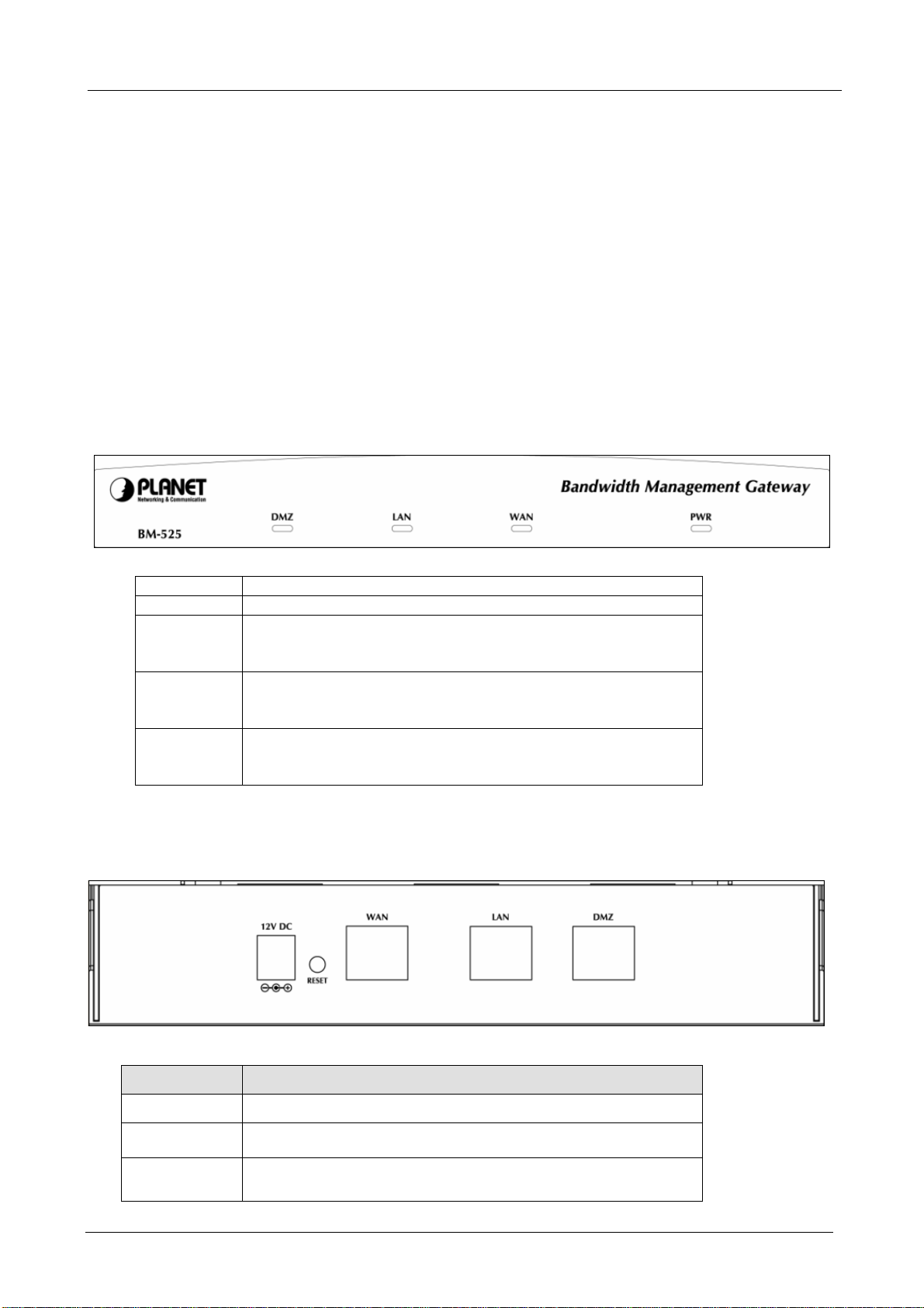
1.3 Bandwidth Management Gateway Top View
LED Description
PWR Power is supplied to this device.
WAN Steady on indicates the port is connected to other network
device.
Blink to indicates there is traffic on the port
LAN Steady on indicates the port is connected to other network
device.
Blink to indicates there is traffic on the port
DMZ Steady on indicates the port is connected to other network
device.
Blink to indicates there is traffic on the port
1.4 Bandwidth Management Gateway Rear Panel
Port or button Description
Power 12V DC, 1.5A
RESET
WAN
Press this button to restore to factory default settings.
Connect to your xDSL/Cable modem or other Internet
connection device
- 2 -
Page 8

BM-525 Bandwidth Management Gateway User’s Manual
LAN
Connect to your local PC, switch, or other local network
device
DMZ
Connect to your local PC, switch, or other local network
device
1.5 Specification
Product Bandwidth Management Gateway
Model BM-525
Hardware
WAN 1 x 10/100Base-TX Connections
LAN
DMZ
Button Reset button for hardware reset / factory default
System LED PWR, WAN, LAN, DMZ
Software
Maximum Bandwidth 25Mbps
Maximum concurrent
session
Management Web (English, Traditional Chinese, Simplified Chinese)
Operation Mode DMZ_NAT, DMZ_Transparent, NAT
WAN connection type in
NAT mode
Traffic Classification IP, IP subnet, and TCP/UDP port
Bandwidth Allocation Policy rules with Inbound/Outbound traffic management
Log Traffic Log, Event Log, Connection Log, Log backup by mail or
Statistics WAN port statistics and policy statistics with graph display
Firewall Security Policy-based access control
Hacker Alert and
Anomaly Flow Detection
Alarm Traffic alarm for user-defined traffic level
Other Functions Firmware Upgradeable through Web
1 x 10/100Base-TX, Auto-MDI/MDI-X
1 x 10/100Base-TX, Auto-MDI/MDI-X
20,000
PPPoE, DHCP, and Fixed IP
Guaranteed and maximum bandwidth
Scheduled in unit of 30 minutes
3 Priorities
syslog server
Stateful Packet Inspection (SPI)
Scheduled in unit of 30 minutes
Detect SYN Attack, Detect ICMP Flood, Detect UDP Flood,
Detect Ping of Death Attack, Detect Tear Drop Attack, Detect IP
Spoofing Attack, Filter IP Route Option, Detect Port Scan Attack,
Detect Land Attack, Virus-Infected Blocking, E-Mail Alert
Notification, NetBIOS Notification
Event alarm for hacker attack
The alarm message can sent to administrator by e-mail
NTP support
Configuration Backup and Restore through Web
Dynamic DNS support
Multiple NAT and multiple DMZ (mapped IP) support
Multiple server load balancing
- 3 -
Page 9

BM-525 Bandwidth Management Gateway User’s Manual
Chapter 2: System
2.1 Administration
“System” is the managing of settings such as the privileges of packets that pass through the
BM-525 and monitoring controls. The System Administrators can manage, monitor, and configure
BM-525 settings. But all configurations are “read-only” for all users other than the System
Administrator; those users are not able to change any setting of the BM-525.
- 4 -
Page 10

BM-525 Bandwidth Management Gateway User’s Manual
2.2 Admin
Define the required fields of Administrator
Administrator Name:
The user name of Administrators and Sub Administrator for the BM-525. The admin user
name cannot be removed; and the sub-admin user can be removed or configure.
The default Account: admin; Password: admin
Privilege:
The privileges of Administrators (Admin or Sub Admin). The user name of the main
Administrator is Administrator with reading / writing privilege. Administrator also can
change the system setting, log system status, and to increase or delete sub-administrator.
Sub-Admin may be created by the Admin by clicking
New Sub Admin
. Sub Admin have
only read and monitor privilege and cannot change any system setting value.
Configure:
Click Modify to change the “Sub-Administrator’s” password or click Remove to delete a “Sub
Administrator.”
- 5 -
Page 11
BM-525 Bandwidth Management Gateway User’s Manual
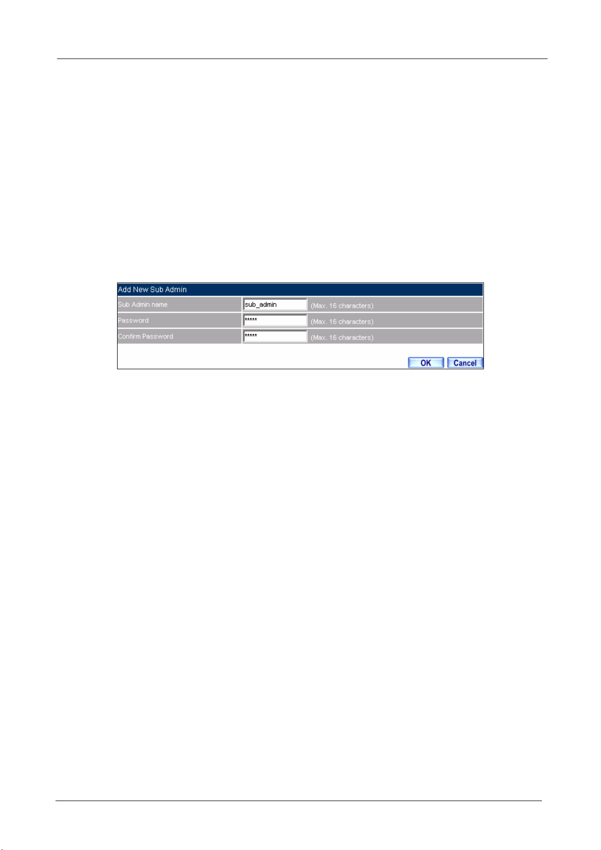
Adding a new Sub Administrator
STEP 1﹒In the Admin Web UI, click the New Sub Admin button to create a new Sub
Administrator.
STEP 2﹒In the Add New Sub Administrator Web UI and enter the following setting:
Sub Admin Name: sub_admin
Password: 12345
Confirm Password: 12345
STEP 3﹒Click OK to add the user or click Cancel to cancel it.
Add New Sub Admin
- 6 -
Page 12
BM-525 Bandwidth Management Gateway User’s Manual
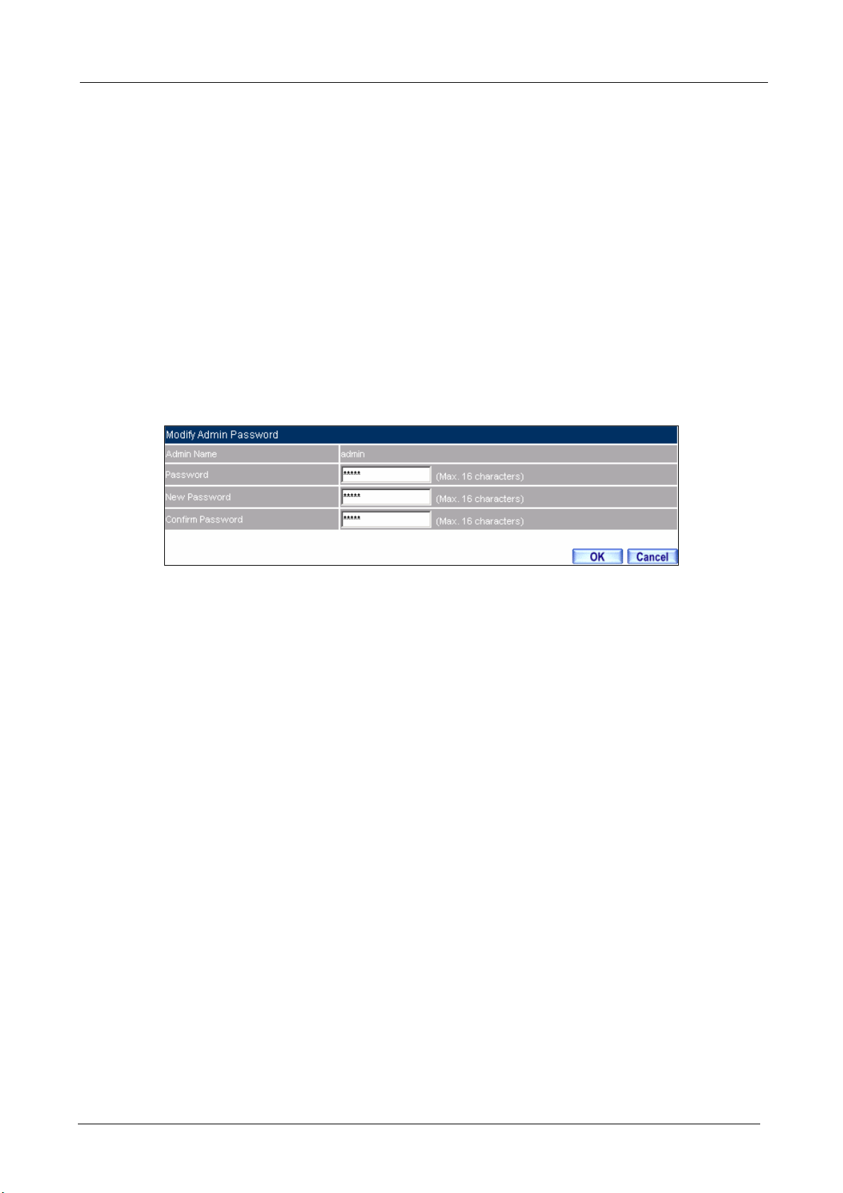
Modify the Administrator’s Password
STEP 1﹒In the Admin Web UI, locate the Administrator name you want to edit, and click on
Modify in the ConFigure field.
STEP 2﹒The Modify Administrator Password Web UI will appear. Enter the following
information:
Password: admin
New Password: 52364
Confirm Password: 52364
STEP 3﹒Click OK to confirm password change.
Modify Admin Password
- 7 -
Page 13
BM-525 Bandwidth Management Gateway User’s Manual
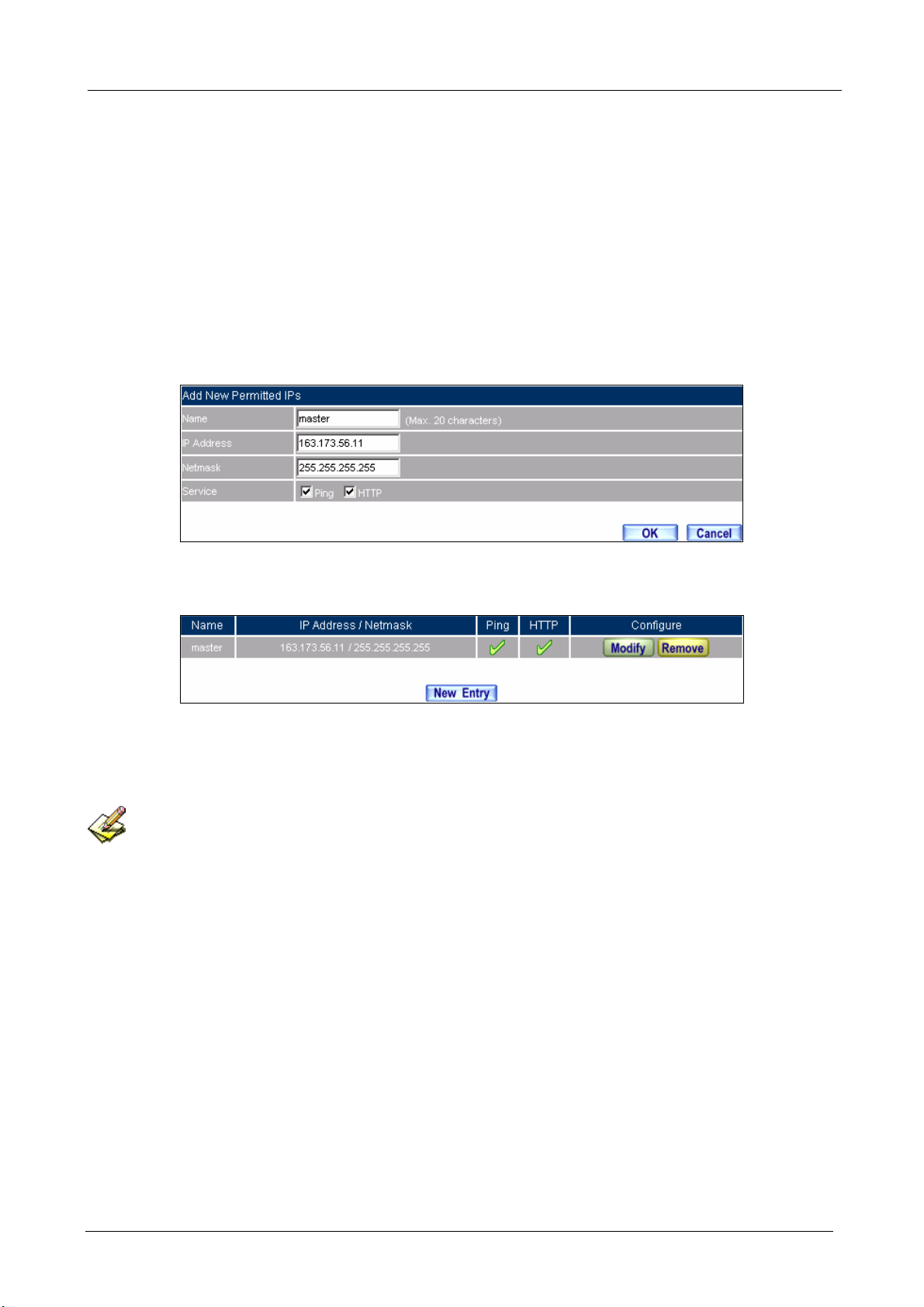
2.3 Permitted IPs
STEP 1﹒Add the following setting in Permitted IPs of Administration:
Name: Enter master
IP Address: Enter 163.173.56.11
Netmask: Enter 255.255.255.255
Service: Select Ping and HTTP
Click OK
Complete add new permitted IPs
Setting Permitted IPs Web UI
Complete Add New Permitted IPs
To make Permitted IPs be effective, it must cancel the Ping and We b UI selection in the Web UI of
BM-525 that Administrator enter. (LAN, WAN, or DMZ Interface)
Before canceling the Web U I selection of Interface, must set up the Permitted IPs first, otherwise, it wou ld
cause the situation of cannot enter Web UI by appointed Interface.
- 8 -
Page 14
BM-525 Bandwidth Management Gateway User’s Manual
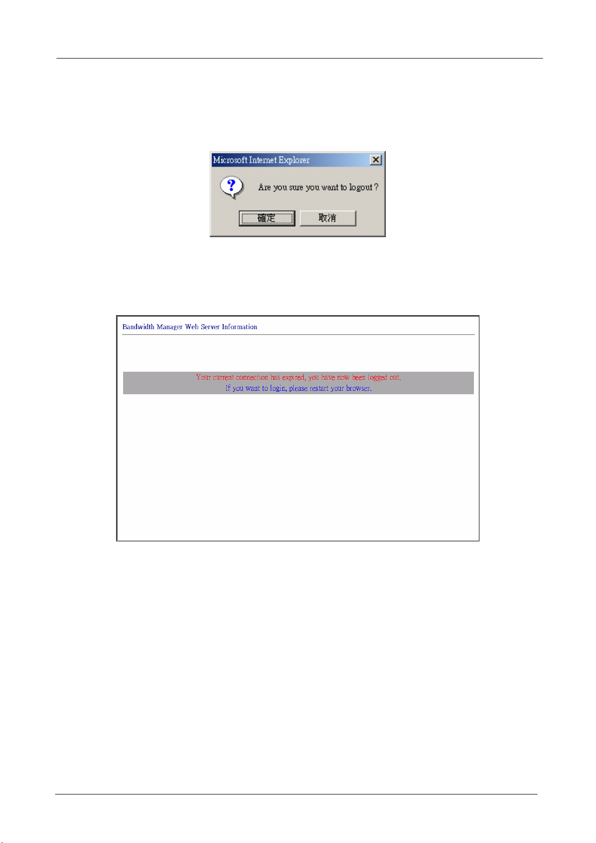
2.4 Logout
STEP 1﹒Click Logout in System to protect the system while Administrator is away.
Confirm Logout Web UI
STEP 2﹒Click OK and the logout message will appear in Web UI.
Logout Web UI Message
- 9 -
Page 15
BM-525 Bandwidth Management Gateway User’s Manual
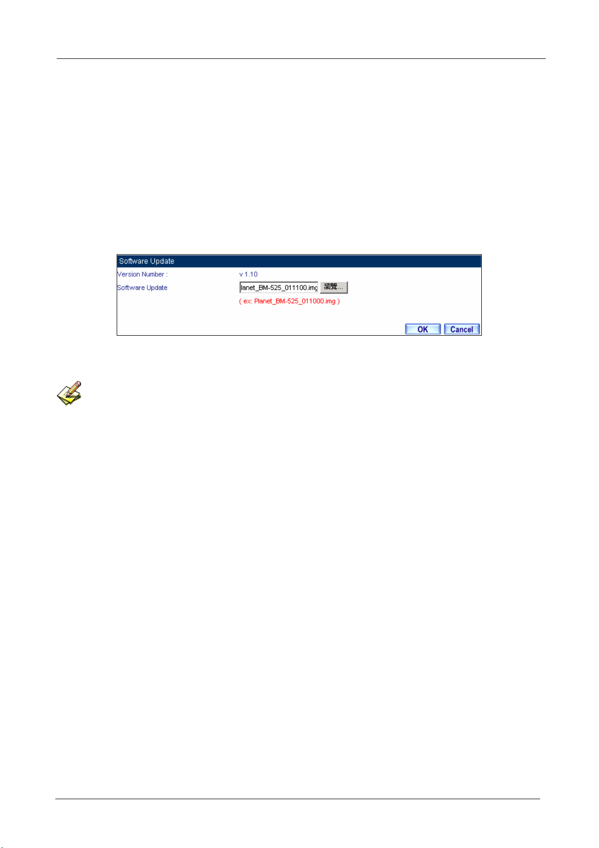
2.5 Software Update
STEP 1﹒Select Software Update in System, and follow the steps below:
To obtain the version number from Version Number and obtain the latest version
from Internet. And save the latest version in the hardware of the PC, which manage
the BM-525
Click Browse and choose the latest software version file.
Click OK and the system will update automatically.
Software Update
It takes 3 minutes to update software. The sy stem will reboot after update. During the updating time,
please don’t turn off the PC or leave the Web UI. It may cause some unexpected mistakes. (Strong suggests
updating the software from LAN to avoid unexpected mistakes.)
- 10 -
Page 16

BM-525 Bandwidth Management Gateway User’s Manual
2.6 Configure
The Configure is according to the basic setting of the BM-525. In this section the definition is
Setting, Date/Time, Multiple Subnet, Route Table, DHCP, Dynamic DNS, Hosts Table, and
Language settings.
- 11 -
Page 17

BM-525 Bandwidth Management Gateway User’s Manual
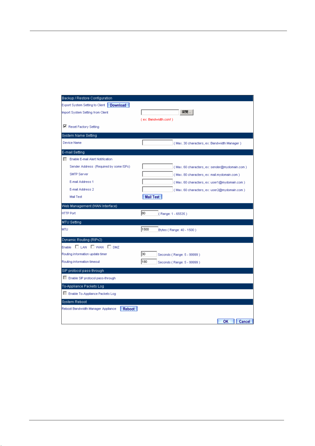
2.7 Settings
BM-525 Configuration:
The Administrator can import or export the system settings. Click OK to import the file into
the BM-525 or click Cancel to cancel importing. You also can revive to default value here.
Email Settings:
Select Enable E-mail Alert Notification under E-mail Settings. This function will enable the
BM-525 to send e-mail alerts to the System Administrator when the network is being attacked
by hackers or when emergency conditions occur. (It can be set from SettingsAnomaly Flow IP in System to detect Anomaly Flow Attacks)
Web Management (WAN Interface):
The System Manager can change the port number used by HTTP port anytime. (Remote Web
UI management)
After HTTP port has changed, if the administrator wants to enter Web UI from WAN, he will have to
change the port number of browser (For example: http://61.62.108.172:8080).
MTU Setting:
It provides the Administrator to modify the networking package length anytime. Its default
value is 1500 Bytes.
- 12 -
Page 18

BM-525 Bandwidth Management Gateway User’s Manual
Dynamic Routing (RIPv2)
By enable LAN, WAN, or DMZ Port to send and receive RIPv2 packets, the BM-525
appliance can communicate with internal or external routers and dynamically update the route
table (The MIS engineers can set up routing information update timer and routing information
timeout when it stop to receive the RIPv2 packets and the router will automatically cancel the
dynamic routing table).
SIP protocol pass-through:
When user use VoIP or Video Conference has abnormally situation, can use this function to
resolve this problem.
Administration Packet Logging:
After enable this function; the BM-525 will record packet which source IP or destination
address is BM-525. And record in Traffic Log for System Manager to inquire about.
Define the required fields of Time Settings
Synchronize Time/Date:
Synchronizing the BM-525 with the System Clock. The administrator can configure the
BM-525’s date and time by either syncing to an Internet Network Time Server (NTP) or by
syncing to your computer’s clock.
GMT:
International Standard Time (Greenwich Mean Time)
Daylight saving time setting:
When user live in the time zone implement daylight saving time, during this time unit will
adjust system time as the local time.
- 13 -
Page 19

BM-525 Bandwidth Management Gateway User’s Manual
Define the required fields of Multiple Subnet
Forwarding Mode:
To display the mode that Multiple Subnet use. (NAT mode or Routing Mode)
WAN Interface Address:
The IP address that Multiple Subnet corresponds to WAN.
LAN Interface Address/Subnet Netmask:
The Multiple Subnet range.
- 14 -
Page 20

BM-525 Bandwidth Management Gateway User’s Manual
NAT Mode:
It allows Internal Network to set multiple subnet address and connect with the Internet through
different WAN IP Addresses. For example, the lease line of a company applies several real IP
Addresses 168.85.88.0/24. The company is divided into R&D department, service, sales
department, procurement department, and accounting department. The company can
distinguish each department by different subnet for the purpose of managing conveniently. The
settings are as the following:
1. R&D department subnet:192.168.1.1/24 (LAN) ÅÆ 168.85.88.253 (WAN)
2. Service department subnet: 192.168.2.1/24 (LAN) ÅÆ 168.85.88.252 (WAN)
3. Sales department subnet: 192.168.3.1/24 (LAN) ÅÆ 168.85.88.251 (WAN)
4. Procurement department subnet
192.168.4.1/24 (LAN) ÅÆ 168.85.88.250(WAN)
5. Accounting department subnet
192.168.5.1/24 (LAN) ÅÆ 168.85.88.249(WAN)
The first department (R&D department) had set while setting interface IP; the other four ones have
to be added in Multiple Subnet. After completing the settings, each department uses the different
WAN IP Address to connect to the Internet. The settings of each department are as following:
Service Sales Procurement Accounting
IP Address 192.168.2.2~254 192.168.3.2~254 192.168.4.2~254 192.168.5.2~254
Subnet Netmask 255.255.255.0 255.255.255.0 255.255.255.0 255.255.255.0
Gateway 192.168.2.1 192.168.3.1 192.168.4.1 192.168.5.1
Routing Mode:
It is the same as NAT mode approximately but does not have to correspond to the real WAN IP
address, which let internal PC to access to Internet by its own IP (External user also can use the
IP to connect with the Internet).
- 15 -
Page 21

Define the required fields of DHCP
Subnet:
The domain name of LAN
Netmask:
The LAN Netmask
Gateway:
The default Gateway IP address of LAN
Broadcast IP:
The Broadcast IP of LAN
Define the required fields of DDNS
BM-525 Bandwidth Management Gateway User’s Manual
Domain Name:
The domain name that provided by DDNS
WAN IP Address:
The WAN IP Address, which the domain name corresponds to.
Define the required fields of Host Table
Domain Name:
It can be set by System Manager. To let the internal user to access to the information that
provided by the host by this domain name
Virtual IP Address:
The virtual IP address respective to Host Table. It must be LAN or DMZ IP address.
- 16 -
Page 22
BM-525 Bandwidth Management Gateway User’s Manual
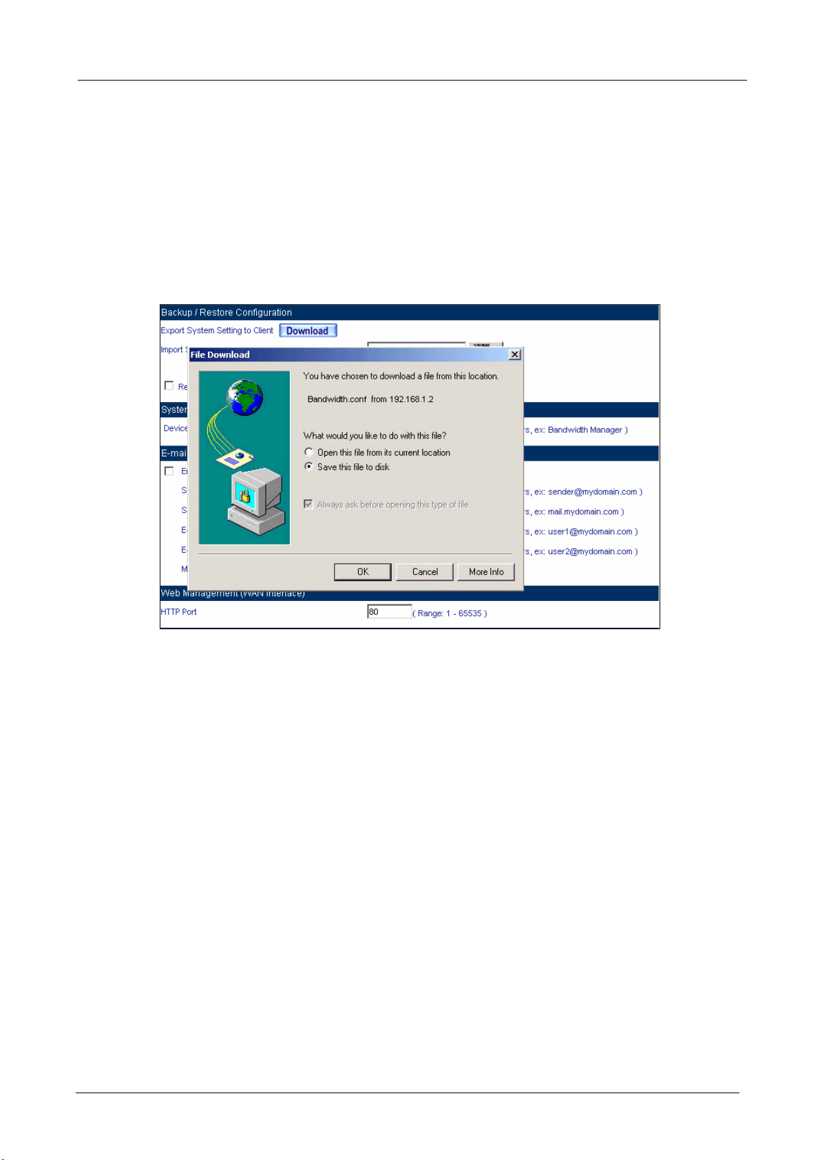
System Settings- Exporting
STEP 1﹒In System Setting Web UI, click on button next to Export System Settings to Client.
STEP 2﹒When the File Download pop-up window appears, choose the destination place where to
save the exported file and click on Save. The setting value of BM-525 will copy to the
appointed site instantly.
Select the Destination Place to Save the Exported File
- 17 -
Page 23
BM-525 Bandwidth Management Gateway User’s Manual
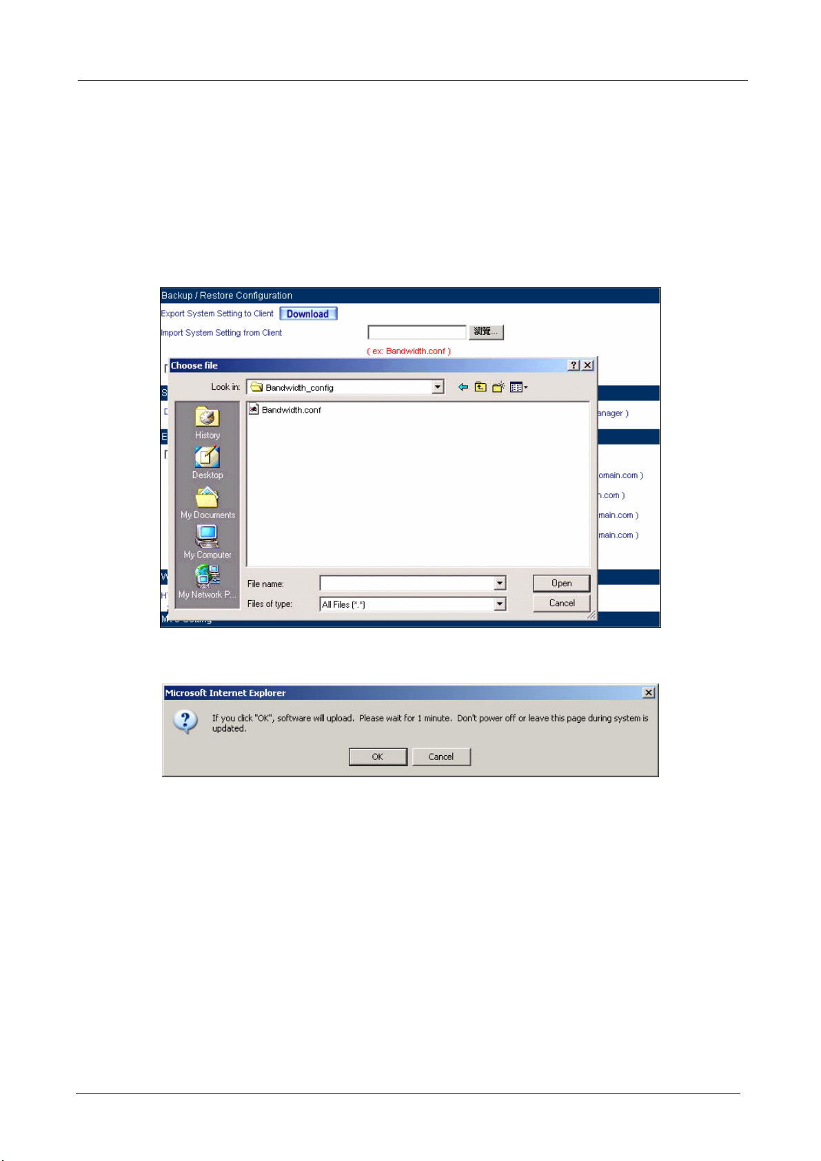
System Settings- Importing
STEP 1﹒In System Setting Web UI, click on the Browse button next to Import System Settings
from Client. When the Choose File pop-up window appears, select the file to which
contains the saved BM-525 Settings, then click OK.
STEP 2﹒Click OK to import the file into the BM-525
Enter the File Name and Destination of the Imported File
Upload the Setting File Web UI
- 18 -
Page 24
BM-525 Bandwidth Management Gateway User’s Manual
Restoring Factory Default Settings
STEP 1﹒Select Reset Factory Settings in BM-525 Configuration Web UI
STEP 2﹒Click OK at the bottom-right of the page to restore the factory settings.
Reset Factory Settings
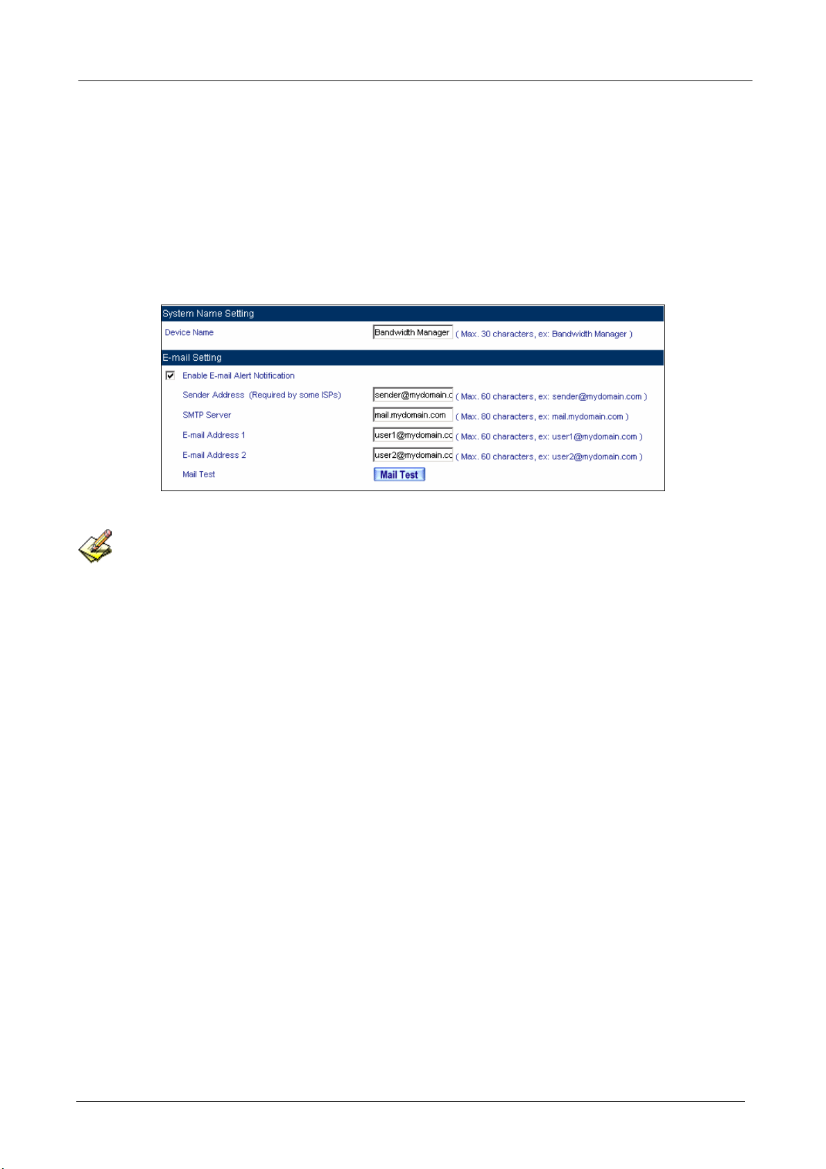
Enabling E-mail Alert Notification
STEP 1﹒Device Name: Enter the Device Name or use the default value.
STEP 2﹒Select Enable E-mail Alert Notification under E-Mail Settings.
STEP 3﹒Sender Address: Enter the Sender Address. (Required by some ISPs.)
- 19 -
Page 25
BM-525 Bandwidth Management Gateway User’s Manual
STEP 4﹒SMTP Server IP: Enter SMTP server’s IP address.
STEP 5﹒E-Mail Address 1: Enter the e-mail address of the first user to be notified.
STEP 6﹒E-Mail Address 2: Enter the e-mail address of the second user to be notified. (Optional)
STEP 7﹒Click OK on the bottom-right of the screen to enable E-mail Alert Notification.
Enable E-mail Alert Notification
Click on Mail Test to test if E-mail Address 1 and E-mail Address 2 can receive the Alert Notification
correctly.
- 20 -
Page 26
BM-525 Bandwidth Management Gateway User’s Manual
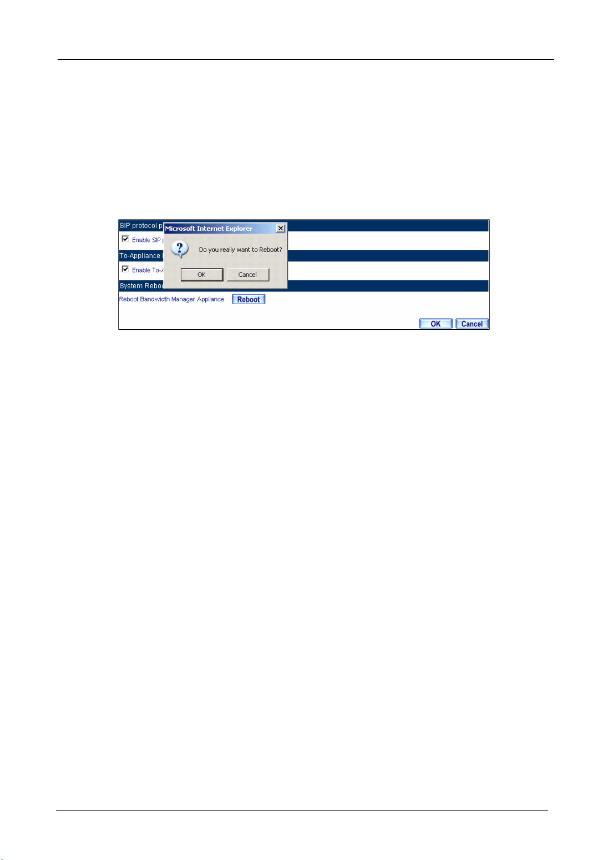
Reboot BM-525
STEP 1﹒Reboot BM-525:Click Reboot button next to Reboot BM-525 Appliance.
STEP 2﹒A confirmation pop-up page will appear.
STEP 3﹒Follow the confirmation pop-up page; click OK to restart BM-525.
Reboot BM-525
- 21 -
Page 27
BM-525 Bandwidth Management Gateway User’s Manual
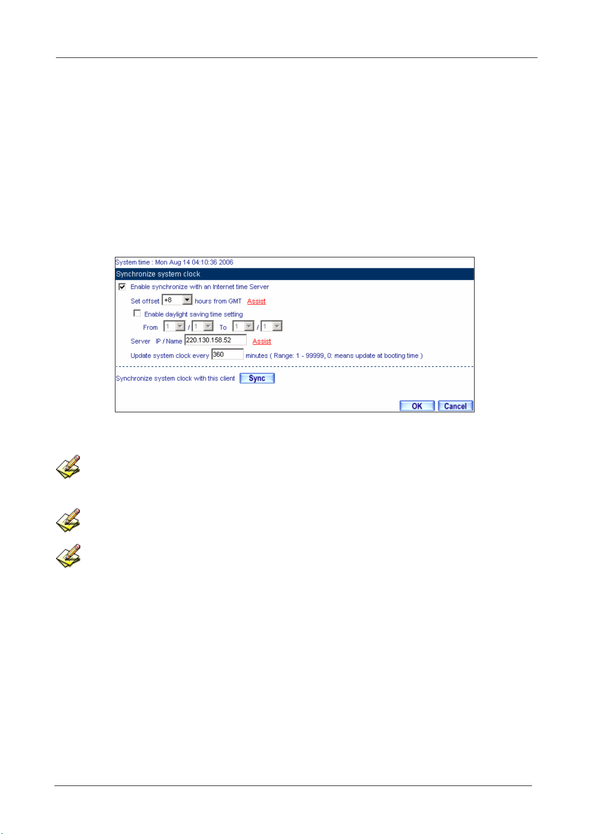
2.8 Date/Time
STEP 1﹒Select Enable synchronize with an Internet time Server.
STEP 2﹒Click the down arrow to select the offset time from GMT.
STEP 3﹒Enter the Server IP / Name with which you want to synchronize.
STEP 4﹒Set the interval time to synchronize with outside servers.
System Time Setting
Click on the Sync button and then the BM-525’s date and time will be synchronized to the
Administrator’s PC
The value of Set Offset From GMT and Server IP / Name can be looking for from Assist.
If the local area executes the daylight saving time, then enable the daylight saving time setting.
- 22 -
Page 28

BM-525 Bandwidth Management Gateway User’s Manual
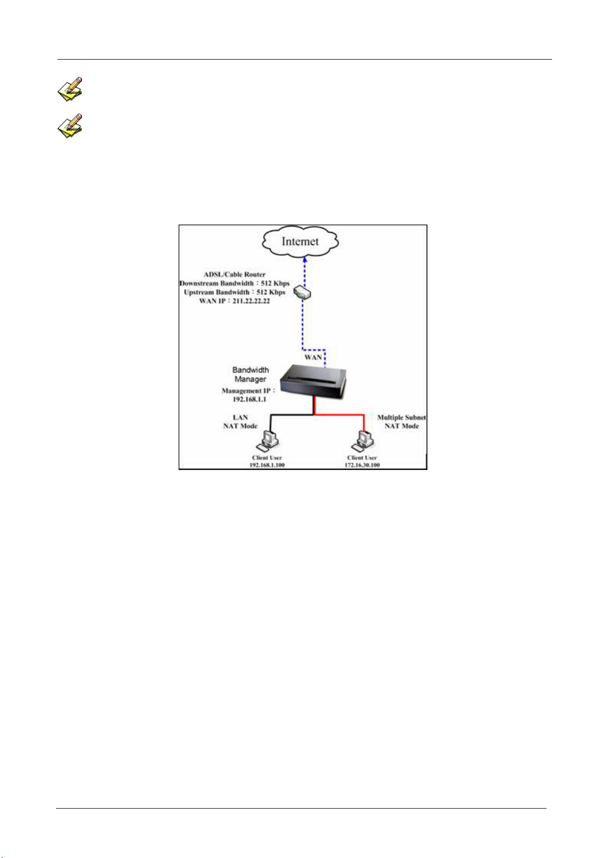
2.9 Multiple Subnet
Connect to the Internet through Multiple Subnet NAT or Routing Mode by the IP address that set by
the LAN user’s network card.
Preparation
To connect the Internet, WAN IP (211.22.22.22) connects with ATUR.
- 23 -
Page 29
BM-525 Bandwidth Management Gateway User’s Manual
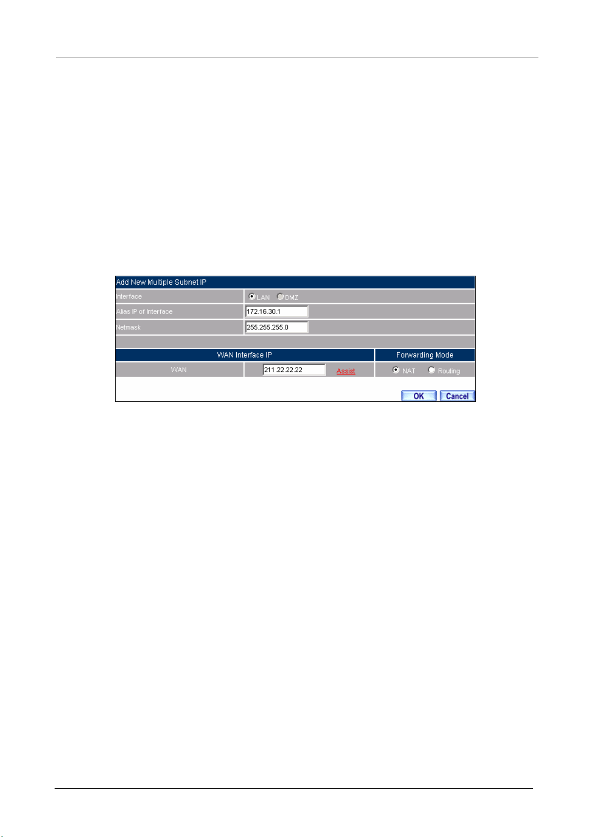
Adding Multiple Subnet
Add the following settings in Multiple Subnet of System function:
Click on New Entry
Alias IP of LAN Interface: Enter 172.16.30.1
Netmask:Enter 255.255.255.0
WAN:Enter Interface IP211.22.22.22, and choose NAT in Forwarding Mode
Click OK
Complete Adding Multiple Subnet
Add Multiple Subnet Web UI
- 24 -
Page 30
BM-525 Bandwidth Management Gateway User’s Manual
WAN Interface can use Assist to enter the data.
After setting, there will be two subnets in LAN: 192.168.1.0/24 (default LAN subnet) and
172.16.30.0/24. So if LAN IP is:
192.168.1.xx, it must use NAT Mode to connect to the Internet.
162.172.50.xx, it’s also use NAT mode through WAN (The Internet Server can see your WAN IP directly).
The BM-525’s Interface Status:
WAN IP:211.22.22.22
LAN Port IP:192.168.1.1
LAN Port Multiple Subnet:172.16.30.1
Multiple Subnet Network
- 25 -
Page 31

BM-525 Bandwidth Management Gateway User’s Manual
WAN IP (10.10.10.1) connects to the Router of ISP (10.10.10.2) directly. The IP address provided
by ISP is 162.172.50.0/24
Add the following settings in Multiple Subnet of System function:
Click on New Entry
Alias IP of LAN Interface: Enter 162.172.50.1
Netmask:Enter 255.255.255.0
WAN:Enter Interface IP: 10.10.10.1, and choose Routing in Forwarding Mode
Click OK
Complete Adding Multiple Subnet
Multiple Subnet Web UI Setting
After settin g, if LAN IP of BM-525 is 162.172.50.xx, it uses Routing Mode (Internet Server can see
your IP 162.172.50.xx directly)
- 26 -
Page 32

BM-525 Bandwidth Management Gateway User’s Manual
The BM-525’s Interface Status:
WAN IP:10.10.10.1
LAN Port IP:192.168.1.1
LAN Port Multiple Subnet:162.172.50.1
Multiple Subnet Network
- 27 -
Page 33

BM-525 Bandwidth Management Gateway User’s Manual
2.10 Route Table
To connect two different subnet router with the BM-525 and makes them to
connect to Internet through BM-525.
Preparation
Company A: WAN (61.11.11.11) connects with ATUR to Internet
LAN subnet: 192.168.1.1/24
The Router1 which connect with LAN (10.10.10.1, support RIPv2) its LAN subnet
is 192.168.10.1/24
Company B: Router2 (10.10.10.2, support RIPv2), its LAN subnet is 192.168.20.1/24
Company A‘s Router1 (10.10.10.1) connect directly with Company B‘s Router2 (10.10.10.2).
- 28 -
Page 34

BM-525 Bandwidth Management Gateway User’s Manual
STEP 1﹒Enter the following settings in Route Table in System function:
Destination IP: Enter 192.168.10.1
Netmask: Enter 255.255.255.0。
Gateway: Enter 192.168.1.252
Interface: Select LAN
Click OK
Add New Static Route1
STEP 2﹒Enter the following settings in Route Table in System function:
Destination IP: Enter 192.168.20.1
Netmask: Enter 255.255.255.0
Gateway: Enter 192.168.1.252
Interface: Select LAN
Click OK
Add New Static Route2
- 29 -
Page 35

BM-525 Bandwidth Management Gateway User’s Manual
STEP 3﹒Enter the following setting in Route Table in System function:
Destination IP: Enter 10.10.10.0
Netmask: Enter 255.255.255.0
Gateway: Enter 192.168.1.252
Interface: Select LAN
Click OK
Add New Static Route3
- 30 -
Page 36

BM-525 Bandwidth Management Gateway User’s Manual
STEP 4﹒Adding successful. At this time the computer of 192.168.10.1/24, 192.168.20.1/24 and
192.168.1.1/24 can connect with each other and connect to Internet by NAT.
Route Table Setting
- 31 -
Page 37

BM-525 Bandwidth Management Gateway User’s Manual
2.11 DHCP
STEP 1﹒Select DHCP in System and enter the following settings:
Domain Name:Enter the Domain Name
DNS Server 1: Enter the distributed IP address of DNS Server1.
DNS Server 2: Enter the distributed IP address of DNS Server2.
WINS Server 1: Enter the distributed IP address of WINS Server1.
WINS Server 2: Enter the distributed IP address of WINS Server2.
LAN Interface:
Client IP Address Range 1: Enter the starting and the ending IP address
dynamically assigning to DHCP clients. The default value is 192.168.1.2 to
192.168.1.254 (it must be in the same subnet)
Client IP Address Range 2: Enter the starting and the ending IP address
dynamically assigning to DHCP clients. But it must in the same subnet as
Client IP Address Range 1 and the range cannot be repeated.
DMZ Interface: the same as LAN Interface. (DMZ works only if to enable DMZ
Interface)
Leased Time: Enter the leased time for Dynamic IP. The default time is 24 hours.
Click OK and DHCP setting is completed.
- 32 -
Page 38

BM-525 Bandwidth Management Gateway User’s Manual
DHCP Web UI
When select ing Automatically Get DNS, the DNS Server will lock it as LAN Interface IP. (Using
Occasion: When the system Administrator starts Authentication, the users’ first DNS Server must be the
same as LAN Interface IP in order to enter Authentication Web UI)
- 33 -
Page 39

BM-525 Bandwidth Management Gateway User’s Manual
2.12 DDNS
STEP 1﹒Select Dynamic DNS in System function. Click New Entry button
Service providers:Select service providers.
Automatically fill in the WAN IP:Check to automatically fill in the WAN IP.。
User Name:Enter the registered user name.
Password:Enter the password
Domain name:Enter Your host domain name
Click OK to add Dynamic DNS.
DDNS Web UI
Complete DDNS Setting
- 34 -
Page 40

BM-525 Bandwidth Management Gateway User’s Manual
Chart
Meaning Update
successfully
Incorrect
username or
Connecting
to server
Unknown error
password
If System Administrator had not registered a DDNS account, click on Sign up then can enter the
website of the provider.
If you do not select Automatically fill in the WAN IP and then you can enter a specific IP in WAN
IP. Let DDNS to correspond to that specific IP address.
- 35 -
Page 41

BM-525 Bandwidth Management Gateway User’s Manual
2.13 Host Table
STEP 1﹒ Select Host Table in Settings function and click on New Entry
Domain Name: The domain name of the server
Virtual IP Address: The virtual IP address respective to Host Table
Click OK to add Host Table.
Add New Host Table
To use Host Table, the user PC’s first DNS Server must be the same as the LAN Port or DMZ Port IP
of BM-525. That is the default gateway.
- 36 -
Page 42

BM-525 Bandwidth Management Gateway User’s Manual
2.14 Language
Select the Language version (English Version, Traditional Chinese Version, or Simplified
Chinese Version) and click OK.
Language Setting Web UI
- 37 -
Page 43

BM-525 Bandwidth Management Gateway User’s Manual
Chapter 3 Interface
In this section, the Administrator can set up the IP addresses for the office network. The
Administrator may configure the IP addresses of the LAN network, the WAN network, and the
DMZ network. The Netmask and gateway IP addresses are also configure d in this section.
- 38 -
Page 44

BM-525 Bandwidth Management Gateway User’s Manual
3.1 Interface
Define the required fields of Interface
LAN:
Using the LAN Interface, the Administrator can set up the LAN network of BM-525.
Ping:
Select this function to allow the LAN users to ping the Interface IP Address.
HTTP:
Select to enable the user to enter the Web UI of BM-525 from Interface IP.
WAN:
The System Administrator can set up the WAN network of BM-525.
Connect Mode:
Display the current connection mode:
PPPoE (ADSL user)
Dynamic IP Address (Cable Modem User)
Static IP Address
PPTP (European User Only)
Upstream/Downstream Bandwidth:
The System Administrator can set up the correct Bandwidth of WAN network Interface here.
Auto Disconnect:
The PPPoE connection will automatically disconnect after a length of idle time (no activities).
Enter the amount of idle time before disconnection in the field. Enter “0” if you do not want
the PPPoE connection to disconnect at all.
- 39 -
Page 45

BM-525 Bandwidth Management Gateway User’s Manual
DMZ:
The Administrator uses the DMZ Interface to set up the DMZ network.
The DMZ includes:
NAT Mode:In this mode, the DMZ is an independent virtual subnet. This virtual subnet
can be set by the Administrator but cannot be the same as LAN Interface.
Transparent Mode: In this mode, the DMZ and WAN Interface are in the same subnet.
- 40 -
Page 46

BM-525 Bandwidth Management Gateway User’s Manual
We set up four Interface Address examples in this section:
No. Suitable
Situation
Ex1
Ex2
Ex3
Ex4
LAN
WAN
DMZ
DMZ
Example
Modify LAN Interface Settings
Setting WAN Interface Address
Setting DMZ Interface Address (NAT Mode)
Setting DMZ Interface Address (Transparent Mode)
- 41 -
Page 47

BM-525 Bandwidth Management Gateway User’s Manual
3.2 LAN
STEP 1﹒Select LAN in Interface and enter the following setting:
Enter the new IP Address and Netmask
Select Ping and HTTP
Click OK
Setting LAN Interface Web UI
The default LAN IP Address is 192.168.1.1. After the Administrator setting the new LAN IP Address
on the computer , he/she has to restart the System to make the new IP address effective (when the computer
obtain IP by DHCP).
Do not cancel Web UI selection before not setting Permitted IPs yet. It will cause the Administrator
cannot be allowed to enter the BM-525’s Web UI from LAN.
- 42 -
Page 48

BM-525 Bandwidth Management Gateway User’s Manual
3.3 WAN
STEP 1﹒Select WAN in Interface and click Modify
STEP 2﹒Select the Connecting way:
PPPoE (ADSL User):
1. Select PPPoE
2. Enter User Name as an account
3. Enter Password as the password
4. Select Dynamic or Fixed in IP Address provided by ISP. If you select Fixed,
please enter IP Address, Netmask, and Default Gateway.
5. Enter Max. Downstream Bandwidth and Max. Upstream Bandwidth.
(According to the flow that user apply)
6. Select Ping and Web UI
7. Click OK
PPPoE Connection
If the connection is PPPoE, you can choose Service-On-Demand for WAN Interface to connect
automatically when disconnect (suggested); or to set up Auto Disconnect if idle (not recommend)
- 43 -
Page 49

BM-525 Bandwidth Management Gateway User’s Manual
Dynamic IP Address (Cable Modem User):
1. Select Dynamic IP Address (Cable Modem User)
2. Click Renew in the right side of IP Address and then can obtain IP automatically.
3. If the MAC Address is required for ISP then click on Clone MAC Address to
obtain MAC IP automatically.
4. Hostname: Enter the hostname provided by ISP.
5. Domain Name: Enter the domain name provided by ISP.
6. User Name and Password are the IP distribution method according to
Authentication way of DHCP+ protocol (like ISP in China)
7. Enter Max. Downstream Bandwidth and Max. Upstream Bandwidth
(According to the flow that user apply)
8. Select Ping and Web UI
9. Click OK
Dynamic IP Address Connection
- 44 -
Page 50

BM-525 Bandwidth Management Gateway User’s Manual
Static IP Address
1. Select Static IP Address
2. Enter IP Addr ess, Netmask, and Default Gateway that provided by ISP
3. Enter DNS Server1 or DNS Server2
4. Enter Max. Downstream Bandwidth and Max. Upstream Bandwidth
(According to the flow that user apply)
5. Select Ping and Web UI
6.Click OK
Static IP Address Connection
When selecting Ping and We b U I on WAN network Interface, users will be able to ping the BM-525
and enter the Web UI WAN network. It may influence network security. The suggestion is to Cancel Ping
and Web UI after all the settings have finished. And if the System Administrator needs to enter UI from
WAN, he/she can use Permitted IPs to enter.
PPTP (European User Only):
1. Select PPTP (European User Only)
2. Enter the name of applied account in User Name.
3. Enter the password of applied account in Password.
4. Select Obtain an IP address automatically or Use the following IP address (use
the assigned IP address) in IP Address provided by ISP.
Select Obtain as IP address automatically, please enter the value of MAC
Address, Host Name and Domain Name.
Select Use the following IP address. Please enter the value of IP address,
- 45 -
Page 51

BM-525 Bandwidth Management Gateway User’s Manual
Netmask, and Default Gateway.
5. Enter value of PPTP Gateway. (Connect ID is required by some ISP provider).
6. Enter the value of MAX. Downstream Bandwidth and MAX. Upstream
Bandwidth (According to the applied bandwidth).
7. Select Ping and HTTP in Enable System Management.
8. Click OK.
- 46 -
Page 52

BM-525 Bandwidth Management Gateway User’s Manual
Dynamic IP Address Connection
If the connection is PPPoE, you can choose Service-On-Demand for WAN Interface to connect
automatically when disconnect (suggested); or to set up Auto Disconnect if idle (not recommend)
- 47 -
Page 53

BM-525 Bandwidth Management Gateway User’s Manual
3.4 DMZ
Setting DMZ Interface Address (NAT Mode)
STEP 1﹒Click DMZ Interface
STEP 2﹒Select NAT Mode in DMZ Interface
Select NAT in DMZ Interface
Enter IP Address and Netmask
STEP 3﹒Select Ping and HTTP
STEP 4﹒Click OK
Setting DMZ Interface Address (NAT Mode) Web UI
- 48 -
Page 54

BM-525 Bandwidth Management Gateway User’s Manual
Setting DMZ Interface Address (Transparent Mode)
STEP 1﹒Select DMZ Interface
STEP 2﹒Select Transparent Mode in DMZ Interface
Select DMZ_Transparent in DMZ Interface
STEP 1﹒Select Ping and HTTP
STEP 2﹒Click OK
Setting DMZ Interface Address (Transparent Mode) Web UI
In WAN, the connecting way must be Static IP Address and can choose Transparent Mode in DMZ.
- 49 -
Page 55

BM-525 Bandwidth Management Gateway User’s Manual
Chapter 4 Policy Object
4.1 Address
The BM-525 allows the Administrator to set Interface addresses of the LAN network, LAN network
group, WAN network, WAN network group, DMZ and DMZ group.
An IP address in the Address Table can be an address of a computer or a sub network. The
Administrator can assign an easily recognized name to an IP address. Based on the network it
belongs to, an IP address can be an LAN IP address, WAN IP address or DMZ IP address. If the
Administrator needs to create a control policy for packets of different IP addresses, he can first add
a new group in the LAN Group or the WAN Group and assign those IP addresses into the newly
created group. Using group addresses can greatly simplify the process of building control policies.
With easily recognized names of IP addresses and names of address groups shown in the address table,
the Administrator can use these names as the source address or destination address of control policies. The
address table should be setup before creating control policies, so that the Administrator can pick the names of
correct IP addresses from the address table when setting up control policies.
- 50 -
Page 56

BM-525 Bandwidth Management Gateway User’s Manual
Define the required fields of Address
Name:
The System Administrator set up a name as IP Address that is easily recognized.
IP Address:
It can be a PC’s IP Address or several IP Address of Subnet. Different network area can be:
Internal IP Address, External IP Address, and DMZ IP Address.
Netmask:
When correspond to a specific IP, it should be set as: 255.255.255.255.
When correspond to several IP of a specific Domain. Take 192.168.100.1 (C Class subnet) as
an example, it should be set as: 255.255.255.0.
MAC Address:
Correspond a specific PC’s MAC Address to its IP; it can prevent users changing IP and
accessing to the net service through policy without authorizing.
Get Static IP address from DHCP Server:
When enable this function and then the IP obtain from DHCP Server automatically under LAN
or DMZ will be distributed to the IP that correspond to the MAC Address.
- 51 -
Page 57

BM-525 Bandwidth Management Gateway User’s Manual
We set up two Address examples in this section:
No Suitable
Situation
Ex1
Ex2
LAN
LAN Group
WAN
Example
Under DHCP circumstances, assign the specific IP to
static users and restrict them to access FTP net service
only through policy.
Set up a policy that only allows partial users to connect
with specific IP (External Specific IP)
- 52 -
Page 58

BM-525 Bandwidth Management Gateway User’s Manual
4.2 Example
Under DHCP situation, assign the specific IP to static users and restrict them to
access FTP net service only through policy
STEP 1﹒Select LAN in Address and enter the following settings:
Click New Entry button
Name: Enter Rayearth
IP Address: Enter 192.168.3.2
Netmask: Enter 255.255.255.255
MAC Address : Enter the user’s MAC Address(00:B0:18:25:F5:89)
Select Get static IP address from DHCP Server
Click OK
Setting LAN Address Book Web UI
Complete the Setting of LAN
- 53 -
Page 59

BM-525 Bandwidth Management Gateway User’s Manual
STEP 2﹒Adding the following setting in Outgoing Policy:
Add a Policy of Restricting the Specific IP to Access to Internet
STEP 3﹒Complete assigning the specific IP to static users in Outgoing Policy and restrict them to
access FTP net service only through policy :
Complete the Policy of Restricting the Specific IP to Access to Internet
- 54 -
Page 60

BM-525 Bandwidth Management Gateway User’s Manual
When the System Administrator setting the Address Book, he/she can choose the way of clicking on
to make the BM-525 to fill out the user’s MAC Address automatically.
In LAN of Address function, the BM-525 will default an Inside Any address represents the whole
LAN network automatically. Others like WAN, DM Z also have the Outside Any and DMZ Any default
address setting to represent the whole subnet.
The setting mode of WAN and DMZ of Address are the same as LAN; the only difference is WAN
cannot set up MAC Address.
- 55 -
Page 61

BM-525 Bandwidth Management Gateway User’s Manual
Setup a policy that only allows partial users to connect with specific IP (External
Specific IP)
STEP 1﹒Setting several LAN network Address.
Setting Several LAN Network Address
- 56 -
Page 62

BM-525 Bandwidth Management Gateway User’s Manual
STEP 2﹒ Enter the following settings in LAN Group of Address:
Click New Entry
Enter the Name of the group
Select the users in the A vailable Address column and click Add
Click OK
Add New LAN Address Group
Complete Adding LAN Address Group
The setting mode of WAN Group and DMZ Group of Address are the same as LAN Group.
- 57 -
Page 63

BM-525 Bandwidth Management Gateway User’s Manual
STEP 3﹒Enter the following settings in WAN of Address function:
Click New Entry
Enter the following data (Name, IP Address, Netmask)
Click OK
Add New WAN Address
Complete the Setting of WAN Address
- 58 -
Page 64

STEP 4﹒To exercise STEP1~3 in Policy
To Exercise Address Setting in Policy
BM-525 Bandwidth Management Gateway User’s Manual
Complete the Policy Setting
The Address function really take effect only if use with Policy.
- 59 -
Page 65

BM-525 Bandwidth Management Gateway User’s Manual
4.3 Service
TCP and UDP protocols support varieties of services, and each service consists of a TCP Port or
UDP port number, such as TELNET (23), SMTP (21), SMTP (25), POP3 (110), etc. The BM-525
includes two services: Pre-defined Service and Custom Service.
The common-use services like TCP and UDP are defined in the Pre-defined Service and cannot be
modified or removed. In the custom menu, users can define other TCP port and UDP port
numbers that are not in the pre-defined menu according to their needs. When defining custom
services, the client port ranges from 0 to 65535 and the server port ranges from 0 to 65535.
In this chapter, network services are defined and new network services can be added. There are
three sub menus under Service which are: Pre-defined, Custom, and Group. The Administrator
can simply follow the instructions below to define the protocols and port numbers for network
communication applications. Users then can connect to servers and other computers through these
available network services.
How to use Service?
The Administrator can add new service group names in the Group option under Service menu, and
assign desired services into that new group. Using service group the Administrator can simplify the
processes of setting up control policies. For example, there are 10 different computers that want to
access 5 different services on a server, such as HTTP, FTP, SMTP, POP3, and TELNET. Without the
help of service groups, the Administrator needs to set up 50 (10x5) control policies, but by applying
all 5 services to a single group name in the Service field, it takes only one control policy to achieve
the same effect as the 50 control policies.
- 60 -
Page 66

Define the required fields of Service
Pre-defined Web UI’ s Chart and Illustration:
Chart Illustration
Any Service
TCP Service, For example:FTP, FINGER, HTTP, HTTPS , IMAP,
SMTP, POP3, ANY, AOL, BGP, GOPHER, Inter Locator, IRC,
L2TP, LDAP, NetMeeting, NNTP, PPTP, Real Media, RLOGIN,
SSH, TCP ANY, TELNET, VDO Live, WAIS, WINFRAME,
X-WINDOWS, …etc.
UDP Service, For example:IKE, DNS, NTP, IRC, RIP, SNMP,
SYSLOG, TALK, TFTP, UDP-ANY, UUCP,…etc.
ICMP Service, Foe example:PING, TRACEROUTE…etc.
BM-525 Bandwidth Management Gateway User’s Manual
New Service Name:
The System Manager can name the custom service.
Protocol:
The protocol type to be used in connection for device, such as TCP and UDP mode
Client Port:
The port number of network card of clients. (The range is 0~65535, suggest to use the default
range)
Server Port:
The port number of custom service
- 61 -
Page 67

BM-525 Bandwidth Management Gateway User’s Manual
We set up two Service examples in this section:
No Suitable
Situation
Ex1
Ex2
Custom
Group
Example
Allow external user to communicate with internal
user by VoIP through policy. (VoIP Port: TCP 1720,
TCP 15325-15333, UDP 15325-15333)
Setting service group and restrict the specific users
only can access to service resource that provided by
this group through policy. (Group: HTTP, POP3,
SMTP, DNS)
- 62 -
Page 68

BM-525 Bandwidth Management Gateway User’s Manual
4.4 Custom
Allow external user to communicate with internal user by VoIP through policy.
(VoIP Port: TCP 1720, TCP 15328-15333, UDP 15328-15333)
STEP 1﹒Set LAN and LAN Group in Address function as follows:
Setting LAN Address Book Web UI
Setting LAN Group Address Book Web UI
- 63 -
Page 69

BM-525 Bandwidth Management Gateway User’s Manual
STEP 2﹒Enter the following setting in Custom of Service function:
Click New Entry
Service Name: Enter the preset name VoIP
Protocol#1 select TCP, need not to change the Client Port, and set the Server Port
as: 1720:1720
Protocol#2 select TCP, need not to change the Client Port, and set the Server Port
as: 15328:15333
Protocol#3 select UDP, need not to change the Client Port, and set the Server Port
as: 15328:15333
Click OK
Add User Define Service
Complete the Setting of User Define Service of VoIP
- 64 -
Page 70

BM-525 Bandwidth Management Gateway User’s Manual
Under general circumstances, the range of port number of client is 0-65535. Change the client range
in Custom of is not suggested.
If the port numbers that en ter in the two spaces are different port number, then enable the port number
under the range between the two different port numbers (for example: 15328:15333). And if the port number
that enter in the two space are the same port number, then enable the port number as one (for example:
1720:1720).
- 65 -
Page 71

BM-525 Bandwidth Management Gateway User’s Manual
STEP 3﹒Compare Service to Virtual Server.
Compare Service to Virtual Server
STEP 4﹒Compare Virtual Server to Incoming Policy.
Complete the Policy for External VoIP to Connect with Internal VoIP
STEP 5﹒In Outgoing Policy, complete the setting of internal users using VoIP to connect with
external network VoIP:
Complete the Policy for Internal VoIP to Connect with External VoIP
Service must cooperate with Policy and Virtual Server that the function can take effect
- 66 -
Page 72

BM-525 Bandwidth Management Gateway User’s Manual
4.5 Group
Setting service group and restrict the specific users only can access to service
resource that provided by this group through policy (Group: HTTP, POP3,
SMTP, DNS)
STEP 1﹒Enter the following setting in Group of Service:
Click New Entry
Name: Enter Main_Service
Select HTTP, POP3, SMTP, DNS in Available Service and click Add
Click OK
Add Service Group
- 67 -
Page 73

BM-525 Bandwidth Management Gateway User’s Manual
Complete the setting of Adding Service Group
If you want to remove the service you choose from Selected Service, choose the service you want to
delete and click Remove.
- 68 -
Page 74

BM-525 Bandwidth Management Gateway User’s Manual
STEP 2﹒In LAN Group of Address function, setting an Address Group that can include the
service of access to Internet.
Setting Address Book Group
STEP 3﹒Compare Service Group to Outgoing Policy.
Setting Policy
- 69 -
Page 75

BM-525 Bandwidth Management Gateway User’s Manual
4.6 Schedule
In this chapter, the BM-525 provides the Administrator to configure a schedule for policy to take
effect and allow the policies to be used at those designated times. And then the Administrator can
set the start time and stop time or VPN connection in Policy or VPN. By using the Schedule
function, the Administrator can save a lot of management time and make the network system most
effective.
How to use the Schedule?
The system Administrator can use schedule to set up the device to carry out the connection of
Policy or VPN during several different time division automatically.
- 70 -
Page 76

BM-525 Bandwidth Management Gateway User’s Manual
To configure the valid time periods for LAN users to access to Internet in a day
STEP 1﹒Enter the following in Schedule:
Click New Entry
Enter Schedule Name
Set up the working time of Schedule for each day
Click OK
Setting Schedule Web UI
Complete the Setting of Schedule
- 71 -
Page 77

BM-525 Bandwidth Management Gateway User’s Manual
STEP 2﹒Compare Schedule with Outgoing Policy
Complete the Setting of Comparing Schedule with Policy
The Schedule must compare with Policy.
- 72 -
Page 78

BM-525 Bandwidth Management Gateway User’s Manual
4.7 QoS
By configuring the QoS, you can control the OutBound and InBound Upstream/Downstream
Bandwidth. The administrator can configure the bandwidth according to the WAN bandwidth.
Downstream Bandwidth:Configure the Guaranteed Bandwidth and Maximum Bandwidth.
Upstream Bandwidth:Configure the Guaranteed Bandwidth and Maximum Bandwidth.
QoS Priority:Configure the priority of distributing Upstream/Downstream and unused bandwidth.
The BM-525 configures the bandwidth by different QoS, and selects the suitable QoS through
Policy to control and efficiently distribute bandwidth. The BM-525 also makes it convenient for the
administrator to make the Bandwidth to reach the best utility.
The Flow Before Using QoS Function
- 73 -
Page 79

BM-525 Bandwidth Management Gateway User’s Manual
The Flow After Using QoS (Max. Bandwidth: 400Kbps, Guaranteed Bandwidth: 200Kbps)
- 74 -
Page 80

BM-525 Bandwidth Management Gateway User’s Manual
Define the required fields of QoS
Downstream Bandwidth:
To configure the Guaranteed Bandwidth and Maximum Bandwidth according to the bandwidth
range you apply from ISP
Upstream Bandwidth:
To configure the Guaranteed Bandwidth and Maximum Bandwidth according to the bandwidth
range you apply from ISP
Priority:
To configure the priority of distributing Upstream/Downstream and unused bandwidth.
G. Bandwidth (Guaranteed Bandwidth):
The basic bandwidth of QoS. The connection that uses the IPSec Auto key of VPN or Policy
will preserve the basic bandwidth.
M. Bandwidth (Maximum Bandwidth):
The maximum bandwidth of QoS. The connection that uses the IPSec Auto key of VPN or
Policy, which bandwidth will not exceed the amount you set.
- 75 -
Page 81

We set up two QoS examples in this section:
BM-525 Bandwidth Management Gateway User’s Manual
No Suitable
Situation
Ex1
QoS
Example
Setting a policy that can restrict the user’s
downstream and upstream bandwidth.
- 76 -
Page 82

BM-525 Bandwidth Management Gateway User’s Manual
4.8 Example
Setting a policy that can restrict the user’s downstream and upstream
bandwidth
STEP 1﹒Enter the following settings in QoS:
Click New Entry
Name: The name of the QoS you want to configure.
Enter the bandwidth in G. Bandwidth, M. Bandwidth
Select QoS Priority
Click OK
QoS Web UI Setting
Complete the QoS Setting
- 77 -
Page 83

BM-525 Bandwidth Management Gateway User’s Manual
STEP 2﹒Use the QoS that set by STEP1 in Outgoing Policy.
Setting the QoS in Policy
Complete Policy Setting
When the administrator are setting QoS, the bandwidth range can be set the value that system
administrator sets in the WAN of Interface. So when the System Administrator sets the downstream and
upstream bandwidth in WAN of Interface, he/she must set up precisely.
- 78 -
Page 84

BM-525 Bandwidth Management Gateway User’s Manual
4.9 Authentication
By configuring the Authentication, you can control the user’s connection authority. The user has to
pass the authentication to access to Internet.
The BM-525 configures the authentication of LAN’s user by setting account and password to
identify the privilege.
- 79 -
Page 85

BM-525 Bandwidth Management Gateway User’s Manual
Define the required fields of Authentication
Authentication Management
Provide the Administrator the port number and valid time to setup BM-525 authentication.
(Have to setup the Authentication first)
Authentication Port: The internal user has to pass the authentication to access to the
Internet when enable BM-525.
Re-Login if Idle: When the internal user access to Internet, can setup the idle time after
passing authentication. If idle time exceeds the time you setup, the authentication will be
invalid. The default value is 30 minutes.
URL to redirect when authentication succeeds: The user who had passes
Authentication has to connect to the specific web site. (It will connect to the web site
directly which the user want to login) The default value is blank.
Messages to display when user login: It will display the login message in the
authentication Web UI. (Support HTML) The default value is blank (display no message
in authentication Web UI)
z Add the following setting in this function:
Authentication Setting Web UI
- 80 -
Page 86

BM-525 Bandwidth Management Gateway User’s Manual
z When the user connects to external network by Authentication, the following page
will be displayed.
Authentication Login Web UI
- 81 -
Page 87

BM-525 Bandwidth Management Gateway User’s Manual
z It will connect to the appointed website after passing Authentication.
Connecting to the Appointed W ebsite After Authentication
If the users ask for authentication positively, they can enter the LAN IP by the Authentication port
number. And then the Authentication Web UI will be displayed.
- 82 -
Page 88

BM-525 Bandwidth Management Gateway User’s Manual
Auth-User Name:
The user account for Authentication you want to set.
Password:
The password when setting up Authentication.
Confirm Password:
Enter the password that correspond to Password
- 83 -
Page 89

BM-525 Bandwidth Management Gateway User’s Manual
We set up four Authentication examples in this section:
No Suitable
Situation
Ex1
Auth User
Auth Group
Example
Setting specific users to connect with external
network, only those pass the authentication of
policy.
(Adopt the built-in Auth User and Auth Group
Function)
- 84 -
Page 90

BM-525 Bandwidth Management Gateway User’s Manual
4.10 Example
Setting specific users to connect with external network, only those pass the
authentication of policy.
(Adopt the built-in Auth User and Auth Group Function)
STEP 1﹒Setup several Auth User in Authentication.
Setting Several Auth Users Web UI
To use Authentication, the DNS Server of the user’s network card must be the same as the LAN
Interface Address of BM-525.
- 85 -
Page 91

BM-525 Bandwidth Management Gateway User’s Manual
STEP 2﹒Add Auth User Group Setting in Authentication function and enter the following
settings:
Click New Entry
Name: Enter laboratory
Select the Auth User you want and Add to Selected Auth User
Click OK
Complete the setting of Auth User Group
Setting Auth Group Web UI
- 86 -
Page 92

BM-525 Bandwidth Management Gateway User’s Manual
STEP 3﹒Add a policy in Outgoing Policy and input the Address and Authentication of STEP 2.
Auth-User Policy Setting
Complete the Policy Setting of Auth-User
- 87 -
Page 93

BM-525 Bandwidth Management Gateway User’s Manual
STEP 4﹒When user is going to access to Internet through browser, the authentication UI will
appear in Browser. After entering the correct user name and password, click OK to
access to Internet.
STEP 5﹒ If the user does not need to access to Internet anymore and is going to logout, he/she can
click LOGOUT Auth-User to logout the system. Or enter the Logout Authentication
Web UI (http:// LAN Interface: Authentication port number/ logout.html) to logout.
Access to Internet through Authentication Web UI
Logout Auth-User Web UI
- 88 -
Page 94

BM-525 Bandwidth Management Gateway User’s Manual
4.11 Content Blocking
Content Filtering includes「URL」,「Script」,「P2P」,「IM」,「Download」,「Upload」.
【URL Blocking】: The administrator can set up to “Allow” or “Restrict” entering the specific
website by complete domain name, key words, and met character (~and*).
【Script Blocking】: The access authority of Popup, ActiveX, Java, and Cookies
【P2P Blocking】: The authority of sending files by eDonkey, eMule, Bit Torrent, WinMX, and
Foxy.
【IM Blocking】: To restrict the authority of receiving video, file and message from MSN
Messenger, Yahoo Messenger, ICQ, QQ, and Skype.
【Download Blocking】: To restrict the authority of download specific sub-name file, audio, and
some common video by http protocol directly.
【Upload Blocking】: To restrict the authority of upload specific sub-name file.
- 89 -
Page 95

BM-525 Bandwidth Management Gateway User’s Manual
Define the required fields of Content Blocking
URL String:
The domain name that restricts to enter or only allow entering.
Popup Blocking:
Prevent the pop-up Web UI appearing
ActiveX Blocking:
Prevent ActiveX packets
Java Blocking:
Prevent Java packets
Cookies Blocking:
Prevent Cookies packets
eDonkey Blocking:
Prevent users to deliver files by eDonkey and eMule
BitTorrent Blocking:
Prevent users to deliver files by BitTorrent
WinMX Blocking:
Prevent users to deliver files by WinMX
Foxy Blocking:
Prevent users to deliver files by Foxy
- 90 -
Page 96

BM-525 Bandwidth Management Gateway User’s Manual
IM Blocking:
Prevent users to login MSN Messenger, Yahoo Messenger, ICQ, QQ, and Skype
Audio and Video Types:
Prevent users to transfer sounds and video file by http
Sub-name file Blocking:
Prevent users to deliver specific sub-name file by http
All Type:
Prevent users to send the Audio, Video types, and sub-name file…etc. by http protocol.
- 91 -
Page 97

BM-525 Bandwidth Management Gateway User’s Manual
We set up five Content Blocking examples in this section:
No Suitable Situation Example
Ex1
Ex2
Ex3
Ex4
Ex5
URL Blocking
Script Blocking
P2P Blocking
IM Blocking
Download
Blocking
Restrict the Internal Users only can access to
some specific Website
Restrict the Internal Users to access to Script file
of Website.
Restrict the Internal Users to access to the file on
Internet by P2P.
Restrict the Internal Users to send message, files,
video and audio by Instant Messaging.
Restrict the Internal Users to access to video,
audio, and some specific sub-name file from http
or ftp protocol directly.
- 92 -
Page 98

BM-525 Bandwidth Management Gateway User’s Manual
4.12 URL
Restrict the Internal Users only can access to some specific Web site
※URL Blocking:
Symbol: ~ means open up; * means meta character
Restrict not to enter specific website: Enter the 「complete domain name」 or 「key word」
of the website you want to restrict in URL String. For example: www.kcg.gov.tw or gov.
Only open specific website to enter:
1. Add the web site you want to open up in URL String. While adding, you must
enter the symbol “~” in front of the 「complete domain name」or「key word」
that represents to open these website to enter”. For example: ~www.kcg.gov.tw
or ~gov.
2. After setting up the web site you want to open up, enter an order to “forbid all” in
the last URL String; means only enter * in URL String.
Warning! The order to forbid all must be placed at last forever. If you want to open a new web site,
you must delete the order of forbidding all and then enter the new domain name. At last, re-enter the “forbid
all” order again.
- 93 -
Page 99

BM-525 Bandwidth Management Gateway User’s Manual
STEP 1﹒Enter the following in URL of Content Filtering function:
Click New Entry
URL String: Enter ~yahoo, and click OK
Click New Entry
URL String: Enter ~google, and click OK
Click New Entry
URL String: Enter *, and click OK
Complete setting a URL Blocking policy
Content Filtering Table
- 94 -
Page 100

BM-525 Bandwidth Management Gateway User’s Manual
STEP 2﹒Add an Outgoing Policy and use in Content Blocking function.
URL Blocking Policy Setting
STEP 3﹒Complete the policy of permitting the internal users only c an access to some specific
web site in Outgoing Policy function.
Complete Policy Settings
Afterwards the users only can browse the web sites that include “yahoo” and “google” in domain
name by the above policy.
- 95 -
 Loading...