

Page 1

Bandwidth Management Gateway
BM-2101
User’s Manual
Page 2

Copyright
Copyright (C) 2007 PLANET Technology Corp. All rights reserved.
The products and programs described in this User’s Manual are licensed products of PLANET
Technology, This User’s Manual contains proprietary information protected by copyright, and this User’s
Manual and all accompanying hardware, software, and documentation are copyrighted.
No part of this User’s Manual may be copied, photocopied, reproduced, translated, or reduced to any
electronic medium or machine-readable form by any means by electronic or mechanical. Including
photocopying, recording, or information storage and retrieval systems, for any purpose other than the
purchaser's personal use, and without the prior express written permission of PLANET Technology.
Disclaimer
PLANET Technology does not warrant that the hardware will work properly in all environments and
applications, and makes no warranty and representation, either implied or expressed, with respect to the
quality, performance, merchantability, or fitness for a particular purpose.
PLANET has made every effort to ensure that this User’s Manual is accurate; PLANET disclaims liability
for any inaccuracies or omissions that may have occurred.
Information in this User’s Manual is subject to change without notice and does not represent a
commitment on the part of PLANET. PLANET assumes no responsibility for any inaccuracies that may
be contained in this User’s Manual. PLANET makes no commitment to update or keep current the
information in this User’s Manual, and reserves the right to make improvements to this User’s Manual
and/or to the products described in this User’s Manual, at any time without notice.
If you find information in this manual that is incorrect, misleading, or incomplete, we would appreciate
your comments and suggestions.
CE mark Warning
This is a class A device, in a domestic environment, this product may cause radio interference, in which
case the user may be required to take adequate measures.
Trademarks
The PLANET logo is a trademark of PLANET Technology.
This documentation may refer to numerous hardware and software products by their trade names. In most,
if not all cases, these designations are claimed as trademarks or registered trademarks by their respective
companies.
To avoid the potential effects on the environment and human health as a result of the presence
of hazardous substances in electrical and electronic equipment, end users of electrical and
electronic equipment should understand the meaning of the crossed-out wheeled bin symbol.
Do not dispose of WEEE as unsorted municipal waste and have to collect such WEEE
separately.
1
Page 3

Customer Service
For information on customer service and support for the Internet Monitor, please refer to the following
Website URL:
http://
www.planet.com.tw
Before contacting customer service, please take a moment to gather the following information:
♦ Internet Monitor serial number and MAC address
♦ Any error messages that displayed when the problem occurred
♦ Any software running when the problem occurred
♦ Steps you took to resolve the problem on your own
Revision
User’s Manual for PLANET Bandwidth Management Gateway
Model: BM-2101
Rev: 1.0 (March, 2007)
PartNo.EM-BM2101v1
2
Page 4

Table of Contents
Chapter 1 Introduction ....................................................................................... 6
1.1 Package Contents............................................................................... 6
1.2 Front View ........................................................................................ 6
1.3 Specification ..................................................................................... 7
System
Interface
Policy Object
Chapter 2 Administration…………………...................................................... 9
2.1
2.2
2.3
2.4
Chapter 3 Configure……………………………………................................... 16
3.1
3.2
3.3
3.4
3.5
3.6
3.7
3.8
3.9
Admin……………………………………………............................. 11
Permitted IPs……………………... …………………………........... 13
System Log Out………….................................................................. 14
Software Update…………………...................................................... 15
Setting …………………………………………………................... 21
Date/Time …………………………………………………............ 27
Multiple Subnet ………………………………...………….............. 28
Route Table ………………………………………………............. 32
DHCP ……………………………………………………………… 36
DDNS ……………………………………………...………………. 38
Host Table ………………………………………………............... 40
SNMP ……………………………………………..……….............. 41
Language ……………………………………………..……………. 43
Chapter 4 Interface …………………………………………………............... 44
4.1
4.2
4.3
Chapter 5 Address………………………………….…………………………. 60
5.1
LAN……………………………........................................................ 49
WAN…………………………........................................................... 50
DMZ………………………............................................................... 58
Example………………….….. …………………………………….. 63
3
Page 5

Chapter 6 Service……………………………….……………………………... 70
6.1
6.2
Chapter 7 Schedule………………………………….………………………… 80
Chapter 8 QoS…………………………………………….…………………… 83
8.1
Chapter 9 Authentication………………….………………………………….. 88
9.1
9.2
9.3
9.4
Chapter 10 Content Blocking.............................................................................. 147
10.1
10.2
10.3
10.4
Chapter 11 IM / P2P Blocking…………………………………………………. 159
11.1
Chapter 12 Virtual Server………….................................................................... 167
12.2
Policy
Chapter 13 Policy……………………………………... ……………………….. 185
13.1
Anomaly Flow IP
Chapter 14 Anomaly Flow IP…………………………………………….......... 212
14.1
Monitor
Chapter 15 Monitor……………………………….............................................. 224
15.1
15.2
15.3
Custom……………………... ……………………………………… 73
Group………………………... …………………………………….. 77
Example………………….…………………………………………. 86
User / User Group…………………………………………………... 94
RADIUS …………………………………... ……………………... 98
POP3 …………………………………............................................. 119
LDAP …………………………………............................................ 122
URL …………………………........................................................... 150
Script ……………………………….………………………………. 153
Download……................................................................................... 155
Upload………………......................................................................... 157
Example…………………………………………………………….. 162
Example ……..................................................................................... 171
Example…………………….............................................................. 191
Example………………….................................................................. 217
Traffic……….……………………………………………………… 226
Event…………….………………………………………………….. 231
Connection.…………………………………………………………. 232
4
Page 6

15.4
Chapter 16 Accounting Report…........................................................................ 237
16.1
16.2
Chapter 17 Statistics………………………......................................................... 253
17.1
17.2
Chapter 18 Diagnostic……………………………………………............. …… 259
18.1
18.2
Chapter 19 Wake On Lan………………………………………... …………… 265
19.1
Chapter 20 Status………………………………….............................................. 267
20.1
20.1
20.3
20.4
20.5
20.6
Backup………….………….. ……………………………………… 235
Outbound…….……………………………………………………... 241
Inbound………….…………………………………………………. 247
WAN……………….………………………………………………. 255
Policy……….………………………………………………………. 257
Ping ……………………….………………………………………. 260
Traceroute ……………………….…………………………. …….. 263
Example…………………….………………………………………. 266
Interface….…………………………………………………………. 270
System Info…………………………………………………………. 272
Authentication………………………………………………………. 274
ARP Table………….……………………………............................. 275
Sessions Info……………………………………………………....... 276
DHCP Client……….…………………….…………………………. 277
5
Page 7

Chapter 1
Introduction
The BM-2101 is specifically designed for SMB networks. It has built-in four
10/100Mbps Ethernet ports include two WAN and one LAN and DMZ ports. No
broadband router is required for users with only one public IP address. It also supports
virtual server, Multi-DMZ, and dynamic DNS functions that are very useful for our
customers to share local resources with Internet users.
For bandwidth management, packets can be classified based on IP address, IP subnet,
and TCP/UDP port number. The device has more than 40 of the most common
protocols such as H.323, Oracle, HTTP, FTP, and so on for easy definition. The
administrator can then define policies to ensure committed and maximum bandwidth
levels for inbound and outbound traffic in each class. The administrator can also define
three priority levels for each policy to ensure high priority packets receive the maximum
available bandwidth. In addition, each policy can have a schedule defined for when the
policy is activated or inactivated in increments of 30 minutes.
Both the NAT and DMZ mode are supported, and therefore can maintain the existing
network infrastructure without reconfiguring. The BM-2101 provides policy-based
firewall protection and several hacker protections to prevent hackers’ attack. Besides,
the comprehensive alarm and log function allow the network manager to easily enhance
the security of local network.
1.1 Package Contents
BM-2101 x 1
Power Cord x 1
Quick Installation Guide x 1
User’s Manual CD x 1
Console cable x 1
Cat5 cross cable x 1
Cat5 cable x 1
Rack-mount ear x 2
Mat x 4
1.2 Front View
6
Page 8
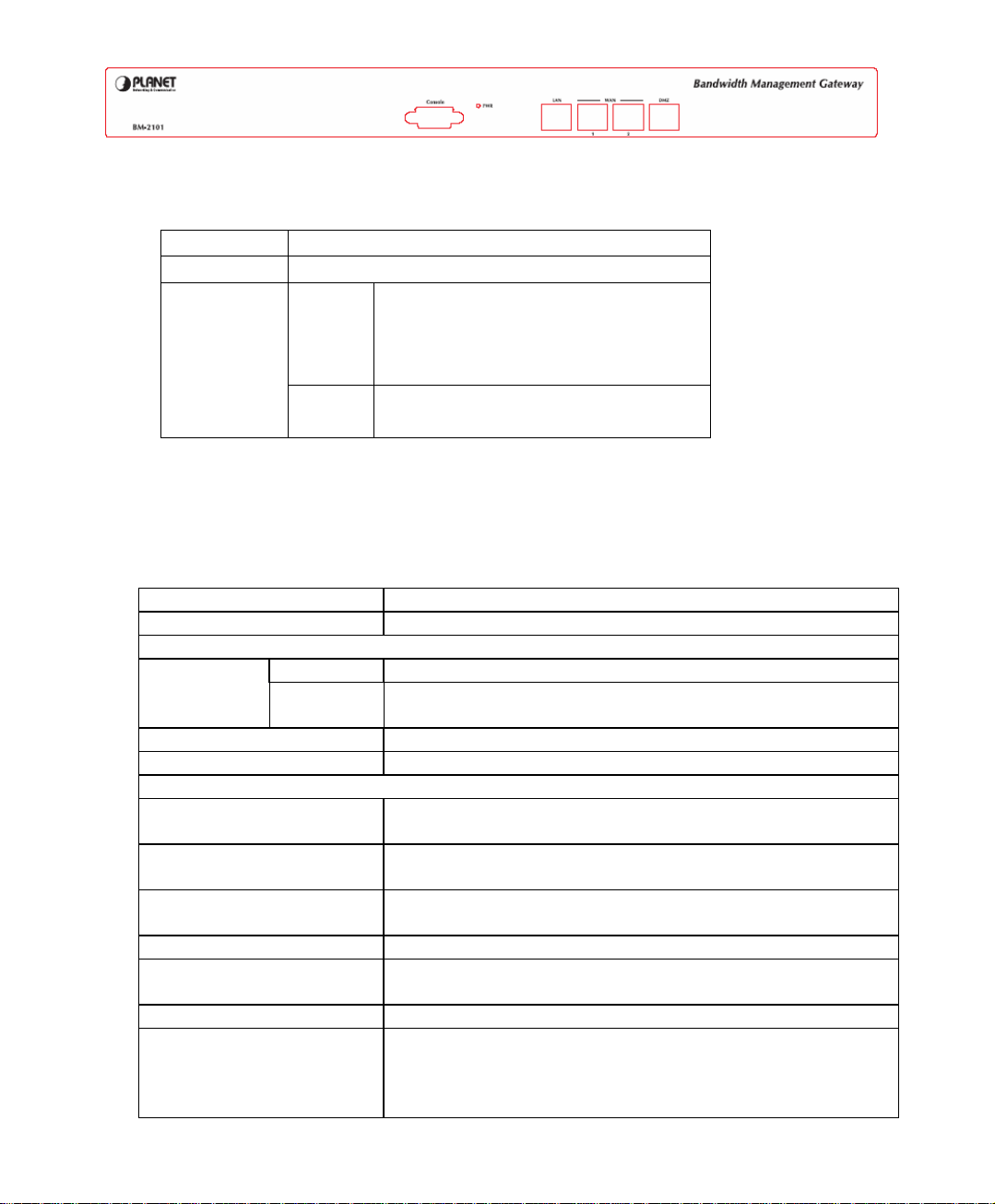
LED definition
LED Description
PWR Power is supplied to this device.
WAN1,
WAN2,
LAN,
DMZ
Green Steady on indicates the port is
connected to other network device.
Blink to indicates there is traffic on
the port
Orange Steady on indicates the port is
connected at 100Mbps speed
1.3 SPECIFICATION
Product Bandwidth Management Gateway
Model BM-2101
Hardware
WAN 2 x 10/100Base-TX Connections
LAN
DMZ
Console 1 x RS-232 (DB-9)
H/W Watch-Dog Auto reboot when detecting system fail
Software
Maximum Controlled
Bandwidth
Maximum Controlled
concurrent session
Management Web (English, Traditional Chinese, Simplified
Operation Mode DMZ_NAT, DMZ_Transparent, NAT
WAN connection type in
NAT mode
Traffic Classification IP, IP subnet, and TCP/UDP port
Bandwidth Allocation Policy rules with Inbound/Outbound traffic
1 x 10/100Base-TX, Auto-MDI/MDI-X
1 x 10/100Base-TX, Auto-MDI/MDI-X
100Mbps
241,000
Chinese)
PPPoE, DHCP, and Fixed IP
management
Guaranteed and maximum bandwidth
Scheduled in unit of 30 minutes
7
Page 9

3 Priorities
Quota per Session and Quota per Day
Log Traffic Log, Event Log, Connection Log, Log backup
by mail or syslog server
Statistics WAN port statistics and policy statistics with graph
display
Firewall Security Policy-based access control
Stateful Packet Inspection (SPI)
Scheduled in unit of 30 minutes
Hacker Alert and
Anomaly Flow Detection
Detect SYN Attack, Detect ICMP Flood, Detect UDP
Flood, Detect Ping of Death Attack, Detect Tear Drop
Attack, Detect IP Spoofing Attack, Filter IP Route
Option, Detect Port Scan Attack, Detect Land Attack,
Virus-Infected Blocking, E-Mail Alert Notification,
NetBIOS Notification
Alarm Event alarm for hacker attack
The alarm message can sent to administrator by e-mail
Other Functions Firmware Upgradeable through Web
NTP support
Configuration Backup and Restore through Web
Dynamic DNS support
Multiple NAT and multiple DMZ (mapped IP) support
Multiple server load balancing
8
Page 10

Chapter 2
AAddmmiinniissttrraattiioon
Generally speaking, the system administration refers to the privileges of log in/out,
monitor and control the BM-2101 appliance with some relevant settings. In this Chapter,
the system administration will be defined as the management of the MIS engineer ,
Permitted IPs , System Log-Out, and Software Update.
Chief administrator configures and manages the BM-2101 appliance. The
administrator can add, delete or modify system settings and monitor system status while
sub-administrator (title named by first MIS engineer) is read-only.
n
9
Page 11

Administrator
Administrator
The title of chief administrator and sub administrator. Administrator is the default
name and cannot be removed. But other sub administrator can be modified or
removed.
The default administrator Account: admin ; Password: admin
The default chief administrator can add or modify the other admin to be the sub admin or chief
admin , otherwise the other chief admin can modify its privilege to be the sub admin but can not be
deleted . The BM-2101 appliance still force to reserve a chief admin .
Privilege
Chief administrator has the Write/Read privilege. Administrator is allowed to
modify the configurations, monitor the system status, and add or remove the other
administrator .
Sub administrator only has Read privilege. He is allowed to view and monitor data,
but cannot modify the configurations.
Password/New Password/Confirm Password :
Can add or modify the password of chief / sub administrator .
10
Page 12
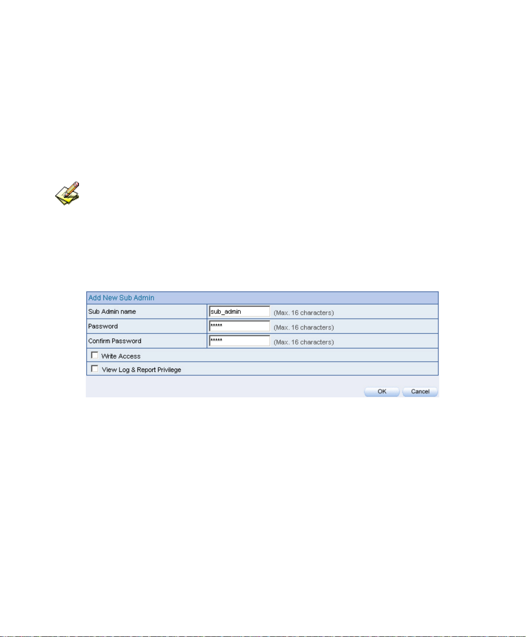
2.1 Admin
Step1. Click Admin Æ New Sub-Admin .
Step2. In Add New Sub Admin , add the settings :
Sub Admin name: sub_admin.
Password: 12345.
Confirm Password: 12345.
If select Write Access and View Log & Privilege, the new sub-admin becomes chief admin.
Step3. Click OK for the user to log in, or click Cancel to cancel adding new sub
admin.
Add new sub admin
11
Page 13
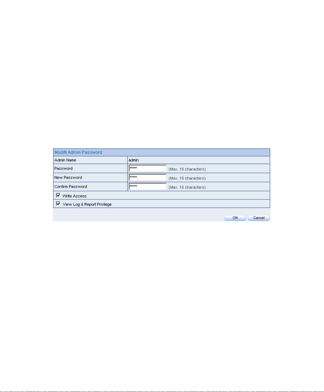
Step1. In Admin, select the admin to change , correspond to the ConfigureÆ
Modify.
Step2. In Modify Admin Password , enter the following information:
Password: admin.
New Password: 52364.
Confirm Password: 52364.
Step3. Click OK to change the password, or click Cancel to cancel the
modification
Modify admin password
12
Page 14
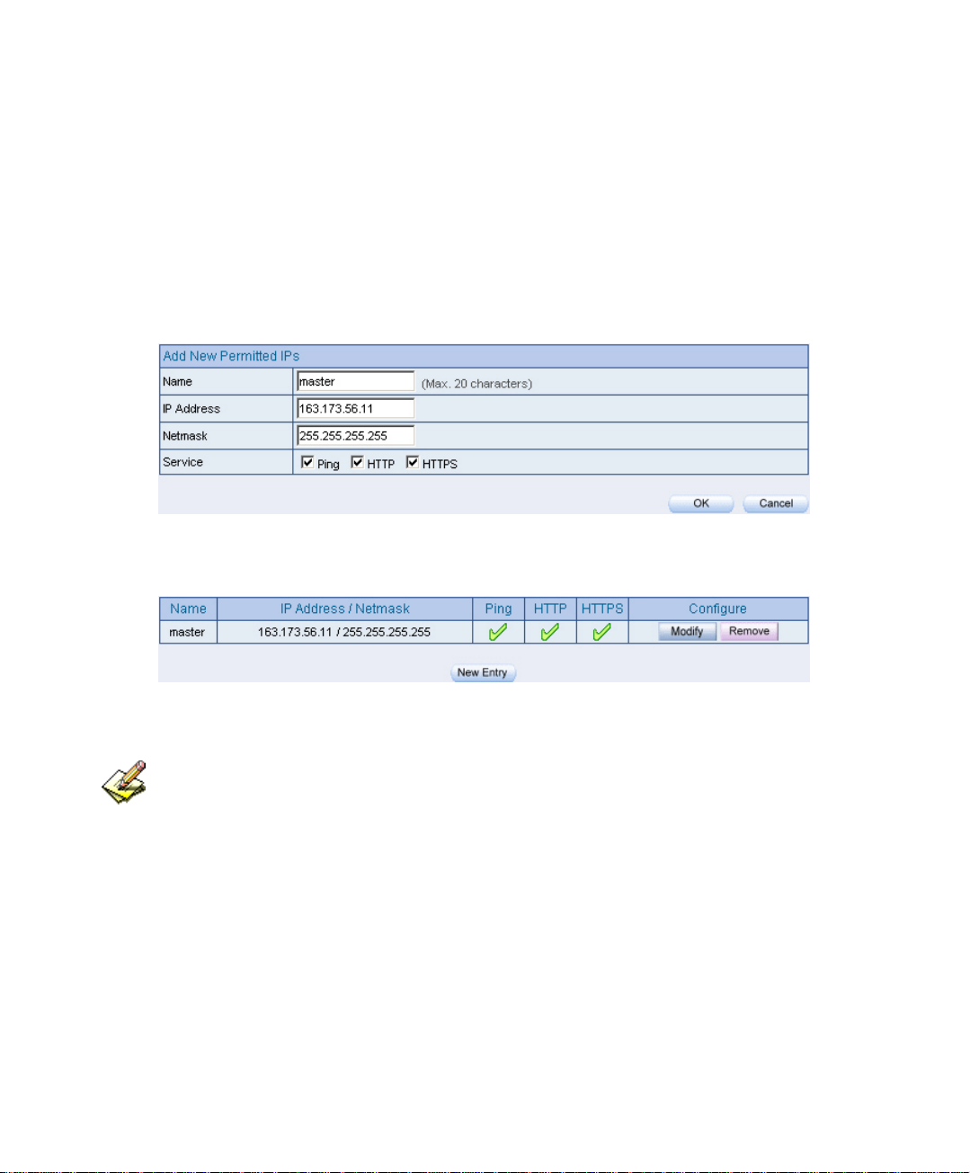
2.2 Permitted IPs
Step1. In Administration Æ Permitted IPs ÆNew Entry , add the settings :
Name : Enter master
IP Address : Enter 163.173.56.11
Netmask : Enter 255.255.255.255
Service : Check Ping, HTTP and HTTPS
Click OK
Compelte adding Permitted IPs
Add new Permitted IPs
Complete add new Permitted IPs
To activate Permitted IPs, click Interface Æ LAN, WAN, and DMZ to uncheck Ping ,HTTP, and
HTTPS. However, Permitted IPs must be set before the cancellation of HTTP and HTTPS, or MIS
engineer can not enter BM-2101’s Web UI via the appointed interface.
13
Page 15
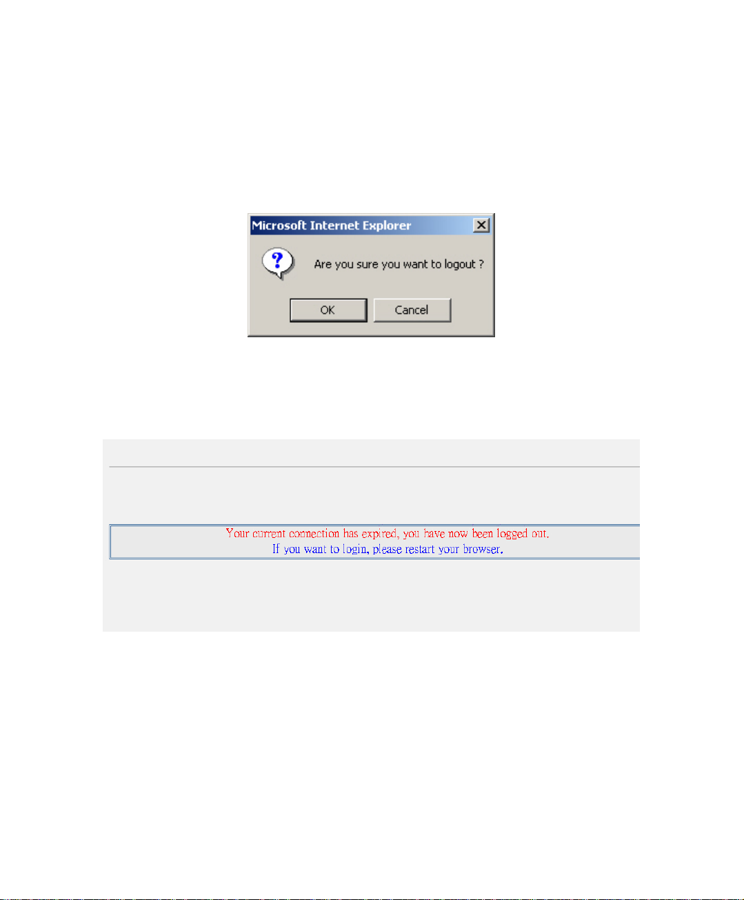
2.3 System Log Out
. Step1 Click the Logged icon at the upper right of the WebUI. The MIS engineer
can log out the system anytime, to prevent the other person change the
setting through other PC.
Confirm to log out
Step2. Click OK . It shows the logout message.
Log out message
14
Page 16
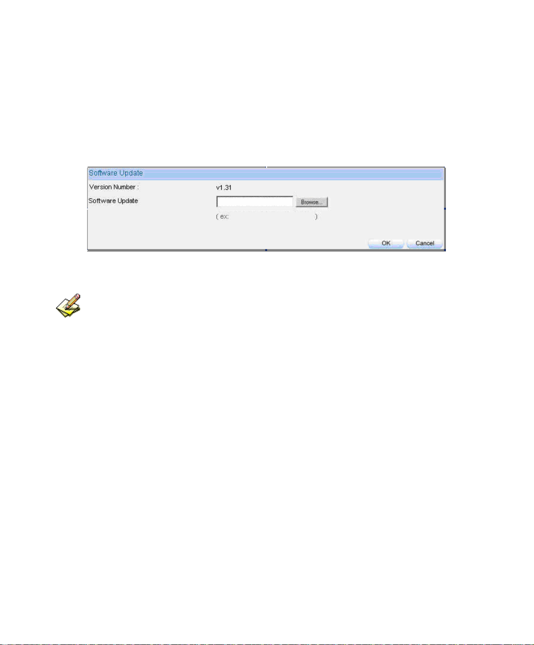
2.4 Software Update
Step1. In SystemÆAdministrationÆSoftware Update:
In Version Number, to know the version number, then connect to
network and download the latest version in the BM-2101 appliance.
Click Browse Æ Choose File , select the latest update file and open
it.
Click OK to run automatic software update.
Firmware update
It takes 3 minutes to run software update then the system will restart. Please do not turn off the
system or quit the web page during the update process, or it will cause an unpredictable error (It is
recommended to update through LAN).
15
Page 17

Chapter 3
CCoonnffiigguurre
The configuration here is about the basic operating settings of the BM-2101 appliance.
In this Chaper, it will be defined as Setting, Date/Time, Multiple Subnet, Route Table,
DHCP, Dynamic DNS, Host Table, SNMP, and Language.
e
16
Page 18

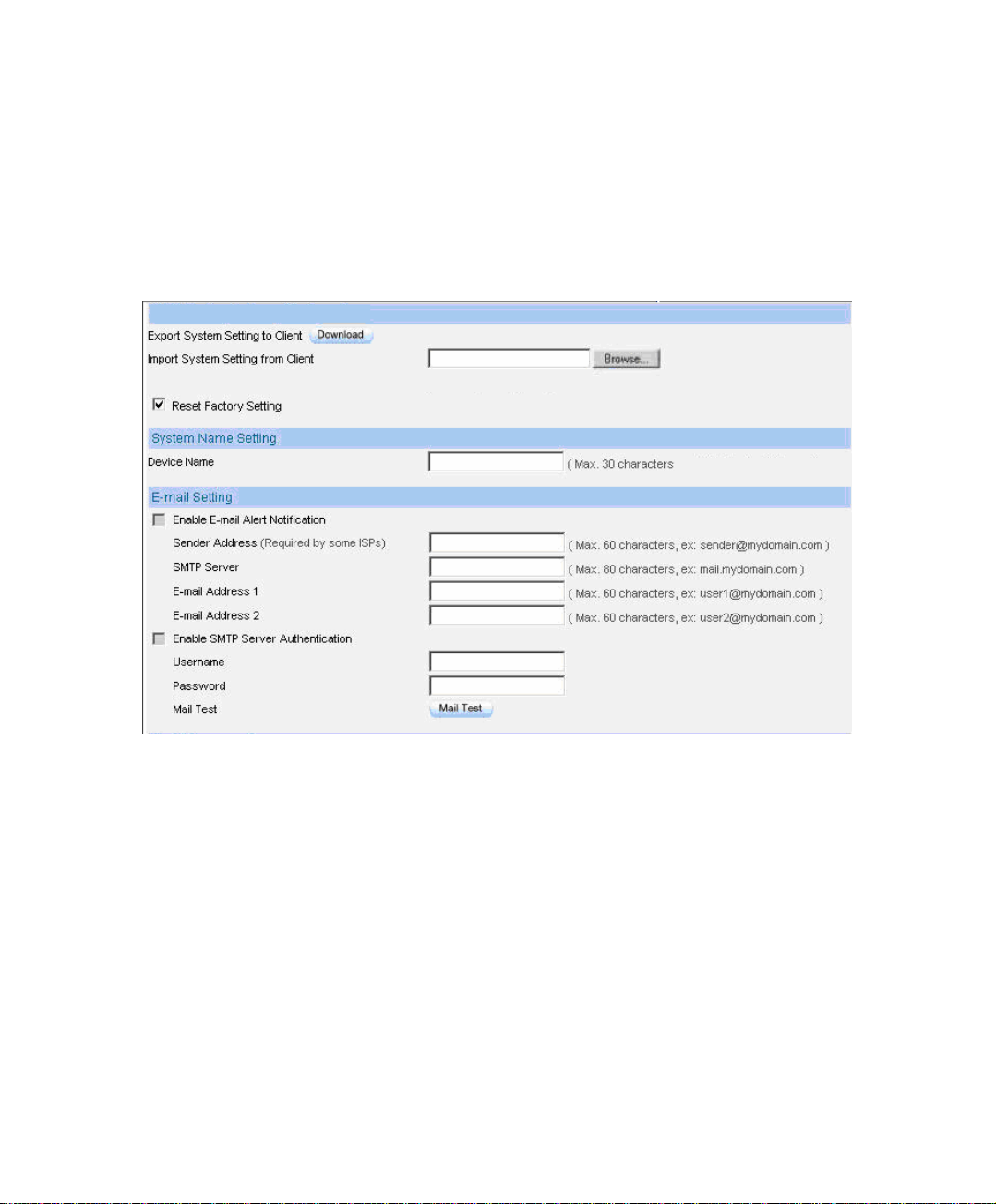
Setting
Bandwidth Management Gateway Configuration
The MIS engineer can export or import system setting files and reset factory
setting
System Name Setting
The administerator can set the device name.
E-mail Setting
Enabling this function and the BM-2101 appliance will automatically send instant
e-mail alert notification to the MIS engineer when the system be attacked or some
urgent events occured .
Web Management
The MIS engineeristerator can remote the BM-2101 appliance anywhere via Web
UI. In addition, the MIS engineer can change the used port number in BM-2101’s
remote management .
Set up the idle timeout as the MIS engineer log into the BM-2101 appliance. The
BM-2101 appliance will forced to logout the Web UI as the MIS engineer did not
process any system monitoring or management.
After changing HTTP or HTTPS port number, if the MIS engineer want to log in to Web UI from
the WAN , he must change the web browser’s port when log in to Web UI (For example ,
http://61.62.108.172:8080 and https://61.62.108.172:1025)
MTU Setting
The MIS engineer can modify the length of the sent and received packets anytime.
The default value is 1500 Bytes.
17
Page 19

Dynamic Routing (RIPv2)
By enable LAN, WAN or DMZ Port to send and receive RIPv2 packets, the BM-
2101 appliance can communicate with internal or external routers and dynamically
update the route table. ( The MIS engineer can set up routing information update
timer and routing information timeout when it stopp to receive the RIPv2 packets
and the router will automatically cancel the dynamic routing table according to the
setting.)
Administration Packet Logging
After enabled this function, the system will record the source or destination packet
information of BM-2101 in Monitor Æ Log Æ Traffic for the MIS engineer to
query.
Date / Time
Synchronize System Clock
Synchronize the BM-2101 appliance time to the MIS engineer’s PC or the external
time server.
GMT
International Standard Time (Greenwich Mean Time)
Multiple Subnet
WAN Interface IP
The WAN interface IP which a multiple subnet corresponds to.
Forwarding Mode
To indicate the multiple subnet use NAT or Routing mode.
Interface
To indicate the multiple subnet interface is LAN or DMZ interface.
18
Page 20

Alias IP of Interface/Netmask
The multiple subnet segment range.
NAT Mode
Allow the internal network to set up multiple subnet addresses and connect to
network via different WAN IP addresses. For example , the company applies
several real IP addresses 168.85.88.0/24 for its lease line, and the company is
divided into R&D, Customerr Service, Sales, Procurement, Accounting
Department. For easy management, assignate different IP segment for each
department. The settings are as the following:
R&D Dep. 192.168.1.1/24(Internal) ÅÆ 168.85.88.253(External)
Custermor Service Dep. 192.168.2.1/24(Internal) ÅÆ 168.85.88.252(External)
Sales Dep. 192.168.3.1/24(Internal) ÅÆ 168.85.88.251(External)
Procurement Dep. 192.168.4.1/24(Internal) ÅÆ 168.85.88.250(External)
Accounting Dep. 192.168.5.1/24(Internal) ÅÆ 168.85.88.249(External)
R&D Dep. has already been set up in Interface configurations, so set up the
reserveing four departments by adding 4 new Multiple Subnets . After completing
the settings, every department can connect to network via its own WAN IP address.
The settings of each department are as the following:
Customer
Service
IP Address 192.168.2.2~254 192.168.3.2~254 192.168.4.2~254 192.168.5.2~254
Netmask 255.255.255.0 255.255.255.0 255.255.255.0 255.255.255.0
Default
Gateway
Routing Mode
It is almost the same as NAT mode but does not have to correspond to the real
WAN IP address, which let internal PC to access the network by its own IP.
(External user can use the IP to connect to the network)
192.168.2.1 192.168.3.1 192.168.4.1 192.168.5.1
Sales Procurement Accounting
19
Page 21

DHCP
Subnet
The domain belongs to internet network.
Netmask
The domain name netmask belongs to the internet network.
Gateway
Internal network default gateway.
Broadcast
LAN broadcast address.
Dynamic DNS
Domain Name
The domain name that the MIS engineer applied from the DDNS provider.
WAN IP
The real IP which the domain name correspond to.
Host Table
Host Name
Customized by the MIS engineer. The internal user can access the resources
provided by a corresponded host.
Virtual IP Address
The mapped virtual IP Address correspond to the host name. It must be the LAN or
DMZ IP address.
20
Page 22
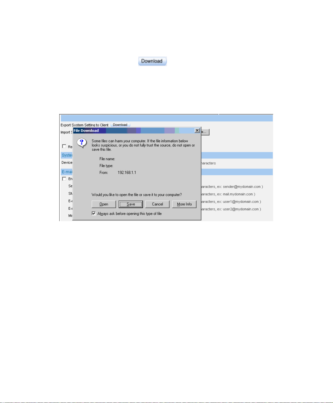
3.1 Setting
Step1. In SystemÆConfigureÆSetting ÆBandwidth Management Gateway
Configuration , click
Step2 In File Download window , click Save . Then, choose the destination
.
near Export System Setting to Client.
location to save the exported file. Finally, click Save for BM-2101 to copy
the configuration file to the oppointed storage location.
Choose the location to save files
21
Page 23
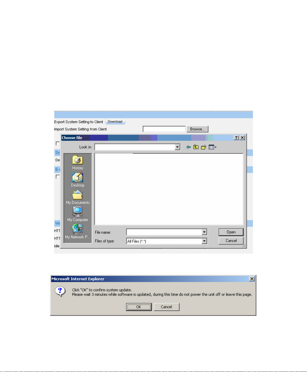
Step1. In Setting window, click Browse near Import System Setting from
Client .
Step2. In Choose File window, select the previously saved settings and click
Open .
Step3. Click Open, and a confirmation dialogue box pop out.
Step4. Click the OK to import the configuration file.
Import the file
To confirm to import the file
22
Page 24
Step1. In Setting ÆBandwidth Management Gateway Configuration , select
Restore Factory Setting.
Step2. Click OK to restore the default settings
Restore to factory setting
23
Page 25
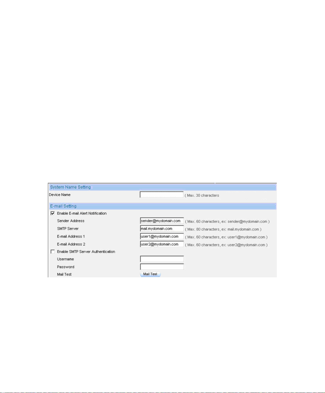
Step1. Device Name:Enter the BM-2101 name.
Step2. In E-Mail SettingÆEnable Email Alert Notification .
Step3. Sender Address : Enter the sender’s email address. (Required by some
ISP).
Step4. SMTP Server : Enter the IP address of the SMTP server.
Step5. E-mail Address 1 : Enter the first e-mail address to receive the notification.
Step6. E-mail Address 2 : Enter the second e-mail address to receive the
notification.
. Step7 Click OK to enable this f unction.
Enable e-mail alert notification
24
Page 26

Click Mail Test to test if e-mail address 1 and e-mail address 2 can receive the notification
or not.
If the MIS engineer want to send the mails via the authentication, then he must Enable SMTP
Server Authentication.
25
Page 27

Step1. To restart the BM-2101 appliance, Click Reboot near Reboot Bandwidth
Management Gateway Appliance.
Step2. It shows the confirm dialogue of Are you sure to reboot ?
Step3. Click OK to restart, or click Cancel to terminate the action.
Start to reboot
26
Page 28
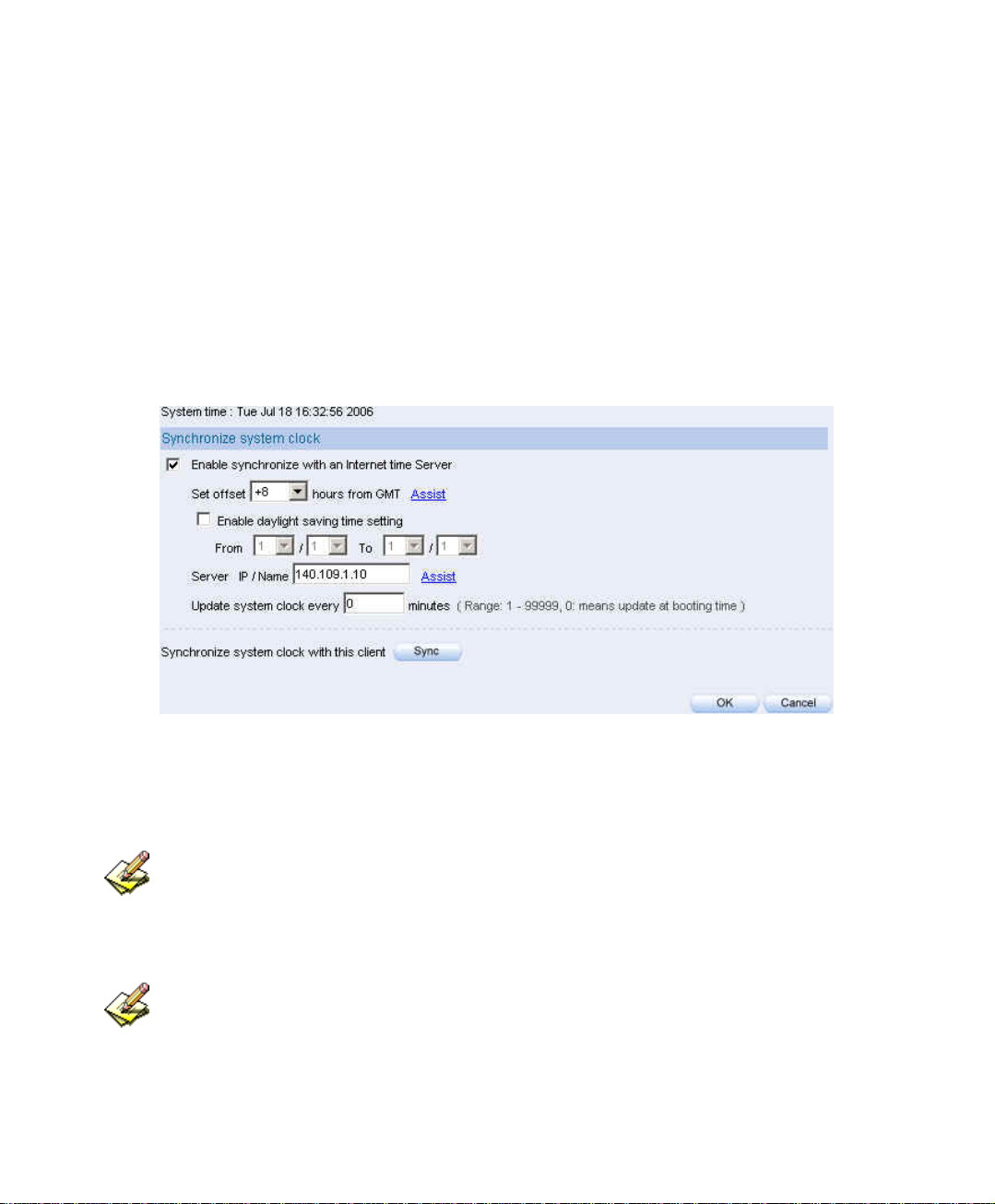
3.2 Date / Time
Step1. Select Enable synchronize with an Internet time Server.
Step2. Set offset hours from GMT , select the correct option.
Step3. Enter the time server’s IP address in Server IP / Name.
Step4. Enter the update time.
Set system clock
Click Sync near Synchronize system clock with this client, to synchronize the BM-2101 time to
the MIS engineer’s PC.
Click Assist near Set Offset From GMT or Server IP / Name to consult the setting
value.
27
Page 29

3.3 Multiple Subnet
Internal user use the IP address to link the internet via the multiple subnet NAT or
Routing mode.
Preparations
Connect the BM-2101 appliance WAN 1(10.10.10.1)to the ISP’s Router (10.10.10.2).
The segment is 162.172.50.0/24 (Distributed by the ISP).
Connect the BM-2101’s WAN 2(211.22.22.22)to ATUR to link to the network.
28
Page 30
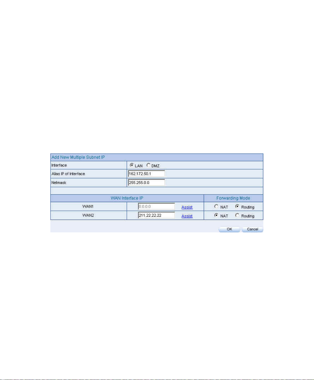
Step1. Click Configure Æ Multiple Subnet :
Click New Entry .
Interface : select LAN
Alias IP of Interface : enter 162.172.50.1
Netmask : enter 255.255.255.0
WAN 1: 10.10.10.1 , Forwarding Mode : select routing
WAN 2: 211.22.22.22 , Forwarding Mode : select NAT
Click OK .
Complete to add new multiple subnet IP.
Add new multiple subnet IP
29
Page 31

Can enter the interface IP of WAN 1 & WAN 2 by Assist.
After completed the settings, there are two LAN segment 192.168.1.0/24 (the default LAN segment)
and 162.172.50.0/24. Therefore, if the LAN IP is::
192.168.1.xx –Use the NAT Mode to connect to the network (As regulated in Policy, one can only
connect to network via WAN2. If use Routing mode via WAN 1, an virtual IP can’t be usd to
connect to network).
162.172.50.xx—WAN 1: Routing mode (MIS engineer IP 162.172.50.xx can be seen by the
internet server ) ; WAN2: NAT mode (The IP seen by the internet server is WAN2’s IP)
30
Page 32

Multiple Subnet deployment
BM-2101 Interface:
WAN1 IP:10.10.10.1
WAN2 IP:211.22.22.22
LAN Port IP:192.168.1.1
LAN Port Multiple Subnet:162.172.50.1
31
Page 33

3.4 Route Table
Internet Make the Router which deploy in two different segment can link to the internet
via the BM-2101 appliance.
Preparations
Company A
Connect WAN 1(61.11.11.11)to ATUR and link to network.
Connect WAN 2(211.22.22.22)to ATUR and link to network.
LAN segment is192.168.1.1/24.
LAN Router1(10.10.10.1, supporting RIPv2), the LAN segment is
192.168.10.1/24.
Company B
Router2(10.10.10.2, supporting RIPv2), the LAN segment is
192.168.20.1/24.
Company A’s Router1(10.10.10.1)is connected to B company’s Router2
(10.10.10.2)by lease line directly.
32
Page 34

Step1. In Configure Æ Route Table :
Destination IP : Enter 192.168.10.1
Netmask : Enter 255.255.255.0
Gateway : Enter 192.168.1.252
Interface : Select LAN.
Click OK
Add new static route-1
Step2. In Configure Æ Route Table
Destination IP: Enter 192.168.20.1
Netmask: Enter 255.255.255.0
Gateway : Enter 192.168.1.252
Interface : Select LAN .
Click OK
Add new static route-2
33
Page 35

Step3. In Configure Æ Route Table:
Destination IP : Enter 10.10.10.0
Netmask : Enter 255.255.255.0
Gateway : Enter 192.168.1.252
Interface : Select LAN .
Click OK
Add new static route -3
34
Page 36

. Step4 As completed all. The BM-2101 appliance can translate the virtual IP to
real IP. Therefore, the LAN subnet PC 192.168.10.1/24, 192.168.20.1/24
and 192.168.1.1/24 can communicate to each other via the BM-2101
appliance.
Route table environment
35
Page 37

3.5 DHCP
Step1. In Configure Æ DHCP , to select and set the following setting:
Domain Name: Enter the domain name in private LAN .
DNS Server 1: Enter the IP address distributed to DNS server 1.
DNS Server 2: Enter the IP address distributed to DNS server 2.
WINS Server 1: Enter the IP address distributed to WIN server 1.
WINS Server 2: Enter the IP Address distributed to WIN server 2.
LAN Interface:
Client IP range 1: Enter the first starting and ending IP addresss,
the default value is 192.168.1.2 to 192.168.1.254. (it must be at the
same domain).
Client IP range 2: Enter the second starting and ending IP addresss
(it must be at the same domain as Client Range 1).
DMZ Interface:Set as the LAN interface address. (Except to enable
DMZ Interface , click InterfaceÆDMZ .)
Leased Time:The lease time of the dynamic IP, and the default value
is 24 hours.
Click OK .
Complete DHCP settings.
36
Page 38

DHCP setting
When the LAN network adaptor set to Automatically Get DNS. The DNS Server will auto lock
the LAN interface IP . ( Note : When enabled the Authentication , the first DNS server must
correspond to the LAN interface IP).
37
Page 39

3.6 DDNS
Step1 In Configure Æ DDNS .
.
Click New Entry .
Service Provider : Select from the drop-down menu.
Select Automatically and select a WAN interface to correspond from
the menu.
User Name and Password : Enter the applied name and password.
Domain Name : Enter the applied domain name.
Click OK .
Complete DDNS setting.
DDNS setting
Complete the DDNS setting
38
Page 40

Icon
Connotation Connection
Succeed
Wrong
Password
Connecting Errors
If the MIS engineer have not apply the DDNS account, then he can choose the proper DDNS
supplier, click Sign up, and then it will display the registeration web page.
If the MIS engineer do not select Automatically correspond to the WAN interface
Address, then they can enter the specific IP at WAN IP. It can let DDNS correspond to the static IP.
39
Page 41

3.7 Host Table
Step1. In Connfigure Æ Host Table:
Host Name enter the customerized domain name
Virtual IP Address enter the host name that correspond to the virtual
IP address.
Click OK .
Complete Host Table setting
Host table setting
Use the Host Table of the BM-2101 appliance, the first DNS Server in Client PC must correspond
to the LAN or DMZ Port IP; that is the default gateway of the computer.
40
Page 42
3.8 SNMP
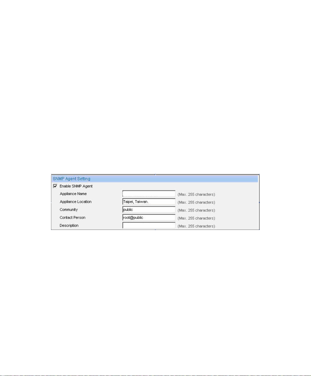
Step1. In Configure Æ SNMP Æ Enable SNMP Agent and enter the following
setting:
Appliance Name : Can customize the name. Default setting is
Bandwidth Management Gateway.
Appliance Location : Can customize the settings. Default setting is
Taipei, Taiwan.
Community : Can customize the settings. Default setting is public.
Contact Person : Can customize the settings. Default setting is
root@public.
Description : Can customize the settings. Default setting is Multi
Home Appliance.
Click OK .
Complete the SNMP Agent settings. The MIS engineer can monitor
BM-2101’S operating status by the SNMP Agent message recipient
installed in administrator’s PC.
SNMP Agent setting
41
Page 43
Configure
SNMP
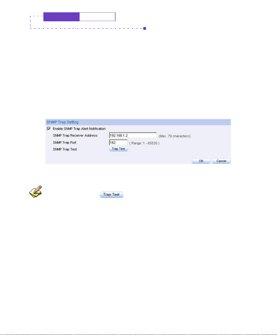
Step1. In Configure Æ SNMP , select Enable SNMP Trap Alert Notification
and enter the following setting:
SNMP Trap Recipient Address, enter SNMP trap recipient IP.
SNMP Trap Port : Enter the port number. (Default value: 162).
Click OK .
Complete the SNMP Trap setting. The MIS engineer can use the
SNMP Trap software and receive the alarm notification from the BM2101 appliance.(it will send the notification about connection /
disconnection and the attacks information to the SNMP Trap recipient
address
.
SNMP Trap setting
The MIS engineer can click to test if SNMP Trap can wrok normally.
42
Page 44

3.9 Language
Step1. In Configure Æ Language to select the language, Click OK.
Select language
43
Page 45

Chapter 4
IInntteerrffaacce
The so called interface included the LAN and WAN of the BM-2101 appliance.
In Interface, the MIS engineer can set the IP address, netmask, gateway address,
and define the WAN and LAN IP address, all depends on the chosen ISP connection.
e
44
Page 46

Interface
LAN
Can set up the LAN network .
Ping
Can test the IP via Ethernet interface.
HTTP
From the Ethernet interface to the BM-2101 WebUI through HTTP.
HTTPS
From the Ethernet interface to the BM-2101 Web UI through HTTPS.
WAN
Can set the external connection.
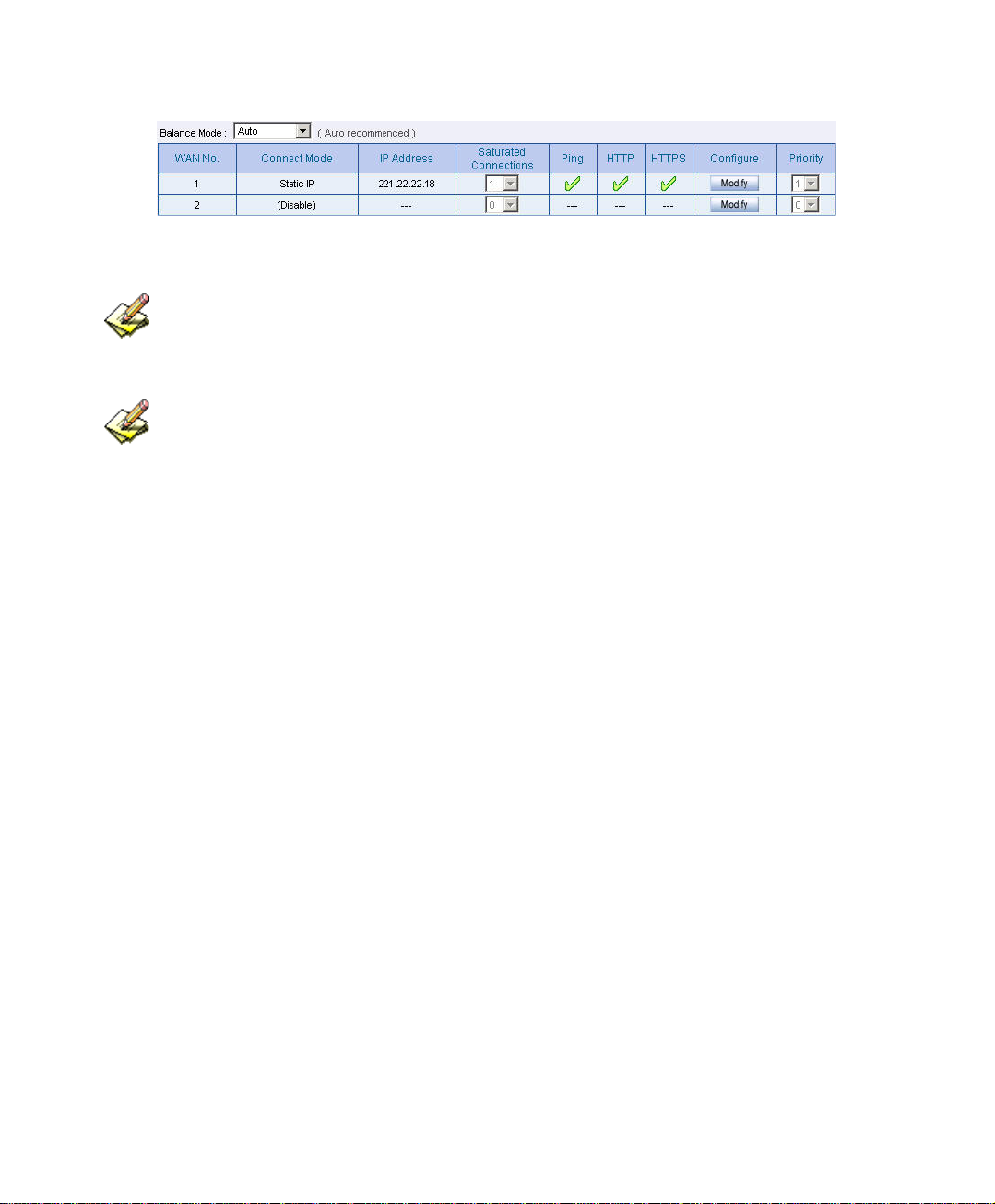
Balance Mode
Auto:Can auto adjust the usage of WAN depends on the downstream and
upstream status . (Suitable for the user who use different downstream bandwidth)
Round-Robin:Forced to use the 1:1 cycling distribution of network download
connection (it is appropriate to the users who use the same download bandwidth.)
By Traffic:Allocate the download bandwith by accumulated network flow.
By Session :Adjust the WAN connection depends on the saturated connections.
By Packet:Allocate the download bandwidth by accumulated packets .
45
Page 47

Connect Mode
The WAN network connection mode can be divided into :
PPPoE (ADSL user )
Dynamic IP Address (cable modem user)
Static IP address (static connection or ADSL static line users )
Saturated Connections
Can set the WAN connections depend on the traffic , connections and packets.
Priority
Set the WAN interface priority by balance mode choice.
Service
To test if the WAN can work or not. The testing includes two parts:
ICMP:Ping the IP to see if the connection can work.
DNS:Use the domain name to see if the connection can work.
Downstream Bandwidth and Upstream Bandwidth
Can set the proper bandwdith of the WAN interface.
The Idle Time
As the WAN interface set to be the PPPoE (ADSL users ) settings, the MIS
engineer can set the idle time when the WAN port is not in use. (Its unit is minute)
46
Page 48

DMZ
Can set the DMZ in the BM-2101 appliance.
The DMZ includes two modes:
NAT:The DMZ is an isolated virtual domain. (but it can not be at the same
segment as LAN).
TRANSPARENT:The DMZ and WAN interface are both in the same
domain .
47
Page 49

We set 4 environments.
No. Range The Application Environment
Example 1
Example 2
Example 3
Example 4
LAN
WAN
DMZ
DMZ
Modify the LAN interface address.
Set the WAN interface address.
Set the DMZ interface address(NAT mode).
Set the DMZ interface address(DMZ_Transparent
mode).
48
Page 50

4.1 LAN
Modify the LAN Interface Address
Step1. In Interface Æ LAN to enter the following settings:
Enter the new LAN IP Address and Netmask .
Select Ping, HTTP and HTTPS.
Click OK
LAN Interface IP setting
The default LAN interface address is 192.168.1.1. After the MIS engineer has modified the LAN IP
address, he has to set the PC to obtain the latest IP, then use the modified LAN interface IP address to log
in Web UI. (When the PC set to obtain the IP by DHCP)
Before set the Permitted IP,never uncheck HTTP and HTTPS or the MIS engineer will not able
to log in the BM-2101 Web UI via LAN.
49
Page 51

4.2 WAN
Set the WAN Interface Address
Step1. Interface Æ WAN, click Modify of WAN 1 .
WAN 2 Interface’s settings are almost the same as WAN 1 setting. The difference is that WAN 2
has the additional Disable function. The MIS engineer can use this function to disable WAN Interface
2.
Disable the WAN Interface
50
Page 52

Step2. The way to test the connection (ICMP and DNS):
ICMP: enter the persistant ping IP.( Or click Assist ).
DNS:enter the DNS server IP address and domain name (Or click
Assist).
Sets the interval seconds during the packets transferring ( per seconds).
ICMP test
DNStest
Both of the two connection test is the standard to see if the WAN can work
properly. The testing such as the IP address, IP address for DNS server and the domain
name all must be working forever long , or it will make the BM-2101 appliance error.
51
Page 53

Step3. Choose the network connection .
PPPoE (ADSL User)
1. Select PPPoE (ADSL User)
2. Enter User Name as an account.
3. Password as the applied password.
4. Select Dynamic or Fixed in IP Address provided by ISP. It
depends on the user’s network status , click Fixed option, please
enter the IP address, Netmask and Default Gateway.
5. Enter Max. Downstream Bandwidth and Max. Upstream
Bandwidth (※It depnds on the network bandwidth which the user
applied .)
6. Select Ping , HTTP , and HTTPS
7. Click OK .
52
Page 54

Select PPPoE
Complete PPPoE setting
If use the PPPoE ,the MIS engineer can set the WAN interface auto connect when it disconnect (it
is recommended enable this function ) or set the WAN interface disconect as idle.(Not
Recommended ).
53
Page 55

Dynamic IP Address ( cable modem user )
1. Click Dynamic IP Address .
2. Click IP AddressÆRenew , then get the Dynamic IP .
3. If the ISP require to enter the MAC address , Click MAC
AddressÆClone MAC, then get the MAC address .
4. User Name:Require by the ISP to enter the provided user name .
5. Domain Name:Require by the ISP to enter the provided domain
name .
6. Username and Password : The IP machenism of
DHCP+authentication.(According to the ISP in Mainland Cnina )
7. Enter DownstreamBandwidth and Upstream Bandwitdth(※
According to the bandwidth which applied by the user)
8. Select Ping , HTTP and HTTPS .
9. Click OK .
Select Dynamic IP address
54
Page 56

Complete to set the Dynamic IP address
55
Page 57

Static IP address(For Static or ADSL user)
1. Select Static IP Address .
2. Enter IP Address , Netmask and Default Gateway .
3. Enter DNS Server 1 or DNS Server 2 .
4. Enter Max. Downstream Bandwidth and Max. Upstream (※
According to the bandwidth applied by the user)
5. Select Ping , HTTP and HTTPS .
6. Click OK
Set the Static IP address
56
Page 58
Complete to set the Static IP address
In WAN 2 Interface, the MIS engineer has no need to set the DNS server as setting the Static IP
address.
When selecting Ping , HTTP and HTTPS in WAN interface , the user can ping the BM-2101
appliance and its WebUI . This action may cause the network security problem. It’s recommended do not
selet the Ping, HTTP, and HTTPS after confirming all the setting is completed . If the MIS engineer want
to log in to the WebUI through WAN, he can use System Æ Administration Æ Permitted IPs .
57
Page 59

4.3 DMZ
Set up DMZ Interface (NAT Mode)
Step1. In Interface Æ DMZ .
Step2. In DMZ Interface, select NAT mode.
In DMZ Interface , select NAT from the drop-down menu.
Enter the value in IP Address and Netmask .
Step3. Select Ping , HTTP and HTTPS .
Step4. Click OK
Select the NAT mode
58
Page 60
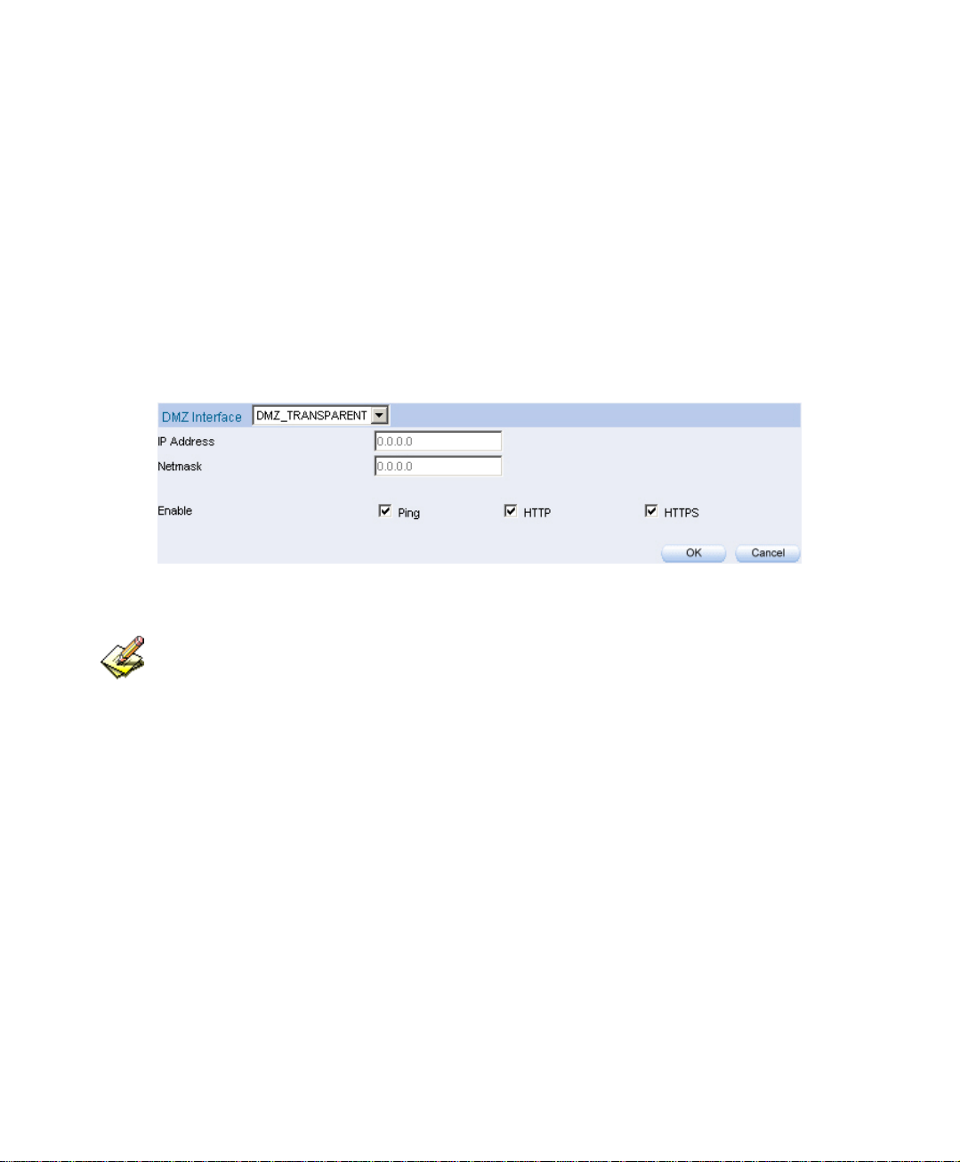
Set up DMZ Interface (Transparent Mode)
Step1. In Interface Æ DMZ .
Step2. In DMZ Interface, select Transparent Mode.
In DMZ Interface, select DMZ_ Transparent Mode from the drop-
down menu .
Step3. Select Ping , HTTP , and HTTPS .
Step4. Click OK
Select DMZ transparent mode
The MIS engineer has to set the static IP address in WAN interface and select the
DMZ_TRANSPARENT mode in DMZ interface.
59
Page 61

Chapter 5
AAddddrreesss
In this chapter , it includes the definition of the chief MIS engineer , LAN , LAN
group , WAN , WAN group , DMZ and DMZ group.
The IP address recorded in Address is probably a host IP address , or represents
many IP address in the Domain .The MIS engineer can set an easy to identicy name to
represent the IP address . Basically , the IP address can divided into three types:
internal IP address , WAN IP address and DMZ IP address. The MIS can apply the
different IP address packets filtering rules to the same policy , he can set these IP
address in LAN group , WAN group or DMZ group.
After finished the Address setting, the MIS engineer can apply the address setting to the
policy( source address or destination address) . In other words , the Address setting must be set before the
s
policy setting , so that it can shows the correct IP Address in Address setting.
60
Page 62

Address
Name
The MIS engineer can set the easy to identify name of IP address .
IP
It can be a host IP address or one of the domain IP address. It included threee
different types : internal IP address , external IP address and DMZ IP address .
Netmask
Correspond to the single static IP address , the setting must be : 255.255.255.255.
Correspond to many IP address in a specific domain . For example, IP Address
192.168.100.1 in C Class segment , the setting must be 255.255.255.0 .
MAC Address
Mapped the MAC address to its IP address . It can prevent the user to modify the
IP address and access the unauthorized network service through the policy .
Get IP address from DHCP Server
When enable this function,LAN or DMZ will get the PC ‘s IP address via the
DHCP server in the BM-2101 appliance, and the PC’s IP address will correspond
to the MAC address.
61
Page 63

We set two environments.
No. Range The Application Environment
Example 1
LAN
When use the DHCP, to distribute the static IPaddress to
the specific user and limit the user can only access the
FTP resources through policy .
Example 2
LAN Group
and WAN
To set the policy which allow part of users connect to the
remote static IPaddress.
62
Page 64

5.1 Example
When use the DHCP, to distribute the static IPaddress to the specific user and limit the
user can only access the FTP resources through policy.
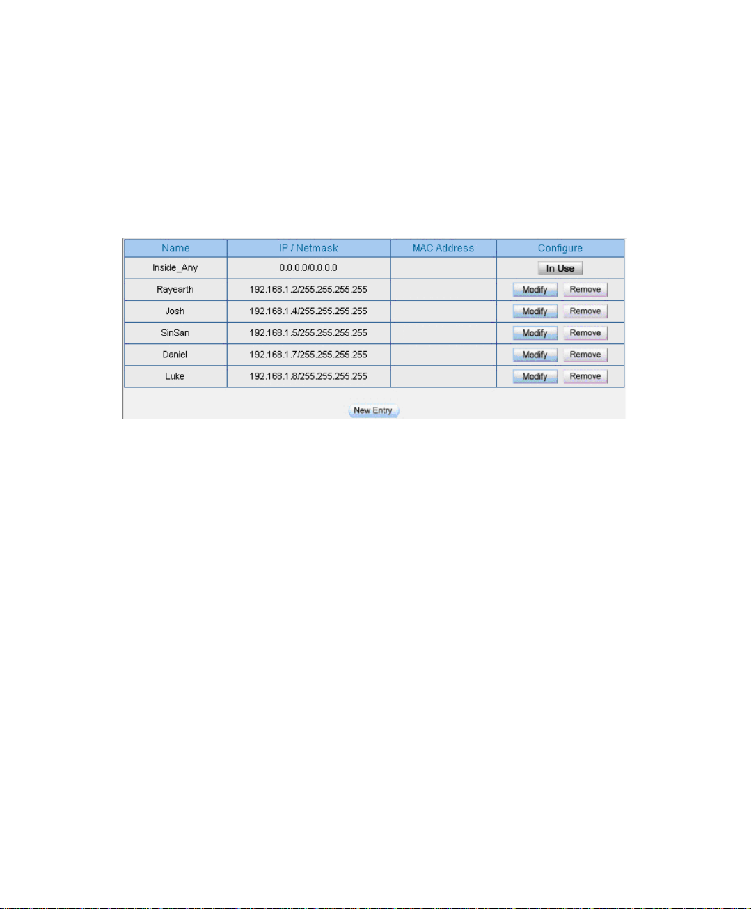
Step1 In AddressÆLAN , make the setting as following :
.
Click New Entry.
Name , enter the user’s identified name , Rayearth .
IP Address, enter the user’s IP 192.168.3.2 .
Netmask , enter 255.255.255.255 .
MAC Address , enter MAC address 00:B0:18:25:F5:89 .
Select Get static IP address from DHCP Server .
Click OK
LAN address setting
Complete the LAN address setting
63
Page 65

Step2. In Policy Æ Outgoing , add the new settings :
Limit the single user accessing the network resources through specific service
Step3. In Policy Æ Outgoing , to complete the settings to appointed the static IP
to the specific user and limit the user can only accessing FTP resources
through Policy .
Complete the settings to limit the single user accessing the network resources through policy
64
Page 66

When the MIS engineer set the Address settings , he can click ,in order to let the BM2101 can automatically copy the user’s network adapter MAC address .
In Address Æ LAN,the BM-2101 appliance will automatically set an Inside_Any Address,it
represents the whole LAN . The WAN or DMZ also has its Outside_Any and DMZ_Any default
address setting to represents its whole domain .
In AddressÆWAN and DMZ , the setting is the same as LAN . The only difference is that the
WAN can not set the MAC address .
65
Page 67
To set the policy which allow part of users connect to the remote static IPaddress.
Step1. Set many LAN address.
Set many LAN address
66
Page 68

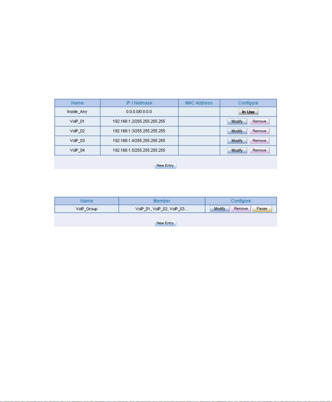
Step2. In Address Æ LAN Group , to set the setting as following :
Click New Entry.
To set the group Name .
In available address , select the user in the group and click Add .
Click OK .
Group the LAN address
Complete to group the LAN address
In AddressÆWAN Group and DMZ Group , the setting is the same as LAN Group .
67
Page 69

Step3. In Address Æ WAN , add the setting as following:
Click New Entry
Enter the remote static IP information . (Name , IP , Netmask)
Click OK
Set the WAN address
Complete to set the WAN address
68
Page 70

Step4. To apply Step 1~3 to Policy.
Apply the address setting in policy
Complete the policy setting
The Address function works by apply it to policy.
69
Page 71

Chapter 6
SSeerrvviiccee
The TCP Protocol and UDP Protocol can provide different services and every
service has its TCP port or UDP port number . For example , TELNET(23) , FTP(21),
SMTP(25) , POP3(110) , and so on . The Service function includes two parts : Predefined and Custom .
The Pre-defined included the common used and pre-identified TCP service or UDP
service .This kind of service can not be modified and canceled . On the other hand , the
user can set the proper TCP and UDP port number in Custom Service function.. When
sets the Custom Service function , the Client port number range is 1024 to 65535, the
server port is 0 to 65535 .
In this chapter , we will introduce the three common use services , for example ,
Pre-defined , Custom and Group. The MIS engineer can define the Protocol and port
number in every network applied communication by the following steps . The client
port can transfer the data by using different server.
How to use the Service ?
In Service Æ Group , the MIS engineer can add the new group name. In the
Group function , the MIS engineer can simply many process when setting the policy .
For example, there are 10 different IP address to access 5 different services via the
server, for example, such as the HTTP , FTP , SMTP , POP3 and TELNET . If the
MIS engineer do not use the Group function , he has to set 50 policy (10x5=50) .
Actually the MIS engineer only need to apply these services to the service group with
one policy.
70
Page 72

Service
Pre-defined
Icon The Definition
Any service .
TCP service , for example , FTP , FINGER , HTTP , HTTPS ,
IMAP , SMTP , POP3 , ANY , AOL , BGP , GOPHER ,
InterLocator , IRC , L2TP , LDAP , NetMeeting , NNTP ,
PPTPReal , Media , RLOGIN , SSH , TCP ANY , TELNET ,
VDO Live , WAIS , WINFRAME , X-WINDOWS .
UDP service , for example , IKE , DNS , NTP , IRC , RIP ,
SNMP , SYSLOG , TALK , TFTP , UDP-ANY , UUCP .
ICMP service , for example, PING , TRACEROUTE .
Service name
The MIS engineer can define the service name.
Protocol
The Protocol that is made of the communication between the devices. It included
the TCP and UDP mode .
Client Port
The Port number of the network adapter of the Client PC , the range is 1024 to
65535 , it is recommended to use the default range .
Server Port
The MIS engineer can enter the port number in Custom Service function.
71
Page 73

We set two environments.
No . Range The application environment
Example . 1
Custom
To permit the WAN user communicate to LAN user via the
network phone through policy . (VoIP port number:TCP
1720 , TCP 15328-15333 , UDP 15328-15333)
Example . 2
Group
To group the services , and limit the specific user accessing
the network resources which provided by the group service
through Policy.(Gruop:HTTP , POP3 , SMTP , DNS)
72
Page 74
6.1 Custom
To permit the WAN user communicate to LAN user via the network phone through
policy . (VoIP port number:TCP 1720 , TCP 15328-15333 , UDP 15328-15333)
Step1. In Address Æ LAN and LAN Group , add the following setting:
LAN address setting
Group the LAN address
73
Page 75
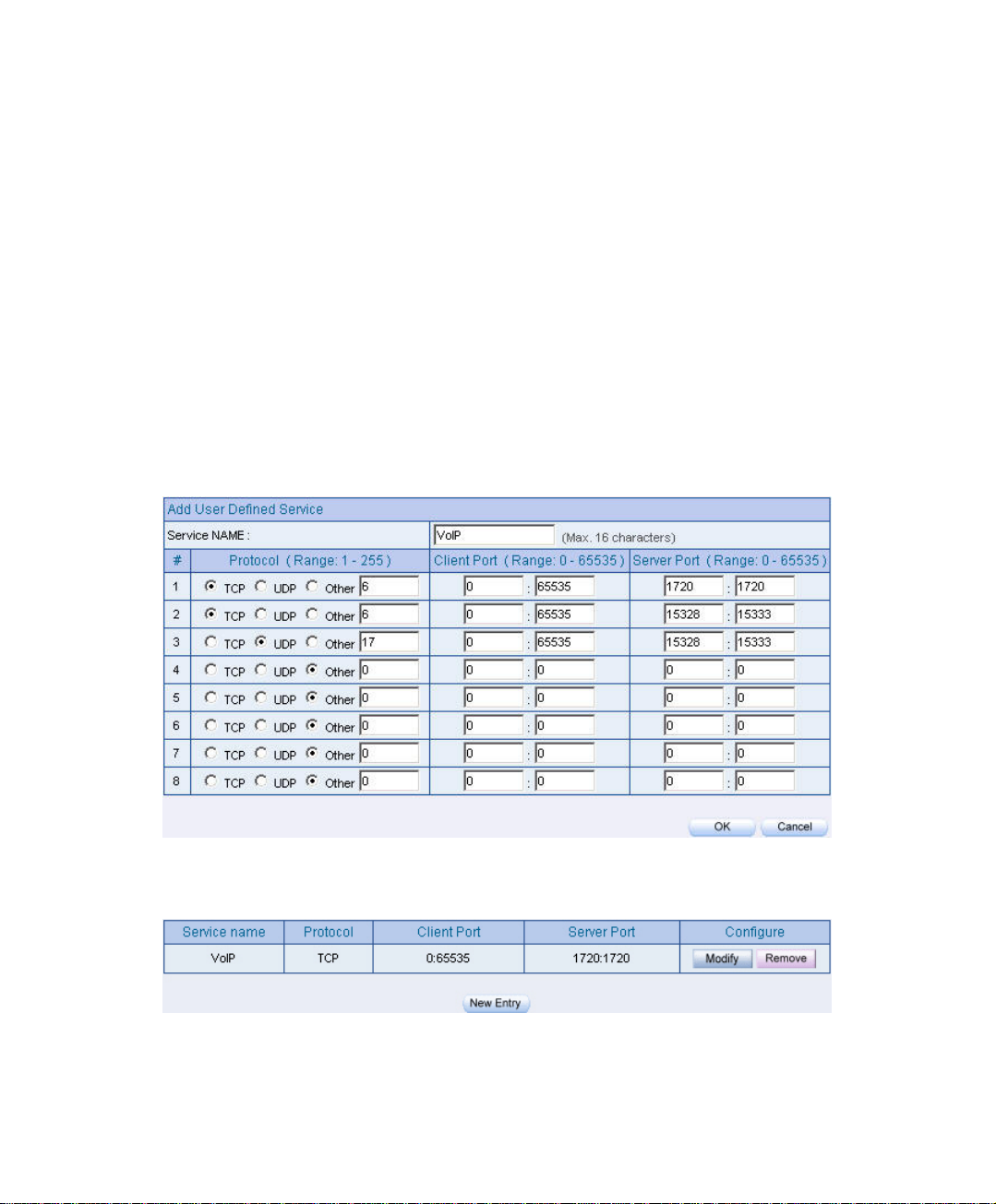
Step2. In Service Æ Custom add the setting as following :
Click New Entry .
Service NAME, enter the default name , VoIP .
Protocol # 1 , select TCP , Client Port ‘s setting reserve the default
value , Server Port , enter the value of 1720:1720 .
Protocol #2 , select TCP , Client Port ‘s setting reserve the default
value,Server Port , enter the value of 15328:15333 .
Protocol #3 , select UDP , Client Port ‘s setting reserve the default
value , Server Port , enter the value of 15328:15333 .
Click OK .
Custom setting
Complete the VoIP custom setting
74
Page 76

Normally,the default client port number is 0 to 65535. It is recommended not to modif y the port
number range in Custom Service function .
To enter the the port number in the client port , if the MIS engineer have to enter two different port
number in server port, then enter the range of 15328 :15333 . To enter the same port number in the server
port , the MIS engineer have to enter two same port number , for example, enter the range of 1720 : 1720.
75
Page 77
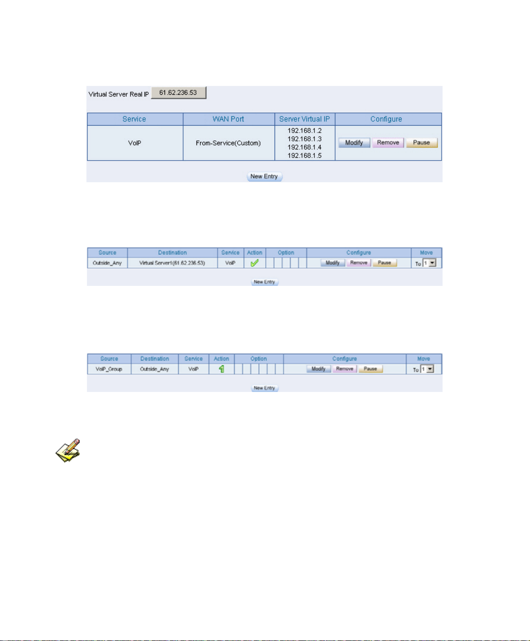
Step3. Apply the Service setting to Virtual Server .
Apply the service setting to virtual server
Step4. Apply Virtual Service to Policy Æ Incoming
Complete to set the incoming VoIP policy
Step5. In Policy Æ Outgoing , to complete the Outgoing VoIP setting .
Complete to set the outgoing VoIP policy
The service setting must apply to Policy and Virtual Server,to make it real working .
76
Page 78
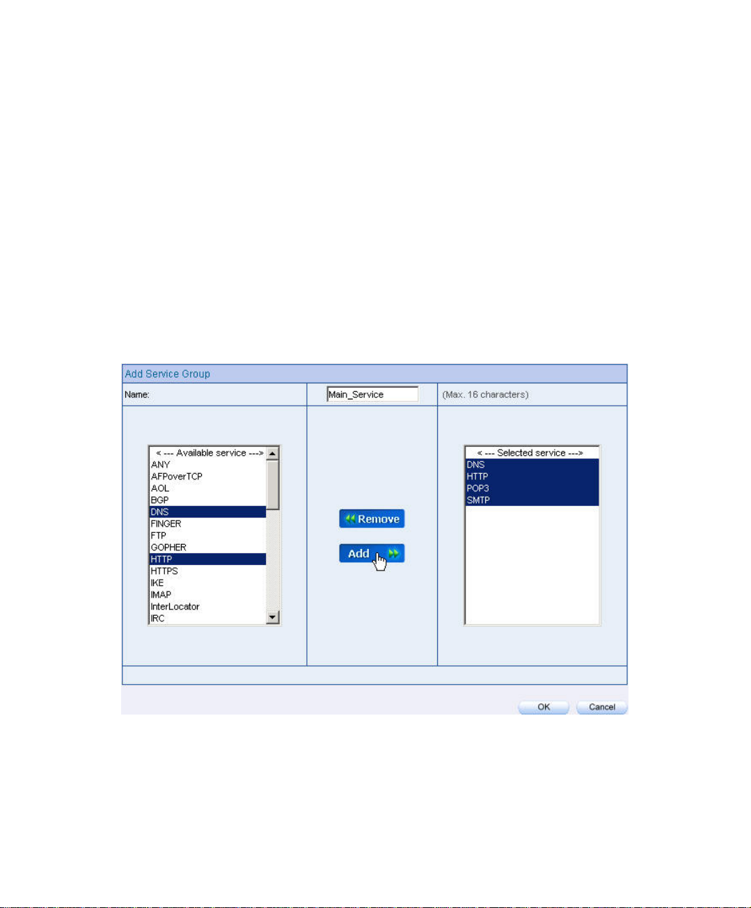
6.2 Group
To Group the Service , and limit the user can only access the Network resources
provided by the Group through Policy Object . (Group:HTTP , POP3 , SMTP ,
DNS)
Step1. In Service Æ Group , add the new setting as following:
Click New Entry .
Set the Name to be the default name of Main_Service .
In Available service , select HTTP , POP3 , SMTP , DNS , Click Add.
Click OK .
Service group setting
77
Page 79
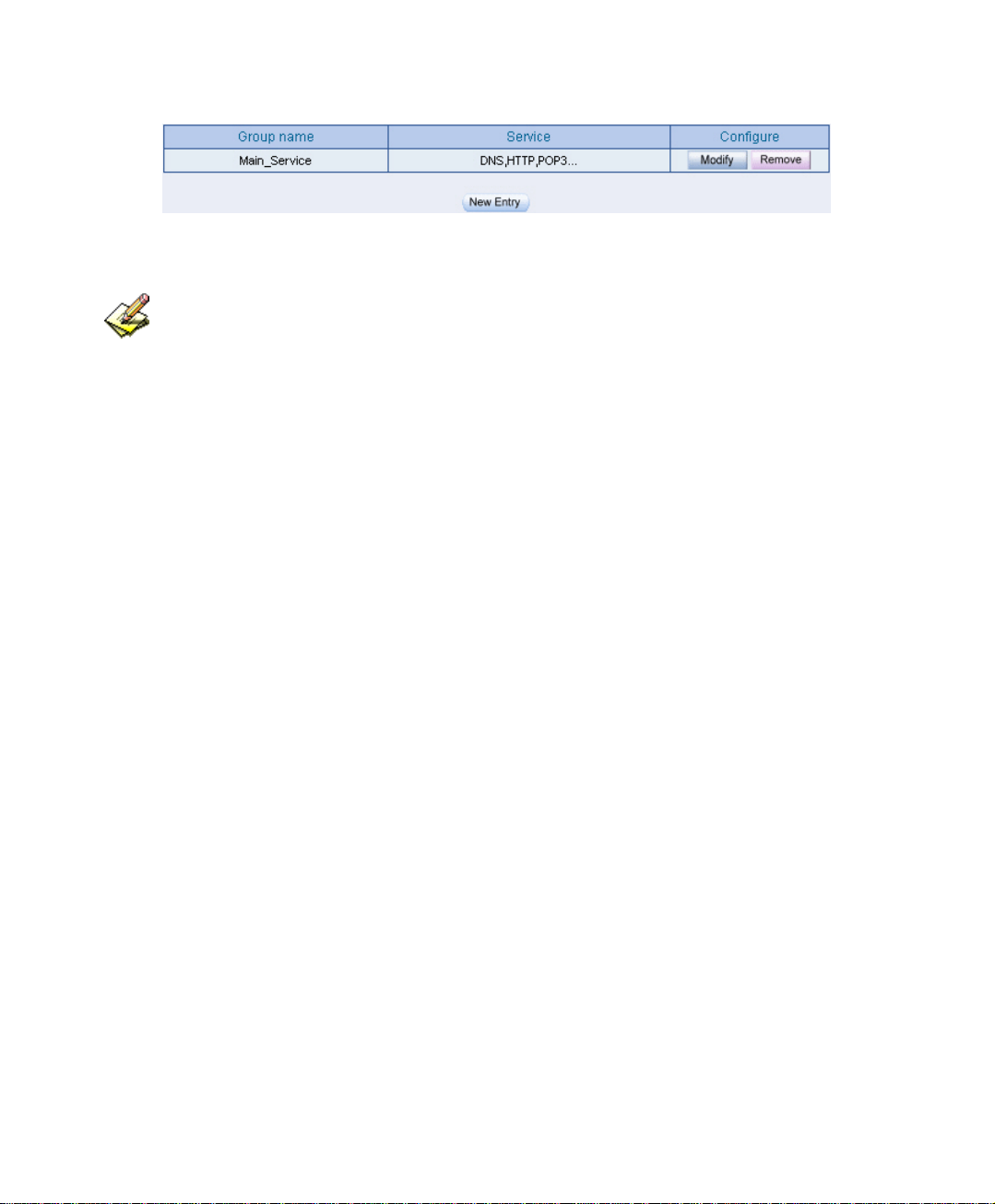
Complete the service group setting
If the MIS engineer want to remove the group service , then he can choose the Selected service ,
and click Remove .
78
Page 80

Step2. In Address Æ LAN Group, to set the LAN group ,which can only access
the specific service.
LAN group setting
Step3. Apply Service Group to Policy Æ Outgoing .
Policy setting
79
Page 81

Chapter 7
SScchheedduullee
In this chapter , the MIS engineer can difine the network connection and the
process time period in Schedule. In other words , the MIS engineer can select the
specific time period to transfer the data packets by policy management.
How to use Sehedule ?
The MIS engineer can use the Schedule function to auto set the packets flow in
different time period by Policy management.
80
Page 82
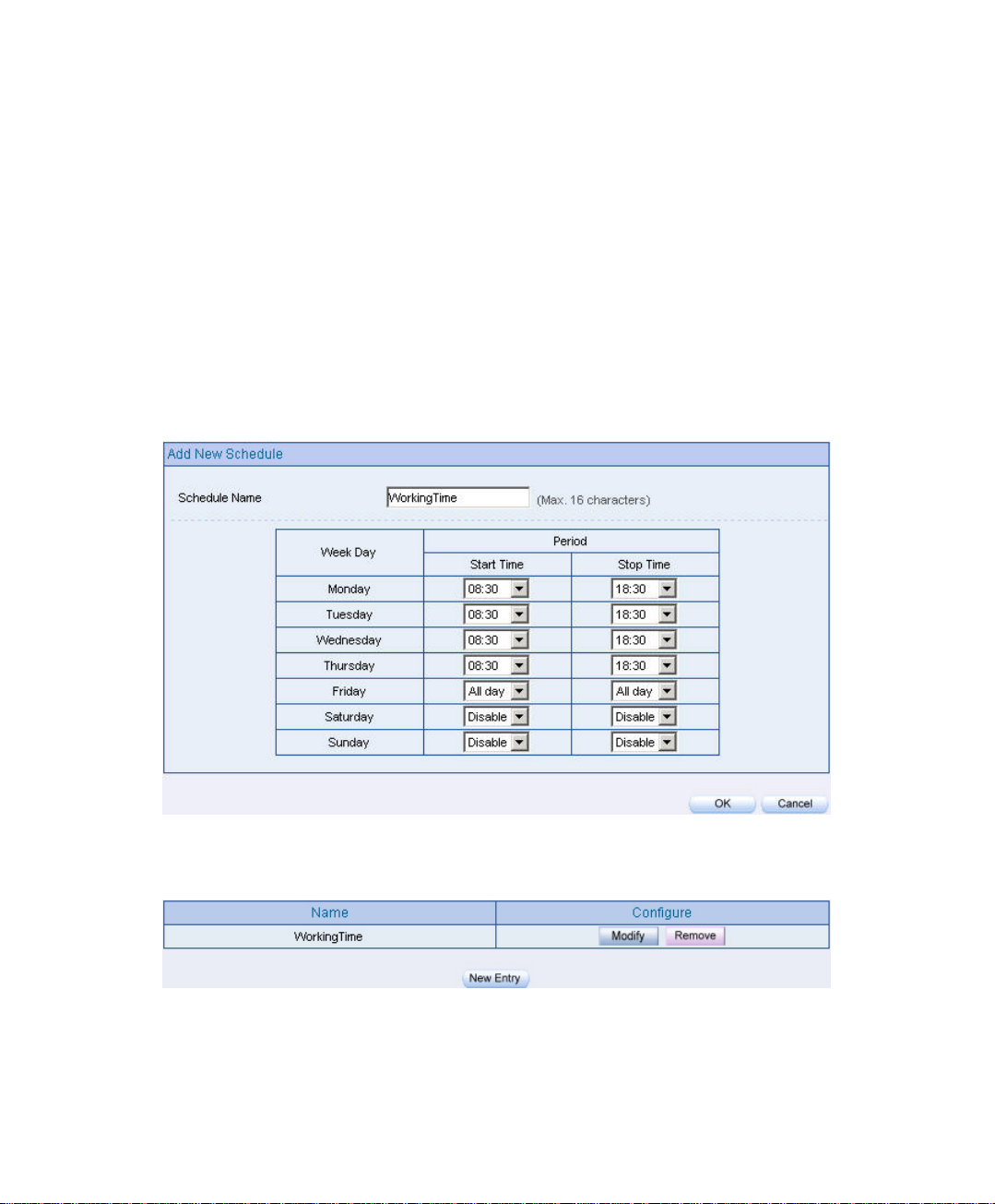
To set the valid time of LAN user can access the network data everyday through the
policy management.
Step1. In Schedule , add the new setting as following:
Click New Entry
Set the Schedule Name .
Use the drop down menu to select the time period everyday .
Click OK
Schedule setting
Complete the schedule setting
81
Page 83

Step2. Apply schedule setting to Policy Æ Outgoing
Complete to apply the schedule setting to policy
The Schedule setting must apply into Policy.
82
Page 84

Chapter 8
QQooSS
The BM-2101 appliance can manage the downstream and upstream bandwidth
through the bandwidth parameter setting .
The MIS engineer can set the bandwidth depends on the provided WAN bandwidth.
Downstream Bandwidth: Can set the G.Bandwidth and M.Bandwidth .
Upstream Bandwidth:Can set the G.Bandwidth and M.Bandwidth .
QoS Priority:Can set the QoS priority of upstream and downstream bandwidth .
The BM-2101 appliance can set the outgoing bandwidth depends on different QoS ,
and can select the proper QoS setting by policy . It can let the MIS engineer efficiently
to distribute the bandwidth.
Unused QoS Flow
83
Page 85

The used QoS Flow(M.Bandwidth:400 Kbps , G.Bandwidth:200Kbps)
84
Page 86

QoS
WAN
Includes WAN 1 and WAN 2.
Downstream Bandwidth
The maximum bandwidth and guarantee bandwidth of downstream bandwidth.
Upstream Bandwidth
The maximum bandwidth and guarantee bandwidth of upstream bandwidth.
QoS Priority
To set the unuse upstream and downstream bandwidth in QoS priority .
G.Bandwidth
The basic bandwidth in QoS. The policy which applied to the QoS , will at least
reserve the QoS settings .
M.Bandwidth
The maximum bandwidth in QoS. The Policy which applied to the QoS, its
bandwidth will not over the QoS Setting .
85
Page 87

8.1 Example
To set the Policy of the Upstream Bandwidth and Downstream Bandwidth .
Step1. In QoS , add the new setting as following :
Click New Entry
In Name, to set the QoS name.
In WAN 1 , 2 , enter the parameter of limited bandwidth .
To select the QoS Priority.
Click OK .
QoS setting
Complete the QoS setting
86
Page 88

Step2. In Policy Æ Outgoing , to apply the QoS Setting in Step 1
Set the QoS policy
Complete to set the QoS policy
When the MIS engineer setting the QoS , he must use the correct upstream and downstream
bandwidth range set in interface Æ WAN.
87
Page 89

Chapter 9
AAuutthheennttiiccaattiioonn
The BM-2101 appliance can manage the user’s connection by authentication. The
user has to pass the authentication to connect the network .
The BM-2101 appliance provided 4 authentication modes . The User and User
Group built in ; others are RADIUS , POP3 and LDAP self-built Authentication
Server. The MIS engineer can use the 5 modes , to manage the authentication.
88
Page 90

Authentication
Authentication Management
It can provide the authentication port to the MIS engineer and the valid
authentication time . (The MIS engineer has to set the Authentication function
first .)
Authentication Port:When enable the Authentication, the LAN user must
pass the authentication to login to the WAN. And the authentication port
number is the default value of 82 .
Re-Login if Idle:When the LAN user connect to the WAN , the MIS
engineer can set the Idle time after the Authentication. When the login Idle
time has over the default Idle time settings of 30 minutes . The authenticaion
will automatically invalid .
Re-Login after user login successfully:When the LAN user connect to the
WAN through the authentication . The available authentication time depends
on the time limit , if over the default time setting , the authentication will be
invalid .
Disallow Re-Login if the auth user has login:When enable this function
through User ,User Group , RADIUS , POP3 or LDAP to access the
authenticaion , the authorized account can not be used by other people .
URL to redirect when authentication succeed:To direct the authorized
LAN user to the assigned web site . The default value is blank . (It will
directly link the user to the login web site .
Messages to display when user login:It shows the login messages in the
authentication window ( it supports the HTML ) , the default setting is blank
(it will not show any massage in the authenication window.)
89
Page 91

z To add the settings in the authenticaion management :
Authentication management
90
Page 92

When the user connect to the WAN through the authentication , it shows the following
window :
Login Authentication
After the authentication , it will redirect to the assigned web site.
If the user want to require the authentication , then he can enter the BM-2101’s LAN interface IP
and the authenticaion port number in the URL address , then shows the authentication window.
Authenticatoin- User Name
The user’s authentication account.
Password
Create the authentication password.
Confirm Password
91
Page 93

To enter the same password as in the password column .
Shared Secret
The required password when accessing the authentication between the BM-2101
appliance and RADIUS server .
802.1x RADIUS
The authentication between the BM-2101 appliance and RADIUS server which
included the wireless network.
Search Distinguished Name
The identify name of LDAP server .
LDAP Filter
To assign the specific account in LDAP server.
User Distinguished Name
The required account in the authentication between the BM-2101 appliance and
LDAP server .
92
Page 94

We set 4 environments.
No. Range The Application Environments
Example 1
User
User
To plan the LAN user connect to the WAN through the
authenticaton by policy . (To use the built-in user and user
group authentication.)
Group
Example 2
RADIUS
To plan the user connect to the WAN through the
authenticaton in policy .To use the WAN RADIUS server
(Windows 2003 Server built-in authentication .)
Example 3
POP3
To plan the user connect to the WAN through the
authenticaton by policy.( To use the WAN POP3 server
authentication )
Example 4
LDAP
To plan the user connect to the WAN through the
authenticaton by policy .(To use the WAN LDAP server
(Windows 2003 Server built-in authentication)
93
Page 95
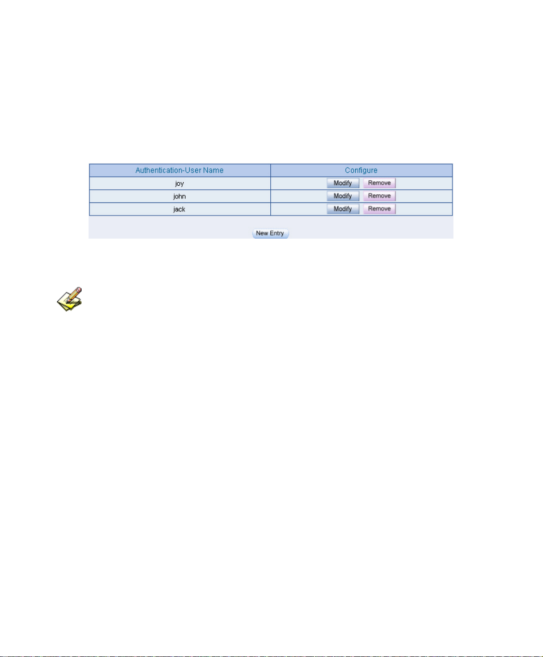
9.1 User / User Group
To plan the LAN user connect to the WAN through the authenticaton by policy . (To
use the built-in user and user group authentication.)
Step1. In Authentication Æ User , to add the Authentication –User Name.
Set the authentication user
The user’s DNS server must correspond to the LAN interface through the BM-2101 appliance , in
order to enable the authentication .
94
Page 96

Step2. In Authentication Æ User Group , add the new setting as following:
Click New Entry .
Name, enter laboratory.
Click Add, to add the available authentication user to the selected
authentication user in the same user group .
Click OK .
Complete the user group settings in authentication.
Authenticatoin setting
95
Page 97
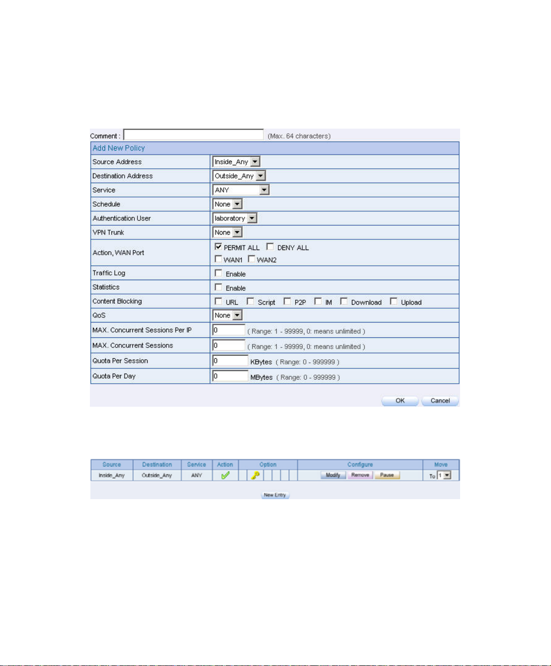
Step3. In Policy Æ Outgoing, add a new policy , and apply the Step 1, 2 into the
new policy setting .
Authentication user policy setting
Complete the policy setting
96
Page 98

. Step4 When the LAN user want to connect to the network via browser , it will
shows the authentication window. After enter the correct user name and
password, Click OK , to connect to the network via the BM-2101 appliance
To create the IPSec VPN connection via the authentication
Step5 If the remote user want to logout , click Logout Auth-User in Auth-User
.
Logout window(The logout window will appear when pass the
authentication ), the MIS engineer can also log in Auth-User Logout
window(http:// LAN Interface:Authentication Port / logout.html),
click Logout Auth-User .
.
Logout confirmation
97
Page 99

9.2 RADIUS
To plan the user connect to the WAN through the authenticaton in policy .To use the
WAN RADIUS server(Windows 2003 Server built-in authentication .)
※ Windows 2003 RADIUS Server Deployment
Step1. Click Start Æ Control Panel Æ Add / Remove Programs , select Add /
Remove Windows Components , then it shows the Windows Comonents
Wizard .
Step2. Select Networking Services , then click Details .
Windows Components Wizard
98
Page 100

Step3. Select Internet Authentication Service
Add new network authentication service components
99
 Loading...