

Page 1
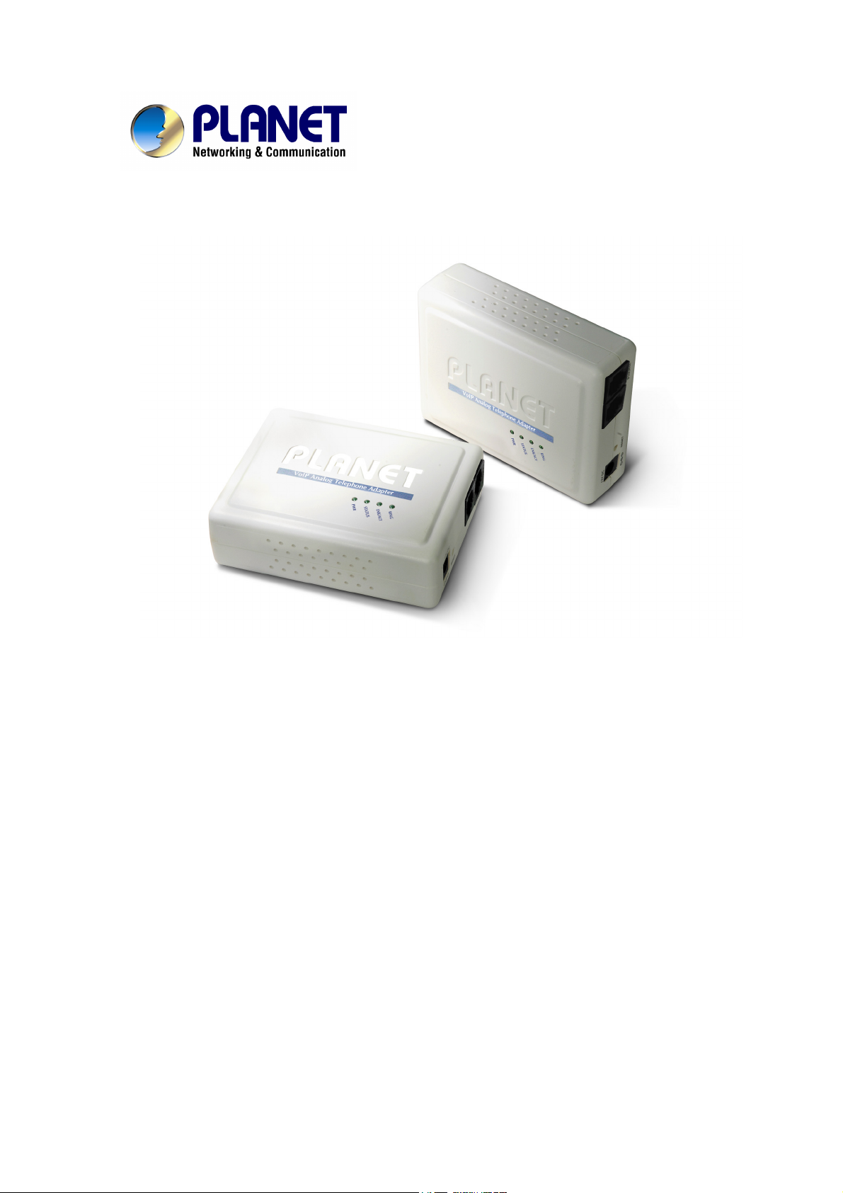
VoIP Analog Telephone Adapter
ATA-150/ATA-150S
User’s manual
Version 1.1
- 1 -
Page 2

Copyright
Copyright (C) 2010 PLANET Technology Corp. All rights reserved.
The products and programs described in this User’s Manual are licensed products of PLANET Technology, This
User’s Manual contains proprietary information protected by copyright, and this User’s Manual and all
accompanying hardware, software, and documentation are copyrighted.
No part of this User’s Manual may be copied, photocopied, reproduced, translated, or reduced to any electronic
medium or machine-readable form by any means by electronic or mechanical. Including photocopying, recording,
or information storage and retrieval systems, for any purpose other than the purchaser's personal use, and without
the prior express written permission of PLANET Technology.
Disclaimer
PLANET Technology does not warrant that the hardware will work properly in all environments and applications,
and makes no warranty and representation, either implied or expressed, with respect to the quality, performance,
merchantability, or fitness for a particular purpose.
PLANET has made every effort to ensure that this User’s Manual is accurate; PLANET disclaims liability for any
inaccuracies or omissions that may have occurred.
Information in this User’s Manual is subject to change without notice and does not represent a commitment on the
part of PLANET. PLANET assumes no responsibility for any inaccuracies that may be contained in this User’s
Manual. PLANET makes no commitment to update or keep current the information in this User’s Manual, and
reserves the right to make improvements to this User’s Manual and/or to the products described in this User’s
Manual, at any time without notice.
If you find information in this manual that is incorrect, misleading, or incomplete, we would appreciate your
comments and suggestions.
CE mark Warning
The is a class B device, In a domestic environment, this product may cause radio interference, in which case the
user may be required to take adequate measures.
Energy Saving Note of the Device
This power required device does not support Stand by mode operation.
For energy saving, please remove the DC-plug or push the hardware Power Switch to OFF position to disconnect
the device from the power circuit.
Without remove the DC-plug or switch off the device, the device will still consuming power from the power circuit. In
the view of Saving the Energy and reduce the unnecessary power consuming, it is strongly suggested to switch off
or remove the DC-plug for the device if this device is not intended to be active.
WEEE Warning
To avoid the potential effects on the environment and human health as a result of the presence of
hazardous substances in electrical and electronic equipment, end users of electrical and electronic
equipment should understand the meaning of the crossed-out wheeled bin symbol. Do not dispose of
- 2 -
Page 3

WEEE as unsorted municipal waste and have to collect such WEEE separately.
Trademarks
The PLANET logo is a trademark of PLANET Technology. This documentation may refer to numerous hardware
and software products by their trade names. In most, if not all cases, their respective companies claim these
designations as trademarks or registered trademarks.
Revision
User’s Manual for PLANET VoIP Analog Telephone Adapter:
Model: ATA-150 / ATA-150S
Rev: 1.1 (2010, October)
Part No. EM-ATA150 Series
- 3 -
Page 4

TABLE OF CONTENTS
Chapter 1 Introduction ............................................................................................................6
Overview....................................................................................................................................................... 6
Package Content .......................................................................................................................................... 7
Physical Details ............................................................................................................................................7
Physical Interface & Button ................................................................................................................. 8
Chapter 2 Preparations & Installation.................................................................................10
Physical Installation Requirement............................................................................................................10
Keypad commands ............................................................................................................................. 11
Chapter 3 TCP/IP Settings..................................................................................................... 14
Configuring and monitoring your ATA from web browser .................................................................... 14
Overview on the web interface of ATA ..............................................................................................14
Manipulation of ATA via web browser............................................................................................... 14
LAN IP address configuration via web configuration interface ......................................................... 15
Chapter 4 VoIP Settings .........................................................................................................21
Phone 1 / Phone 2 (ATA-150S) ..........................................................................................................21
Tone .................................................................................................................................................... 30
Other................................................................................................................................................... 32
Auto Config........................................................................................................................................ 33
Chapter 5 Management .........................................................................................................35
Status.................................................................................................................................................. 35
Statistics .............................................................................................................................................35
DDNS................................................................................................................................................. 35
Time Zone Setting.............................................................................................................................. 36
Denial-of-Service ............................................................................................................................... 37
Log .....................................................................................................................................................38
Upgrade Firmware.............................................................................................................................. 38
Save / Reload Settings........................................................................................................................ 39
Password Setup .................................................................................................................................. 39
Reboot ................................................................................................................................................ 39
Logout ................................................................................................................................................ 40
Appendix A Voice communication samples.............................................................................................. 41
Peer to peer (P2P) mode..................................................................................................................... 41
Case 2: (Peer-to-Peer mode) ATA-150S Port 1 to Port 2 communications......................................... 41
Case 3: SIP Proxy mode .....................................................................................................................42
Case 4: Call Forward Feature_Example 1..........................................................................................43
Case 5: Call Forward Feature_Example 2..........................................................................................45
Appendix B The method of operation guide............................................................................................ 46
- 4 -
Page 5

Call Transfer....................................................................................................................................... 46
3-Way Conference .............................................................................................................................. 46
Call Waiting........................................................................................................................................ 46
Switch the Default Proxy ...................................................................................................................46
Auto Update firmware by manual (Keypad)...................................................................................... 47
Appendix C Frequently Asked Questions List ........................................................................................ 48
Appendix D ATA Specifications ................................................................................................................ 49
- 5 -
Page 6

Chapter 1
1
1
Introduction
Overview
Based on years of VoIP manufacturing experiences, PLANET Technology VoIP total solutions are
known for advanced implementation of standards based telephony with mass deployment capability.
Cost-effective, easy-to-install and simple-to-use, the PLANET ATA-150/ATA-150S VoIP Phone Adapter
(“ATA” in the following term) converts standard telephones to IP-based networks. The service providers
and enterprises can offer users traditional and enhanced the telephony communication services via the
existing broadband connection to the Internet or corporation network.
With the ATA, home users and companies are able to save the installation cost and extend their past
investments in telephones, conference and speakerphones. The ATA equipped with two telephony
interfaces, users may register to different SIP proxy servers, IP PBX and establish up to 2 concurrent
VoIP calls for more flexibility in the voice communications. ATA can be the bridge between the
traditional analog telephones to IP network with an extremely affordable investment.
Product Features
• Feature-rich telephone service over home Internet / Intranet connection
• Up to 2 concurrent VoIP calls
• Cost-effective, easy-to-use solution for Analog Telephone Adapter
• Web-based utility and machine configuration
• Remote administrator authentication
• Voice prompt for machine configurations
VoIP Features
• SIP 2.0 (RFC3261) compliant
• Voice codec: G.711(A-law /μ-law),G.729 AB, G.723 (6.3 Kbps / 5.3Kbps)
• FoIP : T.38 FAX Relay, G.711 Fax pass-through
• QoS : IP TOS (IP Precedence) / DiffServ
• Call Waiting / Hold / Resume / Transfer / Forward /
• 3-Way Conference / Caller ID Generation
• VAD / CNG / Dynamic Jitter Buffer
• SNMP v1/v2, TR-069 and Auto Provision
- 6 -
Page 7

Package Content
The contents of your product should contain the following items:
VoIP Telephone Adapter
Power adapter
Quick Installation Guide
User’s Manual CD
RJ-11 cable x 1
Physical Details
The following figure illustrates the each panel of SIP ATA.
ATA-150: SIP Analog Telephone Adapter (1 x RJ-45, 1 x RJ-11)
ATA-150S: 2-Port FXS SIP Analog Telephone Adapter (1 x RJ-45, 2 x RJ-11)
Front Panel of ATA-150
Left / Right Panel of ATA-150
- 7 -
Page 8

Front Panel of ATA-150S
Left / Right Panel of ATA-150S
Physical Interface & Button
Pressing 1 second to reboot machine.
1 RESET
Pressing 5 seconds to reset to the factory default setting
2 12V DC
3 LAN
4 Phone
- 8 -
12V DC Power input outlet
RJ-45 connector, for Internet access, connected directly to
Switch/Hub through straight CAT-5 cable.
RJ-11 connector, connected directly to the analog phone.
Page 9

LED Display of ATA-150
PWR
LNK/ACT
Phone
LED Display of ATA-150S
PWR
LNK/ACT
RING1
RING2
Power is supplied to the device.
OFF: the device is disconnected to LAN.
ON: the device is connected to LAN.
OFF: the phone is idle.
ON: the phone is in use (off-hook).
Blinking: the phone is ringing.
Power is supplied to the device.
OFF: the device is disconnected to LAN.
ON: the device is connected to LAN.
OFF: the phone is idle.
ON: the phone is in use (off-hook).
Blinking: the phone is ringing.
OFF: the phone is idle.
ON: the phone is in use (off-hook).
Blinking: the phone is ringing.
Í
Note
1. Machine default IP is http://192.168.0.1. Press RESET
button on rear panel over 5 seconds will reset the VoIP
Phone Adapter to factory default value. (Except speed
dial and call forward settings)
2. Using the power supply that is not the one included in
package will cause damage and void the warranty for this
product.
3. Be noted to use the switching type power supply for
regular operating.
- 9 -
Page 10
Chapter 2
2
Preparations & Installation
Physical Installation Requirement
This chapter illustrates basic installation of ATA analog Phone Adapter (“ATA” in the following term)
• Network cables. Use standard 10/100Base-TX network (UTP) cables with RJ-45 connectors.
• TCP/IP protocol must be installed on all PCs.
For Internet Access, an Internet Access account with an ISP, and either of a DSL or Cable modem
Administration Interface
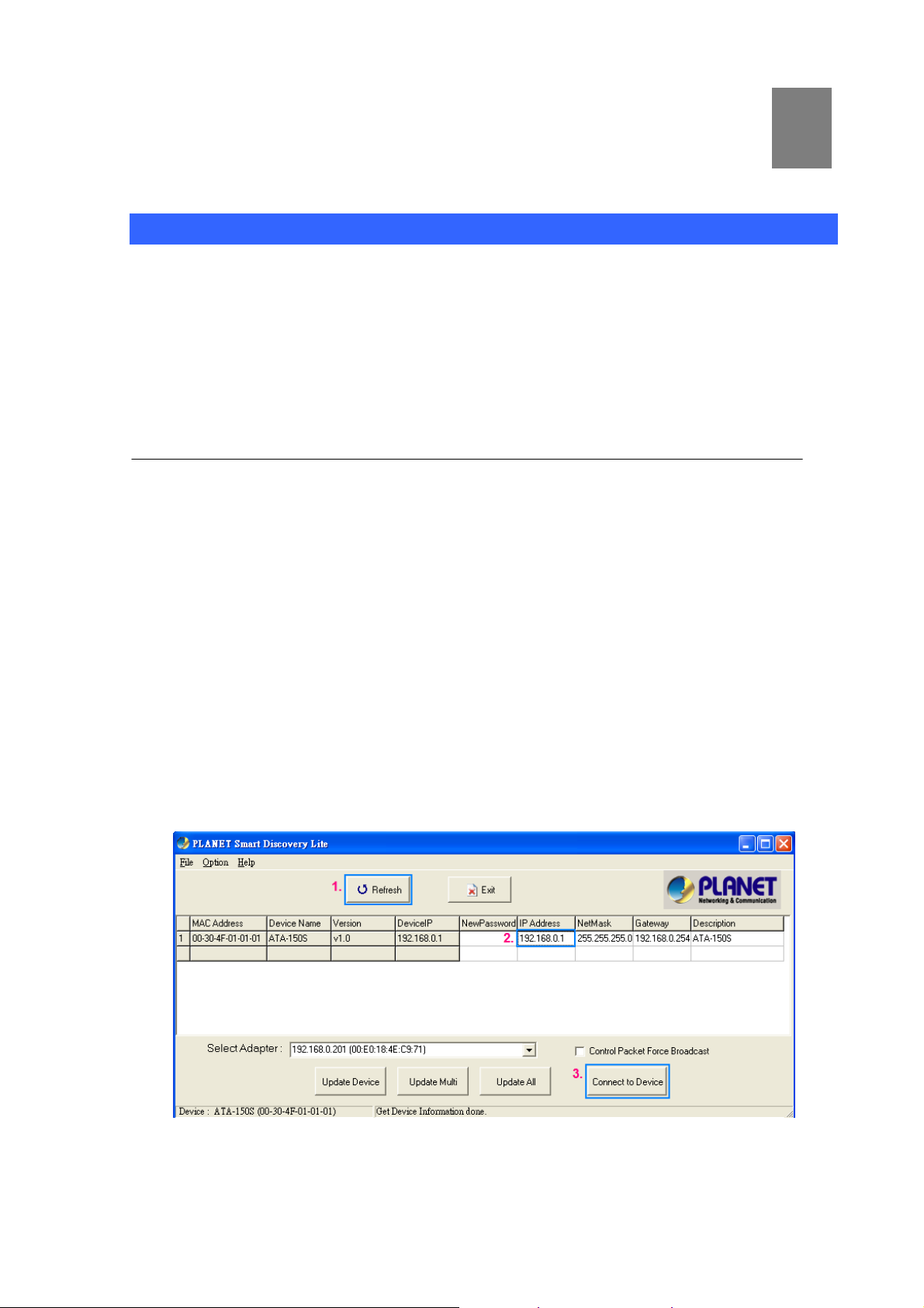
PLANET ATA provides GUI (Web based, Graphical User Interface) and utility for machine management
and administration.
Utility quickly search access
Using for soft utility to search SIP ATA from current network. The utility not only easy-to-use and
provides user more convenience for configuration access, at the some time If you forget this IP address
can also found that via the utility.
Copy this utility tool in your laptop or desktop computer first. And, this utility tool can only be executed in
Windows series of operating systems.
Click the icon for windows desktop to start searching ATA in the network.
Select “Refresh” and you will get the results as above choose the device you want to configuration,
click this IP address of ATA and press the “Connect to Device” button to browse the web page.
- 10 -
Page 11
Web configuration access
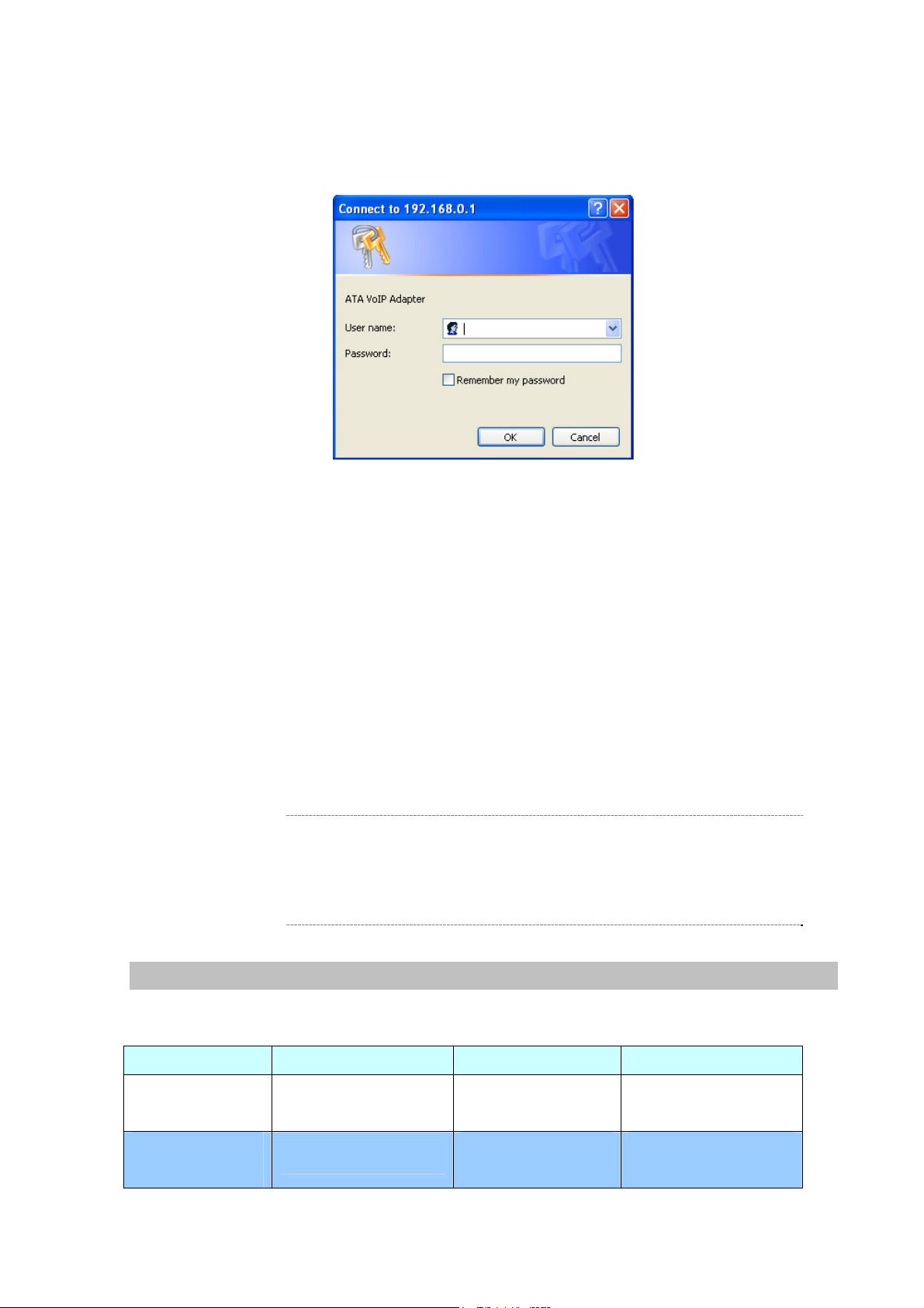
You will connect to SIP ATA via your web browser automatically. ATA will prompt for logon username /
password, please enter: admin / 123 to continue machine administration.
ATA will prompt for logon username/password, please enter: admin / 123 to continue machine
administration.
The default IP address of ATA is 192.168.0.1. You also could open your web browser, and insert
http://192.168.0.1 in the address bar of your web browser to logon ATA web configuration page.
To start ATA web configuration, you must have one of these web browsers installed on computer for
management
•
Microsoft Internet Explorer 6.00 or higher with Java support
Please locate your PC in the same network segment
Í
Note
(192.168.0.x) of ATA. If you’re not familiar with TCP/IP,
please refer to related chapter on user’s manual CD or
consult your network administrator for proper network
configurations.
Keypad commands
The ATA series phone adapters support telephone keypad configurations, please connect analog
telephone set and refer to the following table for machine network configurations.
IVR Menu Choice Machine operation Parameter(s) Notes
#111#
#112xxx*xxx*xxx*
xxx#
- 11 -
Set DHCP client None
Use the * (star) key
Setup Static IP Address
when entering a decimal
ATA will change to DHCP
Client
DHCP will be disabled and
system will change to the
Page 12

point. Static IP type.
#113xxx*xxx*xxx*
xxx#
#114xxx*xxx*xxx*
xxx#
#115xxx*xxx*xxx*
xxx#
#190#
#195#
Use the * (star) key
Set Network Mask
Set Gateway IP Address
Set Primary DNS Server
Unlock None
Save Network Settings None
when entering a decimal
point.
Use the * (star) key
when entering a decimal
point.
Use the * (star) key
when entering a decimal
point.
Must set Static IP first.
Must set Static IP first.
Must set Static IP first.
Must unlock the protect
function before carry out
the firmware update
(#160#).
Must save network
settings after set up
network settings via
keypad.
The system will be reset to
#198#
Factory Reset None
factory default value and
reboot automatically.
Following keypad commands can be used to display the network settings enabled on ATA via voice
prompt.
IVR Menu Choice Machine operation Notes
#120#
#121#
#122#
#123#
Check IP Address
Check network connection Type
Check the Phone Number
Check Network Mask
IVR will announce the current IP address of
the ATA.
IVR will announce if DHCP in enabled or
disabled.
IVR will announce current enabled VoIP
number.
IVR will announce the current network mask
of the ATA.
#124#
#125#
#128#
Check Gateway IP Address
Check DNS Server Setting
Check Firmware Version
IVR will announce the current gateway IP
address of the ATA.
IVR will announce the current setting in the
DNS field.
IVR will announce the version of the
firmware running on the ATA.
- 12 -
Page 13

Following keypad commands can be used to set up the main function .
IVR Menu Choice Machine operation Parameter(s) Notes
01: G.711 u-Law, 02:
#130+first
priority codec
#133#
#134#
#138#
#139#
#140+Forward
type+Forward
Phone Number#
G.711 a-Law, 03: G.729,
04: G.723 6.3K, 05:
Set First Priority Codec
Set Speaker Voice Gain 00~31, 32: Mute
Set Mic Voice Gain 00~31, 32: Mute
Enable call waiting None Enable Call waiting
Disable call waiting None Disable Call waiting
Forward Settings
G.723 5.3K, 06: G.726
16K, 07: G.726 24K, 08:
G.726 32K, 09: G.726
40K, 10: GSM-FR
Forward Type:
1: Immediate Forward
2: Busy Forward
3: No answer Forward
You can set the codec you
want to the first priority.
For example: #13001#
Set G.711 u-Law to the first
priority codec
For example: #13305#
Mic Voice: 5
For example: #13410#
Mic Voice: 10
For example: #1401101#
Immediate Forward to 101
#141#
#150#
#160#
Disable Forward Settings None
For example: #1501#
Select Default Realm 0: Realm 1, 1: Realm 2
Set Default Proxy to Realm 2
Update firmware
Must unlock the protect
Update firmware None
function (#190#) before carry
out the firmware update.
- 13 -
Page 14

Chapter 3
3
TCP/IP Settings
Configuring and monitoring your ATA from web browser
The ATA integrates a web-based graphical user interface that can cover most configurations and
machine status monitoring. Via standard web browser, you can configure and check machine status
from anywhere around the world.
Overview on the web interface of ATA
With web graphical user interface, you may have:
More comprehensive setting feels than traditional command line interface.
Provides user input data fields, check boxes, and for changing machine configuration settings
Displays machine running configuration
To start ATA web configuration, you must have one of these web browsers installed on computer for
management
Microsoft Internet Explorer 6.00 or higher with Java support
Manipulation of ATA via web browser
Log on ATA via web browser
After TCP/IP configurations on your PC, you may now open your web browser, and input
http://192.168.0.1
Enter the IP address of the ATA which
by default is 192.168.0.1
Phone Adapter will prompt for logon username/password: admin / 123
to logon Phone Adapter web configuration page.
ATA login prompt screen
- 14 -
Page 15
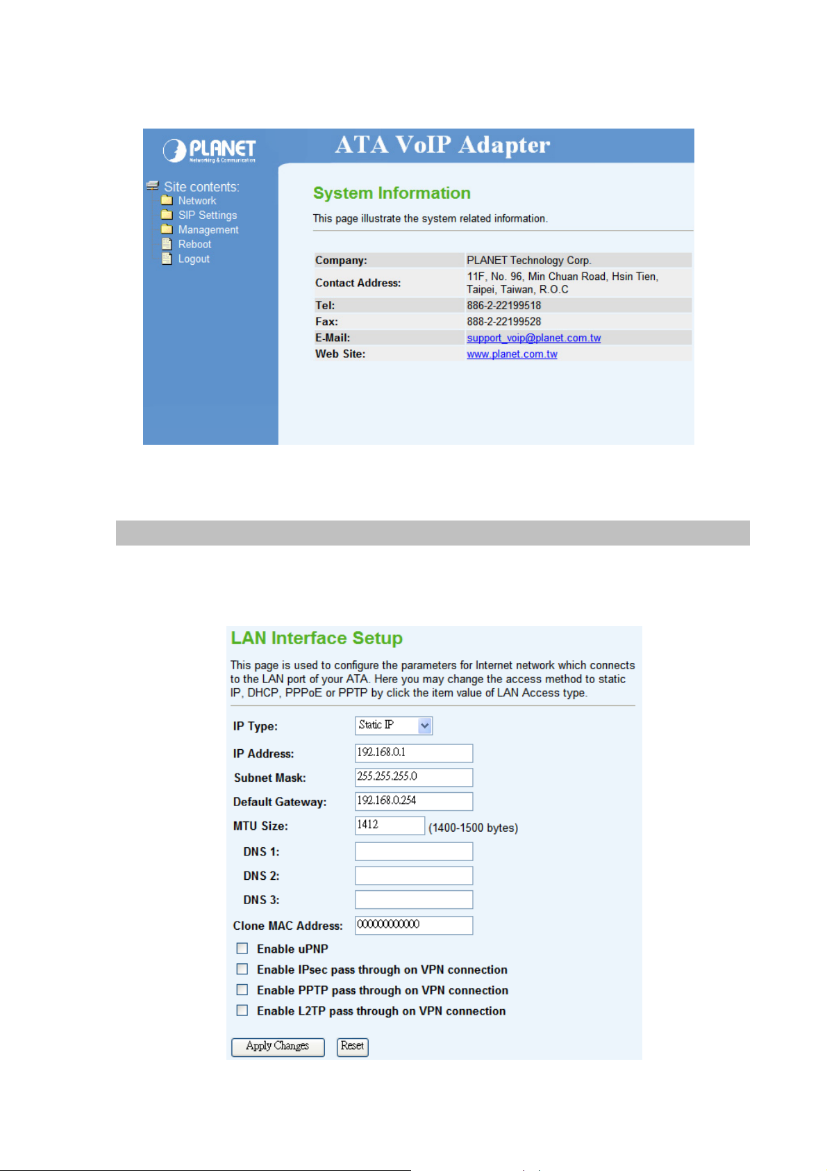
When users login the web page, users can see the Phone Adapter system information like firmware
version, company…etc in this main page.
VoIP Phone Adatper main page
LAN IP address configuration via web configuration interface
This page is used to configure the parameters for Internet network which connects to the LAN port of
your ATA. Here you may change the access method to static IP, DHCP, PPPoE or PPTP by click the
item value of LAN Access type.
- 15 -
Page 16

Connection Type Description – Static IP
Static IP
IP Address
Subnet Mask
Default Gateway
MTU Size
DNS1/ 2/ 3
Clone MAC Address
Enable uPnP
Set LAN interface as Static IP mode.
LAN IP Address of the ATA
Default : 192.168.0.1
LAN mask of the ATA
Default : 255.255.255.0
Gateway of the ATA
Default : 192.168.0.254
Set MTU (maximum transmission unit) size
Default : 1412
Set three alternative Domain Name Server for LAN interface.
Default : Null
To clone the MAC by manual input.
Default : 000000000000 (Null)
Check to enable UPnP function
Enable IPsec pass through on
VPN connection
Enable PPTP pass through on
VPN connection
Enable L2TP pass through on
VPN connection
Default : Disable
Check to enable IPsec function
Default : Enable
Check to enable PPTP pass through function
Default : Enable
Check to enable L2TP pass through function
Default : Enable
- 16 -
Page 17

Connection Type Description – DHCP Client
DHCP Client
Attain DNS Automatically /
Set DNS Manually
Set LAN interface as DHCP mode.
Select to attain DNS automatically from server or user wants to
set DNS manually.
Default : Set DNS Manually
- 17 -
Page 18

Connection Type Description – PPPoE
PPPoE
User Name
Password
Service Name
Connection Type
Set LAN interface as PPPoE mode.
Set user name of PPPoE connection
Default : Null
Set password of PPPoE connection
Default : Null
Set Service Name of PPPoE for description
Default : Null
Set PPPoE connection type to be Continuous/ Connect on
Demand/ Manual. If user set type as Continuous, ATA will keep
trying to connect to server when PPPoE disconnect. If user set
type as Connect on Demand, please set following idle time, ATA
will check connection after this time. If user set type as Manual,
ATA will only connect or disconnect by press Connect or
Disconnect manually.
Default : Continuous
- 18 -
Page 19

Idle Time
LAN Physical
IP Address
Subnet Mask
After confirming the modification you’ve done, please click on the SUBMIT button to apply settings
effective and the ATA will be reload page automatic by itsely, that you must to afresh enter the final
modification IP address for logon web management.
Set PPPoE connection idle time for Connect on Demand.
Default : 5
Set IP type if Dynamic IP or Static IP at PPPoE connection.
Default : Dynamic IP
LAN IP Address of the ATA at Static IP type.
Default : 0.0.0.0
LAN Mask of the ATA at Static IP type.
Default : 0.0.0.0
Connection Type Description – PPTP
- 19 -
Page 20

PPTP
Set LAN interface as PPTP mode.
Mode
IP Address
Subnet Mask
Gateway
Server IP Address
User Name
Password
Set IP type if Dynamic IP or Static IP at PPTP connection.
Default : Dynamic IP
LAN IP Address of the ATA at Static IP type.
Default : 0.0.0.0
LAN Mask of the ATA at Static IP type.
Default : 0.0.0.0
Gateway of the ATA
Default : 0.0.0.0
Set PPTP Server IP address.
Default : 0.0.0.0
Set user name of PPTP connection
Default : Null
Set password of PPTP connection
Default : Null
Í
Note
Please be noticed that the Utility Tool is only designed
for the LAN environment setting. If the “Connect Type” is
“PPPoE”, the Utility Tool can NOT find the device.
- 20 -
Page 21

Chapter 4
VoIP Settings
Phone 1 / Phone 2 (ATA-150S)
Here is to set VoIP Phone 1 and Phone 2 (ATA-150S) related configurations.
- Default Proxy
4
Select Default Proxy
- Realm 1 / Realm 2
Each Phone port has support register two different Proxy
Servers. When select one of Proxy as default, ATA will use this
account for making outgoing call. And ATA could receive
incoming calls through both Proxys.
Default : Realm1
- 21 -
Page 22

Display Name
Set ATA Phone display name for caller ID information.
Default : Null
Number
Login ID
Password
Proxy
Proxy Addr
Proxy Port
SIP Domain
Set registering Phone number.
Default : Null
If Proxy server needs registration authentication please input
Login ID here.
Default : Null
If Proxy server needs registration authentication please input
password here.
Default : Null
Check to enable Proxy mode.
Default : Disable
If user enable Proxy mode, please input Proxy address.
Default : Null
If user enable Proxy mode, please input Proxy port.
Default : 5060
Set SIP domain name for SIP signaling.
Reg Expire (sec)
Outbound Proxy
Outbound Proxy Addr
Outbound Proxy Port
Register Status
Default : Null
Set expire time of registration. ATA will keep re-registering to
proxy server before expire timed out.
Default : 60
Check to enable Outbound Proxy mode.
Default : Disable
If user enables Outbound Proxy, please input Outbound Proxy
address.
Default : Null
If user enables Outbound Proxy, please input Outbound Proxy
port.
Default : 5060
Here will display SIP account register status.
- 22 -
Page 23

- Forward Mode
Immediate Forward to
Immediate Number
Busy Forward to
Busy Number
No Answer Forward to
This is unconditional forward setting. All incoming call will be
forwarded to specified number. Check to enable immediate
forward function.
Default : Off
Enter the assigned number for Immediate forward.
Default : Null
Check to enable Busy Forward function. When phone is busy,
incoming call will be forwarded to assigned number.
Default : Off
Enter the assigned number for busy forward.
Default : Null
Check to enable no answer forward function. When phone is not
answered for a period of time, incoming call will be forwarded to
assigned number.
Default : Off
No Answer Number
No Answer Time (sec)
- 23 -
Enter assigned number for no answer forward.
Default : Null
Set no answer time. Once phone is not picked up after this time,
incoming call be will forwarded to assigned number.
Default : 0
Page 24

- Dial Plan
Replace prefix code
Relace rule
Dial Plan
Select to enable (On) or disable (Off) prefix replace function.
Default : Off
Set prefix replace rule. Once user dial number matched prefix, ATA
will replace the number with assigned number. Available parameters
are “0~9”, “#”, “*”, “+”, “x”. Symbol “+” means “or” , “x” could be
numbers 0~9. For example, if user set Replace rule as
002+009->005, which means if user dial 002 87654321 or 009
87654321, these number will be dial out as 005 87654321.
Default : Null
User can set how many digits or which number for ATA to dial out
immediately. Available parameters are “0~9”, “#”, “*”, “+”, “x”.
Symbol “+” means “or” , “x” could be numbers “0~9”. For example,
user can set Dial Plan as “911+xxxxxxxx+*xx, which means if user
dial 911, 87654321, or *11, these number will be dial out immediately
without waiting for dial time or pressing # sign.
Default : Null
Auto Prefix
Prefix Unset Plan
- 24 -
If user set Auto Prefix number, all number dialed out will be added
with this prefix number. Available parameters are “0~9”, “#”, “*”.For
example, user set Auto Prefix as 02, number 87654321 will be dial
out as 02 87654321.
Default : Null
User can set special access code to disable Auto Prefix function in
single call. Available parameters are “0~9”, “#”, “*”, “+”, “x”. Symbol
“+” means “or” , “x” could be numbers “0~9”. For example, if user set
Prefix Unset Plan as *1+xxxxxxxxxx. When dialed number as *1
87654321 or 10 digits of number, for this call will not be added with
Auto Prefix number.
Default : Null
Page 25

- Abbreviated Dial (Phonebook)
Abbreviated Name
Phone Number
- Speed Dial
Abbreviated Dial (Phonebook) access code. Input this number
and followed by # can dial out assigned phone number.
Set phone number for ATA to make speed dial.
Position
Name
Phone Number
Select
Speed Dial access code. Press this speed dial number and
followed by # can dial out assigned phone number.
Name of this speed dial.
Set phone number for ATA to make speed dial.
User can delete selected speed dial data.
- 25 -
Page 26

- SIP Advanced
SIP Port
Media Port
DMTF Relay
RFC2833 Payload Type
SIP INFO Duration (ms)
Call Waiting
Call Waiting Caller ID
Set local SIP listening port.
Default : 5060
Set RTP port for sending voice data.
Default : 9000
Select DTMF Relay to be In band, RFC 2833, or SIP INFO.
Default : Inband
If user select DTMF as RFC 2833 type, here can modify RFC
2833 payload type.
Default : 96
If user select DTMF as SIP INFO type, here can modify SIP
INFO duration. ATA will send out DTMF as this duration.
Default : 250
Check to enable Call Waiting function.
Default : Enable
Check to enable call waiting caller ID function. If this function is
enabled, caller ID will display when having waiting call. Please
note that your phone set should also support such function.
Default : Disable
Reject Direct IP Call
Check to enable Reject Direct IP Call. If this function is enabled,
ATA will to reject the incoming peer to peer call.
Default : Disable
- 26 -
Page 27

- NAT Traversal
Stun
Stun Server Addr
Stun Server Port
- Codec
Check to enable STUN function.
Default : Disable
If user enables STUN function, please input STUN Server
address.
Default : Null
If user enables STUN function, please input STUN Server port.
Default : 3478
Precedence
Rate
Set codec priority sequence.
Set G.723.1 codec with 5.3 or 6.3k mode.
- T.38 (FAX)
- 27 -
Page 28

T.38
Check to enable T.38 function.
Default : Disable
T.38 Port
- DSP
Set T.38 port for FAX.
Default : 9008
Vad
Caller ID Mode
FSK Date & Time Sync
Reverse Polarity before Caller
ID
Short Ring before Caller ID
Dual Tone before Caller ID
Check to enable VAD (Voice Activity Function) function.
Default : Disable
Select caller ID mode as FSK(Bellcore), FSK(ETSI), FSK(BT),
FSK(NTT), or DTMF from Phone to send out.
Default : DTMF
Check to send FSK Date and Time to caller ID display device.
Default : Disable
Check to send reverse polarity before caller ID.
Default : Disable
Check to send short ring before caller ID.
Default : Disable
Check to send dual tone before caller ID.
Default : Disable
- 28 -
Page 29

Caller ID Prior First Ring
Check to send caller ID before first ring.
Default : Enable
Caller ID DTMF Start Digit
Caller ID DTMF End Digit
Flash Time Setting (ms)
[ Space:10, Min:30, Max:2000 ]
Speaker Voice Gain (dB)
[ -32~31 ],Mute:-32
Mic Voice Gain (dB)
[ -32~31 ],Mute:-32
Set caller ID DTMF start digit.
Default : DTMF_A
Set caller ID DTMF end digit.
Default : DTMF_C
Set Minimum and Maximum Flash time.
Default : 200 ~ 500
Set Speaker voice volume.
Default : 0
Set microphone voice gain volume.
Default : 0
- DND (Don’t Disturb)
DND Mode
From
To
- Alarm
You can select 3 mode of DND. The call will be always rejected if
Always is selected. The call will be rejected by below Time
setting (From and To) if Enable is selected. The call will be
accepted if Disable is selected.
Default : Disable
Set the start time for DND with Enable mode.
Default : 00:00
Set the end time for DND with Enable mode.
Default : 00:00
- 29 -
Page 30

Enable
If set up as Enable, the telephone will ringed up at the specific
time.
Default : Disable
Time
- Hot Line
Use Hot Line
Hot Line Number
It can set up the system prompt time with 24 hours.
Default : 0:0
Hot Line Number
Default : Disable
Set the destination number for Hot Line function.
Default : Null
Tone
User can adjust the items of the “Call Control” when in VoIP communication. And, basically system
will use the following default setting values if user does not want to change them.
- Select Country
Country
User can select country to specify tone parameters (Dial Tone,
Ring Tone, Busy Tone, and Waiting Tone). If user wants to set
tone manually, please select CUSTOMER. After selecting
CUSTOMER, user can assign Custom 1 to 8 for each tone.
Default : TAI WAN
- 30 -
Page 31

- Select Country
Custom Tone
- Tone Parameters
Freq1
Select Custom tone number to set Tone Parameters.
Default : Custom1
Set first set of tone frequency in Hz.
Freq2
Gain1
Gain2
CanOn
CanOff
Default : 0
Set second set of tone frequency in Hz. This frequency is
optional.
Default : 0
Set volume level of Freq1 in dB (-7~-10). Please set this
parameter under zero and suggested to set between –7 to –10.
Default : 0
Set volume level of Freq2 in dB (-7~-10). Please set this
parameter under zero and suggested to set between –7 to –10.
Default : 0
Set cadence time for tone to play in ms. For example, if set
CanOn as 100, the tone will be played for 100ms.
Default : 0
Set cadence time for tone not to play in ms. For example, if set
CanOff as 100, the tone will stop playing for 100ms.
Default : 0
- 31 -
Page 32

Other
- Function Key
Call Transfer
- Dial Option
Auto Dial Time
- Off-Hook Alarm
Set call transfer function key.
Default : *1
Set Auto dial time. When user finish input number after this time, ATA
will dial out immediately.
If the call is ended by “#”, the call will be send immediately and you do
not need to wait for the Auto Dial time.
Default : 5
Off-Hook Alarm Time
Set off-hook alarm time. If phone set has been off-hook, after this
time, from phone sett will hear alarm.
Default : 30
- QoS
You can define the DSCP code here for SIP and RTP. Higher DSCP, higher priority.
When DSCP is defined, a DSCP will be added in SIP and RTP packets, and the priority of voice should
be higher than data.
- 32 -
Page 33

Auto Config
- Auto Config
ATA supports HTTP, TFTP and FTP auto configuration function in total.
- Auto Firmware Update
The ATA can update new firmware file automatically by the Auto Firmware Update function.
- 33 -
Page 34

Mode
There are TFTP / FTP and HTTP three ways to provide the auto
upgrade function.
TFTP Server Address
HTTP Server Address
HTTP File Path
FTP Server Address
FTP Username
FTP Password
FTP Path
Check new firmware
Input the TFTP Server address, and it could input the IP or
Domain Name form.
Input the HTTP Server address, and it could input the IP or
Domain Name form.
Set up the file path.
Input the FTP Server address, and it could input the IP or
Domain Name form.
The login username.
The login password
Set up the file path.
The ATA will according to the below ways to check the new
firmware.
- Power On: The machine will check the new firmware
when power on and following the scheduling date and
time.
- Scheduling: The machine will follow the scheduling date
Scheduling Day
Scheduling Time
Automatic Update
File Prefix
Next update time
and time to check the new firmware.
The ATA will check the new firmware every the interval time. The
range is 1~30 days.
The ATA will check the new firmware between the time range by
random.
There are Notify only and Automatic ways to update.
- Notify only: If there are new firmware, the ATA will send
the “Be Be Be” sounds when pick up the handset to
prompt there are new firmware.
- Automatic: The ATA will carry firmware update out
automatically.
It will check the information of model name.
It will show the next check date and time.
- 34 -
Page 35

Chapter 5
Management
Status
In this page can show the current status and some basic settings of the ATA.
5
Statistics
This page shows the packet counters for transmission and reception regarding to Ethernet networks.
DDNS
Dynamic DNS is a service, which provides you with a valid, unchanging, internet domain name (an URL)
to go with that (possibly ever-changing) IP-address. Before setting this page, you should click below
link to DynDNS or TZO to apply an account for DDNS.
- 35 -
Page 36

Enable DDNS
Check to enable DDNS function. User may register to DDNS
server for DDNS function.
Service Provider
Domain Name
User Name/Email
Password/Key
Select which server provider to implement DDNS function. For
now we provide two servers: DynDNS and TZO.
Input the applied domain name for ATA.
Input user name for DDNS server login.
Input password for DDNS server login.
Time Zone Setting
You can maintain the system time by synchronizing with a public time server over the Internet.
Current Time
Time Zone Select
- 36 -
Input current time manually.
Select local time zone according to location.
Page 37

Enable NTP client
Check to enable NTP update. Once this function is enabled, ATA
update
NTP server
will automatically update current time from NTP server.
User may select prefer NTP sever or input address of NTP
server manually.
Denial-of-Service
A "denial-of-service" (DoS) attack is characterized by an explicit attempt by hackers to prevent
legitimate users of a service from using that service.
Enable DoS Prevention
User may set other related configurations about DoS below.
Check to enable DoS function.
- 37 -
Page 38

Log
This page can be used to set remote log server and show the system log.
Enable Log
System all/Dos
Check to enable log function.
Select which log you want to check. Related information will
be shown at below.
Upgrade Firmware
This page allows you upgrade the ATA firmware to new version. Please note, do not power off the
device during the upload because it may crash the system.
Select File
Browse and select file you want to upgrade and press Upload
to perform upgrade.
Please wait till on screen shows related information after
upgrade finished.
- 38 -
Page 39

Save / Reload Settings
This page allows you save current settings to a file or reload the settings from the file which was saved
previously. Besides, you could reset the current configuration to factory default.
Save Settings to File
Save current settings to a file.
Load Settings from File
Reset Settings to Default
Browse a file and upload to reload settings.
Press Reset will clean all current configurations and return to
default values.
Password Setup
This page is used to set the account to access the web server of ATA. Empty user name and password
will disable the protection.
User Name
Enter user name.
New Password
Confirmed Password
Input password for this user.
Confirm password again.
Reboot
Press Reboot to reboot system. Please wait for a few minutes and reload web page again.
- 39 -
Page 40

Logout
This page is used to logout.
- 40 -
Page 41

Appendix A Voice communication samples
There are several ways to make calls to desired destination in ATA. In this section, we’ll lead you step
by step to establish your first voice communication via keypad and web browsers operations.
Peer to peer (P2P) mode
Assuming there are two ATA in the network the IP address are 192.168.0.1 and 192.168.0.2
ATA-A ATA-B
LAN IP address LAN IP address
(192.168.0.1) (192.168.0.2)
L
STEP :
Hint
1 9 2
Pick up telephone handset of ATA-A and dial “192.168.0.2#”. Then the phone of ATA-B should
ring. You can do the same thing to the ATA-B.
y If the IP address of the remote calling party is known,
you may directly make calls by preset number via its IP
address and end with “#”.
y If the Telephone Adapter is installed behind a
NAT/firewall/ IP sharing device, please make sure the
NAT device support SIP applications before making calls.
*
1 6 8
*
*0 2 #
Case 2: (Peer-to-Peer mode) ATA-150S Port 1 to Port 2 communications
Supposing one ATA-150S connects to two telephones, just pick up phone 1 and dial
‘192*168*0*1**5061’, phone 2 will ring.
Analog telephone sets are connected to the phone (RJ-11) ports of ATA-150S respectively
- 41 -
1 9 2
1001
* 1 6 8 * 1 ** 0 5
192.168.0.1
*
1002
0
6 1 #
Page 42

Test the scenario:
1. Pick up the telephone set on ATA-150S port 1, and you should be able to hear the dial-tone
2. Press the keypad: 192*168*0*1**5061# shall be able to connect to the ATA-150S port 2
3. Then the telephone set in ATA-150S port 2 should ring. Please repeat the same dialing steps
on port 2 to establish the first voice communication from ATA-150S
L
Hint
y If the IP address of the remote calling party is known,
you may directly make calls via its IP address and end
with a “#”.
y If the ATAs are installed behind a NAT/firewall/IP
sharing device for Peer-to-Peer VoIP application,
please make sure the NAT device support SIP
applications, and suitable settings should be applied
to the NAT device to enable the SIP communications
before making calls
y [ATA-150S] in PLANET ATA series products, to connect
to remote ATA, press the keypad in the following
sequence to connect to the remote ATA-150S port 2:
[Remote ATA IP address]**5061, for example:
192*168*0*2**5061
Case 3: SIP Proxy mode
ATA-A ATA-B
LAN IP address LAN IP address
(192.168.0.1)
Number: 100 Number: 200
(192.168.0.2)
STEP 1:
Log in IPX-2000 (or IPX-1900) and create two testing accounts/password: 100 / 123 (for
ATA-A), and 200 / 123 (for ATA-B) for the voice calls.
STEP 2:
Please log in ATA-A via web browser, find to the SIP item. In the setting page, please insert
IPX-2000 (or IPX1900)
LAN IP address
(192.168.0.50)
the account/password information obtained from your service provider (in this sample, we’re
using PLANET IPX-2000 (or IPX-1900) as the IP PBX server for SIP account, call
authentications), and then the sample configuration screen is shown below:
- 42 -
Page 43

STEP 3:
Repeat the same configuration steps on ATA-B, and check the machine registration status,
make sure the registrations are completed.
STEP 4:
To verify the VoIP communication, please pick up the telephone. Dial the destination number
to make call between SIP clients. For example, ATA-A (with number 100) with keypad
number 200 to ATA-B, or reversely makes calls from SIP client (ATA-B) to the number 100
(ATA-A).
Case 4: Call Forward Feature_Example 1
In the following samples, we’ll introduce the Call Forward Feature applications.
In this example, there are three ATA register to IPX-300 and ATA_A had set Call Forward function to
ATA_B.
- 43 -
Page 44

Machine configuration on the ATA:
Please log in ATA_A via web browser, browse to the Phone 1/2 menu and select the Call
Forward config menu. In the setting page, please enable the All Forward function and fill in
the number of ATA_B in All Fwd No. field, then the sample configuration screen is shown
below:
Test the scenario:
1. ATA_C pick up the telephone
2. Dial the number 1001(ATA _A),
3. Because ATA _A had set up All Forward function to the number 2002(ATA _B)
4. The number 2002(ATA _B) will ring up then it pick up the telephone and communication with
the number 3003(ATA _C)
- 44 -
Page 45

Case 5: Call Forward Feature_Example 2
In this example, there are three ATA and connect with Peer to Peer mode. ATA _A had set Call Forward
function to ATA _B.
Machine configuration on the ATA:
Please log in ATA_A via web browser, browse to the Phone 1/2 menu and select the Call
Forward config menu. In the setting page, please enable the All Forward function and fill in
the IP address of ATA_B in All Fwd No. field, then the sample configuration screen is shown
below:
Test the scenario:
1. ATA_C pick up the telephone
2. Dial the IP Address 192.168.0.1(ATA_A)
3. Because ATA_A had set up Immediate Forward to function to the IP Address 192.168.0.2
(ATA_B)
4. The IP Address 192.168.0.2 (ATA_B) will ring up then it pick up the telephone and
communication with the ATA_C
- 45 -
Page 46

Appendix B The method of operation guide
In this section, we’ll introduce the features method of operation, and lead you step by step to establish
these features.
Call Transfer
A. Blind Transfer
1. B call to A and they are in the process of conversation.
2. A carry the transfer function out (Press *1 button) to hold the conversation with B.
3. A will hear the dial tone then input the number of C (Follow by the “#” key).
4. C will ring up then A hang up the handset.
5. C picks up the handset and conversation with B.
B. Attendant Transfer
1. B call to A and they are in the process of conversation.
2. A carry the transfer function out (Press *1 button) to hold the conversation with B.
3. A will hear the dial tone then input the number of C (Follow by the “#” key).
4. C will ring up.
5. C picks up the handset and conversation with A.
6. A hang up and C conversation with B.
3-Way Conference
1. A and B are in the process of conversation.
2. A want to invite C to join their conversation.
3. A press ”Flash” button on telephone to hold the conversation with B at first and hear the dial
tone, then input the number of C (Follow by the “#” key).
4. C will ring up and pick up the handset to conversation with A.
5. A press ”Flash” button again, and they will entry the 3-Way conference mode.
Call Waiting
1. A and B are in the process of conversation.
2. C call to A and A will hear the prompt sounds.
3. A press ”Flash” button to hold the conversation with B, and switch to conversation with C.
Switch the Default Proxy
ATA can register to two different SIP Proxies at the same time. It can receive any one of different
SIP accounts incoming call, and it can switch to any one SIP accounts for making calls through input
- 46 -
Page 47

the switch code.
Realm switch code:
#1500#: Realm 1
#1501#: Realm 2
For example: The default is Realm 1, input the #1501# from keypad and hang up the telephone
set. It will switch to Realm 2 can make the SIP calls via Realm 2.
Auto Update firmware by manual (Keypad)
If pick up the handset of ATA, it will hear the “DoDoDo” prompt. If want to carry out the upgrade
action, please input”#190#” to unlock the device at first. Then input”#160#” to upgrade the new
firmware.
- 47 -
Page 48

Appendix C
If your SIP ATA is not functioning properly, you can refer to this chapter first for sample troubleshooting
before contacting your dealer. This can save your time and effort but if the symptoms persist, please
consult your dealer.
Frequently Asked Questions List
Q: I forget my ATA login username and / or password
A:
1.) Restore ATA to its factory default settings by pressing the “Reset” button which is at the side panel
of the device for 5 seconds or more.
Q: Non of the LEDs are on when I turn on the SIP ATA
A:
1.) Check if power cord is connected properly.
2.) Check if there is proper AC power coming from the power outlet.
Q: Why can’t I dial my friend’s SIP number?
A:
1.) Check SIP Server Domain Name/IP address. Make sure you have the right Name or IP address.
2.) Check the web browser and access the configuration menu. Make sure that the SIP Server Domain
Name/IP Address is correct.
3.) Check the register status under SIP Account Settings in the configuration menu (from web
browser). If your status is “Not Registered, it means you do not have a SIP account. Contact your
SIP service provider to get an account.
Q: How to know the machine IP address?
A:
1.) To pick up the telephone set, and key in #120#.
2.) Machine will prompt the current IP address.
- 48 -
Page 49

Appendix D ATA Specifications
Product SIP Analog Telephone Adapter
Model ATA-150 ATA-150S
Hardware
LAN 1 x 10/100Mbps RJ-45 port
FXS 1x RJ-11 connection 2x RJ-11 connection
Protocols and Standard
Standard SIP 2.0 (RFC3261), STUN (RFC 3489), UPnP, MD5 for SIP authentication
(RFC 2069 / RFC 2617)
Voice codec G.711, G.723, G.729
Voice Standard Voice activity detection (VAD)
Comfort noise generation (CNG)
G.168: Line echo canceller (LEC)
Jitter Buffer
DTMF Detection and Generation
In-Band and Out-of-Band (RFC 2833), (SIP INFO)
QoS : IP TOS (IP Precedence) / DiffServ
FAX support : T.38 FAX Relay,G.711 Fax pass-through
Telephony Features Call Waiting
Call Hold / Resume
Call Transfer: Blind Transfer / Attended Transfer
Call Forward: On Busy Forward / No Condition forward / No Answer Forward
Call Screen: Incoming Call Screen (Reject or Forward Incoming Call) /
Outgoing Call Screen (Blocking Outgoing Call)
3-Way Conference
Protocols TCP/IP, UDP, DHCP, RTP, HTTP, ICMP, ARP, DNS, TFTP, PPP, PPPoE
Configuration &
Management
Network and Configuration
Access Mode Static IP, DHCP, PPPoE
Management Web, Auto-provision, Utility
Dimension (W x D x H) 94 x 72 x 30 mm
Operating Environment 0~40 degree C, 10~95% humidity
Power Requirement 12V DC
EMC/EMI CE, FCC Class B
Web-based Graphical User Interface
Remote management over the IP Network
Web-based firmware upgrade
Backup and Restore Configuration file
SNMP v1/v2
TR-069
- 49 -
Page 50

EC Declaration of Conformity
For the following equipment:
*Type of Product
: VoIP Analog Telephone Adapter (1*FXS)
*Model Number : ATA-150
* Produced by:
Manufacturer‘s Name : Planet Technology Corp.
Manufacturer‘s Address: 11F, No 96, Min Chuan Road,
Hsin Tien, Taipei, T aiwan, R.O.C.
is herewith confirmed to comply with the requirements set out in the Council Directive on the
Approximation of the Laws of the Member States relating to Electromagnetic Compatibility
Directive on (2004/108/EC).
For the evaluation regarding the EMC, the following standards were applied:
EN 55022 (2006, Class B)
EN 61000-3-2 (2006)
EN 61000-3-3 (1995 + A1:2001 + A2: 2005)
EN 55024 (1998 + A1:2001 + A2: 2003)
EN 61000-4-2 (2001)
EN 61000-4-3 (2008)
EN 61000-4-4 (2004)
EN 61000-4-5 (2005)
EN 61000-4-6 (2008)
EN 61000-4-8 (2001)
EN 61000-4-11 (2004)
Responsible for marking this declaration if the:
⌧
Manufacturer Authorized representative established within the EU
Authorized representative established within the EU (if applicable):
Company Name: Planet Technology Corp.
Company Address: 11F, No.96, Min Chuan Road, Hsin Tien, Taipei, Taiwan, R.O.C
Person responsible for making this declaration
Name, Surname Jonas Yang
Position / Title : Product Manager
Taiwan
20th May, 2009
Place Date Legal Signature
PLANET TECHNOLOGY CORPORATION
e-mail: sales@planet.com.tw http://www.planet.com.tw
11F, No. 96, Min Chuan Road, Hsin Tien, Taipei, Taiwan, R.O.C. Tel:886-2-2219-9518 Fax:886-2-2219-9528
Page 51

EC Declaration of Conformity
For the following equipment:
*Type of Product
: VoIP Analog Telephone Adapter (2*FXS)
*Model Number : ATA-150S
* Produced by:
Manufacturer‘s Name : Planet Technology Corp.
Manufacturer‘s Address: 11F, No 96, Min Chuan Road,
Hsin Tien, Taipei, T aiwan, R.O.C.
is herewith confirmed to comply with the requirements set out in the Council Directive on the
Approximation of the Laws of the Member States relating to Electromagnetic Compatibility
Directive on (2004/108/EC).
For the evaluation regarding the EMC, the following standards were applied:
EN 55022 (2006, Class B)
EN 61000-3-2 (2006)
EN 61000-3-3 (1995 + A1:2001 + A2: 2005)
EN 55024 (1998 + A1:2001 + A2: 2003)
EN 61000-4-2 (2001)
EN 61000-4-3 (2008)
EN 61000-4-4 (2004)
EN 61000-4-5 (2005)
EN 61000-4-6 (2008)
EN 61000-4-8 (2001)
EN 61000-4-11 (2004)
Responsible for marking this declaration if the:
⌧
Manufacturer Authorized representative established within the EU
Authorized representative established within the EU (if applicable):
Company Name: Planet Technology Corp.
Company Address: 11F, No.96, Min Chuan Road, Hsin Tien, Taipei, Taiwan, R.O.C
Person responsible for making this declaration
Name, Surname Jonas Yang
Position / Title : Product Manager
Taiwan
18th Aug., 2009
Place Date Legal Signature
PLANET TECHNOLOGY CORPORATION
e-mail: sales@planet.com.tw http://www.planet.com.tw
11F, No. 96, Min Chuan Road, Hsin Tien, Taipei, Taiwan, R.O.C. Tel:886-2-2219-9518 Fax:886-2-2219-9528
 Loading...