

Page 1
Wroc∏aw 2007
Witold Warczak, Przemys∏aw Kobel
APPro54G
Software User’s Guide.
Version for
Planet WAP-4035/WRT-414
Access Point
Security
Bandwidth management
Wireless connection sharing
Configuration using Linux console
Bridge, Router, WISP, WDS Modes
Security
Bandwidth management
Wireless connection sharing
Configuration using Linux console
Bridge, Router, WISP, WDS Modes
Witold Warczak, Przemys∏aw Kobel
APPro54G
Software User’s Guide.
Version for
Planet WAP-4035/WRT-414
Access Point
Page 2

APPro54G
Software User’s Guide
Version for
Planet WAP-4035/WRT-414
Access Point
Witold Warczak
Przemys∏aw Kobel
2006 © by Alfanet Sp. z o.o., Wroc∏aw
All rights reserved
Page 3

APPro54G Software User’s Guide. Version for Planet WAP-4035/WRT-414
mgr in˝. Witold Warczak, mgr in˝. Przemys∏aw Kobel
2006 © by Alfanet Sp. z o.o., Wroc∏aw
All rights reserved.
ISBN-13: 978-83-924807-0-9
Published by:
Alfanet Sp.z o.o.
Bulwar Ikara 29A/2
54-130 Wroc∏aw
www: http://www.approsoftware.com
email: info@approsoftware.com
tel: +48 71 79 56 000
fax.: +48 71 79 56 500
Images of Planet Access Point used with courtesy of Action SA.
Design and DTP:
Rafa∏ Komorowski, Karol ¸otocki, Pro-Forma Sp.z o.o., Tomasz Stasiak
Print:
„
Duet” S.C. Drukarnia
ul. Cybulskiego 35b
50-205 Wroc∏aw
tel. (071) 32 87 879
All rights reserved, including rights to reprint and translation. No part of this book may be published without
prior written consent of the publisher. This also applies to photocopying, microfilms and transferring data to
computer systems.
Page 4

Acknowledgements
Authors of this book want to thank many persons for their valuable input and support that helped
to complete the work. In particular, we are thankful to: Robert Bogacz, Bohumil Boura, Robert
Kowal, Jacek Pasek, and ¸ukasz Piotrowski. Also, the product managers of Polish distributors had
their part in communication with hardware manufacturers. Without that help APPro development
would be much more difficult – if not impossible. That’s why we want to send our thanks to:
Pawe∏ Koz∏owski, Pawe∏ Martyniuk, Maciej Miku∏owski, Pawe∏ Walczak and Bartosz Wróbel.
Maciej Miku∏owski is the first person that believed in APPro success and in November 2004 agreed
to install this software on Access Points. Since then, APPro/APlite software has been installed on
over 100 000 devices around the globe.
Thak you!
The APProSoftware.com Team.
Page 5

Page 6

Table of contents
1. Introduction . . . . . . . . . . . . . . . . . . . . . . . . . . . . . . . . . . . . . . . . . . . . . . . . . . . . 8
1.1 Introduction . . . . . . . . . . . . . . . . . . . . . . . . . . . . . . . . . . . . . . . . . . . . . . . . . . . . . 9
1.2 Basic modes of operation . . . . . . . . . . . . . . . . . . . . . . . . . . . . . . . . . . . . . . . . . . . . 10
2. Device setup . . . . . . . . . . . . . . . . . . . . . . . . . . . . . . . . . . . . . . . . . . . . . . . . . . . . 12
2.1 Starting the AP device . . . . . . . . . . . . . . . . . . . . . . . . . . . . . . . . . . . . . . . . . . . . . . 12
2.2 Accessing the Web interface . . . . . . . . . . . . . . . . . . . . . . . . . . . . . . . . . . . . . . . . . . 12
2.3 Restoring AP’s default settings . . . . . . . . . . . . . . . . . . . . . . . . . . . . . . . . . . . . . . . . . 14
2.4 Changing the access password . . . . . . . . . . . . . . . . . . . . . . . . . . . . . . . . . . . . . . . . 14
2.5 Confirming and activating new settings . . . . . . . . . . . . . . . . . . . . . . . . . . . . . . . . . . . 14
2.6 Updating the firmware . . . . . . . . . . . . . . . . . . . . . . . . . . . . . . . . . . . . . . . . . . . . . . 15
3. Step by step: common configurations . . . . . . . . . . . . . . . . . . . . . . . . . . . . . . . . . . . 16
3.1 AP Mode . . . . . . . . . . . . . . . . . . . . . . . . . . . . . . . . . . . . . . . . . . . . . . . . . . . . . . . 16
3.2 APC Mode . . . . . . . . . . . . . . . . . . . . . . . . . . . . . . . . . . . . . . . . . . . . . . . . . . . . . . 22
3.3 Bridge Master mode . . . . . . . . . . . . . . . . . . . . . . . . . . . . . . . . . . . . . . . . . . . . . . . 28
3.4 Bridge Slave mode . . . . . . . . . . . . . . . . . . . . . . . . . . . . . . . . . . . . . . . . . . . . . . . . 35
3.5 WISP mode (wireless connection sharing) . . . . . . . . . . . . . . . . . . . . . . . . . . . . . . . . . 41
3.6 Wireless Router mode (WAN connection sharing) . . . . . . . . . . . . . . . . . . . . . . . . . . . . 47
3.7 Wireless Router mode (DSL connection sharing) . . . . . . . . . . . . . . . . . . . . . . . . . . . . . 53
3.8 Wireless Router mode (DSL with PPPoE connection sharing) . . . . . . . . . . . . . . . . . . . . 54
3.9 WDS/Repeater mode . . . . . . . . . . . . . . . . . . . . . . . . . . . . . . . . . . . . . . . . . . . . . . . 61
3.10 Bandwidth management . . . . . . . . . . . . . . . . . . . . . . . . . . . . . . . . . . . . . . . . . . . . 72
3.10.1 Selecting uplink and downlink interfaces . . . . . . . . . . . . . . . . . . . . . . . . . . . . . . . 72
3.10.2 QoS settings . . . . . . . . . . . . . . . . . . . . . . . . . . . . . . . . . . . . . . . . . . . . . . . . . . 76
3.10.3 Flow Limits settings . . . . . . . . . . . . . . . . . . . . . . . . . . . . . . . . . . . . . . . . . . . . . 78
3.10.4 Traffic Manager settings . . . . . . . . . . . . . . . . . . . . . . . . . . . . . . . . . . . . . . . . . . . 79
3.11 Security . . . . . . . . . . . . . . . . . . . . . . . . . . . . . . . . . . . . . . . . . . . . . . . . . . . . . . . 81
3.11.1 Access Control List (ACL) for client stations . . . . . . . . . . . . . . . . . . . . . . . . . . . . . . 81
3.11.2 Authentication of wireless stations . . . . . . . . . . . . . . . . . . . . . . . . . . . . . . . . . . . . 82
3.11.3 Encryption . . . . . . . . . . . . . . . . . . . . . . . . . . . . . . . . . . . . . . . . . . . . . . . . . . . . 84
3.11.4 Blocking unauthorized machines with MAC and IP addresses . . . . . . . . . . . . . . . . . 87
4. AP’s Web interface . . . . . . . . . . . . . . . . . . . . . . . . . . . . . . . . . . . . . . . . . . . . . . . 88
4.1 Status . . . . . . . . . . . . . . . . . . . . . . . . . . . . . . . . . . . . . . . . . . . . . . . . . . . . . . . . . 88
4.1.1 AP Status . . . . . . . . . . . . . . . . . . . . . . . . . . . . . . . . . . . . . . . . . . . . . . . . . . . . . 88
4.1.2 Linux System . . . . . . . . . . . . . . . . . . . . . . . . . . . . . . . . . . . . . . . . . . . . . . . . . . . 90
4.1.3 Active clients . . . . . . . . . . . . . . . . . . . . . . . . . . . . . . . . . . . . . . . . . . . . . . . . . . . 91
4.1.4 DHCP Clients . . . . . . . . . . . . . . . . . . . . . . . . . . . . . . . . . . . . . . . . . . . . . . . . . . 92
4.1.5 Connection Tracking . . . . . . . . . . . . . . . . . . . . . . . . . . . . . . . . . . . . . . . . . . . . . . 92
TABLE OF CONTENTS 5
Page 7

4.2 Wireless . . . . . . . . . . . . . . . . . . . . . . . . . . . . . . . . . . . . . . . . . . . . . . . . . . . . . . 92
4.2.1 Basic Settings . . . . . . . . . . . . . . . . . . . . . . . . . . . . . . . . . . . . . . . . . . . . . . . . . . 92
4.2.2 Advanced Settings . . . . . . . . . . . . . . . . . . . . . . . . . . . . . . . . . . . . . . . . . . . . . . . 94
4.2.3 Security . . . . . . . . . . . . . . . . . . . . . . . . . . . . . . . . . . . . . . . . . . . . . . . . . . . . . . 97
4.2.4 Access Control . . . . . . . . . . . . . . . . . . . . . . . . . . . . . . . . . . . . . . . . . . . . . . . . . . 99
4.2.5 Site Survey . . . . . . . . . . . . . . . . . . . . . . . . . . . . . . . . . . . . . . . . . . . . . . . . . . . . 99
4.2.6 WDS Settings . . . . . . . . . . . . . . . . . . . . . . . . . . . . . . . . . . . . . . . . . . . . . . . . . . . 100
4.3 TCP/IP . . . . . . . . . . . . . . . . . . . . . . . . . . . . . . . . . . . . . . . . . . . . . . . . . . . . . . . 102
4.3.1 Basic Settings . . . . . . . . . . . . . . . . . . . . . . . . . . . . . . . . . . . . . . . . . . . . . . . . . . 102
4.3.2 Advanced Settings . . . . . . . . . . . . . . . . . . . . . . . . . . . . . . . . . . . . . . . . . . . . . . . 105
4.3.3 DHCP Settings . . . . . . . . . . . . . . . . . . . . . . . . . . . . . . . . . . . . . . . . . . . . . . . . . . 107
4.3.4 PPPoE Settings . . . . . . . . . . . . . . . . . . . . . . . . . . . . . . . . . . . . . . . . . . . . . . . . . . 109
4.3.5 Port Filtering . . . . . . . . . . . . . . . . . . . . . . . . . . . . . . . . . . . . . . . . . . . . . . . . . . . 110
4.3.6 Port Forwarding . . . . . . . . . . . . . . . . . . . . . . . . . . . . . . . . . . . . . . . . . . . . . . . . . 111
4.3.7 Quality of Service . . . . . . . . . . . . . . . . . . . . . . . . . . . . . . . . . . . . . . . . . . . . . . . . 112
4.3.8. Traffic Manager . . . . . . . . . . . . . . . . . . . . . . . . . . . . . . . . . . . . . . . . . . . . . . . . . 113
4.4 Other . . . . . . . . . . . . . . . . . . . . . . . . . . . . . . . . . . . . . . . . . . . . . . . . . . . . . . . . 114
4.4.1 Reboot . . . . . . . . . . . . . . . . . . . . . . . . . . . . . . . . . . . . . . . . . . . . . . . . . . . . . . . 114
4.4.2 Firmware/Configuration Management . . . . . . . . . . . . . . . . . . . . . . . . . . . . . . . . . . . 114
4.4.3 Password Change . . . . . . . . . . . . . . . . . . . . . . . . . . . . . . . . . . . . . . . . . . . . . . . . 115
4.4.4 System Settings . . . . . . . . . . . . . . . . . . . . . . . . . . . . . . . . . . . . . . . . . . . . . . . . . 115
4.4.5 Register Now! . . . . . . . . . . . . . . . . . . . . . . . . . . . . . . . . . . . . . . . . . . . . . . . . . . 117
4.4.6 Technical Support . . . . . . . . . . . . . . . . . . . . . . . . . . . . . . . . . . . . . . . . . . . . . . . . 117
4.5 Statistics . . . . . . . . . . . . . . . . . . . . . . . . . . . . . . . . . . . . . . . . . . . . . . . . . . . . . . 118
4.5.1 Traffic Statistics . . . . . . . . . . . . . . . . . . . . . . . . . . . . . . . . . . . . . . . . . . . . . . . . . 118
4.5.2 QoS Statistics . . . . . . . . . . . . . . . . . . . . . . . . . . . . . . . . . . . . . . . . . . . . . . . . . . . 118
4.5.3 Client Statistics . . . . . . . . . . . . . . . . . . . . . . . . . . . . . . . . . . . . . . . . . . . . . . . . . . 118
5. Configuration using Linux console . . . . . . . . . . . . . . . . . . . . . . . . . . . . . . . . . . . . . . 119
5.1 Logging on to APPro54G software . . . . . . . . . . . . . . . . . . . . . . . . . . . . . . . . . . . . . . 119
5.2 Filesystem structure . . . . . . . . . . . . . . . . . . . . . . . . . . . . . . . . . . . . . . . . . . . . . . . . 120
5.3 Commands specific to APPro54G . . . . . . . . . . . . . . . . . . . . . . . . . . . . . . . . . . . . . . . 125
5.4 APPro54G’s boot process . . . . . . . . . . . . . . . . . . . . . . . . . . . . . . . . . . . . . . . . . . . . 129
5.5 APPro54G’s interfaces configuration . . . . . . . . . . . . . . . . . . . . . . . . . . . . . . . . . . . . . 130
5.6 Internal firewall . . . . . . . . . . . . . . . . . . . . . . . . . . . . . . . . . . . . . . . . . . . . . . . . . . . 132
5.7 QoS module . . . . . . . . . . . . . . . . . . . . . . . . . . . . . . . . . . . . . . . . . . . . . . . . . . . . . 133
6 TABLE OF CONTENTS
Page 8

6. Advanced topics . . . . . . . . . . . . . . . . . . . . . . . . . . . . . . . . . . . . . . . . . . . . . . . . . . 135
6.1 Syslog . . . . . . . . . . . . . . . . . . . . . . . . . . . . . . . . . . . . . . . . . . . . . . . . . . . . . . . . . 135
6.2 Messages for AP’s clients . . . . . . . . . . . . . . . . . . . . . . . . . . . . . . . . . . . . . . . . . . . . 136
6.3 Modifying system files . . . . . . . . . . . . . . . . . . . . . . . . . . . . . . . . . . . . . . . . . . . . . . 139
6.4 Disconnecting specific client station . . . . . . . . . . . . . . . . . . . . . . . . . . . . . . . . . . . . . 140
6.5 Extended connection logging with syslog . . . . . . . . . . . . . . . . . . . . . . . . . . . . . . . . . . 140
6.6 Repairing corrupted firmware with TFTP . . . . . . . . . . . . . . . . . . . . . . . . . . . . . . . . . . 140
6.7 Optimizing performance . . . . . . . . . . . . . . . . . . . . . . . . . . . . . . . . . . . . . . . . . . . . . 141
6.8 Common issues in low-performance networks . . . . . . . . . . . . . . . . . . . . . . . . . . . . . . 145
6.9 Analysis and interpretation of system log . . . . . . . . . . . . . . . . . . . . . . . . . . . . . . . . . 147
6.10 PPPoE settings . . . . . . . . . . . . . . . . . . . . . . . . . . . . . . . . . . . . . . . . . . . . . . . . . . 148
7 Troubleshooting . . . . . . . . . . . . . . . . . . . . . . . . . . . . . . . . . . . . . . . . . . . . . . . . . . 149
7.1 How to report problems with software . . . . . . . . . . . . . . . . . . . . . . . . . . . . . . . . . . . .149
7.2 Sending the AP for service . . . . . . . . . . . . . . . . . . . . . . . . . . . . . . . . . . . . . . . . . . . .151
8. Appendices . . . . . . . . . . . . . . . . . . . . . . . . . . . . . . . . . . . . . . . . . . . . . . . . . . . . . 152
A Literature . . . . . . . . . . . . . . . . . . . . . . . . . . . . . . . . . . . . . . . . . . . . . . . . . . . . . . . 152
B Certificate . . . . . . . . . . . . . . . . . . . . . . . . . . . . . . . . . . . . . . . . . . . . . . . . . . . . . . 153
C New firmware versions . . . . . . . . . . . . . . . . . . . . . . . . . . . . . . . . . . . . . . . . . . . . . . 154
D New versions of this Guide . . . . . . . . . . . . . . . . . . . . . . . . . . . . . . . . . . . . . . . . . . . 154
TABLE OF CONTENTS 7
Page 9

1. Introduction
This guide contains description of innovative APPro54G software, created by Alfanet – a company
based in Wroclaw, Poland. This software enables the creation and complete oversight of computer
networks – both wired (LAN), and wireless (WiFi or WLAN) – while maintaining a very low cost of
construction and operation of such a network. Thanks to APPro54G, a simple Access Point (AP in
short) gains new capabilities, matching (and sometimes even exceeding) those of high-profile,
expensive wireless devices. While advanced, the software is still easy to use. More experienced users
can get extra functionality by logging on to the built-in Linux system.
About us
Alfanet sp. z o.o. is a Wroc∏aw-based Polish company, operating since 1996 as an ISP, as well as
provider of solutions based on Open-Source Software and Linux operating system. We offer to our
customers such services as Web hosting, domain registration and maintenance, design of Web
applications and Web pages, network security and wireless Internet access. Alfanet also designs and
sells specialized APPro54G software for Access Points based on RTL8186 chipset.
Alfanet, SP. z o.o.
Bulwar Ikara 29A/2
54-130 Wroc∏aw, Poland
8 INTRODUCTION
Page 10
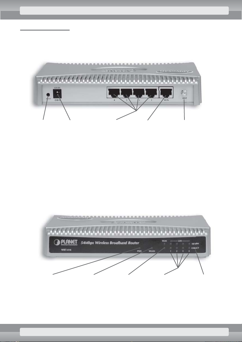
1.1 AP overview
Planet WAP-4035/WRT-414 Access Point is a modern device intended for 802.11b/g wireless
networks.
Its backplate contains:
•
RP-SMA port for external antenna, like the one enclosed with the device or any other
designed for 2,4 GHz WiFi networks.
•
Five Ethernet ports (10/100 Mbit/s) capable of automatic cable type detection (MDI or
MDIX).
•
Power socket (12 V DC) for power supply included with the device.
•
StatusReset button.
On the AP’s front panel:
•
PWR LED, indicating device status. When this LED is lit, the AP is ready to work. If this
LED is out, device configuration is being changed.
6. POWER 7. WLAN 10. Link/Act9. LAN1–48. WAN
1. RESET 2. Zasilanie 3. LAN1–4 4. WAN 5. RP-SMA Antena
INTRODUCTION 9
Page 11

•
Yellow WLAN LED’s indicating data transmission through wireless network.
•
LEDs designated with numbers 1 to 5 indicate mode of operation and data transmission
through corresponding Ethernet ports.
Depending on device configuration, its Ethernet ports can perform following functions:
•
Ports 1–5 work in switch mode and are visible as LAN1 or Bridge interface (in AP’s
management interface), and as eth0 interface (in Linux system).
•
Ports 2–5 operating in switch mode and are visible as LAN1 interface (in AP’s management
interface), and as eth0 interface (in Linux system). Port 1 works independently and is visible
as LAN2 or WAN interface (in AP’s management interface), and as eth1 interface (in Linux
system).
In router mode, the WAN interface is assigned to Ethernet 1 port,
and ports Ethernet 2 to 5 are used for LAN network.
1.2 Basic modes of operation
APPro54G software is available in several versions that differ in some features and are tailored to specific tasks. Users can pick any of these versions, and change them at any time. This way their APs can
always be adapted to any current needs. Steps needed to change installed version of APPro54G software are the same as in case of firmware upgrade, discussed in chapter 2.6 and Appendix C.
At this time, the following versions of APPro54G are available:
•
APPro54G standard: General-purpose version, intended for most users.
•
APPro54G turbo: Optimized version, that offers high transmission speeds (over 10 Mbit/s).
For more information about differences between particular flavors of APPro54G, visit the site
http://approsoftware. com/appro54g/
. This book refers to the standard version of the software. Devices equipped with APPro54G can operate in several basic modes, including Access Point, Router, Access Point Client, Bridge or part of WDS (Wireless Distribution System) . In each of these modes, the device performs different functions, suited for specific applications.
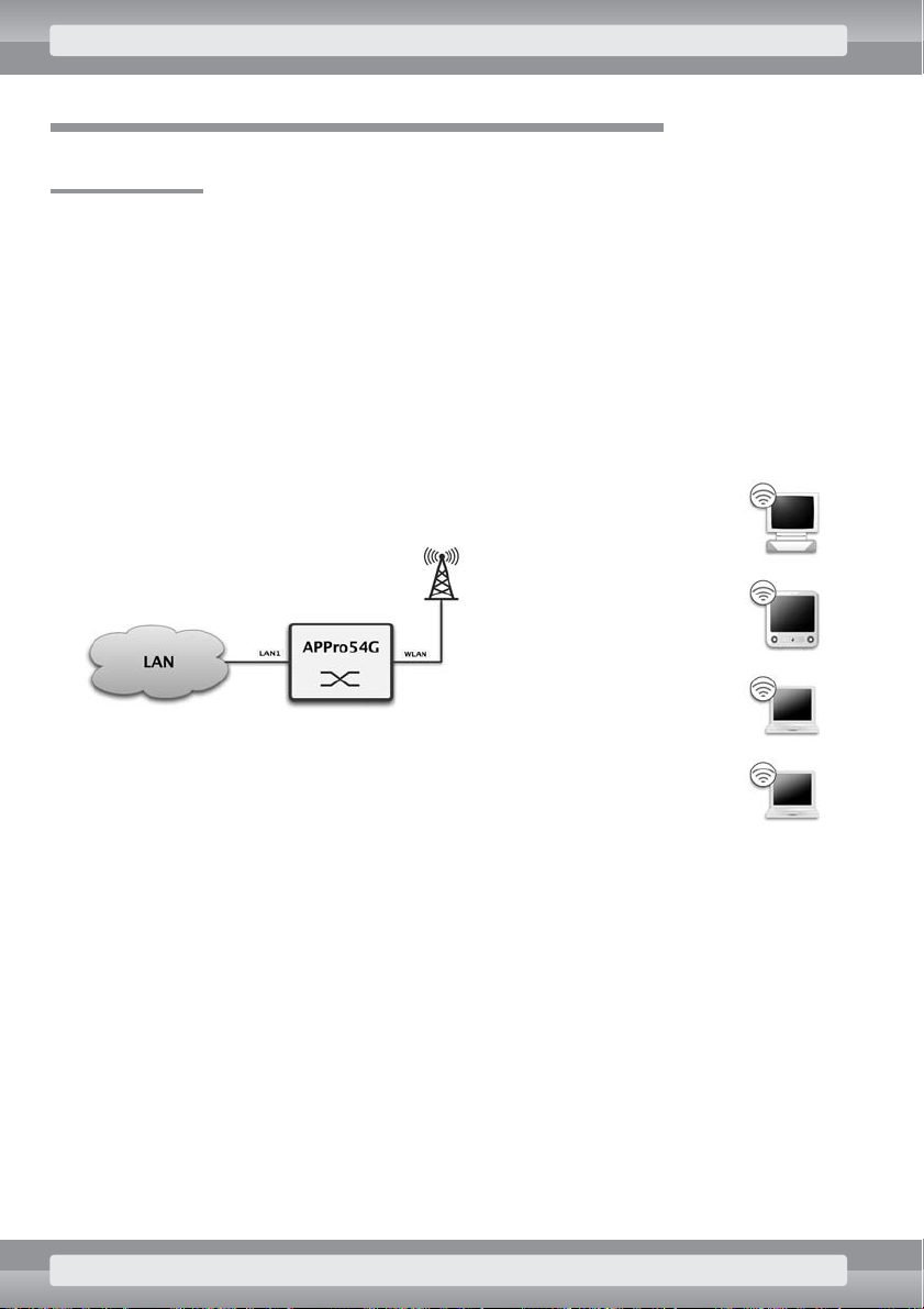
Access Point
In this mode, AP enables connection between WiFi devices and resources of wired LAN network.
AP’s LAN interfaces work as a multiport switch, relaying traffic between traditional LAN and wireless
WLAN networks. For more information: see page 16.
10 INTRODUCTION
Page 12

AP Client
In this mode AP operates as a WiFi network adapter, connected to the computer via an ordinary LAN
port. Simultaneously it’s possible to use AP as a multiport network switch that relays traffic between
LAN and WLAN networks, but to connect multiple LAN users to WiFi, adequate device configuration
is necessary. For more information: see page 22.
Bridge
Devices operating in bridge mode allow connection of several different LAN networks (up to five) with
wireless links. Such configuration offers slightly higher performance than common AP – APC connection. For more information: see page 28.
WISP (wireless connection sharing)
In this mode it’s possible to share a single wireless connection between multiple LAN users. Device
operates similarly to a client station (AP Client) , but additionally has routing feature enabled, and
it’s possible to use network address translation (NAT) . For more information: see page 41.
Wireless Router (WAN connection sharing)
This mode enables sharing with multiple users a connection (usually to the Internet) provided via the
Ethernet interface. The shared connection is available to both LAN and WiFi network users. For more
information: see page 47.
WDS/Repeater
Device operating in this mode acts as an element of Wireless Distribution System (WDS) . Such system enables creation of a wireless network that covers a much larger area than is possible with single
Access Point. For more information: see page 61.
APPro54G software has much greater capabilities, such as functions that optimize network operation, connection diagnostics, address filtering or bandwidth management for specific users. These topics
are covered in detail on (in the) next sections of this guide.
INTRODUCTION 11
Page 13

2 Device setup
2.1 Starting the AP device
After powering up, the device shortly flashes its PWR LED. Then the operating system is loaded, which
is indicated with PWR LED going out. When the LED is lit again, AP is ready to work and can be
accessed, for example via the Web browser.
2.2 Accessing the Web interface
Before AP can be used, it’s necessary to connect the device with a PC using enclosed LAN cable. The
computer needs to have a LAN adapter as well. Also, you can connect AP to your existing LAN (for
example to a switch) , and configure the device using any of networked computers. Ensure that the AP
is connected to the network via one of LAN2–LAN5 ports. Also, you need to properly configure network
settings of your computer. The following example shows how to configure a computer with Windows
XP OS.
Network settings for Windows XP
Default IP address of Access Point is
192.168.100.252
with subnet mask of
255.255.255.0
(additional information on default network settings is shown in box below) . In order to communicate with
the AP, your computer needs to have an IP address from the same class, e. g.
192.168.100.1
.
To configure your PC’s network settings for communication with AP
•
From
Start
menu choose
Control Panel
.
•
In Control Panel window click
Switch to Classic View
and double-click the
Network
Connections
. A list of network connections will be displayed.
•
Right-click on
Local Area Connection
corresponding to interface connected with AP, and
choose
Properties
. A dialog box with network settings will be shown.
•
Highlight
Internet Protocol (TCP/IP)
on the list and click
Properties
button.
Default settings of Access Point
IP Address
192.168.100.252
Subnet mask
255.255.255.0
Gateway
192.168.100.254
login
admin
password
admin
SSID
APPRO
Channel
7
DHCP Server
wy∏àczony
Mode
Access Point
12 DEVICE SETUP
Page 14

•
In the Internet Protocol (TCP/IP) Properties dialog enable
Use the following
IP address
option, and in
IP address
and
Subnet mask
fields type values
192.168.100.1
and
255.255.255.0
respectively. You can leave other fields unchanged.
•
Close dialogs, confirming new settings with OKbutton.
Your computer is now ready to work the with Access Point device. Now you can power up the AP, and
on computer launch a Web browser that supports JavaScript (some of popular browsers are Internet
Explorer, Mozilla and Opera) .
Opening device’s management panel
•
After proper setup of network connection and powering up the AP, you can open its manage-
ment panel. In order to do that, you need to open a Web browser, in address bar type
http: //192.168.100.252/
and then press the Enter key.
•
A dialog box is displayed, asking for username and password. If AP has default password
settings, in both fields type word
admin
.
In order to improve network security, you should change device’s default user-
name and password. This will prevent unauthorized users from changing
AP’s configuration.
•
APPro54G management page will be shown in browser window. If your copy of
APPro54G software is still unregistered, you’ll also see a dialog box asking for product regi-
stration. The registration requires only one piece of information: the e-mail address of the
APPro54G user.
Advanced users will appreciate the possibility of logging on directly to device’s Linux console via Telnet
or SSH protocols. To use this feature, all you need to do is to enter device’s IP as a host address. Username and password are the same as in AP’s Web interface.
Registered users will receive messages strictly concerning APPro54
software (i.e. about latest updates and new products from APPro family).
E-mail sent during registration won’t be shared with any third party, nor
used for any other purposes than stated above.
DEVICE SETUP 13
Page 15

2.3 Restoring AP’s default settings
In case of AP’s incorrect configuration (e.g. resulting in lack of access to Web interface), you can restore
device’s settings to factory defaults. To perform this operation, you need to wait until system loading
completes (PWR LED is on again), and then press and hold Reset button, placed on AP’s back panel.
After about three seconds PWR LED will go out – at this point you can release Reset button and you
must not press it at least until AP’s completely restarted and PWR LED is lit again. AP will be accessible
under its default IP address after device’s PWR LED is lit again.
To restore default settings using AP’s Web interface:
•
Log on to the AP (see: page 12) .
•
In
Other
section click on
Upgrade Firmware
.
•
Click
Restore Default
button.
•
Wait a few seconds until AP reverts to default settings.
Default settings will be written to device’s memory, but they won’t be
activated until you restart AP or click the Apply Changes button.
2.4 Changing the access password
After installing device you should change default username and password as quickly as possible. This
will prevent AP’s management interface from unauthorized access.
To change APPro54G’s access password:
•
Log on to the AP (see: page 12) .
•
In
Other
section click
Password Change
.
•
In
User Name
field type new username.
•
In both
New Password
and
Confirm Password
fields enter your new access password.
•
Save new settings by clicking OKbutton.
•
To restore page’s initial values, click
Reset
button.
2.5 Confirming and activating new settings
In APPro54G’s Web interface, each page that allows change of settings contains two buttons: OKand
Apply Changes
. Their purpose is always the same – OKbutton saves new parameters in device’s me-
mory, but activation of these settings will take place only when AP is restarted or after clicking
Apply
Changes
button. Pressing
Apply Changes
button also saves new settings, but at the same time it ac-
tivates them.
14 DEVICE SETUP
Page 16

2.6 Updating the firmware
With the Firmware Update feature users can perform AP modernization. Usually new versions of
APPro54G software include new functionality or improved utilization of AP’s hardware resources.
Upgrade operation is very simple: you just need to download a file with latest version of
APPro54G from the Internet, and then upload it to the device.
To upgrade APPro54G software in AP device:
•
Launch Web browser (e. g. Firefox, Opera or Internet Explorer) .
•
In addres bar, type the following address
http: //approsoftware.com/
.
•
In
Download
section, choose the latest version of APPro54G software.
•
In browser’s address bar type AP’s IP address (default is
http: //192.168.100.252/
) .
Enter username and password when asked (default:
admin
and
admin
) .
•
In
Other
section click on
Upgrade Firmware
. A panel will be displayed that allows softwa-
re upgrade.
•
In
Select File
box specify path and filename of downloaded firmware. You can also click
Choose
button and select a file from new dialog box.
•
Click on
Upload
button.
•
To restart device with the new firmware, in
Other
section click
Reboot
, and then click on
Reboot
button. The device will perform a complete system restart, and then it will run the
new version of APPro54G.
It is extremely important to ensure that the uploaded file contains correct
firmware and isn’t corrupted. If the downloaded file has some errors or is
intended for another type of device, AP will stop working. To restore AP’s
correct operation (in case of damaged software) or revert to manufacturer’s
original firmware, follow steps described on page 140.
APPro54G versions older than 01 Jun 2006 are not suitable
for Planet WAP-4035/WRT-414 Access Point.
DEVICE SETUP 15
Page 17
3. Step by step: common configurations
3.1 AP Mode
In this mode, you can use your AP to connect wireless devices to a standard wired LAN network. Access Point operates like a multiport network switch, that relays traffic between LAN and WLAN networks.
This section doesn’t apply to AP mode with NAT feature enabled. Such configurations are dis-
cussed on following pages.
Connection setup
LAN network can be connected to any Ethernet port in the AP (ports are marked with numbers 1 to
5). Additionally, these ports work as a standard network switch, which allows connection to extra
devices.
Requirements
•
To configure AP device, it has to operate with IP address and subnet mask consistent with
addressing scheme established by network administrator or service provider (see: page 12).
•
To provide AP with Internet access, you need to set up proper gateway and name server
(DNS) addresses in device’s options.
•
If AP’s configuration was previously altered, it’s recommended to restore its default settings.
16 STEP BY STEP: COMMON CONFIGURATIONS
Page 18
Actions
•
Log on to the AP (see: page 12).
•
On
Wireless/Site Survey
page find a free, or the least occupied WiFi channel
(see: page 99).
•
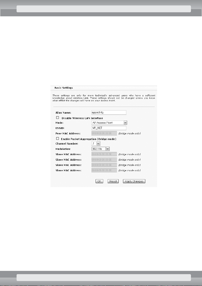
On
Wireless/Basic Settings
page set the following options:
r
Mode:
AP Access Point;
r
ESSID
: enter name of your network, e. g.:
MY_NET
;
r
Enable Packet Aggregation
: remove selection;
r
Channel Number
: choose number of channel found on
Site Survey
page;
r
Modulation
: choose
802.11b
;
r
Click on OKbutton.
STEP BY STEP: COMMON CONFIGURATIONS 17
Page 19
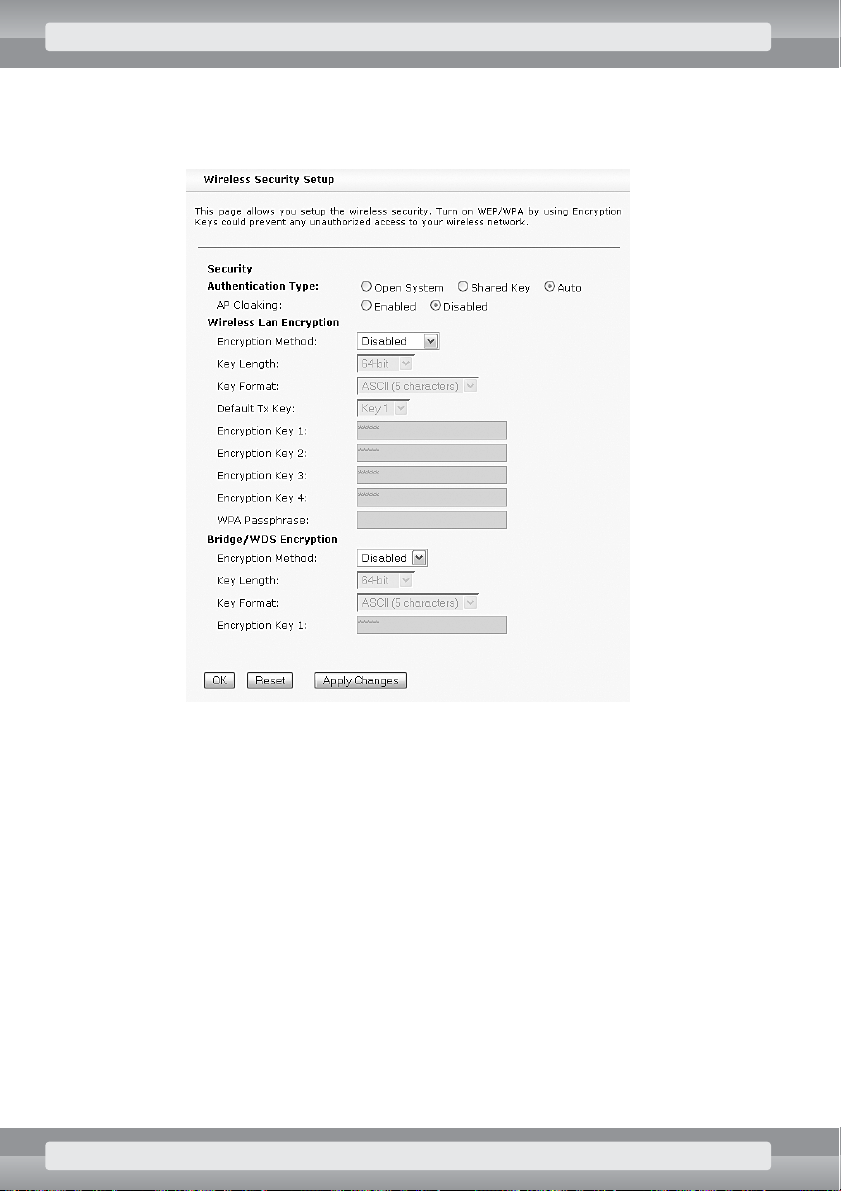
•
On
Wireless/Security
page set the following options:
r
Authentication Type
: Auto;
r
Click on OKbutton.
18 STEP BY STEP: COMMON CONFIGURATIONS
Page 20
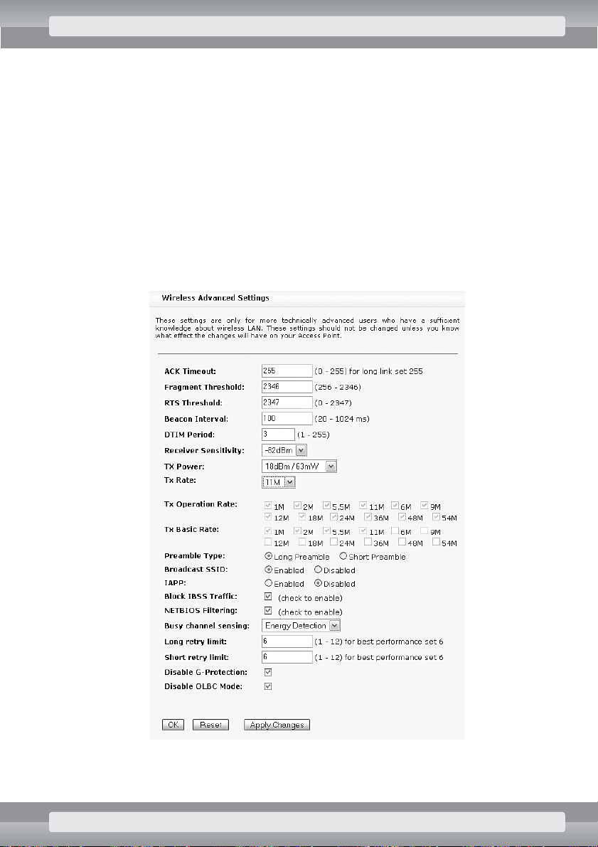
•
On
Wireless/Advanced Settings
page set the following options:
r
ACK Timeout
: 255;
r
Receiver Sensitivity
: -82 dBm;
r
TX Power
: 18 dBm;
r
Tx Rate
: 11M;
r
Block IBSS Traffic
: select this option to disable direct communication between
WiFi adapters;
r
NETBIOS Filtering
: select this option to disable „network neighborhood” – related com-
munication (like in Windows OS) between LAN and wireless networks;
r
Busy channel sensing
: Energy Detection;
r
Long retry limit
: 6;
r
Short retry limit
: 6;
r
Click on OKbutton.
STEP BY STEP: COMMON CONFIGURATIONS 19
Page 21
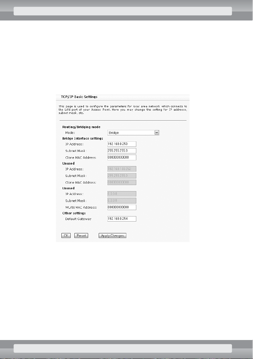
•
On
TCP/IP/Basic Settings
page set the following options:
r
Routing/Bridging mode
: Bridge;
r
Bridge Interface settings
– enter IP address and subnet mask of your
AP device.
–
IP Address
: IP address;
–
Subnet Mask
: subnet mask;
r
Other settings/Default Gateway
: if your AP operates in LAN network with Inter-
net access, enter address of the gateway (a device that relays Internet communication).
r
Click on OKbutton.
20 STEP BY STEP: COMMON CONFIGURATIONS
Page 22
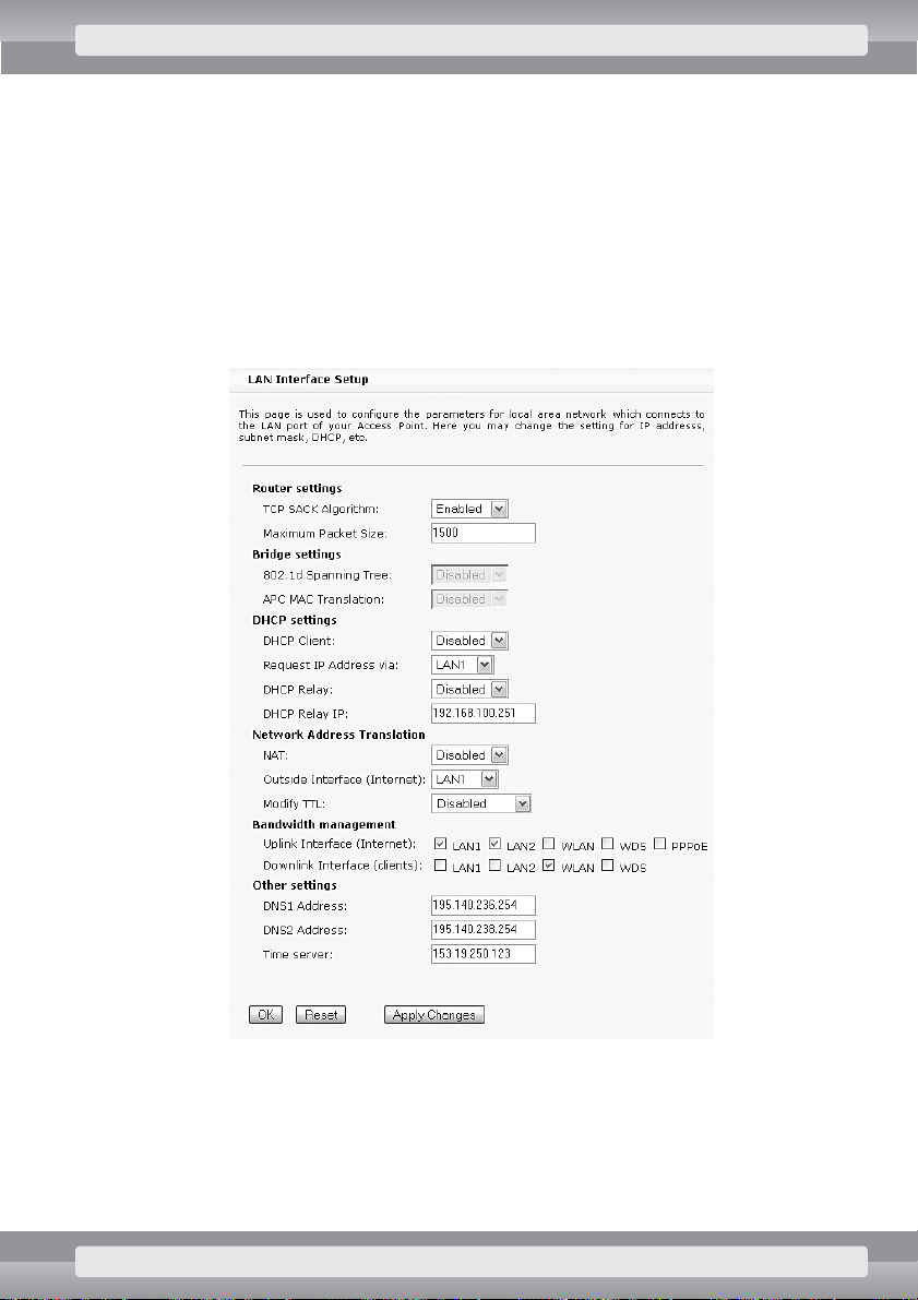
•
On
TCP/IP/Advanced Settings
page set the following options:
r
In
Network Address Translation
section:
–
NAT
: choose Disabled;
r
In
Bandwidth management
section:
–
Uplink Interface (Internet)
: choose
LAN1, LAN2
;
–
Downlink Interface (clients)
: choose
WLAN
;
r
In
Other settings
section:
–
DNS Address
: type IP address of the name server (DNS) , obtained from your Inter-
net provider.
•
Click on
Apply Changes
button
After setting these options, you need to configure each computer in the wireless network with appropriate settings. At this point the Internet connection should be already available. If network operates
properly with new settings, you can additionally configure:
•
encryption of data transmission (see: page 97),
•
authentication of client devices (see: page 94),
•
bandwidth management (see: page 72).
STEP BY STEP: COMMON CONFIGURATIONS 21
Page 23
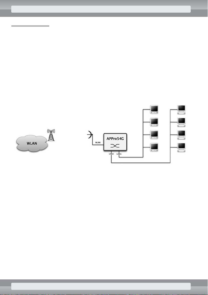
3.2 APC Mode
In APC mode (Access Point Client) device operates as WiFi network adapter. At the same time,
it serves as a multiport switch, that relays traffic between WLAN and LAN networks. Thanks to MAC
address masking, single Access Point in APC mode can be used to connect several other devices
– however, it’s necessary to properly set up AP’s (base station’s) wireless network options.
This section doesn’t apply to APC mode with NAT feature enabled. Such configurations are discussed on following pages.
Connection setup
LAN network can be connected to any Ethernet port in the AP (ports are marked with numbers 1 to
5). Additionally, these ports operate as a standard network switch, which allows connection to extra
devices.
Requirements
•
To enable AP’s connection with wireless network, you need to know that network’s SSID.
•
For proper operation of AP in client mode, you need to know channel number and mode
(b or g) of wireless network you’d like to connect to.
•
If your network uses encryption, you need to know WEP or WPA encryption keys as well.
•
To enable communication between computers in LAN and a wireless network, machines in
LAN need to have IP addresses and subnet mask consistent with addressing scheme
established for WiFi network by AP administrator.
•
To configure AP device, it has to operate with IP address and subnet mask consistent with
addressing scheme established by network administrator or service provider.
•
To provide AP with Internet access, you need to set up proper gateway and name server
(DNS) addresses in device’s options.
•
If AP’s configuration was previously altered, it’s recommended to restore its default settings.
22 STEP BY STEP: COMMON CONFIGURATIONS
Page 24
Actions
•
Log on to the AP (see: page 12).
•
On the
Wireless/Site Survey
page find the correct base station
(see: page 99). Ensure that this station’s signal has adequate strength (recommended value
is 35 or more).
•
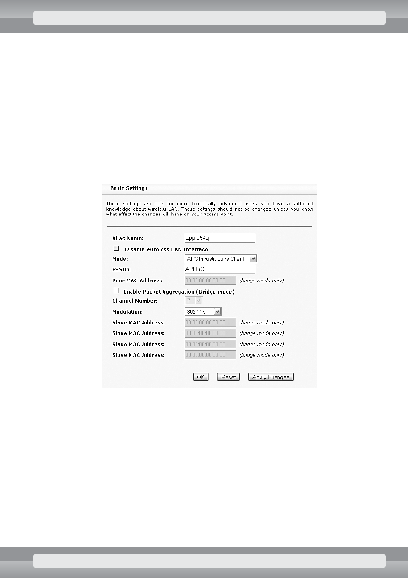
On
Wireless/Basic Settings
page set the following options:
r
Mode
: APC Infrastructure Client;
r
ESSID
: type SSID identifier of wireless network you want to connect to;
r
Enable Packet Aggregation
: remove selection;
r
Modulation
: choose operating mode of wireless network you want to connect to.
If you don’t know the correct value, select
802.11b
;
r
Click on OKbutton.
STEP BY STEP: COMMON CONFIGURATIONS 23
Page 25
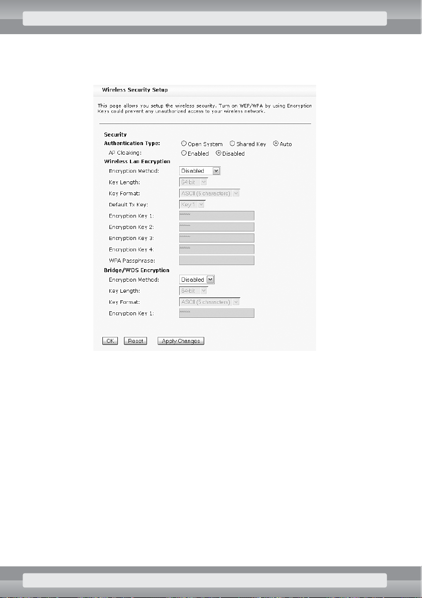
•
On
Wireless/Security
page set the following options:
r
Authentication Type
: Auto;
r
Click on OKbutton.
24 STEP BY STEP: COMMON CONFIGURATIONS
Page 26

•
On
Wireless/Advanced Settings
page set the following options:
r
ACK Timeout
: 255;
r
Receiver Sensitivity
: –82 dBm;
r
TX Power
: 18 dBm;
r
Tx Rate
: 11M;
r
Block IBSS Traffic
: select this option to disable direct communication between
WiFi adapters;
r
NETBIOS Filtering
: select this option to disable ‘network neighborhood’ – related
communication (like in Windows OS) between LAN and wireless networks;
r
Busy channel sensing
: Energy Detection;
r
Long retry limit
: 6;
r
Short retry limit
: 6;
r
Click on OKbutton.
STEP BY STEP: COMMON CONFIGURATIONS 25
Page 27
•
On
TCP/IP/Basic Settings
page set the following options:
r
Routing/Bridging mode
: Bridge;
r
Bridge Interface settings
– type correct (determined earlier) IP address
and subnet mask of your AP device;
–
IP Address
: IP address;
–
Subnet Mask
: subnet mask;
r
Other settings/Default Gateway
: if your AP operates in LAN network with Inter-
net access, enter address of the gateway (a device that relays Internet communication).
r
Click on OKbutton.
26 STEP BY STEP: COMMON CONFIGURATIONS
Page 28
•
On
TCP/IP/Advanced Settings
page set the following options:
r
In
Bridge settings
section:
–
APC MAC Translation
: choose Enabled;
r
In
Network Address Translation
section:
–
NAT
: choose Disabled;
r
In
Bandwidth management
section:
–
Uplink Interface (Internet)
: choose WLAN;
–
Downlink Interface (clients)
: choose LAN1, LAN2;
r
In
Other settings
section:
–
DNS Address
: type IP address of the name server (DNS), obtained from your
Internet provider.
•
Click on
Apply Changes
button.
STEP BY STEP: COMMON CONFIGURATIONS 27
Page 29
After setting these options, you need to configure each computer in the wireless network with appropriate settings. At this point the Internet connection should be already available. If network operates properly
with new settings, you can additionally configure:
•
access options for computers in LAN network and bandwidth management (see: page 72).
3.3 Bridge Master mode
In this mode, Access Point can connect together up to five separate LAN networks. It is possible only
after setting up Bridge Slave mode on other APs (max. four) that are connected to the Bridge Master –
each of slaves creates a wireless bridge with your AP. Such a bridge has slightly higher throughput than
typical connection between AP and its client (AP – APC). Additionally, AP in this mode doesn’t mask
MAC addresses.
Connection setup
LAN network can be connected to any Ethernet port in the AP (ports are marked with numbers 1 to
5). Additionally, these ports operate as a standard network switch, which allows connection to extra
devices.
28 STEP BY STEP: COMMON CONFIGURATIONS
Page 30

Requirements
•
In order to connect other APs configured as Bridge Slaves, it’s necessary to know their MAC
addresses.
Make sure that MAC addresses of Bridge Slaves are actually their WLAN inter-
face addresses (BSSID value on the AP Status page of APPro54G
Web interface).
•
To communicate with Bridge Master, Slave devices need to have IP addresses and subnet
masks consistent with addressing scheme established by network administrator or connection provider.
•
To properly configure Bridge Master device, you need to set AP’s IP address and subnet
mask that are consistent with addressing scheme established by network administrator
or service provider.
•
To provide AP with Internet access, you need to set up proper gateway and name server
(DNS) addresses in device’s options.
•
If AP’s configuration was previously altered, it’s recommended to restore its default settings.
STEP BY STEP: COMMON CONFIGURATIONS 29
Page 31

Actions
•
Log on to the AP (see: page 12).
•
On Wireless/Site Survey page find a free, or the least occupied WiFi channel, on which the
bridge will operate (see: page 99). All devices set up as bridge elements have to operate
on the same channel.
•
On
Wireless/Basic Settings
page set the following options:
r
Mode
: Bridge Master;
r
ESSID
: type name of your network, e.g.: MY_NET;
r
Enable Packet Aggregation
: remove selection;
r
Channel Number
: choose number of channel found on
Site Survey
page;
r
Modulation
: choose 802.11b;
r
Slave MAC Address
: type MAC addresses of Slave devices communicating with your
AP.
MAC addresses need to be entered in xx:xx:xx:xx:xx:xx format, where ’x’ stands for digits
0–9 and letters a–f (lowercase).
r
Click on OKbutton.
30 STEP BY STEP: COMMON CONFIGURATIONS
Page 32

•
On
Wireless/Security
page set the following options:
r
Authentication Type
: Auto;
r
Click on OKbutton.
STEP BY STEP: COMMON CONFIGURATIONS 31
Page 33

•
On
Wireless/Advanced Settings
page set the following options:
r
ACK Timeout
: 255;
r
Receiver Sensitivity
: –82 dBm;
r
TX Power
: 18 dBm;
r
Tx Rate
: 11M;
r
Block IBSS Traffic
: zselect this option to disable direct communication between
WiFi adapters;
r
NETBIOS Filtering
: select this option to disable ‘network neighborhood’ – related
communication (like in Windows OS) between LAN and wireless networks;
r
Busy channel sensing
: Energy Detection;
r
Long retry limit
: 6;
r
Short retry limit
: 6;
r
Click on OKbutton.
32 STEP BY STEP: COMMON CONFIGURATIONS
Page 34
•
On
TCP/IP/Basic Settings
page set the following options:
r
Routing/Bridging mode
: Bridge;
r
Bridge Interface settings
– type IP address and subnet mask of your AP device.
–
IP Address
: IP address;
–
Subnet Mask
: subnet mask;
r
Other settings/Default Gateway
: if your AP operates in LAN network with
Internet access, enter address of the gateway (a device that relays Internet
communication).
r
Click on OKbutton.
STEP BY STEP: COMMON CONFIGURATIONS 33
Page 35

•
On
TCP/IP/Advanced Settings
page set the following options:
r
In
Network Address Translation
section:
–
NAT
: choose Disabled;
r
In
Bandwidth management
section:
–
Uplink Interface (Internet)
: choose LAN1, LAN2;
–
Downlink Interface (clients)
: choose WDS (Bridge);
r
In
Other settings
section:
–
DNS Address
: type IP address of the name server (DNS), obtained from your
Internet provider.
•
Click on
Apply Changes
button.
34 STEP BY STEP: COMMON CONFIGURATIONS
Page 36

After setting these options, you need to configure other parts of the bridge – the devices operating as
Bridge Slaves. At this point it should be possible to communicate with other APs operating in Bridge
Slave mode.
If this initial set up is working properly, it is recommended to set up additional features:
•
bandwidth management (see: page 72),
•
encryption (see: page 84).
3.4 Bridge Slave mode
With Access Point operating in Bridge Slave, you can create a wireless bridge that consists of your AP
and other device configured as Bridge Master or Slave. Such a bridge has slightly higher throughput
than a typical connection between AP and its client (AP – APC). Additionally, it doesn’t mask MAC
addresses.
Connection setup
LAN network can be connected to any Ethernet port in the AP (ports are marked with numbers 1 to
5). Additionally, these ports operate as a standard network switch, which allows connection to extra
devices.
Requirements
•
To establish connection between your device and another AP that operates in Bridge Master
mode (or Slave in two-point bridges), it’s necessary to know MAC address of the other
device.
Make sure that MAC address of the other device is actually its WLAN interface
address (BSSID value on the AP Status page of APPro54G Web interface).
•
To properly configure Bridge Slave device, you need to set AP’s IP address and subnet mask
that are consistent with addressing scheme established by network administrator or service
provider (see: page 12).
•
To connect to the Internet, it’s recommended to enter Gateway and name server (DNS)
addresses.
•
If AP’s configuration was previously altered, it’s recommended to restore its default settings.
STEP BY STEP: COMMON CONFIGURATIONS 35
Page 37

Actions
•
Log on to the AP (see: page 12).
•
On
Wireless/Site Survey
page find a free, or the least occupied WiFi channel
(see: page 99).
Repeat these steps on each Slave and Master device of wireless bridge. All
APs configured as parts of your bridge have to operate on the same channel.
•
On
Wireless/Basic Settings
page set the following options:
r
Mode
: Bridge Slave;
r
ESSID
: type name of your network, e.g.: MY_NET;
r
Enable Packet Aggregation
: remove selection;
r
Channel Number
: choose channel number found on Site Survey page
(the same channel has to be set on other Master and Slave devices as well);
r
Modulation
: choose 802.11b;
r
Peer MAC Address
: type MAC address of bridge device (Master or Slave) that will
communicate with your AP. MAC address needs to be entered in xx:xx:xx:xx:xx:xx
format, where ‘x’ stands for digits 0–9 and letters a–f (lowercase).
r
Click on OKbutton.
36 STEP BY STEP: COMMON CONFIGURATIONS
Page 38

•
On
Wireless/Security
page set the following options:
r
Authentication Type
: Auto;
r
Click on OKbutton.
STEP BY STEP: COMMON CONFIGURATIONS 37
Page 39

•
On
Wireless/Advanced Settings
page set the following options:
r
ACK Timeout
: 255;
r
Receiver Sensitivity
: –82 dBm;
r
TX Power
: 18 dBm;
r
Tx Rate
: 11M;
r
Block IBSS Traffic
: select this option to disable direct communication between
WiFi adapters;
r
NETBIOS Filtering
: select this option to disable ‘network neighborhood’ – related
communication (like in Windows OS) between LAN and wireless networks;
r
Busy channel sensing
: Energy Detection;
r
Long retry limit
: 6;
r
Short retry limit
: 6;
r
Click on OKbutton.
38 STEP BY STEP: COMMON CONFIGURATIONS
Page 40

•
On
TCP/IP/Basic Settings
page set the following options:
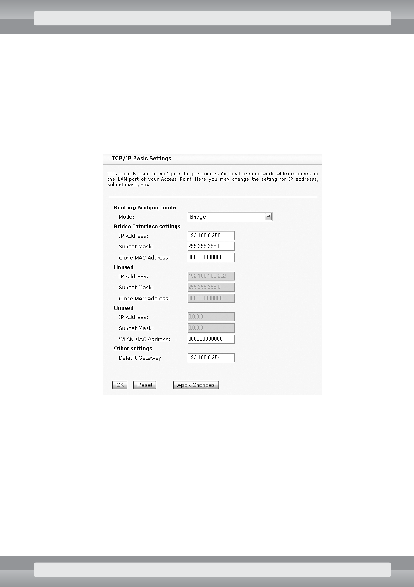
r
Routing/Bridging mode
: Bridge;
r
Bridge Interface settings
– type IP address and subnet mask of your AP device.
–
IP Address
: IP address;
–
Subnet Mask
: subnet mask;
r
Other settings/Default Gateway
: if your AP operates in LAN network with
Internet access, type address of the gateway (a device that relays Internet
communication).
r
Click on OKbutton.
STEP BY STEP: COMMON CONFIGURATIONS 39
Page 41

•
On
TCP/IP/Advanced Settings
page set the following options:
r
In
Network Address Translation
section:
–
NAT
: choose Disabled;
r
In
Bandwidth management
section:
–
Uplink Interface (Internet)
: choose WDS (Bridge);
–
Downlink Interface (clients)
: choose LAN1, LAN2;
r
In
Other settings
section:
–
DNS Address
: type IP address of the name server (DNS), obtained from your
Internet provider.
•
Click on
Apply Changes
button.
After setting these options, you need to configure device on other side of the bridge – operating either
as Bridge Slave or Master. At this point it should be possible to communicate with other AP operating
in Bridge mode.
If this initial set up is working properly, it is recommended to set up additional features:
•
bandwidth management (see: page 72).
40 STEP BY STEP: COMMON CONFIGURATIONS
Page 42

3.5 WISP mode (wireless connection sharing)
Thanks to WISP mode, you can share one wireless connection with many clients. In WISP mode, your
AP operates as a client APC station, but in addition it has enabled routing between wireless link and
LAN ports. Thanks to IP address translation (NAT) it’s also possible to connect several devices to one
AP, even if there’s only one IP address available on the wireless side.
Connection setup
LAN network can be connected to any Ethernet port in the AP (ports are marked with numbers 1 to
5). Additionally, these ports operate as a standard network switch, which allows connection to extra
devices.
Requirements
•
To enable AP’s connection with wireless network, you need to know that network’s SSID.
•
For proper operation of AP in client mode, you need to know a channel number and a mode
(b or g) of the wireless network you’d like to connect to.
•
If your network uses encryption, you need to know WEP or WPA encryption keys as well.
•
To enable communication between your AP and a WiFi network, you need to configure proper
IP address and subnet mask on AP’s wireless interface (obtained from connection provider).
•
To connect to the Internet, you need to know Gateway and name server (DNS) addresses.
•
If AP’s configuration was previously altered, it’s recommended to restore its default settings.
Example of addressing scheme for computers in LAN network
•
IP address range: 172.20.1.2 – 172.20.1.254
•
IP address of Access Point: 172.20.1.1
•
Subnet mask: 255.255.255.0
STEP BY STEP: COMMON CONFIGURATIONS 41
Page 43

Actions
•
Log on to the AP (see: page 12).
•
On
Wireless/Site Survey
page find a free, or the least occupied WiFi channel
(see: page 99). Also ensure that available signal has adequate strength (recommended value
is 35 or more).
•
On
Wireless/Basic Settings
page set the following options:
r
Mode
: APC Infrastructure Client;
r
ESSID
: type SSID identifier of wireless network you want to connect to;
r
Enable Packet Aggregation
: remove selection;
r
Channel Number
: choose number of channel found on
Site Survey
page;
r
Modulation
: choose operating mode of wireless network you want to connect to. If
you don’t know the correct value, select 802.11b;
r
Click on OKbutton.
42 STEP BY STEP: COMMON CONFIGURATIONS
Page 44

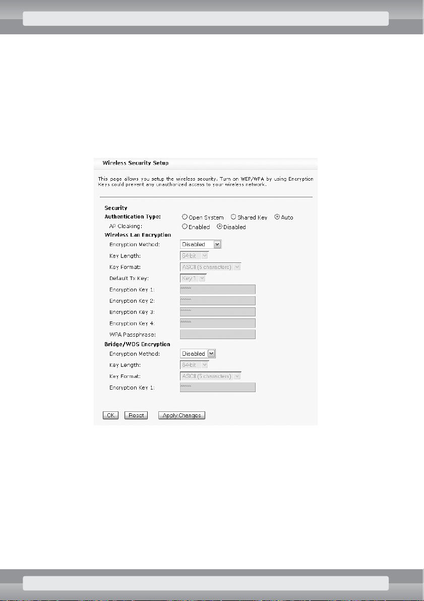
•
On
Wireless/Security
page set the following options:
r
Authentication Type
: Auto;
r
Click on OKbutton.
STEP BY STEP: COMMON CONFIGURATIONS 43
Page 45

•
On
Wireless/Advanced Settings
page set the following options:
r
ACK Timeout
: 255;
r
Receiver Sensitivity
: –82 dBm;
r
TX Power
: 18 dBm;
r
Tx Rate
: 11M;
r
Block IBSS Traffic
: zaznacz t´ opcj´, aby uniemo˝liwiç komunikacj´ mi´dzy karta-
mi radiowymi;
r
NETBIOS Filtering
: select this option to disable direct communication between
WiFi adapters;
r
Busy channel sensing
: Energy Detection;
r
Long retry limit
: 6;
r
Short retry limit
: 6;
r
Click on OKbutton.
44 STEP BY STEP: COMMON CONFIGURATIONS
Page 46

•
On
TCP/IP/Basic Settings
page set the following options:
r
Routing/Bridging mode
: Router (LAN1/LAN2 Bridged);
r
LAN1/LAN2 Bridged interface settings
– type IP address and subnet mask
of your AP device.
–
IP Address
: 172.20.1.1;
–
Subnet Mask
: 255.255.255.0;
r
WLAN Interface settings
– enter settings obtained from connection provider.
–
IP Address
: IP address obtained from connection provider;
–
Subnet Mask
: subnet mask obtained from connection provider;
r
Other settings/Default Gateway
: address of the gateway (a computer relaying
communication with Internet), obtained from wireless connection provider.
r
Click on OKbutton.
STEP BY STEP: COMMON CONFIGURATIONS 45
Page 47

•
On
TCP/IP/Advanced Settings
page set the following options:
r
In
Bridge settings
section:
–
APC MAC Translation
: choose Enabled;
r
In
Network Address Translation
section:
–
NAT
: choose Enabled;
–
Outside Interface (Internet)
: choose WLAN;
r
In
Bandwidth management
section:
–
Uplink Interface (Internet)
: choose WLAN;
–
Downlink Interface (clients)
: choose LAN1, LAN2;
r
In
Other settings
section:
–
DNS Address
: type IP address of the name server (DNS), obtained from your
Internet provider.
•
Click on
Apply Changes
button.
46 STEP BY STEP: COMMON CONFIGURATIONS
Page 48

After setting these options, you need to configure computers in LAN network, by using following
settings:
•
IP Address: unique address from range of 172.20.1.2 – 172.20.1.254;
•
Subnet mask: 255.255.255.0;
•
Gateway Address: 172.20.1.1;
•
DNS Server: obtained from wireless connection provider or one of openly available servers,
e.g.: 194.204.159.1.
At this point it should be possible to communicate with the Internet. If this initial set up is working
properly, it is recommended to set up additional features:
•
authentication of client devices (see: page 97),
•
bandwidth management (see: page 72),
•
DHCP Server. (see: page 107).
3.6 Wireless Router mode (WAN connection sharing)
The following section refers to APPro54G’s configuration used for sharing of WAN connection (usually:
to the Internet) provided via Ethernet interface. These settings include NAT functionality and access to
external network for devices operating in both LAN and Wireless networks.
Requirements:
•
Internet cable should be connected to AP’s Ethernet 1 port.
•
Internal LAN network should be connected to any of AP’s Ethernet 2–5 ports.
•
To enable communication between AP and the Internet (via the WAN interface), you need
to set proper IP address and subnet mask (obtained from connection provider).
•
To connect with the Internet, you need to know Gateway and name server (DNS) addresses.
•
If AP’s configuration was previously altered, it’s recommended to restore its default settings.
STEP BY STEP: COMMON CONFIGURATIONS 47
Page 49

Actions
•
Log on to the AP (see: page 12).
•
On Wireless/Site Survey page find a free, or the least occupied WiFi channel
(see: page 99).
•
On
Wireless/Basic Settings
page set following options:
r
Mode
: AP Access Point;
r
ESSID
: type wireless network identifier (SSID), e.g. MY_NET;
r
Enable Packet Aggregation
: remove selection;
r
Channel Number
: choose number of channel found on
Site Survey
page;
r
Modulation
: choose 802.11b;
r
Click on OKbutton.
Example of addressing scheme for computers in LAN network
•
IP address range: 172.20.1.2 – 172.20.1.254
•
IP address of Access Point: 172.20.1.1
•
Subnet mask: 255.255.255.0
48 STEP BY STEP: COMMON CONFIGURATIONS
Page 50

•
On
Wireless/Security
page set the following options:
r
Authentication Type
: Auto;
r
Click on OKbutton.
STEP BY STEP: COMMON CONFIGURATIONS 49
Page 51

•
On
Wireless/Advanced Settings
page set the following options:
r
ACK Timeout
: 255;
r
Receiver Sensitivity
: –82 dBm;
r
TX Power
: 18 dBm;
r
Tx Rate
: 11M;
r
Block IBSS Traffic
: select this option to disable direct communication between
WiFi adapters;
r
NETBIOS Filtering
: select this option to disable ‘network neighborhood’ – related
communication (like in Windows OS) between LAN and wireless networks;
r
Busy channel sensing
: Energy Detection;
r
Long retry limit
: 6;
r
Short retry limit
: 6;
r
Click on OKbutton.
50 STEP BY STEP: COMMON CONFIGURATIONS
Page 52

•
On
TCP/IP/Basic Settings
page set the following options:
r
Routing/Bridging mode
: Router (WLAN, LAN1 Bridged);
r
LAN1/WLAN Bridged interface settings
– type IP address and subnet mask
of your AP device.
–
IP Address
: 172.20.1.1;
–
Subnet Mask
: 255.255.255.0;
r
WAN Interface settings (LAN2)
– enter settings obtained from connection
provider.
–
IP Address
: IP address obtained from connection provider;
–
Subnet Mask
: subnet mask obtained from connection provider;
r
Other settings/Default Gateway
: address of the gateway (a computer relaying
communication with Internet), obtained from wireless connection provider.
r
Click on OKbutton.
STEP BY STEP: COMMON CONFIGURATIONS 51
Page 53

•
On
TCP/IP/Advanced Settings
page set the following options:
r
In
Bridge settings
section:
–
APC MAC Translation
: choose Enabled;
r
In
Network Address Translation
section:
–
NAT
: choose Enabled;
–
Outside Interface (Internet)
: choose LAN2.
r
In
Bandwidth management
section:
–
Uplink Interface (Internet)
: choose LAN2;
–
Downlink Interface (clients)
: choose WLAN, LAN1.
r
In
Other settings
section:
–
DNS Address
: type IP address of the name server (DNS), obtained from your
Internet provider.
•
Click on
Apply Changes
button.
52 STEP BY STEP: COMMON CONFIGURATIONS
Page 54

After setting these options, you need to configure computers in LAN network with the following settings:
•
IP Address: unique address from range of 172.20.1.2 – 172.20.1.254;
•
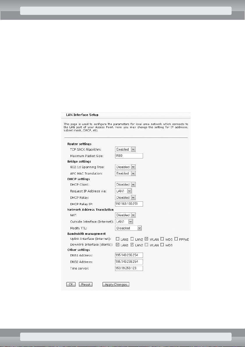
Subnet mask: 255.255.255.0;
•
Gateway Address: 172.20.1.1;
•
SDNS Server: obtained from wireless connection provider or one of openly available servers,
e.g.: 194.204.159.1.
At this point it should be possible to communicate with the Internet. If this initial set up is working
properly, it is recommended to set up additional features:
•
encryption of data transmission (see: page 97),
•
authentication of client devices (see: page 97),
•
bandwidth management (see: page 72),
•
DHCP Server (see: page 107).
3.7 Wireless Router mode (DSL connection sharing)
The following section refers to APPro54G’s configuration used for sharing Internet connection (provided
via the DSL modem with Ethernet port). Unfortunately for users of modems equipped with USB ports
only, they will have to replace these devices. This section is not intended for users of services based
on PPPoE protocol.
Requirements
•
Working Internet connection and complete information (obtained from service provider),
needed to configure your device (IP address with subnet mask, Gateway, and DNS).
•
Your DSL modem should be connected to Ethernet 1 port in the AP. In AP device this port
can operate as WAN interface. Computers in local network can be connected to AP’s
Ethernet 2–5.
From now on, AP’s configuration procedure is identical to WAN connection sharing (page 47).
STEP BY STEP: COMMON CONFIGURATIONS 53
Page 55

3.8 Wireless Router mode (DSL with PPPoE connection sharing)
The following section refers to APPro54G’s configuration for sharing of DSL connection that uses PPPoE
authentication. In this case, you need an ADSL modem with Ethernet port, but without router functionality.
If your modem is equipped with USB port only, it’s necessary to replace it with an Ethernet model. These
settings include NAT functionality and access to the Internet for devices operating both in LAN and
wireless networks.
Requirements
•
Internet cable from ADSL modem should be connected to AP’s Ethernet 1 port.
•
Internal LAN network should be connected to any of AP’s Ethernet 2–5 ports.
•
For proper operation of Internet connection, it’s necessary to know IP, DNS and Gateway
addresses, as well as subnet mask – this informations should be obtained from your service
provider.
•
If AP’s configuration was previously altered, it’s recommended to restore its default settings.
54 STEP BY STEP: COMMON CONFIGURATIONS
Page 56

Actions
•
Log on to the AP (see: page 12).
•
On Wireless/Site Survey page find a free, or the least occupied WiFi channel
(see: page 99).
•
On
Wireless/Basic Settings
page set the following options:
r
Mode
: AP Access Point;
r
ESSID
: type wireless network identifier (SSID), e.g. MY_NET;
r
Enable Packet Aggregation
: remove selection;
r
Channel Number
: choose number of channel found on
Site Survey
page;
r
Modulation
: choose 802.11b;
r
Click on OKbutton.
Example of addressing scheme for computers in local network:
•
IP address range: 172.20.1.2 – 172.20.1.254
•
IP address of Access Point: 172.20.1.1
•
Subnet mask: 255.255.255.0
STEP BY STEP: COMMON CONFIGURATIONS 55
Page 57

•
On
Wireless/Security
page set the following options:
r
Authentication Type
: Auto;
r
Click on OKbutton.
56 STEP BY STEP: COMMON CONFIGURATIONS
Page 58

•
On
Wireless/Advanced Settings
page set the following options:
r
ACK Timeout
: 255;
r
Receiver Sensitivity
: –82 dBm;
r
TX Power
: 18 dBm;
r
Tx Rate
: 11M;
r
Block IBSS Traffic
: select this option to disable direct communication between
WiFi adapters;
r
NETBIOS Filtering
: select this option to disable ‘network neighborhood’ – related
communication (like in Windows OS) between LAN and wireless networks;
r
Busy channel sensing
: Energy Detection;
r
Long retry limit
: 6;
r
Short retry limit
: 6;
r
Click on OKbutton.
STEP BY STEP: COMMON CONFIGURATIONS 57
Page 59

•
On
TCP/IP/Basic Settings
page set the following options:
r
Routing/Bridging mode
: Router (WLAN, LAN1 Bridged);
r
LAN1/WLAN Bridged interface settings
– type IP address and subnet mask of
your AP device.
–
IP Address
: 172.20.1.1;
–
Subnet Mask
: 255.255.255.0;
r
WAN Interface settings (LAN2)
– tenter settings obtained from connection
provider.
–
IP Address
: IP address obtained from your service provider, or 0.0.0.0
(this value will be automatically replaced with the correct one);
–
Subnet Mask
: subnet mask obtained from your service provider, or 255.255.255.0
(this value will be automatically replaced with the correct one);
r
Other settings/Default Gateway
: address of the Gateway (a computer relaying
Internet traffic) obtained from your service provider, or 0.0.0.0 (this value will be
automatically replaced with the correct one);
r
Click on OKbutton.
58 STEP BY STEP: COMMON CONFIGURATIONS
Page 60

•
On
TCP/IP/Advanced Settings
page set the following options:
r
In
Network Address Translation
section:
–
NAT
: choose Enabled;
–
Outside Interface (Internet)
: choose PPPoE.
r
In
Bandwidth management
section:
–
Uplink Interface (Internet)
: choose PPPoE;
–
Downlink Interface (clients)
: choose WLAN, LAN1.
r
In
Other settings
section:
–
DNS Address
: type IP address of a name server (DNS) provided by your service
provider.
r
Click on OKbutton.
STEP BY STEP: COMMON CONFIGURATIONS 59
Page 61

•
On
TCP/IP/PPPoE Settings
page set the following options:
r
PPPoE Relay Settings
: choose Disabled;
r
PPPoE Client Settings
: choose Enabled;
r
Interface
: choose LAN2;
r
PPPoE User Name
: type login (user name) for your Internet service;
r
PPPoE Password
: type password for your Internet service.
•
Click on
Apply Changes
button.
After setting these options, you need to configure computers in LAN and WLAN networks with the
following settings:
•
IP Address: unique address from range of 172.20.1.2 – 172.20.1.254;
•
Subnet mask: 255.255.255.0;
•
Gateway Address: 172.20.1.1;
•
DNS Server: obtained from wireless connection provider or one of openly available servers, e.g.:
194.204.159.1.
At this point it should be possible to communicate with the Internet. If this initial setup is working
properly, it is recommended to set up additional features:
•
encryption of data transmission (see: page 97),
•
authentication of client devices (see: page 97),
•
bandwidth management (see: page 72),
•
DHCP Server (see: page 107).
60 STEP BY STEP: COMMON CONFIGURATIONS
Page 62

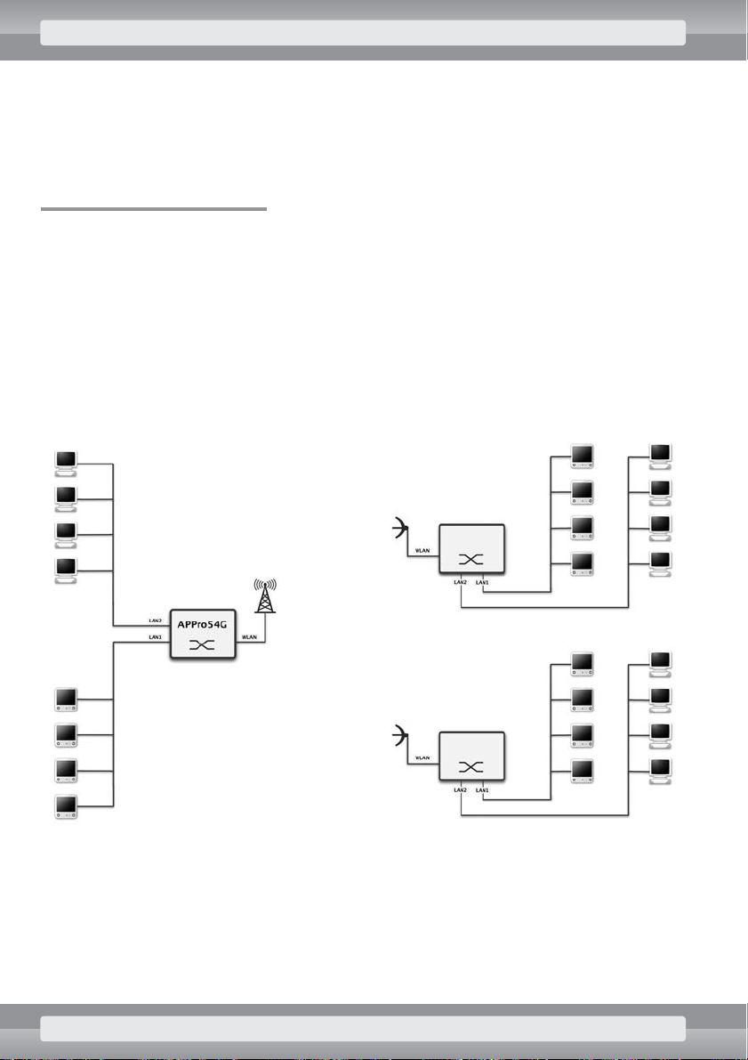
3.9 WDS/Repeater mode
AP devices operating in WDS mode (Wireless Distribution System) can extend the range of a single
wireless network to much larger areas. Each of WDS base stations can establish multiple connections
with client stations (e.g. computers equipped with WiFi adapters), and – at the same time –
communicate with up to six other base stations (in wireless bridge mode). Each of the base stations
have to operate on the same channel and in the same mode (802.11b or 802.11g). With such stations
it’s possible to get longer range of a WiFi network without using Ethernet cables to connect APs.
WDS mode degrades overall performance of a wireless network. This is
a result of necessity to distribute data over whole network, which doubles
bandwidth requirements with each additional base station in WDS (each data
packet is send to repeater stations first, and only after that to its destination).
Primary and secondary base stations
In typical WDS configurations there’s one primary base station connected to several secondary stations.
Actions
•
Configure primary and secondary base stations for AP mode (see: page 16). Each device
has to operate on the same WiFi channel and with the same settings of transmission speed
and mode, but they can use different ESSID identifiers.
•
Log on to primary base station (see: page 12).
STEP BY STEP: COMMON CONFIGURATIONS 61
Page 63

•
On
Wireless/WDS Settings
page set the following options:
r
Enable WDS
: select this option;
r
MAC Address/Comment
: type MAC addresses and descriptions for each secondary
WDS station. MMAC address needs to be entered in xx:xx:xx:xx:xx:xx format, where
‘x’ stands for digits 0–9 and letters a–f (lowercase). Add parameters of secondary
WDS station, by clicking on
OK
button. The list of secondary stations holds up to six
items;
Make sure you specified MAC address of a wireless interface. You can find it in
BSSID value on AP Status page of APPro54G Web interface.
r
Click on OKbutton.
62 STEP BY STEP: COMMON CONFIGURATIONS
Page 64

•
On
TCP/IP/Advanced Settings
page set the following options:
r
In
Bandwidth management
section:
–
Uplink Interface (Internet)
: choose LAN1, LAN2;
–
Downlink Interface
(clients): choose WLAN, WDS;
r
In
Other settings
section:
–
DNS Address
: type IP address of a name server (DNS) provided by your service
provider.
•
Click on
Apply Changes
button.
STEP BY STEP: COMMON CONFIGURATIONS 63
Page 65

•
Log on to each secondary WDS base station (see: page 12).
•
On
Wireless/WDS Settings
page set the following options:
r
Enable WDS
: select this option;
r
MAC Address/Comment
: enter MAC address and description of primary WDS station.
MAC address needs to be entered in xx:xx:xx:xx:xx:xx format, where ‘x’ stands for
digits 0–9 and letters a–f (lowercase). Add parameters of primary WDS station by
clicking on
OK
button.
Make sure you specified MAC address of a wireless interface. You can find it in
BSSID value on AP Status page of APPro54G Web interface.
r
Click on OKbutton.
64 STEP BY STEP: COMMON CONFIGURATIONS
Page 66

•
On
TCP/IP/Advanced Settings
page set the following options:
r
In
Bandwidth management
section:
–
Uplink Interface (Internet)
: choose WDS;
–
Downlink Interface (clients)
: choose WLAN, LAN1, LAN2;
•
Click on
Apply Changes
button.
STEP BY STEP: COMMON CONFIGURATIONS 65
Page 67

Chain of connected base stations
Another common WDS configuration is a chain of connected base stations.
Actions
•
Configure base stations of your WDS chain for AP mode (see: page 16). Each device has to
operate on the same WiFi channel and with the same settings of transmission speed and
mode, but they can use different ESSID identifiers.
•
Log on to first base station (see: page 12).
•
On
Wireless/WDS Settings
page set the following options:
r
Enable WDS
: select this option;
r
MAC Address/Comment
: Enter MAC address and description of second station in WDS
chain. MAC address needs to be entered in xx:xx:xx:xx:xx:xx format, where ‘x’ stands
for digits 0–9 and letters a–f (lowercase). Add parameters of secondary WDS station,
by clicking on OK button. Make sure you specified MAC address of a wireless
interface. You can find it in BSSID value on AP Status page of APPro54G Web
interface.
r
Click on OKbutton.
66 STEP BY STEP: COMMON CONFIGURATIONS
Page 68

•
On
TCP/IP/Advanced Settings
page set the following options:
r
In
Bandwidth management
section:
–
Uplink Interface (Internet)
: choose LAN1, LAN2;
–
Downlink Interface (clients)
: choose WLAN, WDS;
•
Click on
Apply Changes
button.
STEP BY STEP: COMMON CONFIGURATIONS 67
Page 69

•
Log on to second base station (see: page 12).
•
On
Wireless/WDS Settings
page set the following options:
r
Enable WDS
: select this option;
r
MAC Address/Comment
: enter MAC addresses and descriptions of first and third
station in WDS chain. MAC address needs to be entered in xx:xx:xx:xx:xx:xx format,
where ‘x’ stands for digits 0–9 and letters a–f (lowercase). Add parameters of WDS
stations by clicking on
OK
button.
Make sure you specified MAC address of a wireless interface. You can find it in
BSSID value on AP Status page of APPro54G Web interface.
r
Click on OKbutton.
68 STEP BY STEP: COMMON CONFIGURATIONS
Page 70

•
On
TCP/IP/Advanced Settings
page set the following options:
r
In
Bandwidth management
section:
–
Uplink Interface (Internet)
: choose WDS;
–
Downlink Interface (clients)
: choose WLAN, LAN1, LAN2;
•
Click on
Apply Changes
button.
STEP BY STEP: COMMON CONFIGURATIONS 69
Page 71

•
Log on to third (in this case – last) base station of WDS chain (see: page 12).
•
On
Wireless/WDS Settings
page set the following options:
r
Enable WDS
: select this option;
r
MAC Address/Comment
: enter MAC address and description of second (previous)
station in WDS chain. MAC address needs to be entered in xx:xx:xx:xx:xx:xx format,
where ‘x’ stands for digits 0–9 and letters a–f (lowercase). Add parameters of WDS
stations by clicking on
OK
button.
Make sure you specified MAC address of a wireless interface. You can find it in
BSSID value on AP Status page of APPro54G Web interface.
r
Click on OKbutton.
70 STEP BY STEP: COMMON CONFIGURATIONS
Page 72

•
On
TCP/IP/Advanced Settings
page set the following options:
r
In
Bandwidth management
section:
–
Uplink Interface (Internet)
: choose WDS;
– Downlink Interface (clients): choose WLAN, LAN1, LAN2;
•
Click on
Apply Changes
button.
In WDS mode the routing options are not available for traffic transmitted over WDS.
However, you can route traffic and enable NAT for Ethernet (LAN) interfaces.
STEP BY STEP: COMMON CONFIGURATIONS 71
Page 73

3.10 Bandwidth management
APPro54G software employs three independent methods of bandwidth management: QoS lets you
assign a bandwidth to each service type, Flow Limits regulates connection load, and the Traffic
Manager limits bandwidth for selected clients. These features are available in each working mode (AP,
APC), and regardless of router or bridge operation.
3.10.1 Selecting uplink and downlink interfaces
To ensure proper operation of QoS and Traffic Manager, it’s necessary to have correct settings of
Uplink
Interface (Internet)
and
Downlink Interface (clients)
parameters on
Advanced
Settings
page.
•
Uplink Interface
is the interface used for communication with the Internet, WAN
connection or a base station. Uplink Interface can be configured on any of LAN1, LAN2 or
WLAN interfaces, as well as on WDS or PPPoE connection.
•
Downlink Interface
refers to interfaces connected to AP’s clients (both in LAN and
wireless networks). Available settings are: LAN1 (physical ports Ethernet 2–5), LAN2
(physical port Ethernet 1), WLAN interface, and WDS link.
72 STEP BY STEP: COMMON CONFIGURATIONS
Page 74

You must not choose the same port to be both the uplink and downlink interface.
To ensure correct operation of QoS and Traffic Manager features, configure your AP in one of the modes
described in sections 3.1–3.9. Next, you need to configure
Uplink
and
Downlink
interfaces on
TCP/IP Advanced Settings
page (Bandwidth management section), based on the following
description:
•
AP mode:
r
Uplink
interface – select LAN1 or LAN2,
r
Downlink
interface – select WLAN.
To enable bandwidth management in WDS mode, you need to select the
WDS
option as well.
•
APC mode:
r
Uplink
interface – select WLAN.
r
Downlink
interface – select LAN1 and LAN2.
•
Bridge Master mode:
r
Uplink
interface – select LAN1 and LAN2,
r
Downlink
interface – select WDS.
•
Bridge Slave mode:
r
Uplink
interface – select WDS.
r
Downlink
interface – select LAN1 and LAN2.
•
WISP mode (wireless connection sharing):
r
Uplink
interface – select WLAN,
r
Downlink
interface – select LAN1 and LAN2.
•
WISP PPPoE mode (wireless connection sharing):
r
Uplink
interface – select PPPoE,
r
Downlink
interface – select LAN1 and LAN2.
•
Wireless Router mode (WAN/DSL connection sharing):
r
Uplink
interface – select LAN2,
r
Downlink
interface – select LAN1 and WLAN.
Uplink parameter, also referred to as upload or transmission rate of data sent
to external network (e.g. the Internet) is maximum speed, at which you can,
for example, send an e-mail. Controlling this kind of traffic is based on
limiting the transmission speed of packets sent through the interface selected
as Uplink.
Downlink parameter, also referred to as download, is maximum speed, at
which you can receive data from an external network. So, this is the speed,
at which you can, for example, get your e-mails. Controlling this traffic is
based on limiting the transmission speed of packets sent through any of the
interfaces selected as Downlink.
STEP BY STEP: COMMON CONFIGURATIONS 73
Page 75

•
Wireless Router mode (WAN/DSL with PPPoE connection sharing):
r
Uplink
interface – select PPPoE,
r
Downlink
interface – select LAN1 and WLAN.
WDS/Repeater mode (with WDS network in star configuration)
•
On the primary base station set the following options:
r
Uplink
interface – select LAN1 or LAN2,
r
Downlink
interface – select WDS,
r
If the primary base station has its own clients as well, you also need to select WLAN in
the
Downlink
interface options.
•
On each of the secondary base stations set the following options:
r
Uplink
interface – select WDS;
r
Downlink
interface – select WLAN;
r
If a secondary base station has its own clients connected to its Ethernet ports, you also
need to select LAN1 and LAN2 in the
Downlink
interface options.
WDS/Repeater mode (with WDS network in line configuration)
74 STEP BY STEP: COMMON CONFIGURATIONS
Page 76

If your WDS network is connected in line configuration, it’s optimal to set up bandwidth management
options on line’s first device – the one that connects a LAN network with the rest of WDS. It’s not
possible to manage the bandwidth on intermediate base stations of a WDS line.
•
Uplink
interface – select LAN1 or LAN2,
•
Downlink
interface – select WDS.
•
PPPoE
client mode
(Mikrotik)
:
r
Uplink
interface – select PPPoE,
r
Downlink
interface – select LAN1 and LAN2.
When configuring
Uplink
and
Downlink
interfaces, keep in mind the following guidelines:
•
The same interface should not be assigned both to
Uplink
and
Downlink
traffic at the
same time.
•
Bandwidth management is available only for traffic going out of any given interface
(
Downlink
traffic), because only in that case is packet queuing possible. In Linux system,
queuing for
Uplink
traffic actually applies to packets leaving the interface on the opposite
side of the data transmission path.
•
To have your traffic properly managed by APPro54G, you need to configure it in such a way,
that the data transmission to a client has to leave the
Downlink
interface, and the
transmission from a client leaves the
Uplink
interface.
•
This is the same reason why it’s not possible to manage traffic simultaneously between
devices on your local network (connected to LAN1 and LAN2 interfaces) and between your
network and the Internet (traffic leaving the WLAN port). If you configured WLAN interface
as
Uplink
, and your LAN1/LAN2 as a
Downlink
(these settings are required for the
management of Internet traffic), transmissions between LAN1 and LAN2 will be controlled
only partially, in one direction.
•
Similar restrictions apply to configurations with LAN2 set-up as
Uplink
and LAN1/WLAN as
a
Downlink
interface. In that case, transmissions between LAN1 and WLAN interfaces will
have only partial traffic management available.
•
If some of AP’s interfaces are not assigned to
Uplink
or
Downlink
categories, traffic coming
from such interfaces won’t be subjected to the traffic management features.
•
After you enable
Deny
option on
TCP/IP Traffic Management
page, clients that are not
placed on that page’s access list will be blocked, even if they are connected to interfaces not
assigned to the
Uplink
or
Downlink
categories.
STEP BY STEP: COMMON CONFIGURATIONS 75
Page 77

3.10.2 QoS settings
Quality of Service (QoS) feature regulates flow of data through AP by assigning a priority to each packet.
The priority values are based on user preferences for services available. This allows better utilization of
bandwidth, and improves some services (e.g. Web browsing and e-mail sending or receiving) at the
expense of others, whose quality is less dependent on delays (e.g. file transfer with FTP protocol or
P2P networks).
Before you start to configure bandwidth management, it’s necessary to find proper speeds of sending
(upload) and receiving data (download), as well as number of packets per second transmitted in both
directions.
•
Because of AP’s performance limitations, maximum transfer speeds assigned to
Uplink
or
Downlink
traffic should not exceed value of 4 Mbit/s.
•
For connections based on DSL technology, and with Appro54G operating as the only router
in your network, your
Uplink
and
Downlink
speeds should be set at 80% of values stated
by your service provider. Set the speed of packet transmission to a value between 300 and
800 per second.
•
In case of wireless connections, first you need to check the actual bandwidth in both
directions, and then set your options at 80% of determined values. Speed of packet
transmission should be set to a value between 300 and 500 per second.
•
Users of other service types should determine
Uplink
and
Downlink
speeds based on
information from service provider or network administrator. Recommended packet
transmission speed amounts to 120 per second for each megabit of connection bandwidth,
but the total value shouldn’t be lower than 100 packets per second.
In QoS options, you can choose one of two modes:
•
Priority Scheduler – in this mode you can set the priority for each category of traffic, but
without setting any limits. This means that packets from one traffic category can take up the
whole bandwidth (it’s called congestion).
•
Traffic Limiter – in this mode you can specify not only a priority, but also the maximum
transfer available for a given category of traffic. With these settings you can prevent
bandwidth congestion with just one class of communication.
In QoS settings, you can set the priority and percentage of total bandwidth assigned to each of four
traffic categories:
•
ACK/UDP/ICMP
– packet acknowledgement signals in TCP/IP sessions, DNS queries, DHCP
traffic, VoIP Internet Telephony and ICMP control messages.
Values discussed in this section should be considered as maximum ones. It’s
always possible to lower them, e.g. in order to have clients’ connections
operating at levels described in their ISP contracts. Recommended minimum
data transmission speed equals 256 Kbps, and the packet transmission
speed – 100 per second.
76 STEP BY STEP: COMMON CONFIGURATIONS
Page 78

•
Web Traffic
– traffic generated by typical Web services (packets sent through ports 80,
443, 3128 and 8080).
•
Mail Traffic
– traffic generated by e-mail sending and receiving (ports 25, 110, 465 and
995).
•
P2P Traffic
– depending on firmware version, these are the packets marked with ipp2p
module or sent through ports typical to most common P2P networks.
•
Other Traffic
– packets that don’t fall into any of the above categories.
Combined percentage values of transmission limits don’t have to add up to
100%. This is because these limits describe just the maximum bandwidth
available for each traffic category. However, you shouldn’t set values lower
than 10% or higher than 90%
Actions:
•
Log on to the AP (see: page 12).
•
On
TCP/IP/ Quality of Service
page set the following options:
r
Advanced QoS
: Enabled;
r
Downlink
: enter the speed of data download from the external network (in kilobits per
second); this value should be determined according to the description at the beginning
of this section. This value combines speeds achieved on interfaces selected in the
Downlink
section of the
TCP/IP Advanced Settings
page.
r
Uplink
: maximum speed of sending data to the external network (through interface
selected as
Uplink
on the
TCP/IP Advanced Settings
page). This value should be
determined according to the description at the beginning of this section.
r
Queuing Discipline
: choose Traffic Limiter;
r
ACK/UDP/ICMP Priority
: choose HIGH, and in
limit
field type value of 20%;
r
Web Traffic Priority
: choose MEDIUM, and in
limit
field type value of 50%;
r
Mail Traffic Priority
: choose HIGH, and in
limit
field type value of 80%;
r
P2P Traffic Priority
: choose LOW, and in
limit
field type value of 40%;
r
Other Traffic Priority
: choose LOW, and in
limit
field type value of 40%;
r
Click on
Apply Changes
button.
Remember that low priority packets will be sent only after the higher priority
transmissions are completed. When transmission limits are set, traffic with
lower priority will still pass the AP if total bandwidth for high-priority traffic
is lower than the maximum bandwidth of your connection.
STEP BY STEP: COMMON CONFIGURATIONS 77
Page 79

3.10.3 Flow Limits settings
With these settings you have additional control over connection load.
•
Downlink packet limit
– maximum total number of packets received in one second
from the external network (e.g. from the Internet). Set this value according to description at
the beginning of this section.
•
Uplink packet limit
– maximum total number of packets sent in one second to the
external network. Set this value according to description at the beginning of this section.
•
Downlink connection limit
– maximum total number of concurrent TCP connections
from the external network.
•
Uplink connection limit
– maximum total number of concurrent TCP connections to
the external network.
Dzia∏anie mechanizmu QoS mo˝na sprawdziç po kilku minutach od jego
w∏àczenia, otwierajàc stron´
Statistics/QoS Statistics
.
78 STEP BY STEP: COMMON CONFIGURATIONS
Page 80

3.10.4 Traffic Manager settings
Traffic Manager feature lets you assign separate bandwidth settings (including maximum number of
packets per second) for each user or group of users. Because of AP’s performance limitations,
bandwidth assigned to a single client should not exceed 2 Mbit/s, and the combined maximum transfer
managed by APPro54G – 6 Mbit/s.
To set the traffic management rules, you need to identify user by the IP or MAC address. You can
do it in several ways:
•
192.168.3.1
– by specifying the IP address, you can set the management rules for a
computer or other device with that IP address (in this case: 192.168.3.1).
•
192.168.3.16/29
– by specifying IP addresses range, you can set the rules for any
computer operating in a given subnet (in this case notation /
29
means, that first 29 bits of
subnet mask are set, which corresponds to the value of 255.255.255.248). Bandwidth
restrictions set for a given address range apply to
combined
transfer of all computers and
devices operating in that range.
•
00:0b:6a:42:72:6b
– When you specify a MAC address, bandwidth management rule
will apply only to a machine with that MAC address (and IP, if specified).
Remember that some devices (e.g. access points operating in APC mode) can
mask MAC addresses of computers connected to their LAN ports. In such
cases you should use only IP addresses (in this instance: address of
the APC device).
You can restrict bandwidth and packet transmission speeds for the following protocols:
•
TCP
– limits TCP packets traffic only.
•
UDP
– limits UDP packets traffic only.
•
Both
– limits traffic for both TCP and UDP protocols.
•
Block
– blocks any traffic for a given device or user.
Aside from the above traffic-limiting options, you can set an additional management rule. This rule is
specified with
Unlisted Clients Traffic
option:
•
Deny
– blocks traffic to clients not included in Traffic Manager table, or those that don’t
have matching IP and MAC addresses.
•
Forward
– AP lets traffic pass without any restrictions.
Optimum choice of the above settings is discussed at the beginning of this
section.
STEP BY STEP: COMMON CONFIGURATIONS 79
Page 81

Actions:
•
Log on to the AP (see: page 12).
•
On
TCP/IP/ Traffic Manager
page set the following options:
r
Traffic Manager
: Enabled;
r
Unlisted Clients Traffic
: Deny;
r
In Traffic Manager table enter settings for each user of your network, using adequate IP
(
Client IP
) or MAC address (
Client MAC
). Set appropriate
Uplink
and
Downlink
speeds, and select protocol for the traffic you want to regulate. You can also set the
maximum allowed number of TCP connections (
Connection limit
), and the
transmission speed for packets (
Packet limit
– applies to traffic other than Web
browsing, e-mail, DNS and DHCP). In
Comment
field you can type description for each
set of parameters, and then add it to a list, by clicking on
OK
button.
r
Click on
Apply Changes
button.
80 STEP BY STEP: COMMON CONFIGURATIONS
Page 82

3.11 Security
Wireless networks do require special means of data protection. You need to protect both transmitted
data (against eavesdropping), and the network itself, so only authorized users could get access to it.
Remember, that radio network is much more vulnerable to tapping than wired LANs: user data can be
intercepted even from long distances, and furthermore, it’s relatively easy to connect an unauthorized
client station to the network.
APPro54G offers the following ways to improve network’s security:
•
Access Control List (ACL) for wireless client stations, identified with their MAC addresses;
•
uwireless station authentication;
•
data encryption;
•
hiding SSID identifier;
•
blocking connection with unauthorized clients based on pairs of MAC/IP addresses.
3.11.1 Access Control List (ACL) for client stations
In base station mode, APPro54G software can remember up to 63 MAC addresses of client stations.
These stations will be allowed to communicate with your Access Point. This feature is available in AP
mode only, and it applies only to wireless devices connecting with your station (you can’t restrict access
of clients connected via Ethernet ports).
Actions:
•
Log on to the AP (see: page 12).
•
On
Wireless/Access Control
page set the following options:
r
Enable Wireless Access Control
: select this option.
r
Access Mode
: choose Allow option.
r
MAC Address
: Type MAC address of client station, that’s allowed to communicate with
your AP. Ensure that you use correct address notation (use hexadecimal numbers
separated with colons – xx:xx:xx:xx:xx:xx).
r
Comment
: You can enter here a description that will make it easier to identify devices
on Access Control list.
r
Add entered set of parameters to the list by clicking on OKbutton.
•
You can verify Traffic Manager’s operation a few minutes after
enabling it, by opening the
Statistics/Traffic Manager
Statistics
page.
•
Limiting number or connections applies to whole TCP traffic,
regardless of protocol used.
•
Limiting packets’ transmission speed works in both directions – for
sending as well as receiving data.
•
Setting any parameter’s value to 0 makes that parameter irrelevant
for traffic management.
STEP BY STEP: COMMON CONFIGURATIONS 81
Page 83

r
Repeat last three steps for each device you want to add to the list
(it holds up to 63 entries).
r
Click on
Apply Changes
button.
3.11.2 Authentication of wireless stations
Wireless station authentication prevents several types of attacks. It eliminates the following threats:
•
Unauthorized client station spoofing authorized one. This type of attack could be executed
even if you authorize stations using MAC addresses – these could be easily modified.
•
Attacker replacing original base station with another one, operating on the same channel
and with the same SSID identifier. Users of a network attacked with this method could lose
Internet access or be exposed to data theft (by tapping directly into data transmission).
Authentication has an advantage over ACL – authentication protects both base station (against
unauthorized clients), and users (against connecting with incorrect base station). During the
authentication process the station’s identity is verified. You can choose authentication methods on the
Security
page. The following options are available:
•
Auto, Both
– Authentication method will be chosen automatically. With this option, first
the Shared Key (WEP) authentication will be attempted – if one of the stations doesn’t
support this method, the Open System method will be used.
•
Open Authentication
lub
Open System
– Method based on a very simple algorithm that
only theoretically meets requirements for an authentication system. In reality, it doesn’t
provide any security or authorization, and it allows connection to any client station. This
authentication method consists of two steps. In the first step, a data frame is sent from
device that attempts to gain access to the authenticating point. This frame is an
authentication request. In the second step, a frame (a result of the authentication process) is
82 STEP BY STEP: COMMON CONFIGURATIONS
Page 84

sent in the opposite direction. If both operations completed successfully, so did the
authentication process.
•
Shared Key
– Method utilizing shared set of WEP encryption keys. This method verifies
whether both stations taking part in authentication process have identical secret WEP key.
Since this system is based on WEP encryption algorithm, it inherited WEP’s weak points.
To use this method, you need to have WEP encryption enabled (see: page 97). This
authentication method consists of four basic steps. In the first step, the device that requests
authentication sends a data frame (like in OSA method described above). But in the second
step, the frame sent is encrypted with WEP protocol. Authenticating station generates
a stream of bits that identify the station trying to connect. The third frame contains the same
data as the second one, but it is encrypted with another WEP key. Authenticating point
compares contents of frame it generated with the third frame, received as an answer. This
comparison determines, whether the fourth frame (sent from authenticating point) allows
or denies further access. Unfortunately, a hacker monitoring such a session will be able to
decrypt all the communication, by determining key for RC4 encryption algorithm
(used in WEP). That’s why the most secure practice is to use the Shared Key method with
additional authentication protocol, e.g. 802.1x.
•
WPA-RADIUS
– In this method, authentication is based on EAP protocol (Extensible
Authentication Protocol). It requires the use of an external RADIUS authentication server as
well as implementation of the 802.1x architecture. All information regarding client’s identity
(e.g. login and password, MAC address or client station certificate) is stored on RADIUS
server. Access Point requests verification of client’s identity, and in turn that client sends
appropriate data to both Access Point and the authenticating server. Server verifies client’s
identity, and then sends a message that allows or denies further access.
•
WPA-PSK
– This authentication method is based on main common key (Pre-Shared Key),
initially used in authentication process. Next, dynamic encryption keys are generated for
each of the clients. Also, these keys are automatically replaced after some time. The main
encryption key should be identical on all communicating devices. To use this method, TKIP
encryption must be enabled.
Pre-shared key shouldn’t have less than 16 characters and they (it)
ought to be hard to guess.
•
WPA2-RADIUS
– Method similar to WPA-RADIUS, but is based on more advanced
encryption algorithms (AES instead of TKIP).
•
WPA2-PSK
– Method similar to WPA-PSK, but is based on more advanced encryption
algorithms (AES instead of TKIP).
STEP BY STEP: COMMON CONFIGURATIONS 83
Page 85

Not every wireless device supports all the authentication methods mentioned above. However, you
should always use the best possible method available for all devices in your network. Authentication is
connected with the data encryption, hence its configuration is discussed in next section.
3.11.3 Encryption
Data encryption methods ensure secure transmissions through publicly-available radio channels.
Encryption methods implemented in APPro54G are listed on
Wireless/Security
page of
management interface.
Available encryption methods:
•
Disabled
– No encryption is used, and the data is transmitted in a completely insecure
manner.
•
WEP
– Data is encrypted with 64- or 128-bit keys and a simple RC4 algorithm. WEP’s weak
points are commonly known and easy to exploit, which means that the whole transmission
could be decrypted. That’s why WEP is suitable only for networks with very low traffic
volume (in such a network, collecting the amount of data sufficient for breaking the
protection requires a relatively long time). Recommended key length is 128 bits – the same
key should be entered in each station of your network. WEP encryption is available only with
Open System, and Shared Key authentication methods, as well as for an automatic choice of
one of them.
•
TKIP
– This method employs many 128-bit keys that are created by the TKIP mechanism.
After short usage, the keys are automatically replaced. Keys are used with simple RC4
encryption algorithm. Despite this, TKIP is safer than WEP, although it still has some weak
points. This method is available only with WPA authentication.
•
AES
– Advanced encryption method that uses long keys and is hard to break. It’s the
foundation of WPA and WPA2 standards. If devices are capable of AES encryption, it’s
strongly recommended to use it. Since this method’s strength depends on encryption key, it
should be as long as possible and complex (hard to guess). This method may be enabled
only with WPA and WPA2 authentication.
Selecting encryption and authentication methods:
•
Users of older wireless devices should use Shared Key authentication and 128-bit WEP key.
•
On modern WiFi devices, the optimal choice is the WPA-PSK authentication and the AES
encryption.
•
Users of networks with 802.1x architecture should configure base station to work with the
RADIUS server and enable the WPA-RADIUS authentication.
84 STEP BY STEP: COMMON CONFIGURATIONS
Page 86

Authentication and encryption setup with WEP keys.
Actions:
•
Log on to the AP (see: page 12).
•
On
Wireless/Security
page set following options:
r
Authentication Type
: choose Shared Key;
r
Encryption Method
: choose WEP;
r
Key Length
: choose 128 bit;
r
Key Format
: choose ASCII (13 characters);
r
Default Tx Key
: choose Key 1;
r
Encryption Key 1
do
Encryption Key 4
: type four encryption keys, each one
should be 13 characters long.
r
Click on
Apply Changes
button.
Enable the same encryption and authentication settings in each client device of your network.
Unfortunately, not every device supports Shared Key authentication. If any problems occur, change
authentication method to
Open System
and enable WEP encryption only.
STEP BY STEP: COMMON CONFIGURATIONS 85
Page 87

WPA authentication and encryption setup (without RADIUS server).
Actions:
•
Log on to the AP (see: page 12).
•
On
Wireless/Security
page set following options:
r
Authentication Type
: choose WPA-PSK;
r
Encryption Method
: choose AES;
r
WPA Passphrase (Pre-Shared Key)
: enter main key (Pre-Shared Key must be the
same for each device operating in your WiFi network). Key should have at least 16
characters, and be hard to guess.
r
Click on
Apply Changes
button.
To make the most of authentication’s benefits, each device operating in your
network should have:
•
exactly the same set of encryption keys;
•
authentication method set to
Shared Key
.
86 STEP BY STEP: COMMON CONFIGURATIONS
Page 88

Enable the same encryption and authentication settings in each client device of your network.
Unfortunately, not every device supports AES encryption. If such devices operate in your network, use
an alternative but less secure TKIP method.
3.11.4 Blocking unauthorized machines with MAC and IP addresses
Access control based on pairs of MAC/IP addresses prevents spoofing other network users (by change
of attacker’s IP address). Additionally it’s possible to block access for unauthorized clients. This method
is based on connecting IP address assigned to specific user (by network administrator) with hardware
MAC address of network device. Users that change their IP addresses or a network device (e.g. network
adapter, which also means a different MAC address), will be disconnected from your network until
appropriate update of AP’s configuration. This feature – unlike methods discussed in earlier sections –
applies to client operating in both wireless and LAN networks.
Blocking connections based on IP/MAC address pairs.
Actions:
•
Log on to the AP (see: page 12).
•
Enable and configure bandwidth management options as discussed on page 78. If there’s
no need to limit the traffic, enter large values for both transmission directions,
e.g. 2000 kbit/s.
•
Set
Unlisted Clients Traffic
option to Deny.
•
Click on
Apply Changes
button.
Some devices operating in APC mode mask MAC addresses of clients
connected to their LAN ports. In such cases it’s necessary to enter (on Traffic
Manager page) MAC address of the APC and the IP address of a computer
connected to it. If one APC is connected with multiple client devices, for each
of them enter settings with appropriate IP address and MAC address of APC
(the same for each computer).
To make the most of authentication’s benefits, each device operating in your
network should have:
•
exactly the same Pre-Shared Key;
•
authentication method set to
WPA-PSK
or
WPA2-PSK
, and the same
encryption method enabled (AES or TKIP).
STEP BY STEP: COMMON CONFIGURATIONS 87
Page 89

4. AP’s Web interface
AP’s Web interface contains a large number of options that enable advanced configuration of
APPro54G software. To use this interface, first you need to set up the appropriate network configuration
on your computer (see: page 12), and then launch a Web browser and type AP device address (default
is
http://192.168.100.252/
). When new dialog pops up, enter username and password (default:
admin
and
admin
). APPro54G interface is arranged in five sections:
•
Status
– information section that presents data about the state of your AP device, software
and network connections. (see: page 88)
•
Wireless
– wireless network setup. (see: page 92)
•
TCP/IP
– general network settings. (see: page 102)
•
Other
– software’s additional features. (see: page 114)
•
Statistics
– reports that recap operation of network devices. (see: page 118)
The next pages contain a detailed description of available options and their purpose.
4.1 Status
This section provides information on wireless device’s status and about the Linux OS that controls it.
4.1.1 AP Status
This page shows the basic settings of your Access Point. APPro54G presents here the following
information:
•
System
– Basic information on software that controls AP device.
r
Alias Name
– Device’s symbolic name. This name makes it easier to identify a device,
e.g. after you log on to it via the Telnet protocol. Example:
appro54g
.
r
Uptime
– Time passed since device’s last start. This value is reset after both powering
device on, and a restart of the software. Example:
0day:0h:0m:49s
(days:hours:minutes:seconds).
r
Firmware Version
– Version of installed APPro54G software.
Example:
Online.pl/APPro54G (27.04.2006)
.
r
WLAN driver
– Driver of the WiFi controller. Without this program, APPro54G couldn’t
communicate with a wireless network. Example:
RTL8185 driver version 1.8
.
r
Compilation
– Consecutive number, date and time of firmware’s compilation.
Example:
395 Thu Apr 27 03:09:56 CEST 2006
.
If you need to contact the tech support staff, it’s essential to include
information about the exact firmware version and the compilation date.
88 AP’S WEB INTERFACE
Page 90

•
Wireless Configuration
– Settings regarding the operation of wireless network.
r
SSID
– Service Set IDentifier, or name of WLAN network. Your Access Point is available
only for users that entered the same network name as in your device.
Example:
APPRO
.
r
Channel Number
– Number of radio channel occupied by your device. APPro54G lets
you manually select a WiFi channel. Example:
1
.
r
Encryption
– Encryption of wireless communication. It can be
Enabled
or
Disabled
.
r
State
– Device’s current state:
–
Started
– device was started in AP or Bridge mode and is operating properly;
–
Scanning
– device was started in APC mode and is searching for base station with
specified SSID identifier;
–
Connected
– device was started in APC mode and is connected to a base station.
r
Associated Clients
– number of clients connected to your Access Point.
r
BSSID
– Basic Service Set ID, which is the identifier that allows it to distinguish
wireless networks operating on the same area. In temporary wireless networks (Adhoc), BSSID has a random, automatically created value. In permanent networks
(Infrastructure), BSSID value is the same as the MAC address assigned to the WIFi
interface of the Access Point. Example:
1a:b2:3c:d4:5e:f6
.
•
LAN 1 Interface settings
– Settings of your AP’s first LAN interface (eth0 interface in
AP’s Linux system).
r
IP Address
– IP address of first LAN interface. Example:
192.168.0.5
.
r
Subnet Mask
– Subnet mask specifies range of IP addresses that can communicate
through LAN1 interface. If a specific bit in a subnet mask is set to 0, the same bit of IP
address (of other network devices) may have any value (0 or 1). Other bits of devices’
IP addresses must have exactly the same value as IP address of LAN1 interface –
otherwise communication between AP and a device won’t be possible. Example:
255.255.255.0.
r
MAC Address
– MAC address of first LAN interface. Example:
00:01:ef:20:9f:dd
.
•
LAN 2 Interface settings
– Settings of your AP’s second LAN interface (eth1 interface
in AP’s Linux system). Parameters in this section have the identical meaning as above, but
they refer to LAN2 interface.
•
WLAN Interface settings
– Settings of your AP’s Wireless LAN interface (wlan0
interface in AP’s Linux system). Parameters in this section have the identical meaning as
above, but they refer to WLAN interface.
•
Wireless LAN Packet Counter
– Number of packets sent through wireless network.
r
Sent Packets
– Number of packets sent.
r
Received Packets
– Number of packets received.
•
Ethernet LAN Packet Counter
– Number of packets sent through wired (LAN) network.
Parameters in this section have the identical meaning as above, but they refer to LAN
interface.
AP’S WEB INTERFACE 89
Page 91

•
Sensors Info
– Information collected from sensors on APPro hardware module.
r
APPro Module
– information about installed module type. Example:
APPro Module
1.5 Flash 64kb TEMP HUMD VOLT LED0 LED1 EEPR FLSH
.
r
Temperature
– TTemperature of Access Point’s microprocessor (in Celsius).
Example:
78.85
.
r
Voltage
– Voltage powering AP’s microprocessor. Example:
3.35
.
4.1.2 Linux System
This page contains information on settings of Linux operating system – the foundation of APPro54G
software. This information is very useful for advanced users that need to quickly check current system
status after they changed its configuration. The information is arranged in seven categories:
•
Interface Configuration
– Configuration of network interfaces.
•
Routing Configuration
– Configuration of module responsible for assigning routes to the
data packets.
•
MAC Table
– A table containing MAC addresses assigned to AP’s interfaces, as well as
their IP addresses. This table contains real MAC addresses of interfaces, not values cloned
from APPro54G settings.
•
Bridge Configuration
– Settings of bridges operating within APPro54G software.
•
Process List
– List of processes running in Linux system.
•
Memory Information
– Information about device’s memory usage.
•
Filesystem Information
– Information about device’s filesystem.
Detailed description of information presented on this page is available in Linux OS documentation.
90 AP’S WEB INTERFACE
Page 92

4.1.3 Active clients
After opening this page you’ll see the list of users connected to your AP through the wireless interface.
Apart form IP and MAC addresses, the list also contains basic traffic statistics for each client. The table
contains the following information:
•
MAC Address
– MAC address of a device connected to your AP;
•
IP Address
– IP address of that device (if identified properly);
•
Mode
– type of connection:
r
Client
– device operates as client station (APC) or a base station (AP);
r
Bridge
– device operates as part of a wireless Bridge or WDS system.
•
Tx Packet
– number of packets sent by client;
•
Rx Packet
– number of packets received by client;
•
RSSI
– signal strength indicator.
•
Tx Rate
– transmission speed of data sent by client.
By clicking on MAC address, you can obtain additional information about manufacturer of the device
connected to your AP. Furthermore, when you place mouse pointer over a column with operating mode
information (applies only for connections in Client mode), you’ll see following data:
•
Client Info
– client name from Access Control List;
•
Flags
– indicator of connection state – the flag value depends on type of hardware used;
•
Tx Fail
– number of transmission errors;
•
Connect time
– time elapsed from establishing a connection.
Notes
•
Indicator of signal strength (
RSSI
) shows values between 0 (weakest signal) to 100 (the
strongest). Minimum value that ensures fast and reliable connection is 40.
•
Signal strength indicator works only in APC or AP mode – it’s unavailable for Bridge and
WDS connections.
•
Building the client list displayed on this page may take up to 60 seconds. This delay is
caused by algorithm that detects IP addresses of devices connected to your AP.
To refresh statistics displayed on this page, click on
Refresh
button.
AP’S WEB INTERFACE 91
Page 93

4.1.4 DHCP Clients
List of clients with DHCP protocol enabled. This protocol allows automatic configuration of devices
connecting with your Access Point. The list contains IP and MAC addresses of each user, as well as
allocated period of time (in seconds), after which these settings will expire.
4.1.5 Connection Tracking
Thanks to information on this page you can perform analysis of network connections. Displayed list
contains information such as IP address and port of
Source
device (from which data is sent), as well
as IP and port for
Destination
device (one that’s receiving data), protocol used and transmitted data
volume.
If traffic volume is high, creating the list of connections could take even
a couple of minutes.
4.2 Wireless
In this section you can find options needed to configure the WiFi interface, security features, and
functions that control access of wireless devices.
4.2.1 Basic Settings
Basic configuration of AP’s wireless interface. After adjusting these settings, you need to confirm changes
with
OK
button. If you click on
Reset
button, the page reverts to values displayed when you opened that
page. The
Apply Changes
button causes your AP to restart with your new settings enabled.
•
Alias Name
– A name that makes it easier for administrator to identify the device. This
name is displayed (along SSID) in title bar of Web interface’s window, also this is a
hostname in device’s system shell (shown when you log on to AP via Telnet or SSH
protocol).
•
Disable Wireless LAN Interface
– Selecting this option switches off wireless
interface.
•
Mode
– Device’s mode of operation. There are 5 mode settings available:
r
AP Access Point
– In this mode, your device operates as a transition point between
cable LAN and wireless devices that work within AP’s range.
r
AdHoc Station
– This mode allows direct connection between your AP and another
wireless device. This type of connection doesn’t require the presence of any master
devices (e.g. Access Points).
To refresh DHCP clients list, click on
Refresh
button.
92 AP’S WEB INTERFACE
Page 94

r
APC Infrastructure Client
– Choosing this mode turns your AP into a WiFi
network adapter (a slave device that needs to connect with another Access Point).
r
P2P Bridge/Bridge Slave
– With this mode enabled, you can build a two-point
WiFi bridge, or set up your AP as a slave element of a multipoint bridge. Such bridges
are transparent to other network devices and protocols.
r
Bridge Master
– Thanks to this option, you can set up your AP as the master device
of a multipoint bridge. There’s only one master device allowed per bridge.
•
ESSID
– Name of your wireless network. You need to enter correct ESSID name (the same as
in other devices), in order to connect your device with an existing WiFi network (in client mode),
or to let other users connect with your AP.
•
Peer MAC Address
– MAC address of the master device of a multipoint WiFi bridge (or other
device in a two-point bridge). This value applies only to wireless bridge mode. MAC address is
formatted as hexadecimal values separated with colons (e.g. 12:34:56:78:9a:bc).
•
Enable Packet Aggregation
– This option improves the performance of wireless bridges.
You should enable it only when other bridge elements also have APPro54G software. This
feature combines many short data packets into one – a single and bigger one. This significantly
increases bridge’s efficiency.
•
Channel Number
– Number of radio channel in WiFi spectrum. In AP and bridge modes, you
can select the channel manually. This option is unavailable in Ad-hoc and APC modes.
•
Modulation
– Type of supported wireless network. Available options are:
802.11b
(with
maximum transmission speed of 11 Mbit/s),
802.11g
(54 Mbit/s) and the automatic choice of
a WiFi standard. Optimum modulation setting depends on your network’s operating conditions.
Typically, 802.11g standard offers the best performance for indoor networks, but in some more
difficult cases you can get better results with 802.11b. This is also true for distances longer
than 1000 meters and a large number of clients. Mixed mode
Both (b+g)
could degrade
performance for 802.11g devices, but only this setting allows connections with faster
(802.11g) and slower (802.11b) clients.
•
Slave MAC Address
– If your AP operates as the master device of a multipoint bridge, in these
fields type MAC addresses of slave devices. MAC address is formatted as hexadecimal values
separated with colons (e.g. 12:34:56:78:9a:bc).
A device that operates in 802.11g mode will not detect any 802.11b devices
(on Site Survey page), and it will not be detected by these devices.
A device that operates in 802.11b mode will not detect any 802.11g devices
(on Site Survey page), and it will not be detected by these devices.
AP’S WEB INTERFACE 93
Page 95

4.2.2 Advanced Settings
This page is intended for advanced users that need to adjust detailed settings of a wireless module.
These settings include transmitter and data transfer configuration. After adjusting these settings, you
need to confirm changes with
OK
button. If you click on
Reset
button, the page reverts to values
displayed when you opened that page. The
Apply Changes
button causes the device to restart with
your new settings.
•
ACK Timeout
– Time limit for packet acknowledgement (ACK). If AP won’t receive ACK in
time specified here, it sends the packet again. Large value of this parameter is useful (it can
improve network performance) when you work with long-distance connections or your
network has many intermediary devices. In such cases, optimum value for ACK Timeout is
255.
•
Fragment Threshold
– This parameter specifies the maximum size of a frame (basic
packet of information) that still may be sent without dividing it into smaller portions.
Lowering this value reduces impact of radio interferences on overall network performance
(in case of failed transmission, AP needs to resend smaller packet of data). If interferences
aren’t an issue in your network, you could increase this value to improve maximum
transmission speed. Extended discussion on this topic is available in section 6.8
(page 145).
•
RTS Threshold
– Frames larger than this value are preceded with RTS/CTS packets. These
packets reserve the radio channel for data transmission. Lowering this value improves
performance in networks that include large number of hidden nodes (devices that can
communicate with Access Point, but not with one another). Increasing this value improves
network’s maximum performance, unless there are some interferences. Extended discussion
on this topic is available in section 6.8 (page 145).
•
Beacon Interval
– Time interval between transmitting consecutive Beacon frames
(by your Access Point). These frames synchronize network devices, also they enable both WiFi
network detection, and connection. Lowering
Beacon Interval
value speeds up connection
of new devices to your network. Increasing this value slightly improves performance of WiFi
transmissions. Additionally, it reduces power requirements of devices operating in sleep mode.
•
DTIM Period
– Value that specifies how often Beacon frame will be accompanied by a
DTIM element. This element precedes transmission of buffered frames (that are collected in
memory of a WiFi device) between Access Point and a device that operates in sleep mode.
Buffering applies to broadcast (sent to all users at the same time) and multicast frames (sent
to many users) – such frames are special packets of information that don’t require
acknowledgement of reception. Increasing this value will decrease power consumption of
devices in sleep mode, and decreasing it speeds up delivery of buffered frames.
•
Receiver Sensitivity
– Lower value of this parameter (larger number after minus sign)
makes your AP receive weaker signals. Seemingly the receiver should be as sensitive as
possible to receive even the weakest radio transmission. However, a receiver that’s too
sensitive could “hear” other WiFi networks or other devices operating on the same frequency
band. This degrades network’s performance. That’s why you should adjust optimum
sensitivity to specific circumstances (e.g. number of wireless networks in your area,
interference level, physical obstacles blocking radio waves, etc.).
94 AP’S WEB INTERFACE
Page 96

•
Tx Power
– Power of radio transmitter. Higher output power improves wireless network’s
range. However, sometimes it’s necessary to lower this value, e.g. to meet local regulations
for transmitter power, to avoid interferences with other wireless networks, or to prevent
signal overdrive. Recommended
TX Power
value is 18 dBm.
•
Tx Rate
– Speed of sending data from radio transmitter. Access Point can automatically
adjust this value (
Auto
setting), but this may degrade performance if the interferences occur.
You can also set transmission speed manually (to a value from 1 to 54 Mbit/s range).
Considering device’s sensitivity, the optimum transmission speed for 802.11g mode is 36
Mbit/s, and for 802.11b – 11 Mbit/s. In networks operating in open areas (outside
buildings) it’s recommended to use 802.11b mode.
•
Tx Operation Rate
– Working transmission speeds. With these options you can specify
at what speeds your device can send data. During data transmission, AP will try to use
highest speed available, and in the case of transmission errors – lower and lower ones.
•
Tx Basic Rate
– Supported transmission speeds. With these options you can specify
what transmission speed your device will support. This has some implications if your
network’s supposed to work with older WiFi devices that support a limited number of
transmission speeds. If a device’s set of supported speeds doesn’t match the set of your AP,
that device won’t get connected to the network.
Limiting supported speeds to a few of the most reliable ones
(e.g. 11 i 36 Mbit/s) improves performance of a radio link.
•
Preamble Type
– Lets you choose type of preamble – a stream of bits that synchronize
wireless transmission and indicate beginning of a data frame. To preserve compatibility with
older standards, networks use
Long Preamble
, which is 144-bits long. Since preamble is
always sent at the speed of 1 Mbit/s, it significantly degrades effective transmission speed of
a WiFi network. You can solve this problem with
Short Preamble
. It has only 72 bits, so
processing it takes half the time needed for a long preamble, hence it improves network
efficiency. Ensure that all devices operating in your network use the same preamble type.
•
Broadcast SSID
– Broadcasting of your network’s name. If
Enabled
, other clients can
easily find your network and connect to it. If you set this option to Disabled, your Access
Point will be invisible to standard methods of WiFi network detection. This would also mean
that users of your network should set SSID value manually. Remember that this feature will
hide your network from unauthorized users, but it won’t protect it – for this, there are other
means available.
•
IAPP
– Support for Inter-Access Point Protocol (IAPP). Setting this option to
Enabled
would
make your AP pass data from a foreign WiFi device to another AP (appropriate to that device).
However, that other AP has to cooperate with yours. This feature resembles roaming in cellular
phone networks, and it provides uninterrupted network access for mobile devices that move
between areas covered by different Access Points. Switching this option to
Disabled
causes
your AP to connect only with the devices that are members of your network.
AP’S WEB INTERFACE 95
Page 97

•
Block IBSS Traffic
– Blocking of direct data exchange between users operating within range
of your AP. Enabling this option disallows sending information between client WLAN devices
(they won’t “see” one another), but communications between WiFi and LAN devices won’t be
affected. Blocking IBSS traffic can significantly improve operation of a network that offers Internet
access. Since blocking eliminates traffic between users, it decreases the load on your AP. An
additional benefit of this feature is blocking one of the common paths of virus attacks.
•
NETBIOS Filtering
– Blocking packets related to NETBIOS service. Enabling this option
eliminates traffic (between LAN 1, LAN 2 and WLAN interfaces) needed for “Network
Neighborhood” communication in Windows OS, and for sharing printers and other computer
resources. Because these packets are sent quite frequently, they decrease usable
transmission bandwidth. Additionally, this option improves network security and adds
immunity to some forms of virus infection. This feature works with IP protocol only, as it
blocks traffic on ports 135, 136, 137, 138, as well as 427, 445, 1025, and 1512. If your
network employs another protocol (e.g. IPX), NETBIOS service will be unaffected and still
could degrade wireless transmission speeds.
•
Busy channel sensing
– Method of automatic detection of occupied WiFi channels. You
can choose algorithms based on analysis of signal strength (
Energy Detection
), WiFi
signal characteristics (
Carrier Sensing
) or both methods combined (
Both
).
•
Long retry limit
– Maximum number of repetitions of large data frames (larger than
RTS Threshlold value).
•
Short retry limit
– Maximum number of repetitions of small data frames.
•
Disable G-Protection
– Selecting this option disables feature of protecting 802.11g
transmissions. This protection is based on WiFi channel reservation with CTS/RTS frames that
are sent in 802.11b mode. Following data packets are transmitted in faster 802.11g mode.
Thanks to this procedure, devices operating in an older (slower) mode will know about
transmission taking place, and won’t disturb it. Unfortunately, G-Protection degrades network
performance (by about 10 to 40 percent), hence it’s better to disable it if all devices operating
in your area support modern 802.11g standard.
•
Disable OLBC Mode
– Selecting this option switches off Overlapping Legacy BSS Condition
mode (OLBC). This mode ensures proper operation of a WiFi network (at the expense of
performance), in cases when on a given area and on the same channel, there is another AP
that supports 802.11b mode only (e.g. this is an older device or its clients operate in
802.11b mode).
96 AP’S WEB INTERFACE
Page 98

4.2.3 Security
Thanks to options on that page you can protect your wireless network against uninvited guests.
•
Authentication Type
– Authentication method for wireless devices taking part in data
exchange. There are three authentication methods available. Authentication process makes
some use of encryption keys, but it is not connected with the actual encryption of data
packets or Access Control List (see: page 81). Authentication serves only as a means of
confirming access rights for a given device.
r
Open System
– Basic authentication algorithm that grants access to your AP to each
device asking for it. The only requirement here is sending a frame to Access Point,
which in turn answers with another frame. Performing these steps without errors
means that authentication was successful.
r
Shared Key
– Authentication based on WEP encryption keys stored in the memory of
each device in your network. In this method, after initial contact made by device,
it receives a frame with encrypted data, to which it has to answer with the same data
(also encrypted). Only after completing these steps such a device would be
authenticated.
r
Auto
– Automatic choice of authentication method (one of two described above).
Selecting this option means that authentication would be performed for devices that
make use of encryption, as well as those that don’t.
•
AP Cloaking
– Hiding your Access Point. Enabling this option has the same effect as
disabling Broadcast SSID option.
•
Wireless LAN Encryption
– Options related to data encryption in AP and APC modes.
•
Encryption Method
– Encryption algorithm used in your WiFi network. Choosing one of
them will protect data sent through the network against snooping software and devices. The
more advanced encryption, the higher potential load on network devices that not always are
equipped with hardware support for modern algorithms (this doesn’t apply to your Access
Point, which has hardware encryption built-in).
r
WEP
– Simplest, and most basic encryption algorithm. Unfortunately, it is also easy to
crack, so it should be employed at best for protection against accidental connection of
foreign users. This algorithm is based on a set of a few alternating encryption keys.
r
WPA/TKIP
– One of the successors of WEP algorithm. It is based on WEP’s cipher
hardware (which means it could be implemented on the same hardware as WEP), but
it has a more advanced encryption algorithm, better mechanism for choosing and
replacing encryption keys, as well as improved transmission control. Support for this
algorithm is quite widespread among wireless devices.
r
WPA/AES
– One of the safest encryption algorithms developed to date. This method also
has many improvements in elements that support the main algorithm – that further
boosts the security level.
r
WPA2/AES
– By choosing this option, you force other devices to communicate with your
AP only with the AES encryption enabled. Devices that don’t have support for AES
won’t be allowed to connect.
r
Choosing the
Disabled
option switches the data encryption off.
AP’S WEB INTERFACE 97
Page 99

With security and compatibility considerations in mind, it’s recommended to
use WPA/AES encryption algorithm (if other devices in your WiFi network
support it). WEP encryption is insufficient for adequate data confidentiality
– at most, you can use it to protect your network against connection of devices
that accidentally got in your AP’s range
•
Key Length
– Length of WEP keys (64 or 128 bits). The longer encryption keys mean
more robust protection of data transmission. Unfortunately, in the case of WEP method even
128-bit keys can’t provide an acceptable level of security.
•
Key Format
– Notation of WEP encryption keys. In the case of
ASCII
format it has the
form of character sequence (e.g. letters and digits) with specified length
(5 or 13 characters).
Hex
format (10 or 26 characters) is simply a collection of hexadecimal
numbers (digits 0–9 and letters a–f).
•
Default Tx Key
– Default WEP encryption key. For each user, this is the first encryption key
used in data exchange. After a given key is used, it gets replaced with another one.
•
Encryption Key 1–4
– WEP encryption keys. Keys are stored in a format specified with
options discussed above. To protect your keys against snooping, their real values are masked
with asterisk characters.
•
WPA Passphrase
– Password for WPA algorithms. This password is a basis for encryption
keys created during data transmission.
Options described above apply only to AP and APC modes.
•
Bridge/WDS Encryption
– Settings for data encryption in WDS or Bridge mode.
r
Encryption Method
– Switches
WEP
encryption on or off (
Disabled
).
r
Key Length
– Length of WEP key (64 or 128 bits).
r
Key Format
– Notation of WEP encryption keys. In case of
ASCII
format, the key is a
sequence of characters (e.g. letters and digits) with a specified length
(5 or 13 characters).
Hex
format (10 or 26 characters) is simply a collection of
hexadecimal numbers (digits 0–9 and letters a–f).
•
Encryption Key 1
– WEP encryption key. Key is stored in a format specified with the
options discussed above. To protect your key against snooping, its real value is masked with
asterisk characters.
98 AP’S WEB INTERFACE
Page 100

4.2.4 Access Control
Access control established for your WiFi network. On this page you can specify which users are allowed
to connect to your network. After adjusting these settings, you need to confirm changes with the
OK
button. If you click on
Reset
button, the page returns to values displayed when you opened that page.
The
Apply Changes
button causes the device to restart with your new settings enabled.
•
Enable Wireless Access Control
– Selecting this option activates access control
feature for your WiFi network.
•
Access Mode
– Operating mode of the Access Control feature. In
Allow
mode your AP is
accessible only to users placed on the list shown in lower part of the window. In
Deny
mode, the situation is opposite – AP is accessible to all users
except
for those placed on
the list.
•
MAC Address
– Here you can type the MAC address of the device you want to add to
Access Control List. MAC address is formatted as hexadecimal values separated with colons
(e.g. 12:34:56:78:9a:bc).
•
Comment
– In this field you can put a short comment (description) that makes it easier to
identify a new entry in the list.
The Access Control List is located in the lower part of the window. This list contains MAC addresses
and comments that have been added earlier, as well as a selection box (in
Select
column) for
removing entries from the list. Below the list the following buttons are placed:
•
Delete Selected
– Removes selected entries from the list.
•
Delete All
– Clears all entries from the list.
•
Reset
– Clears all selection boxes on the list.
4.2.5 Site Survey
This page gives you access to the wireless network scanning tool built into APPro54G. With this tool,
you can search for networks (including those with protections enabled) on all 14 WiFi channels. In
case of a hidden SSID identifier, instead of network’s name you’ll see
<HIDDEN SSID>
information.
The list is ordered according to signal strength.
Site Survey tool displays the following information:
•
SSID
– Name of wireless network.
•
BSSID
– Wireless network identifier (AP’s MAC address).
•
Channel
– Number of channel on which the network operates,
and mode of operation (b or g).
•
Type
– Type of wireless network:
r
AP
– base station;
r
Bridge
– WDS or Bridge connection;
r
AdHoc
– sdirect connection without the participation of any master devices
(e.g. Access Points).
AP’S WEB INTERFACE 99
 Loading...