

Page 1

802.11n Wireless
ADSL 2/2+ Router
ADN-4100
Page 2

Copyright
Copyright 2011 by PLANET Technology Corp. All rights reserved. No part of
this publication may be reproduced, transmitted, transcribed, stored in a retrieval
system, or translated into any language or computer language, in any form or by
any means, electronic, mechanical, magnetic, optical, chemical, manual or
otherwise, without the prior written permission of PLANET.
PLANET makes no representations or warranties, either expressed or implied, with
respect to the contents hereof and specifically disclaims any warranties,
merchantability or fitness for any particular purpose. Any software described in
this manual is sold or licensed "as is". Should the programs prove defective
following their purchase, the buyer (and not this company, its distributor, or its
dealer) assumes the entire cost of all necessary servicing, repair, and any incident al
or consequential damages resulting from any defect in the software. Further, this
company reserves the right to revise this publication and to make changes from
time to time in the contents hereof without obligation to notify any person of such
revision or changes.
All brand and product names mentioned in this manual are trademarks and/or
registered trademarks of their respective holders.
Federal Communication Commission Interference Statement
This equipment has been tested and found to comply with the limits for a Class B
digital device, pursuant to Part 15 of FCC Rules. These limits are designed to
provide reasonable protection against harmful interference in a residential
installation. This equipment generates, uses, and can radiate radio frequency
energy and, if not installed and used in accordance with the instructions, may cause
harmful interference to radio communications. However, there is no guarantee
that interference will not occur in a particular installation. If this equipment does
cause harmful interference to radio or television reception, which can be
determined by turning the equipment off and on, the user is encouraged to try to
correct the interference by one or more of the following measures:
Page 3

1. Reorient or relocate the receiving antenna.
2. Increase the separation between the equipment and receiver.
3. Connect the equipment into an outlet on a circuit different from that to which the
receiver is connected.
4. Consult the dealer or an experienced radio technician for help.
FCC Caution
To assure continued compliance (example-u se only shielded interfac e cables when
connecting to computer or peripheral devices). Any changes or modifications not
expressly approved by the party responsible for compliance could void the user’s
authority to operate the equipment.
This device complies with Part 15 of the FCC Rules. Operation is subject to the
Following two conditions: (1) This device may not cause harmful interference, and
(2) this Device must accept any interference received, including interference that
may cause undesired operation.
Federal Communication Commission (FCC) Radiation Exposure Statement
This equipment complies with FCC radiation exposure set forth for an uncontrolled
environment. In order to avoid the possibility of exceeding the FCC radio frequency
exposure limits, human proximity to the antenna shall not be less than 20 cm (8
inches) during normal operation.
R&TTE Compliance Statement
This equipment complies with all the requirements of DIRECTIVE 1999/5/EC OF
THE EUROPEAN PARLIAMENT AND THE COUNCIL OF 9 March 1999 on radio
equipment and telecommunication terminal Equipment and the mutual recognition
of their conformity (R&TTE)
The R&TTE Directive repeals and replaces in the directive 98/13/EEC
(Telecommunications Terminal Equipment and Satellite Earth Station Equipment)
As of April 8, 2000.
ii
Page 4

WEEE Regulation
To avoid the potential effects on the environment and human health as a
result of the presence of hazardous substances in electrical and electronic
equipment, end users of electrical and electronic equipment should
understand the meaning of the crossed-out wheeled bin symbol. Do not dispose of
WEEE as unsorted municipal waste and have to collect such WEEE separately.
y
Safet
This equipment is designed with the utmost care for the safety of those who install
and use it. However, special attention must be paid to the dangers of electric shock
and static electricity when working with electrical equipment. All guidelines of this
and of the computer manufacture must therefore be allowed at all times to ensure
the safe use of the equipment.
Energy Saving Note of the Device
This power required device does not support Standby mode operation.
For energy saving, please remove the power cable or push the power button to
OFF position to disconnect the device from the power circuit.
Without removing power cable or Power off, the device will still consuming power
from the power source. In the view of Saving the Energy and reduce the
unnecessary power consuming, it is strongly suggested to remove the power
connection for the device if this device is not intended to be active.
Revision
User’s Manual for 802.11n Wireless ADSL 2/2+ Router
Model: ADN-4100
Rev: 1.0 (June. 2011)
Part No. EM-ADN4100v2_v1
iii iv
Page 5

National restrictions
This device is intended for home and office use in all EU countries
(and other countries following the EU directive 1999/5/EC) without
any limitation except for the countries mentioned below:
Country Restriction Reason/remark
Generalaauthorization
Bulgaria None
required for outdoor use
and public service.
Military Radiolocation use.
Refarming of the 2.4 GHz
Outdoor use limited to 10
France
Italy None
mW e.i.r.p. within the band
2454-2483.5 MHz
band has been ongoing
in recent years to allow
current relaxed regulation.
Full implementation planned
2012.
If used outside of own
premises, general
authorization is required.
Page 6

Luxembourg None
General authorization
required for network
and service supply
(not for spectrum)
This subsection does not
apply for the geographical
Norway Implemented
Russian
Federation
None
area within a radius of 20
km from the centre of
Ny-Ålesund.
Only for indoor applications
v
Page 7

vi
Page 8

Contents
1 Overview………….............................................................................................1
1.1 Safety Precautions ..............................................................................1
1.2 LEDs and Interfaces............................................................................2
1.3 System Requirements......................................................................... 4
1.4 Features................................................................................................ 4
2 Hardware Installation.......................................................................................6
3 Web Configuration........................................................................................... 8
3.1 Accessing the Device.......................................................................... 8
3.2 General Configuration......................................................................... 9
3.2.1 Wizard........................................................................................9
3.2.2 Internet Setup..........................................................................15
3.2.3 Wireless Setup........................................................................18
3.2.4 Local Network.........................................................................26
3.2.5 LAN IPv6..................................................................................30
3.2.6 Time and Date.........................................................................31
3.2.7 Logout......................................................................................32
Advanced Configuration...................................................................33
3.3
3.3.1 Advanced Wireless................................................................. 33
3.3.2 Port Forwarding......................................................................40
3.3.3 DMZ..........................................................................................43
3.3.4 Parental Control...................................................................... 44
3.3.5 Filtering Options.....................................................................47
3.3.6 QoS Config..............................................................................52
3.3.7 Firewall Settings.....................................................................56
3.3.8 DNS..........................................................................................56
3.3.9 Dynamic DNS..........................................................................58
3.3.10 Network Tools.........................................................................59
3.3.11 Routing....................................................................................75
3.3.12 Schedules................................................................................ 77
3.3.13 NAT...........................................................................................77
3.3.14 Logout......................................................................................71
Management....................................................................................... 80
3.4
3.4.1 System.....................................................................................80
3.4.2 Firmware Update.....................................................................81
i
Page 9

3.4.3 Access Controls .....................................................................82
3.4.4 Diagnostics ........................................................................... 86
3.4.5 Log Configuration...................................................................88
3.4.6 Logout......................................................................................89
3.5 Status..................................................................................................89
3.5.1 Device Information .................................................................89
3.5.2 Wireless Clients......................................................................91
3.5.3 DHCP Clients...........................................................................91
3.5.4 IPv6 Status ..............................................................................92
3.5.5 Logs.........................................................................................92
3.5.6 Statistics.................................................................................. 93
3.5.7 Route information................................................................... 94
3.5.8 Logout......................................................................................95
ii
Page 10

1 Overview
The ADN-4100 supports multiple line modes. It provides four 10/100Base-TX
Ethernet interfaces at the user end. The device provides high speed ADSL
broadband connection to the Internet or Intranet for high-end users, such as net
cafes and office users. It provides high performance access to the Internet,
downstream up to 24 Mbps and upstream up to 1 Mbps.
The device supports WLAN access. It can connect to the Internet through a
WLAN AP or WLAN device. It complies with IEEE 802.11, 802.11b/g/n
specifications, WEP, WPA, and WPA2 security specifications.
1.1 Safety Precautions
Refer to the following instructions to prevent the device from risks and damage
caused by fire or electric power:
Use volume labels to mark the type of power.
Use the power adapter packed within the device package.
Pay attention to the power load of the outlet or prolonged lines. An
overburden power outlet or damaged lines and plugs may cause electric
shock or fire accident. Check the power cords regularly. If you find any
damage, replace the power cords at once.
Proper space left for heat dissipation is necessary to avoid damage caused
by overheating to the device. The long and thin holes on the device are
designed for heat dissipation to ensure that the device works normally. Do
not cover these heat dissipation holes.
Do not put this device close to a place where a heat source exits or high
temperature occurs. Avoid the device from direct sunshine.
Do not put this device close to a place where it is over damp or watery. Do
not spill any fluid on this device.
Do not connect this device to any PCs or electronic products, unless our
customer engineer or your broadband provider instructs you to do this,
because any wrong connection may cause power or fire risk.
Do not place the device on an unstable surface or support.
1
Page 11

1.2 LEDs and Interfaces
Front Panel
Figure 1 Front panel
The following table describes the LEDs of the device.
LED Color Status Description
Green
PWR
Red On
Link Green
Green
Data
Red On
On
Off The power is off.
Slow
Blinks
Fast
Blinks
On
On
Blinks
Off The device is in the bridge mode.
On The LAN connection is normal. LAN4-1 Green
Blinks
The device is powered on and the
initialization is normal.
The device is self-testing or self-testing is
failed.
No signal is detected.
The device is handshaking with the physical
layer of the office.
The device is connected to the physical
layer of the office.
The Internet connection is normal in the
routing mode (for example: PPP dial-up is
successful), and no Internet data is being
transmitted.
Internet data is being transmitted in the
routing mode.
The Internet connection fails after
successful synchronization in the routing
mode (for example: PPP dial-up is failed).
Data is being transmitted through the LAN
interface, or the Internet data is being
transmitted in the bridge mode.
2
Page 12

LED Color Status Description
Off The LAN connection is not established.
On The WLAN connection has been activated.
WLAN Green
WPS Green
Blinks
Off The WLAN connection is not activated.
Blinks
Off WPS is not activated.
Data is being transmitted through the
WLAN interface.
WPS is activated and the device is waiting
for negotiation with the clients.
Rear Panel
Figure 2 Rear panel
The following table describes the interfaces and buttons of the device.
Interface/Button Description
LINE
LAN1,LAN2,
LAN3,LAN4
POWER
RESET
WPS/ WLAN
RJ-11 interface, for connecting the interface of the
telephone set through the telephone cable.
RJ-45 interface, for connecting the Ethernet interface of a
computer or an Ethernet device.
Power interface, for connecting the interface of the power
adapter.
Restore to factory defaults. To restore factory defaults,
keep the device powered on, push a paper clip into the
hole to press the button for over 3 seconds and then
release.
Press the button and hold it for 1 second, to enable
WLAN.
Press the button and hold it for 1 second to 3
seconds, it does not take effect.
3 4
Page 13

Interface/Button Description
Press the button and hold it for 3 or more than 3
seconds, to initialize WPS negotiation.
ON/OFF Power switch, power on or off the device.
1.3 System Requirements
Recommended system requirements are as follows:
A 10Base-T/100Base-TX Ethernet card is installed on your PC.
A hub or switch is available for connecting one Ethernet interface on the
device and several PCs.
Operating system: Windows XP , Windows 2000, Windows ME, or Windows
98SE.
Internet Explorer V5.0 or higher, Netscape V4.0 or higher, or Firefox 1.5 or
higher
1.4 Features
The device supports the following features:
IEEE802.11b/g/n
Various line modes
External PPPoE dial-up access
Internal PPPoE and PPPoA dial-up access
1483 Bridged, 1483 Routed, and MER access
Multiple PVCs (up to eight) that can be isolated from each other
A single PVC with multiple sessions
Multiple PVCs with multiple sessions
Binding of ports with PVCs
802.1Q and and 802.1P protocol
DHCP server
NAT and NAPT
Static routing
Firmware upgrade through Web or TFTP
Restore to the factory defaults
Page 14

DNS
Virtual server
DMZ
Three-level user accounts
Web user interface
Telnet CLI
System status displaying
PPP session PAP, CHAP, and MS-CHAP
IP filter
IP QoS
Remote access control
Line connection status test
Remote management through telnet or HTTP
Backup and restoration of configuration file
Ethernet interface supports crossover detection, auto-correction and
polarity correction
UPnP
PPTP VPN
IPSec VPN
IPv6
5
Page 15
2 Hardware Installation
Step 1 Connect the LINE interface of the device and the Modem interface of
the splitter with a telephone cable. Connect the phone set to the
Phone interface of the splitter through a telephone cable. Connect the
input cable to the Line interface of the splitter.
The splitter has three interfaces:
Line: Connect to a wall phone interface (RJ-11 jack).
Modem: Connect to the LINE interface of the device.
Phone: Connect to a telephone set.
Step 2 Connect the LAN interface of the device to the network card of the PC
through an Ethernet cable (MDI/MDIX).
Note:
Use the twisted-pair cable to connect the hub or switch.
Step 3 Insert one end of the power adapter to the wall outlet and connect the
other end to the POWER interface of the device.
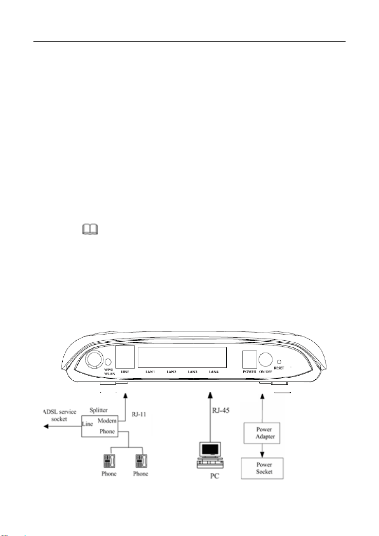
Connection 1: Figure 3 shows the connection of the device, PC, splitter, and
telephone set,
connection is recommended.
when no telephone set is placed before the splitter. This type of
6
Page 16
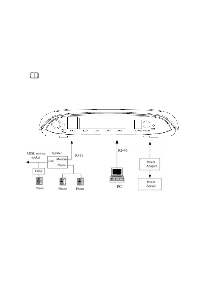
Figure 3 Connection diagram (without a telephone set before the splitter)
Connection 2: Figure 4 shows the connection of the device, PC, splitter, and
telephone set, when a telephone set is placed before the splitter.
As illustrated in the following figure, the splitter is installed close to the device:
Figure 4 Connection diagram (with a telephone set before the splitter)
Note:
When connection 2 is used, the filter must be installed close to the telephone
cable. See Figure 4. Do not use a splitter to replace the filter.
alling a telephone directly before the splitter may lead to failure of connection
Inst
between the device and the central office, failure of Internet access, or slow
connection speed. If you need to add a telephone set before the splitter, you must
add a microfilter before the telephone set. Do not connect several telephones
before the splitter or connect several telephones with the microfilter.
7
Page 17
3 Web Configuration
This chapter describes how to configure the device by using the Web-based
configuration utility.
3.1 Accessing the Device
The following describes how to access the device for the first time in detail.
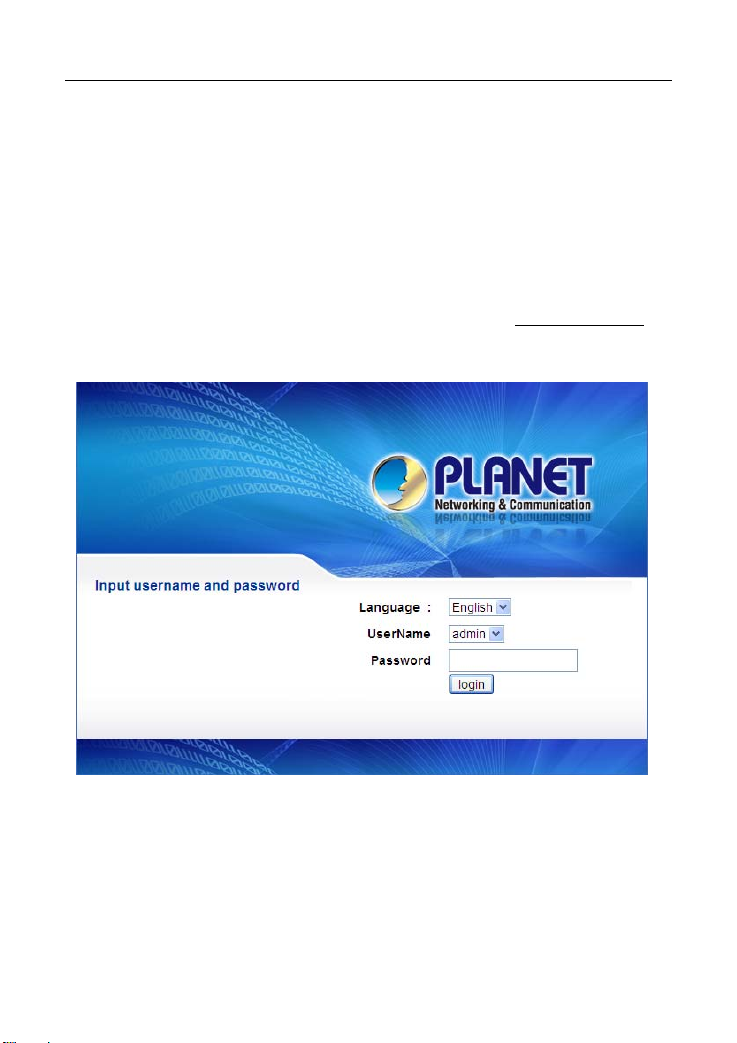
Step 1 Open the Internet Explorer (IE) browser and enter http://192.168.1.1
in the address bar.
Step 2 The LOGIN page as shown in the following figure appears:
In this page, enter the user name and the password. Then, click login.
The user name and the password of the super user are admin and admin
respectively.
The user name and the password of the normal user are user and user
respectively.
If the login information is incorrect, the page as shown in the following figure
appears:
8
Page 18

Click OK to log in again.
Note:
In the LAN, you can use either of the following two levels of user accounts
(displayed in the user name/password format) to access the device:
admin/admin and user/user.
In the WAN, you can use one of the following three levels of user accounts
(displayed in the user name/password format) to access the device:
admin/admin, user/user, and support/support.
3.2 General Configuration
3.2.1 Wizard
Wizard helps you to fast and accurately configure Internet connection and other
important parameters. The following sections describe these various
configuration parameters.
When subscribing to a broadband service, be aware of the Internect connection
mode. The physical WAN device can be Ethernet, DSL, or both. Technical
information about properties of Internet connection is provided by your Internet
service provider (ISP). For example, your ISP should inform you whether you are
connected to the Internet using a static or dynamic IP address, and the protocol,
such as PPPoA or PPPoE, that you use to communicate on the Internet.
Step 1 Choose Setup > Wizard. The page as shown in the following figure
appears:
9 10
Page 19
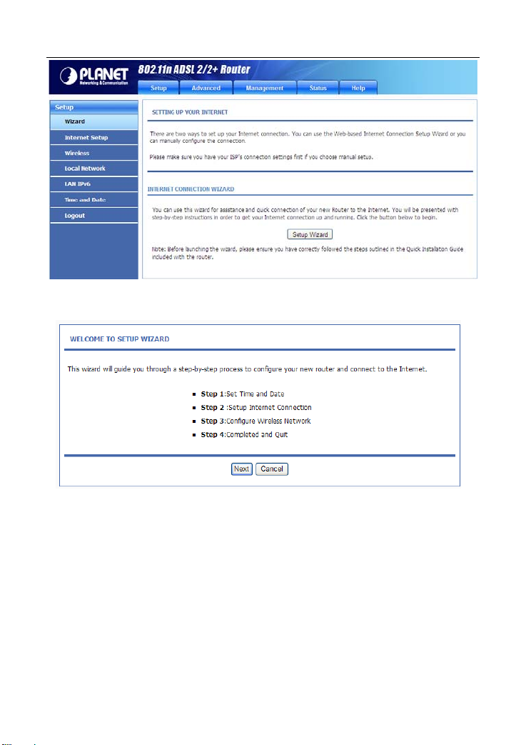
Step 2 Click Setup Wizard. The page as shown in the following figure
appears:
There are four steps to configure the device. Click Next to continue.
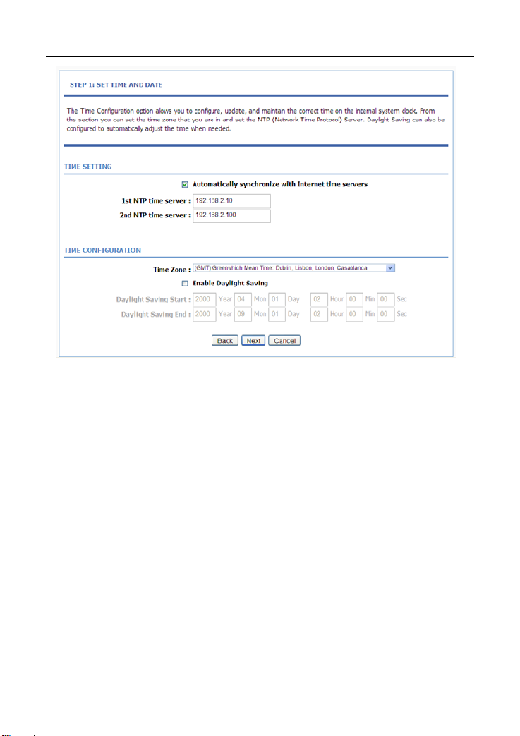
Step 3 Set the time and date. Then, click Next.
Page 20
Step 4 Configure the Internet connection.
Select the protocol and the encapsulation mode. Set the VPI and the
VCI.
If the Protocol is set to PPPoE or PPPoA, the page as shown in the
following figure appears:
11
Page 21
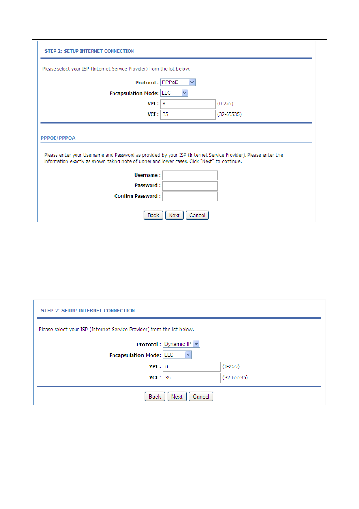
You need to enter the user name and password for PPPoE or PPPoA
dialup.
If the Protocol is set to Dynamic IP, the page as shown in the
following figure appears:
If the Protocol is set to Static IP, the page as shown in the following
figure appears:
12 13
Page 22
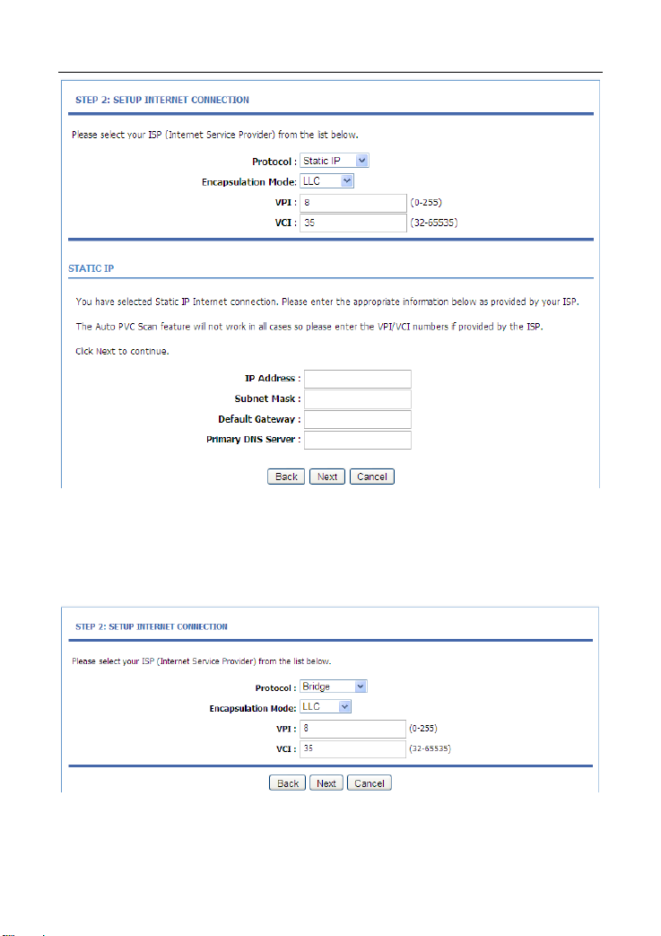
You need to enter the information of the IP address, subnet mask, and
gateway.
If the Protocol is set to Bridge, the page as shown in the following
figure appears:
After setting, click Next.
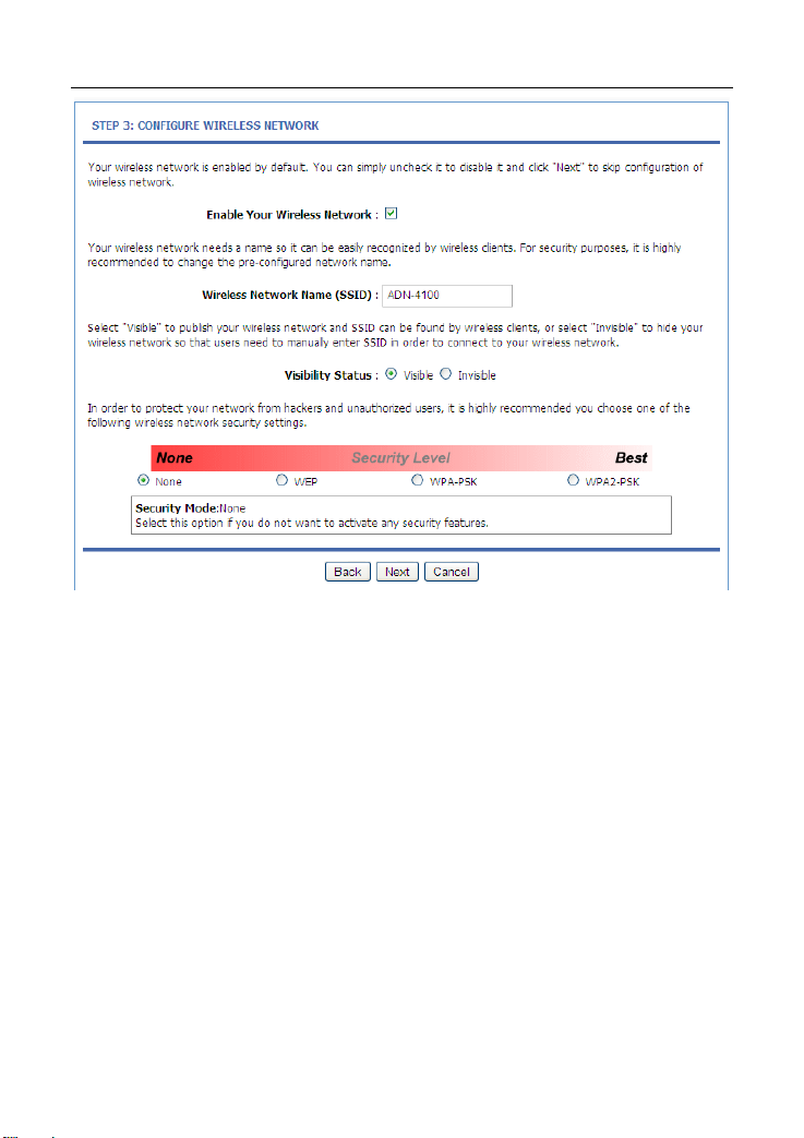
Step 5 Configure the wireless network. Enter the information and click Next.
Page 23
Step 6 View the configuration information of the device. To modify the
information, click Back. To effect the configuration, click Next.
14
Page 24
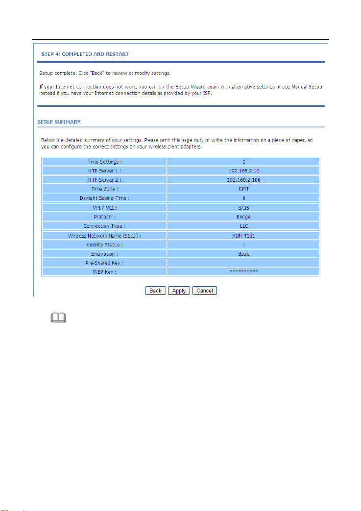
Note:
In each step of the Wizard page, you can click Back to review or modify the
previous settings or click Cancel to exit the wizard.
3.2.2 Internet Setup
Choose Setup > Internet Setup. The page as shown in the following figure
appears:
15
Page 25
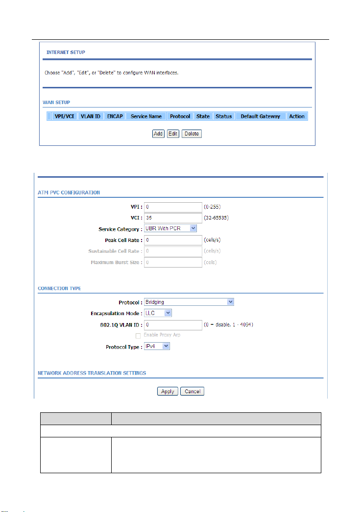
In this page, you can configure the WAN interface of the device.
Click Add and the page as shown in the following figure appears:
The following table describes the parameters in this page.
Field Description
ATM PVC CONFIGURATION
Virtual Path Identifier (VPI) is the virtual path between two
VPI
points in an ATM network. Its value range is from 0 to
255.
16 17
Page 26

Field Description
Virtual Channel Identifier (VCI) is the virtual channel
VCI
Service Category
Peak Cell Rate
Sustainable Cell
Rate
Maximum Burst
Size
CONNECTION TYPE
Protocol
Encapsulation
Mode
802.1Q VLAN ID
Enable Proxy Arp Check this to enable proxy arp.
Protocol Type You can select the IPv4,IPv6 or IPv4&6
NETWORK ADDRESS TRANSLATI ON SETTINGS
Enable NAT
NAT Type
Enable WAN
Service
Service Name
between two points in an ATM network. Its value range is
from 32 to 65535 (0 to 31 is reserved for local
management of ATM traffic).
Select UBR w ith PCR, UBR without PCR, CBR, Non
Realtime VBR, or Realtime VBR from the drop-down list.
Set the maximum transmission rate of the cell in ATM
transmission.
Set the minimum transmission rate of the cell in ATM
transmission.
Set the maximum burst size of the cell in ATM
transmission.
Select PPP over ATM (PPPoA), PPP over Ethernet
(PPPoE), MAC Encryption Routing (MER), IP over
ATM (IPoA), or Bridging from the drop-down list.
Select LLC or VCMUX from the drop-down list. Usually,
you can select LLC.
If you enter a value, packets from the interface is tagged
with the set 802.1q VLAN ID. Its value range is 0-4094,
while 0 indicates to disable this function.
Select or deselect the check box to enable or disable the
NAT connection.
Select Symmetric Nat or Full cone Nat from the
drop-down list
Select or deselect the check box to enable or disable the
WAN connection.
The name to identify the WAN connection. You need not
modify it.
Page 27
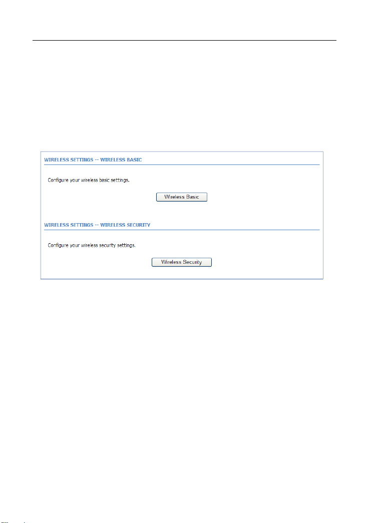
3.2.3 Wireless Setup
This section describes the wireless LAN and some basic configuration. Wireless
LANs can be as simple as two computers with wireless LAN cards
communicating in a pear-to-pear network or as complex as a number of
computers with wireless LAN cards communicating through access points that
bridge network traffic to a wired LAN.
Choose Setup > Wireless. The WIRELESS SETTINGS page as shown in the
following figure appears:
3.2.3.1 Wireless Basics
In the WIRELESS SETTINGS page, click Wireless Basic. The page as shown in
the following figure appears:
18 19
Page 28
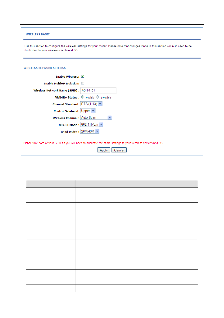
In this page, you can configure the parameters of wireless LAN clients that may
connect to the device.
The following table describes the parameters in this page.
Field Description
Enable Wireless
Enable MultiAP
Isolation
Wireless Network
Name (SSID)
Visibility Status
Channel Standard
Control Sideband You can select Upper or Lower from the list
Select or deselect the check box to enable or disable
the wireless function.
Select or deselect the check box to enable or disable
multiAP isolation. If this function is enabled, clients of
different SSIDs cannot access each other.
Network name. It can contain up to 32 characters. It
can consist of letters, numerals, and/or underlines.
Visible indicates that the device broadcasts the
SSID.
Invisible indicates that the device does not
broadcast the SSID.
You can select from the drop-down list: FCC(1-11),
ETS(1-13), JP(1-14)
Page 29
Field Description
Select the wireless channel used by the device from
Wireless Channel
802.11 Mode
Band Width
Click Apply to save the settings.
the drop-down list. You can select Auto Scan or a
value from CH1—CH13. Auto Scan is recommended.
Select the 802.11 mode of the device from the
drop-down list. The device supports 802.11b, 802.11g,
802.11n, 802.11b/g, 802.11n/g, and 802.11b/g/n.
You can set the bandwidth only in the 802.11n mode.
Y ou can set the bandwidth of the device to 20M or 40M.
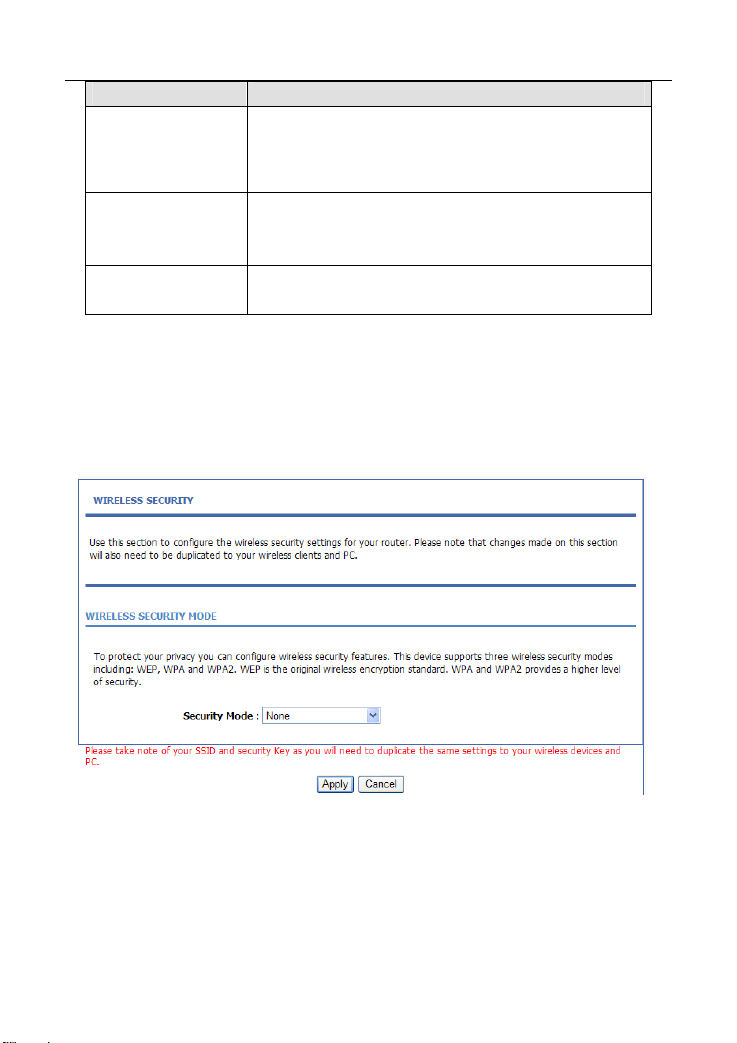
3.2.3.2 Wireless Security
In the WIRELESS SETTINGS page, click Wireless Security. The page as
shown in the following figure appears:
Wireless security is vital to your network to protect the wireless communication
among wireless stations, access points and the wired network. This device
provides the following encryption modes: None, WEP, Auto ( WPA or WPA2),
WPA2 Only, and WPA Only.
WEP
20
Page 30
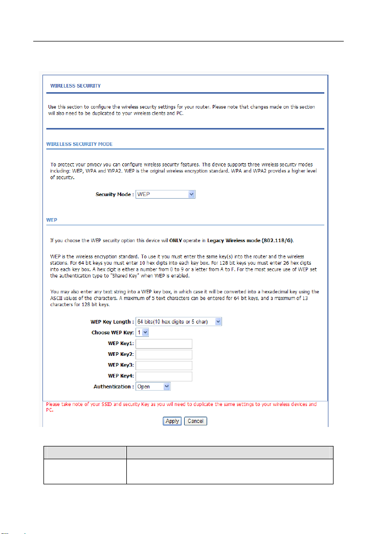
If the Security Mode is set to WEP, the page as shown in the following figure
appears:
The following table describes the parameters in this page.
Field Description
WEP Key Length
You can select 64 bits or 128 bits from the drop-down
list.
21 22
.
Page 31

Field Description
If you select 64 bits, you need to enter 10
hexadecimal numbers or 5 characters.
If you select 128 bits, you need to enter 26
hexadecimal numbers or 13 characters.
Choose WEP Key
WEP Keys 1—4
Authentication
Click Apply to save the settings.
Select the WEP key from the drop-down list. Its value
range is 1—4.
Set the 64 bits or 128 bits key, in the format of Hex or
ASCII.
Select the authentication mode from the drop-down list.
You can select Open or Share Key.
Auto (WPA or WPA2)
If the Security Mode is set to Auto (WPA or WPA2), the page as shown in the
following figure appears:
Page 32

The following table describes the parameters in this page.
Field Description
WPA Mode
WPA Encryption You can select AES or TKIP+AES from the drop-down list.
Group Key
Update Interval
Pre-Shared Key Set the pre-shared key to identify the workstation.
If the WPA Mode is set to Auto (WPA or WPA2)-Enterprise, the page as shown
in the following figure appears:
You can select Auto (WPA or WPA2)-PSK or Auto (WPA
or WPA2)-Enterprise from the drop-down list.
Set the interval for updating the key.
23
Page 33

You need to enter the IP address, port, shared key of the RADIUS server.
Click Apply to save the settings.
WPA2 Only
If the Security Mode is set to WPA2 only, the page as shown in the following
figure appears:
24
Page 34

Parameters in this page are similar to those in the page for Auto (WPA or
WPA2).Click Apply to save the settings.
WPA Only
If the Security Mode is set to WPA only, the page as shown in the following
figure appears:
25
Page 35

Parameters in this page are similar to those in the page for Auto (WPA or
WPA2).
Click Apply to save the settings.
3.2.4 Local Network
You can configure the LAN IP address according to the actual application. The
preset IP address is 192.168.1.1. You can use the default settings and DHCP
service to manage the IP settings of the private network. The IP address of the
device is the base address used for DHCP. To use the device for DHCP in your
26
Page 36

LAN, the IP address pool used for DHCP must be compatible with the IP address
of the device. The IP address available in the DHCP IP address pool changes
automatically if the IP address of the device changes.
You can also enable the secondary LAN IP address. The primary and the
secondary LAN IP addresses must be in different network segments.
Choose Setup > Local Network. The Local Network page as shown in the
following figure appears:
y default, Enable DHCP Server is selected for the LAN interface of the device.
B
DHCP service provides IP settings to workstations configured to automatically
obtain IP settings that are connected to the device through the Ethernet port.
When the device is used for DHCP, it becomes t he default gateway for DHCP
client connected to it. If you change the IP address of the device, you must also
change the range of IP addresses in the pool used for DHCP on the LAN. The IP
address pool can contain up to 253 IP addresses. You can also make DHCP
server just acting on the specific port, by default, those ports are selected.
If your DHCP server doesn’t belong to the same segment with your pc, but you
need to assign IP address from DHCP server, you must uncheck the Enable
27
Page 37

DHCP Server and selected the Enable DHCP Relay to set the DHCP Relay IP
address. And you can also set the preferred and alternate DNS server.
ply to save the settings.
Click Ap
In the DHCP CLIENT CLASS LIST page, you can set an IP address range for some
specification device. The page as shown in the following figure appears:
28
Page 38

The following table describes the parameters in this page.
Field Description
Client Class Name Enter the Client Class name
Min IP Address The IP Address for minimum
Max IP Address The IP Address for maximum
DNS Address Enter the DNS Address with the client class
In the LOCAL NETWORK page, you can assign LAN IP addresses for specific
computers according to their MAC addresses.
Click Add to add static DHCP reservation. The page as shown in the following
figure appears:
The following table describes the parameters in this page.
Field Description
29
Page 39

Field Description
Enable
Computer Name
IP Address Enter the IP address of the computer.
MAC Address Enter the MAC address of the computer.
Click Apply to save the settings.
After the DHCP reservation information is saved, the DHCP reservations list
displays the information. If the DHCP reservations list is not empty, you can
select one or more items and click Edit or Delete.
Select the check box to reserve the IP address for the
designated PC with the configured MAC address.
Enter the computer name. It helps you to recognize the
PC with the MAC address. For example, Father’s
Laptop.
The NUMBE
(PCs or Laptops) currently connected to the device and the detailed information
of the connected computers.
R OF DYNAMIC DHCP CLIENTS page displays the DHCP clients
3.2.5 LAN IPv6
In this page,you can configure the LAN IPv6. Choose Setup > LAN IPv6. The
IPv6 LAN setting page as shown in the following figure appears:
30 31
Page 40

The following table describes the parameters in this page.
Field Description
Start Unique Local
Prefix
Unique Local
GlobalID
Auto get prefix from
WAN
Static Check this to enable the static prefix set.
Site Prefix Type the Prefix address on this item.
Site Prefix Length Means the network ID length, the range is 16-64 bit.
LAN address config
mode
Check this enable the
The default is 11:22:33:44:55
Check this to enable the Auto get prefix from WAN.
You can select the SLAAC and DHCPv6 mode,the
describes as follow:
SLAAC: The PC will obtained the prefix but not
obtained the DNS
DHCPv6:The PC will obtained the prefix and DNS
from DHCPv6
3.2.6 Time and Date
Choose Setup > Time an d Date. The TIME AND DATE page as shown in the
following figure appears:
Page 41

In the TIME AND DATE page, you can configure, update, and maintain the time
of the internal system clock. You can set the time zone that you are in and the
network time protocol (NTP) server. You can also set daylight saving time to
automatically adjust the time when needed.
Select Automatically synchronize with Internet time servers.
Select the appropriate time server and the time zone from the corresponding
drop-down lists.
Select Enable Daylight Saving if necessary. Enter the correct the start and end
time of the daylight saving.
Click Apply to save the settings.
3.2.7 Logout
Choose Setup > Logout. The page as shown in the following figure appears:
32
Page 42

Click Logout to log out of the configuration page.
3.3 Advanced Configuration
This section contains advanced features used for network management, security
and administrative tools to manage the device. You can view the st atus and other
information of the device, to examine the performance and troubleshoot.
3.3.1 Advanced Wireless
This function is used to modify the standard 802.11g wireless settings. It is
recommended not changing the default settings, because incorrect settings may
affect the performance of the wireless performance. The default settings provide
the best wireless performance in most environments.
Choose Advanced > Advanced Wireless. The ADVANCED WIRELESS page
as shown in the following figure appears:
33
Page 43

3.3.1.1 Advanced Settings
In the ADVANCED WIRELESS page, click Advanced Settings. The page as
shown in the following figure appears:
34
Page 44

35 36
Page 45

The following table describes the parameters in this page.
Field Description
ADVANCED WIRELESS SETTINGS
Transmission Rate
Multicast Rate
Transmit Power
Beacon Period
RTS Threshold
Fragmentation
Threshold
DTIM Interval
Preamble Type
SSID
Enable Wireless
SSID
Visibility Status
User Isolation
Select the transmission rate of the wireless network
from the drop-down list.
Select the multicast transmission rate of the wireless
network from the drop-down list. You can select Lower
or Higher.
Select the power for data transmission from the
drop-down list. You can select 100%, 80%, 60%, 40%,
or 20%.
By default, the wireless beacon frame sends the data
once every 100ms. Its value range is 20—1024.
The threshold of transmission request. Its value range
is 0—2347 and the default value is 2346.
Its value range is 256—2346 and the default value is
2345.
Data beacon proportion (transmission quantity
indication). Its value range is 1—255 and the default
value is 100.
Select the preamble code from the drop-down list. You
can select long or short.
Select or deselect the check box to enable or disable
the wireless function.
Set the wireless network name, that is, SSID. SSID is
used to distinguish different wireless networks.
Select whether to hide the AP. You can select Visible
or Invisible. If you select Invisible, the AP is hidden
and the terminal cannot obtain the SSID through
passive scanning.
Select whether users of the AP can communicate with
each other. You can select Off or On from the
drop-down list. On indicates that computers connected
to the device cannot communicate with each other.
Page 46

Field Description
WMM Advertise
Max Clients
SSID1—3
Enable Wireless
Guest Network
SSID Similar to the primary SSID, it identifies a wireless AP.
These settings are applicable only for more technically advanced users who have
sufficient knowledge about wireless LAN. Do not change these settings unless
you know the effect of changes on the device.
Click Apply to save the settings.
Select whether to enable WMM. You can select Off or
On.
Set the maximum number of clients that can be
connected to the AP at the same time. Its value range
is 1—32.
Select or deselect the check box to enable or disable
the wireless interface.
3.3.1.2 MAC Filtering
In the ADVANCED WIRELESS p age, click MA C F ilt er in g . The page as shown in
the following figure appears:
Click Add and the page as shown in the following figure appears:
37 38
Page 47

The following table describes the parameters in this page.
Field Description
MAC Address
Click Apply to save the settings.
Enter the MAC address of another device that is
included in MAC filtering.
3.3.1.3 Security Settings
In the ADVANCED WIRELESS page, click Security Settings. The page as shown
in the following figure appears:
Select the desired SSID from the drop-down list.
Select the encryption type from the Security Mode drop-down list. You can
select None, WEP, AUTO (WPA or WPA2), WPA Only, or WPA2 Only. For
parameters of different encryption types, see section.3.2.3.2 Wireless Security
Page 48

Click Apply to save the settings.
3.3.1.4 WPS Settings
In the ADVANCED WIRELESS page, click WPS Setting. The WIRELESS WPS
page as shown in the following figure appears:
Enabled: The WPS service is enabled by default.
Note:
Ensure that the network card supports the WPS function.
Field Description
Select Mode Select Enrollee or Registrar from the drop-down list.
Configuration State
Input Station PIN
Select Configured or unconfigured from the
drop-down list.
If you are using the PIN method, you need a Registrar,
either an access point or a wireless router, to initiate the
registration between a new device and an active access
point or a wireless router.
39
Page 49

You can use one of the following there methods to use WPS authentication:
Press the WPS button on the side panel for 3 seconds.
In the WIRELESS WPS page, click PBC. It has the same function of the
WPS button on the side panel. This is an optional method on wireless
clients.
Note:
You need a Registrar when using the PBC method in a special case in
which the PIN is all zeros.
3.3.1.5 WDS Settings
In the ADVANCED WIRELESS page, click WDS Settings. The WIRELESS
WDS page as shown in the following figure appears:
The Wireless repeater function can make the WLAN signal cover m
the blanks and then Apply.
ore area. Fill
3.3.2 Port Forwarding
This function is used to open ports in your device and re-direct data through
these ports to a single PC in your network (WAN-to-LAN traffic). It allows remote
users to access services in your LAN, such as FTP for file transfers or SMTP, and
POP3 for e-mail. The device receives remote requests for these services at your
40
Page 50

public IP address. It uses the specified TCP or UDP protocol and port, and
redirects these requests to the server on your LAN with the specified LAN IP
address. Note that the specified private IP address must be within the available
IP address range of the subnet where the device is in.
Choose Advanced > Port Forwarding. The page as shown in the following
figure appears:
Click Add to add a virtual server. See the following figure:
41 42
Page 51

Select a service for a preset application or enter the name in the Custom Server
field.
Enter an IP address in the Server IP Address field, to appoint the corresponding
PC to receive forwarded packets.
The port table displays the ports that you want to open on the device. The
Protocol indicates the type of protocol used by each port.
Click Apply to save the settings. The page as shown in the following figure
appears. A virtual server is added.
Page 52

3.3.3 DMZ
Choose Advanced > DMZ. The page as shown in the following figure appears:
In this page, you can enable a DMZ host. In this way, access from Internet to the
WAN IP address of the device is forwarded to the DMZ host and network server
of the internal LAN is protected.
Click Apply to save the settings.
43
Page 53

3.3.4 Parental Control
Choose Advanced > Parental Control. The PARENTAL CONTROL page as
shown in the following figure appears:
This page provides two useful tools for restricting Internet access. Block
Website allows you to quickly cr eate a list of websites that you wish to prevent
users from accessing. MAC Filter allows you to control Internet access by clients
or PCs connected to the device.
3.3.4.1 Block Website
In the PARENTAL CONTROL page, click Block Website. The page as shown in
the following figure appears:
Click Add. The page as shown in the following page appears:
44
Page 54

Enter the website in the URL field. Select the time to block websites from the
Schedule drop-down list, or select Manual Schedule and set the corresponding
time and days.
Click Apply to add the website to the BLOC K WEBSITE table. The page as
shown in the following figure appears:
3.3.4.2 MAC Filter
In the PARENTAL CONTROL page, click MAC Filter. The page as shown in the
following figure appears:
45 46
Page 55

Click Add. The page as shown in the following figure appears:
The following table describes the parameters in this page.
Field Description
User Name
Current PC’s MAC
Address
Other MAC Address
Enter the name that identifies your configuration. For
example, kids.
Enter the MAC address of the computer that connects
to the device.
Enter the MAC address of another device that is
included in MAC filtering.
Page 56

Field Description
Schedule
Manual Schedule
Enter the use name and MAC address. Select the corresponding time and days.
Then, click Apply to add the MAC address to the BLOCK MAC ADDRESS table.
The page as shown in the following figure appears:
Select the time of MAC filter from the drop-down list.
You can select always or never.
If you select this check box, you need to manually set
the time of MAC filtering.
3.3.5 Filtering Options
Choose Advanced > Filtering Options. The FILTERING OPTIONS page as
shown in the following figure appears:
47 48
Page 57

3.3.5.1 IP Filtering
In the Filtering Options page, click IP Filtering. The FIREWALL page as shown
in the following figure appears:
Click Add to add an IP filter. The page as shown in the following figure appears:
Page 58

Field Description
Name Enter the name that identifies your configuration.
Interface
Type Select the In, Out or Both from the drop-down list.
Default action Select the Permit or Drop from the drop-down list.
Default Chain
After set the firewall info finish, click Add Ru le to add an IP filter rule. The page
as shown in the following figure appears:
Select LAN or the other connection from the drop-down
list.
Select the Local, Forward or Both from the
drop-down list.
49
Page 59

Check the Enabled and specify at least one of the following criteria: protocol,
source/destination IP address, subnet mask, and source/destination port.
Then, click Apply to save the settings.
Note:
The settings apply only when the firewall is enabled.
50
Page 60

3.3.5.2 Bridge Filtering
In the FILTERING OPTIONS page, click Bridge Filtering. The page as sh own in
the following figure appears:
This page is used to configure bridge parameters. In this page, you can modify
the settings or view the information of the bridge and its attached ports.
Click Add to add a bridge filter. The page as shown in the following figure
appears:
The following table describes the parameters in this page.
Field Description
Protocol Type Select the protocol type to be mapped from the
51
Page 61

Field Description
drop-down list. You can select PPPoE , IPv4, IPv6,
AppleTalk, IPX, NetBEUI, or IGMP.
Destination MAC
Address
Source MAC
Address
Frame Direction
Time schedule
Wan interface
Click Apply to save the settings.
Enter the destination MAC address to be mapped.
Enter the source MAC address to be mapped.
Select the frame direction to be mapped from the
drop-down list. The device supports frame direction
from LAN to WAN and WAN to LAN.
Select the time that you want to apply the rule from the
drop-down list. You can select Always or Never.
Select the WAN interface to be mapped from the
drop-down list.
3.3.6 QoS Configuration
Choose Advanced > QoS Configuration. The page as shown in the following
figure appears:
52
Page 62

3.3.6.1
In the QoS Configuration page, click QoS Global Option. The page as shown
in the following figure appears:
In this p
Queuing Operation.
QoS Global Option
age, you can select or deselect the check box to enable or disable the
3.3.6.2 Queue Configuration
In the QoS Configuration page, click Qos Queue Configuration. The page as
shown in the following figure appears:
In this p
bandwidth of each interface. The uplink rate and the downlink rate are limited
according to the configured bandwidth. You also can set the priority of the queue.
age, you can configure the upstream bandwidth and downstream
53
Page 63

The device supports the following four priority levels: 1,2,3,4. Click Submit to
save the settings.
3.3.6.3 Classification Configuration
In the QoS Configuration page, click QoS Classification Configuration. Click
Add and the page as shown in the following figure appears:
The follo
wing table describes the parameters in this page.
Field Description
Classify Type
Enable Select or deselect the check box to enable or disable
You can select Upstream Flow Classify or
Downstream Flow Classify
54 55
Page 64

Field Description
QoS classification.
SPECIFY TRAFFIC CLASSIFICATION RULES
Select the physical port of the packet from the
Input Interface
Source MAC Address Enter the source MAC address of the packet.
Source MAC Mask
802.1P
Source IPv4 Address Enter the Source IP address of the packet.
Source subnet mask Enter the Source subnet mask of the packet.
Destination IPv4
Address
Destination subnet
mask
Ethernet Type
DSCP check
Protocol Type Select the protocol on this column.
Source port range Enter the source port range of the packet.
Destination port range Enter the destination port range of the packet.
CLASSIFY MATCH RESULT
Classify Queue
DSCP Mark Attach the DSCP mark to the mapped packet.
Cos Mark Attach the 802.1p mark to the mapped packet.
Click Submit Apply to save the settings.
drop-down list. For example, ethernet1, ethernet2,
ethernet3, and ethernet4.
Use mask 000000ffffff to mask the MAC address. 00
indicates not mapped and ff indicates mapped.
Select the 802.1p priority of the packet from the
drop-down list. You can select Not match or a value
in the range of 0—7. Note that this function is not
supported at the moment.
Enter the destination IP address of the packet.
Enter the destination subnet mask of the packet.
Select the layer 2 protocol type from the drop-down
list. For example, IP protocol and IPX protocol.
You can use this feature to differentiate the complex
data type from the drop-down list.
Specify the queue to which the packet belongs. You
can set the queue in the classification configuration.
Page 65

3.3.7 Firewall Settings
A denial-of-service (DoS) attack is one of the most common network attacks and
is characterized by an explicit attempt by attackers to prevent legitimate users of
a service from using that service. It usually leads to overload of system server or
core dump of the system.
Choose Advanced > Firewall Settings. The page as shown in the following
figure appears:
Click Apply to save the settings.
3.3.8 DNS
Domain name system (DNS) is an Internet service that translates domain names
into IP addresses. Because domain names are alphabetic, they are easier to
remember. The Internet, however, is actually based on IP addresses. Each time
you use a domain name, a DNS service must translate the name into the
corresponding IP address. For example, the domain name www.example.com
might be translated to 198.105.232.4.
56
Page 66

The DNS system is, in fact, its own network. If one DNS server does not know
how to translate a particular domain name, it asks another one, and so on, until
the correct IP address is returned.
Choose Advanced > DNS. The page as shown in the following figure appears:
The following table describes the parameters in this page.
Field Description
Wan Connection
Obtain DNS server
address automatically
Use the following
DNS server
addresses
Preferred DNS server Enter the IP address of the primary DNS server.
Alternate DNS server
Click Apply to save the settings.
Select the WAN interface of the DNS server to be
connected from the drop-down list.
If you select this radio button, the device
automatically obtains IP address of the DNS server
from the ISP. You need not manually enter the IP
address of the server.
If you select this radio button, you need to manually
enter the IP address of the server provided by the ISP .
Enter the IP address of the secondary DNS server. If
the primary DNS server fails to work, the device tries
to connect the secondary DNS server.
57
Page 67

3.3.9 Dynamic DNS
The device supports dynamic domain name service (DDNS). The dynamic DNS
service allows a dynamic public IP address to be associated with a static host
name in any of the many domains, and allows access to a specified host from
various locations on the Internet. Click a hyperlinked URL in the form of
hostname.dyndns.org and allow remote access to a host. Many ISPs assign
public IP addresses using DHCP, so locating a specific host on the LAN using the
standard DNS is difficult. For example, if you are running a public web server or
VPN server on your LAN, DDNS ensures that the host can be located from the
Internet even if the public IP address changes. DDNS requires that an account
be set up with one of the supported DDNS service providers (DyndDNS.org or
Dlinkddns.com).
Choose Advanced > Dynamic DNS. The page as shown in the following page
appears:
Click Add to add dynamic DNS. The page as shown in the following figure
appears:
58
Page 68

The following table describes the parameters in this page.
Field Description
DDNS provider
Hostname
Interface
Username Enter the user name of your DDNS account.
Password Enter the password of your DDNS account.
Click Apply to save the settings.
Select the DDNS provider from the drop-down list. You
can select DynDns.org, TZO, or GnuDIP.
Enter the host name that you register with your DDNS
provider.
Select the interface that is used for DDNS service from
the drop-down list. The IP address of the interface
corresponds to the host name.
3.3.10 Network Tools
Choose Advanced > Network Tools. The NETWORK TOOLS page as shown in
the following figure appears:
59
Page 69

age contains the following function items: Port Mapping, IGMP Proxy,
This p
IGMP Snooping, UPnP, ADSL, SNMP, TR-069, Certificates, PPTP.and IPSec
60
Page 70

3.3.10.1
Port Mapping.
In the NETWORK TOOLS page, click Port Mapping. The page as shown in the
following figure appears:
In this page, you can bind the WAN interface and the LAN interface to the same
group. Click Add to add port mapping. The page as shown in the following figure
appears:
61
Page 71

To create a mapping group, do as follows:
Step 1 Enter the group name.
Step 2 Select interfaces from the Available Interfaces list and click the <-
arrow button to add them to the Grouped Interfaces list, in this way,
you can create the required mapping of the ports. The group name
must be unique.
Step 3 Click Apply to save the settings.
3.3.10.2 IGMP Proxy
In the NETWORK TOOLS page, click IGMP Proxy. The page as shown in the
following figure appears:
62
Page 72

IGMP proxy enables the device to issue IGMP host messages on behalf of hosts
that the system discovered through standard IGMP interfaces. The device serves
as a proxy for its hosts after you enable the function.
Select Enable IGMP Proxy and select the desired WAN and click Apply to save
the settings.
3.3.10.3 IGMP Snooping
When IGMP snooping is enabled, only hosts that belong to the group receive the
multicast packets. If a host is deleted from the group, the host cannot receive the
multicast packets any more.
In the NETWORK TOOLS page, click IGMP Snooping. The page as shown in
the following figure appears:
63
Page 73

Click Apply to save the settings.
3.3.10.4 UPnP
In the NETWORK TOOLS page, click Upnp. The page as shown in the following
figure appears:
In this page, you can enable universal plug and play (UPnP) and then the system
serves as a daemon.
UPnP is widely applied in audio and video software. It automatically searches
devices in the network. If you are concerned about UPnP security, you can
disable it. Select the WAN and LAN interfaces at which you want to enable UPnP
and click Apply to save the settings.
64
Page 74

3.3.10.5
ADSL Settings
In the NETWORK TOOLS page, click ADSL. The page as shown in the following
figure appears:
In this page, you can select the ADSL modulation. Normally, you are
recommended to keep the factory defaults. The device supports the following
modulation types: G.Dmt, G.lite, T1.413, ADSL2, AnnexL, ADSL2+, and AnnexM.
The device negotiates the modulation mode with the DSLAM.
Click Apply to save the settings.
3.3.10.6 SNMP
In the NETWORK TOOLS page, click SNMP. The page as shown in the following
figure appears:
65
Page 75

In this page, you can set the SNMP parameters. The following table describes
the parameters in this page.
Field Description
Enable SNMP Agent
Read Community
Set Community
Trap Manager IP
Trap Community
Trap Version
Click Apply to save the settings.
Select or deselect the check box to enable or disable
SNMP agent.
Universal character to obtain the device information. It
is similar to the password. The SNMP application entity
can use it to directly obtain the device information.
Universal character to modify the device configuration.
It is similar to the password. The SNMP application
entity can use it to directly modify the device
configuration.
Enter the address of the server that receives the trap
message.
The field that is included in the trap message sent by
the device.
Select the trap version from the drop-down list. Y ou can
select v1 or v2c.
66
Page 76

3.3.10.7
TR-069
In the NETWORK TOOLS page, click TR-069. The page as shown in the
following figure appears:
age, you can configure the TR-069 CPE. The following table describes
In this p
the parameters in this page.
Field Description
TR069 Configuration
Inform
ou can select Disabled or Enabled to disable or enable
R-069 configuration.
You can select Disabled or Enabled to disable or
enable notification.
Disabled indicates that the device does not
automatically send requests to the TR069 server.
Enabled indicates that the device automatically
sends a request of connection to the TR069
server. The following function items are available
only when Inform is set to Enabled. The interval
67
Page 77

Field Description
of sending a request of connection to the TR069
server from the device.
Inform Interval
ACS URL
ACS User Name
ACS Password
Connection Request
Authentication
Connection Request
User Name
Connection Request
Password
Click Apply to save settings.
The path of the TR069 server to which the device
sends a request.
The user name that the devices uses to log in to the
TR069 server.
The password that the devices uses to log in to the
TR069 server.
Select the check box to enable authentication of
connection request. If you enable the function, you
need to enter the user name and password for
authentication.
The user name that the TR069 server uses to access
the TR069 progress of the device.
The password that the TR069 server uses to access
the TR069 progress of the device.
3.3.10.8 Certificates
In the NETWORK TOOLS page, click Certificates. The Certificates page as
shown in the following figure appears:
Click Trusted CA and the page as shown in the following figure appears:
68
Page 78

Note:
Before importing a certificate, you must synchronize the system time with
time server. Otherwise, the certificate fails to be imported.
Click Input Certificate to import a certificate. The page as shown in the following
figure appears:
69
Page 79

3.3.10.9
The Point-to-Point Tunneling Protocol (PPTP) is a method for implementing
virtual private networks. PPTP uses a control channel over TCP and a GRE
tunnel operating
In the NETW
figure appears.
PPTP
to encapsulate PPP packets.
ORK TOOLS page, click PPTP, the page as shown in the following
The following table describes the parameters in this page.
Field Description
Local IP Start The started IP address of the local network.
The valid numbers of local IP addresses. It works
Local IP Num
Remote IP Start The started IP address of the remote network.
Remote IP Num
Netmask It is valid for both the local network and the remote
together with the Local IP Start to determine the range
of the local IP addresses.
The valid numbers of remote IP addresses. It works
together with the Remote IP Start to determine the
range of the remote IP addresses.
70
Page 80

Field Description
network.
Clicks add, the page as shown in the following figure appears.
The following table describes the parameters in this page.
Field Description
Username
Password
The user name that is used for dialup to connect the
modem to the PPTP.
The password that is used for dialup to connect the
modem to the PPTP.
3.3.10.10 IPSec
In the NETWORK TOOLS page, click IPSEC. The page as shown in the
following figure appears.
In this page, you can add, edit and delete the IPSec tunnel connections
Select Enable IPSEC, and click Add, the page as shown in the following figure
appears.
71
Page 81

72
Page 82

Field Description
IPSec Connection
Name
Tunnel Mode You can select ESP or AH.
Remote IPSec
Gateway Address
Tunnel access from
local IP address
IP Address for VPN If you select Single Address, it is the IP address of
IP Subnetmask Enter the subnetmask for IP.
Tunnel access from
remote IP address
Key Exchange Method
The connection name of the marker IPSec.
The IP or domain name of the Remote IPSec
Gateway.
You can select Subnet or Single Address.
If you select Single Address, it allows only one PC
from local to connect remote hosts with IPSEC
mode. You must enter the IP address of the PC in
fourth item.
If you select subnet, it allows more than one PC
from local to connect remote hosts with IPSEC
mode.
the PC. If you choose Subnet, it is the subnet
address.
You can select Subnet or Single Address.
You can select from the drop-down list.
Pre-Shared Key Enter the pre-shared key.
IKE Settings
You can select from the drop-down list.
Mode
Encryption Algorithm You can select from the drop-down list.
73
Page 83

Field Description
You can select from the drop-down list.
Integrity Algorithm
You can select from the drop-down list.
Diffie-Hellman Group
Key Exchange
Key Life Time Enter the time of key life.
Use Interface Select the use interface
This is a dynamic page. The displays are different (some options are shown and
hidden) when different types or connections are chosen.
In this page, set the parameters such as the IPSec connection name, tunnel
mode, and remote IPSec gateway address.
After finishing setting, click Apply to save the settings.
74
Page 84

3.3.11 Routing
Choose Advanced > Routing. The page as shown in the following page
appears:
This page contains the following function items: Static Route, Policy Router and
Default Gateway.
3.3.11.1 Static Route
Choose Advanced > Routing and click Static Route. The page as shown in the
following figure appears:
75
Page 85

This page displays the information of existing static routes. Click Add and the
page as shown in the following figure appears:
The following table describes the parameters in this page.
Field Description
Destination Network
Address
Subnet Mask The subnet mask of the destination IP address.
Use Gateway IP
Address
Use Interface
Note: You can enter the gateway IP address of the device in the Use
Gateway IP Address field or set the User Interface, but cannot apply the two
settings at the same time.
The destination IP address of the device.
The gateway IP address of the device.
Select the interface of the static routing used by the
device from the drop-down list.
3.3.11.2 Policy Route
Choose Advanced > Routing and click Policy Route. Click Add and the page
as shown in the following figure appears:
76
Page 86

In this page, you can select the interfaces on your device that use RIP of the
protocol used.
If you enable RIP, the device communicates with other devices using the routing
information protocol (RIP).Click Apply to save the settings.
3.3.11.3 Default Gateway.
Choose Advanced > Routing and click Default Gateway. The page as shown in
the following figure appears:
In this page, you can select Enable Automatic Assigned Default Gateway, or
enter the information in the Use Gateway IP Address and Use Interface fields.
Click Apply to save the settings.
3.3.12 Schedules
Choose Advanced > Schedules. The page as shown in the following figure
appears:
77
Page 87

Click Add to add a schedule rule. The page as shown in the following figure
appears:
The following table describes the parameters in this page.
Field Description
Name Set the name of the schedule.
Day(s)
All Day – 24 hrs
Start Time Set the start time of the firewall.
End Time Set the end time of the firewall.
Click Apply to save the settings.
You can select one, more, or all of the seven days in a
week.
If you select the check box, the rule applies throughout
the 24 hours of the day.
78
Page 88

3.3.13 NAT
Choose Advanced > NAT. The page as shown in the following figure appears:
raditional NAT would allow hosts within a Internal network to transparently
T
access hosts in the external network, you can select Single IP or IP Range with
the Internal and External IP type and enter the Internal and External IP address
to decide witch Internal IP address transparently the specify External IP address.
3.3.14 Logout
Choose Advanced > Logout. The page as shown in the following figure
appears:
79
Page 89

Click Logout to log out of the configuration page.
3.4 Management
3.4.1 System
Choose Management > System Management. The System page as shown in
the following figure appears:
In this page, you can restart the device, back up the current settings to a file,
update the backup file, and restore the factory default settings.
80
Page 90

The following table describes the buttons in this page.
Button Description
Reboot Restart the device.
Specify the path to back up the current configuration in
Backup Setting
Update Settings
Restore Default
Setting
Caution:
Do not turn off your device or press the Reset button when the procedure
ogress.
is in pr
a configuration file on your computer. You can rename
the configuration file.
Click Browse… to select the configuration file of device
and click Update Settings to update the configuration
of the device.
Reset the device to default settings.
3.4.2 Firmware Update
Choose Management > Firmw are Update. The page as shown in the following
figure appears:
81 82
Page 91

In this page, you can upgrade the firmware of the device. T o update the firmware,
do as follows:
Step 1 Click Browse…to select the file.
Step 2 Select Clear Config.
Step 3 Click Update Firmware to update the configuration file.
The device loads the file and reboots automatically.
Caution:
Do not turn off your device or press the Reset button when the procedure
ogress.
is in pr
3.4.3 Access Controls
Choose Management > Access Controls. The ACCESS CONTROLS page as
shown in the following figure appears:
Page 92

This page contains Account Password, Services, and IP Address.
3.4.3.1 Account Password
In the ACCESS CONTROLS page, click Account Password. The page as
shown in the following figure appears:
Figure 5
In this page, you can change the password and set the time for automatic logout.
You are recommended to change the default password to ensure the security of
your network. Ensure that you remember the new password or write it down and
keep it in a safe location for future reference. If you forget the password, you
need to reset the device to the factory default settings. In that case, all
configuration settings of the device are lost.
The following table describes the parameters in this page.
Field Description
83
Page 93

Field Description
ACCOUNT PASSWORD
Username
New Username Enter the new username.
Current Password Enter the password of the user.
New Password Enter the new password.
Confirm Password Enter the new password again for confirmation.
WEB IDLE TIME OUT SETTINGS
Web Idle Time Out
Click Apply to apply the settings.
Select a user name from the drop-down list to access
the device. You can select admin, user.
Set the time after which the system automatically exits
the configuration page. Its value range is 5—30
minutes.
3.4.3.2 Services
In the ACCESS CONTROLS page, click Services. The page as shown in the
following figure appears:
84
Page 94

In this page, you can enable or disable the services that are used by the remote
host. For example, if telnet service is enabled at port 23, the remote host can
access the device by telnet through port 23.
Select the management services that you want to enable or disable at the LAN or
WAN interface and click Apply to apply the settings.
Caution:
If you disable the HTTP service, you cannot access the configuration
age of the device any more.
p
3.4.3.3 IP Address
In the ACCESS CONTROLS page, click IP Address. The page as shown in the
following figure appears:
In this page, you can configure the IP address in the access control list (ACL). If
ACL is enabled, only devices of the specified IP addresses can access the
device.
Select Enable Access Control Mode to enable ACL.
Note:
If you enable ACL, ensure that the IP address of the host is in the ACL list.
85
Page 95

Click Add. The page as shown in the following figure appears:
Enter the IP address of the desired device in the IP Address field and click
Apply to apply the settings.
3.4.4 Diagnostics
Choose Management > Diagnosis. The page as shown in the following figure
appears:
This page contains WAN Diagnostics and Ping Diagnostics.
3.4.4.1 WAN Diagnostics
In the Diagnosis page, click WAN Diagnostics. The page as shown in the
following figure appears:
In this p
Diagnostic Test to run diagnostics. The page as shown in the following figure
appears:
age, you can test the connection status of the device. Click Run
86 87
Page 96

3.4.4.2 Ping Diagnostics
In the Diagnosis page, click Ping Diagnostics. The page as shown in the
following figure appears:
Page 97

In this page, you can test the IP address on the same segment connect status of
the device. Click Ping to run diagnostics.
3.4.5 Log Configuration
Choose Management > Log Configuration. The SYSTEM LOG page as shown
in the following figure appears:
In this page, you can enable the log function. You can set Mode to Local,
Remote, or Both. Local indicates to save the log in the local computer. Remote
indicates to send the log to the remote log server. Both indicate to save the log in
the local computer and the remote log server.
To log the events, do as follows:
Step 1 Select Enable Log.
Step 2 Select a mode from the drop-down list.
If you select Remote or Both, enter the IP address and port number of
the server.
Step 3 Click Apply to apply the settings.
Step 4 Click View System Log or View Firewall Log to view the detail
information of the system log.
88
Page 98

3.4.6 Logout
Choose Management > Logout. The page as shown in the following figure
appears:
Click Logout to log out of the configuration page.
3.5 Status
In the Status page, you can view the system information and monitor the
performance of the device.
3.5.1 Device Information
Choose Status > Device Info. The page as shown in the following figure
appears:
89
Page 99

90
Page 100

The page displays the summary of the device status, including the system
information, WAN connection information, wireless information, and local network
information.
3.5.2 Wireless Clients
Choose Status > Wireless Clients. The page as shown in the following page
appears:
The page displays authenticated wireless stations and their statuses.
3.5.3 DHCP Clients
Choose Status > DHCP Clients. The page as shown in the following page
appears:
This page displays all client devices that obtain IP addresses from the device.
You can view the host name, IP address, MAC address, and expiration time of
the IP address.
91
 Loading...