

Page 1

Wired ADSL 2/2+ Router
ADE-3400v4 / ADE-4400v4
User's Manual
1
Page 2

Copyright
Copyright© 2009 by PLANET Technology Corp. All rights reserved. No part of this publication
may be reproduced, transmitted, transcribed, stored in a retrieval system, or translated into any
language or computer language, in any form or by any means, electronic, mechanical, magnetic,
optical, chemical, manual or otherwise, without the prior written permission of PLANET.
PLANET makes no representations or warranties, either expressed or implied, with respect to the
contents hereof and specifically disclaims any warranties, merchantability or fitness for any particular
purpose. Any software described in this manual is sold or licensed "as is". Should the programs
prove defective following their purchase, the buyer (and not this company, its distributor, or its dealer)
assumes the entire cost of all necessary servicing, repair, and any incidental or consequential damages
resulting from any defect in the software. Further, this company reserves the right to revise this
publication and to make changes from time to time in the contents hereof without obligation to notify
any person of such revision or changes.
All brand and product names mentioned in this manual are trademarks and/or registered trademarks
of their respective holders.
Federal Communication Commission Interference Statement
This equipment has been tested and found to comply with the limits for a Class B digital device,
pursuant to Part 15 of FCC Rules. These limits are designed to provide reasonable protection against
harmful interference in a residential installation. This equipment generates, uses, and can radiate
radio frequency energy and, if not installed and used in accordance with the instructions, may cause
harmful interference to radio communications. However, there is no guarantee that interference will
not occur in a particular installation. If this equipment does cause harmful interference to radio or
television reception, which can be determined by turning the equipment off and on, the user is
encouraged to try to correct the interference by one or more of the following measures:
1. Reorient or relocate the receiving antenna.
2. Increase the separation between the equipment and receiver.
3. Connect the equipment into an outlet on a circuit different from that to which the receiver is
connected.
4. Consult the dealer or an experienced radio technician for help.
FCC Caution
To assure continued compliance (example-use only shielded interface cables when connecting to
computer or peripheral devices). Any changes or modifications not expressly approved by the party
responsible for compliance could void the user’s authority to operate the equipment.
This device complies with Part 15 of the FCC Rules. Operation is subject to the Following two
conditions: (1) This device may not cause harmful interference, and (2) this Device must accept any
interference received, including interference that may cause undesired operation.
2
Page 3

Federal Communication Commission (FCC) Radiation Exposure Statement
This equipment complies with FCC radiation exposure set forth for an uncontrolled environment. In
order to avoid the possibility of exceeding the FCC radio frequency exposure limits, human
proximity to the antenna shall not be less than 20 cm (8 inches) during normal operation.
R&TTE Compliance Statement
This equipment complies with all the requirements of DIRECTIVE 1999/5/EC OF THE
EUROPEAN PARLIAMENT AND THE COUNCIL OF 9 March 1999 on radio equipment and
telecommunication terminal Equipment and the mutual recognition of their conformity (R&TTE)
The R&TTE Directive repeals and replaces in the directive 98/13/EEC (Telecommunications
Terminal Equipment and Satellite Earth Station Equipment) As of April 8, 2000.
WEEE Regulation
To avoid the potential effects on the environment and human health as a result of the
presence of hazardous substances in electrical and electronic equipment, end users of
electrical and electronic equipment should understand the meaning of the crossed-out
wheeled bin symbol. Do not dispose of WEEE as unsorted municipal waste and have to collect such
WEEE separately.
Safety
This equipment is designed with the utmost care for the safety of those who install and use it.
However, special attention must be paid to the dangers of electric shock and static electricity when
working with electrical equipment. All guidelines of this and of the computer manufacture must
therefore be allowed at all times to ensure the safe use of the equipment.
Revision
User’s Manual for Wired ADSL 2/2+ Router
Model: ADE-3400v4 / ADE-4400v4
Rev: 1.0 (November. 2009)
Part No. EM-ADE3400v4_4400v4_v1
3
Page 4

Table of Contents
1. INTRODUCTION ........................................................................................................................................................ 6
1.1 Feature ................................................................................................................................6
1.2 Package Contents .............................................................................................................. 8
1.3 Physical Details .................................................................................................................. 9
2. INSTALLATION........................................................................................................................................................ 13
2.1 System Requirement........................................................................................................ 13
2.2 Hardware Installation ....................................................................................................... 13
2.3 Configuring the Network Properties............................................................................... 14
3. WEB CONFIGURATION MANAGEMENT ..........................................................................................................19
3.1 Access the Router............................................................................................................ 19
3.2 Wizard................................................................................................................................20
3.3 Status ................................................................................................................................27
3.3.1System.......................................................................................................................................................27
3.3.2 LAN......................................................................................................................................................... 27
3.3.3 WAN........................................................................................................................................................ 28
3.3.4 Port Mapping (ADE-4400 only) ..............................................................................................................28
3.3.5 Statistics................................................................................................................................................... 28
3.3.5.1 Traffic Statistic..............................................................................................................................28
3.3.5.2 DSL Statistic................................................................................................................................. 29
3.3.6 ARP Table ...............................................................................................................................................29
3.4 Network ............................................................................................................................. 30
3.4.1 LAN......................................................................................................................................................... 30
3.4.1.1 LAN IP..........................................................................................................................................30
3.4.1.2 DHCP............................................................................................................................................ 31
3.4.1.3 DHCP Static IP ............................................................................................................................. 33
3.4.2 WAN........................................................................................................................................................ 33
3.4.2.1 WAN............................................................................................................................................. 34
3.4.2.2 ATM Setting .................................................................................................................................36
3.4.2.3 ADSL Setting................................................................................................................................37
3.5 Service............................................................................................................................... 38
3.5.1 DNS ......................................................................................................................................................... 38
3.5.1.1 DNS ..............................................................................................................................................38
3.5.1.2 DDNS ...........................................................................................................................................39
4
Page 5

3.5.2 Firewall.................................................................................................................................................... 39
3.5.2.1 IPPort Filter................................................................................................................................... 40
3.5.2.2 MAC Filter.................................................................................................................................... 40
3.5.2.3 URL Blocking............................................................................................................................... 41
3.5.2.4 Virtual Server................................................................................................................................41
3.5.2.5 DMZ Setting .................................................................................................................................42
3.5.2.6 DoS Setting ................................................................................................................................... 43
3.5.3 UPNP....................................................................................................................................................... 43
3.5.4 IGMP Proxy............................................................................................................................................. 44
3.5.5 TR-069..................................................................................................................................................... 44
3.5.6 ACL ......................................................................................................................................................... 45
3.6 Advance ............................................................................................................................ 47
3.6.1 Bridge Setting .......................................................................................................................................... 47
3.6.2 Routing .................................................................................................................................................... 48
3.6.2.1 Static Route................................................................................................................................... 48
3.6.2.2 RIP................................................................................................................................................ 49
3.6.3 Port Mapping (ADE-4400 only) ..............................................................................................................50
3.6.4 QoS .......................................................................................................................................................... 51
3.6.5 SNMP ...................................................................................................................................................... 52
3.6.6 Others....................................................................................................................................................... 53
3.7 Admin ................................................................................................................................53
3.7.1 Commit/Reboot........................................................................................................................................53
3.7.2 Upgrade....................................................................................................................................................54
3.7.2.1 Upgrade Firmware ........................................................................................................................ 54
3.7.2.2 Backup/Restore............................................................................................................................. 55
3.7.3 System Log .............................................................................................................................................. 55
3.7.4 Password.................................................................................................................................................. 56
3.7.5 Time Zone................................................................................................................................................ 56
3.8 Diagnostic ......................................................................................................................... 57
3.8.1 Ping.......................................................................................................................................................... 57
3.8.2 ATM Loopback........................................................................................................................................57
3.8.3 ADSL....................................................................................................................................................... 58
3.8.4 Diagnostic Test ........................................................................................................................................ 58
APPENDIX A: GLOSSARY..........................................................................................................................................59
5
Page 6

1. Introduction
The PLANET Wired ADSL 2/2+ Router, the ADE-3400 / ADE-4400, provides office and
residential users the ideal solution for sharing a High-Speed ADSL 2/2+ broadband Internet
connection on the 10/100Mbps Fast Ethernet Interface. It can support downstream
transmission rates up to 24Mbps and upstream transmission rates up to 3.5Mbps. The
product supports PPPoA (RFC 2364 - PPP over ATM Adaptation Layer 5), PPP over
Ethernet (RFC 2516), and RFC 1483 encapsulation over ATM (MER, bridged or routed) to
establish a connection with ISP.
Via the user-friendly management interface, the ADE-3400 / ADE-4400 can be managed by
workstations running standard web browsers. Furthermore, the device provides DHCP
server, NAT, Virtual Server, DMZ, access control, IP filter, VPN Pass-Through, and UPnP
capability.
The device also serves as an Internet firewall, protecting your network from being
accessed by outside users. It provides the natural firewall function (Network Address
Translation, NAT). All incoming and outgoing IPs are monitored and filtered by this product.
In addition, it can be configured to block internal users from accessing to the Internet.
1.1 Feature
Internet Access Features
Shared Internet Access
All users on the LAN can access the Internet through the ADE-3400 / ADE-4400
using only a single external IP Address. The local (invalid) IP Addresses are hidden
from external sources. This process is called NAT (Network Address Translation).
Built-in ADSL 2/2+ Modem
The device provides ADSL 2/2+ modem, and supports all common ADSL
connections.
PPPoE, PPPoA, Direct Connection Support
Various WAN connections are supported by ADE-3400 / ADE-4400.
Auto-detection of Internet Connection Method
In most situations, the device can test your ADSL and Internet connection to
determine the connection method used by your ISP.
Fixed or Dynamic IP Address
On the Internet (WAN port) connection, the device supports both Dynamic IP Address
(IP Address is allocated on connection) and Fixed IP Address.
6
Page 7

Advanced Internet Functions
Virtual Servers
This feature allows Internet users to access Internet servers on your LAN. The
required setup is quick and easy.
DMZ Support
The device can translate public IP addresses to private IP address to allow
unrestricted 2-way communication with Servers or individual users on the Internet.
This provides the most flexibility to run programs, which could be incompatible in
NAT environment.
Firewall
Supports simple firewall with NAT technology and provides option for blocking
access from Internet, like Web, FTP, Telnet, SNMP, and ICMP. It also supports MAC
and IP filtering.
Universal Plug and Play (UPnP)
UPnP allows automatic discovery and configuration of the Broadband Router. UPnP
is supported by Windows ME, XP, or later.
VPN Pass through Support
PCs with VPN (Virtual Private Networking) software are transparently supported - no
configuration is required.
RIP1/2 Routing
It supports RIPv1/2 routing protocol for routing capability.
Simple Network Management Protocol (SNMP)
It is an easy way to remotely manage the router via SNMP.
LAN Features
Ethernet Port
The ADE-3400 provides one Ethernet port, making it easy to create or extend your
LAN.
4-Port Switch (ADE-4400 only)
The ADE-4400 incorporates a 4-Port 10/100Base-TX switching hub, making it easy
to create or extend your LAN.
DHCP Server Support
Dynamic Host Configuration Protocol provides a dynamic IP address to PCs and
other devices upon request. The device can act as a DHCP Server for devices on
your local LAN.
7
Page 8

1.2 Package Contents
‧ ADE-3400 / ADE-4400 Unit x 1
‧ Power Adapter x 1
‧ Quick Installation Guide x 1
‧ User’s Manual CD x 1
‧ RJ-11 cable x 2
‧ RJ-45 cable x 1
‧ Splitter x 1
8
Page 9
1.3 Physical Details
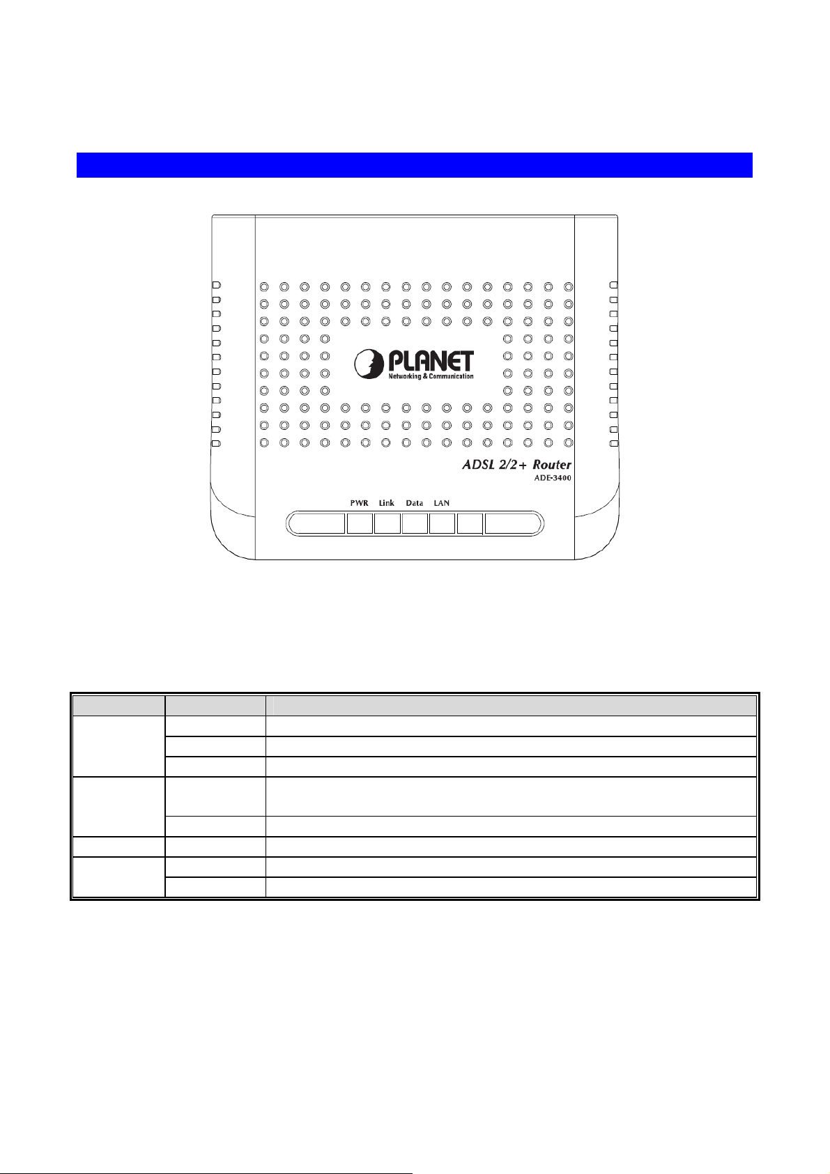
Front Panel of ADE-3400
Front Panel LED definition
LED State Description
ON When the router is powered on and in ready state.
PWR
Link
Data
LAN
Red The devise is being turned on and booting.
OFF When the router is powered off.
ON
Flashing Modem is trying to establish a connection to telecom’s network.
Flashing Data is transferred between Router and Internet.
ON Link
Flashing TX or RX activity.
Successful connection between ADSL modem and telecom's
network.
9
Page 10

Rear Panel of ADE-3400
Rear Panel Port and Button Definition
Connector Description
POWER Button
Power
Reset
Ethernet
Line
The power button is for turn on or turns off the router.
Power connector with 12V DC, 0.5A
The reset button can restore the default settings of device. To restore
factory defaults, keep the device powered on and push a paper clip into
the hole. Press down the button over 5 seconds and then release.
Router is successfully connected to a device through the Ethernet port.
If the LED is flashing, the Router is actively sending or receiving data
over that port.
The RJ-11 connector allows data communication between the modem
and the ADSL network through a twisted-pair phone wire.
10
Page 11
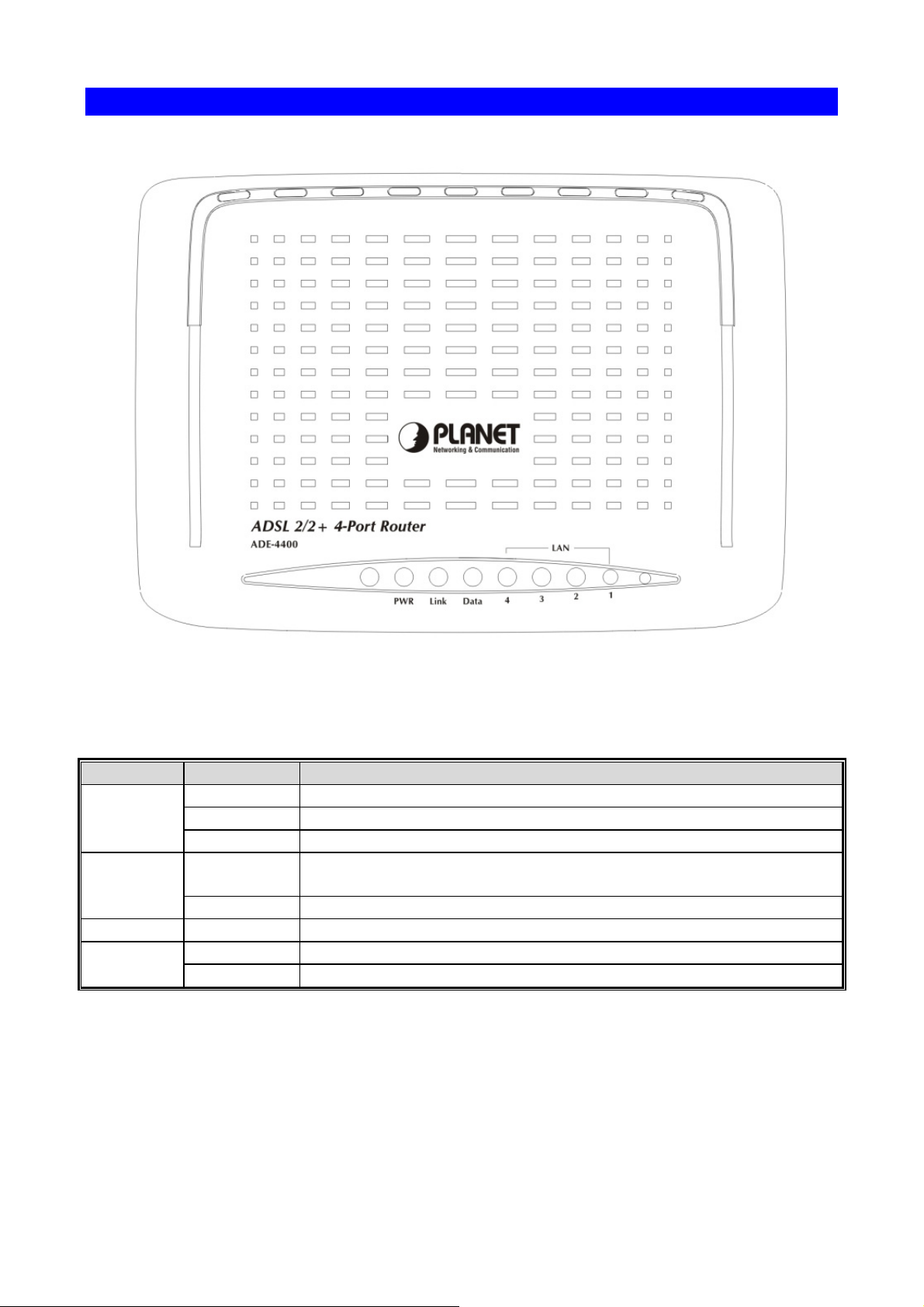
Front Panel of ADE-4400
Front Panel LED definition
LED State Description
Green When the router is powered on and in ready state.
PWR
Red The devise is being turned on and booting.
OFF When the router is powered off.
ON
Successful connection between ADSL modem and telecom's
network. Link
Flashing Modem is trying to establish a connection to telecom’s network.
Data
LAN 1-4
Flashing Data is transferred between Router and Internet.
ON Link
Flashing TX or RX activity
11
Page 12

Rear Panel of ADE-4400
Rear Panel Port and Button Definition
Connector Description
POWER Button
Reset
Power
LAN 1-4
Line
The power button is for turn on or turns off the router.
The reset button can restore the default settings of device. To restore
factory defaults, keep the device powered on and push a paper clip into
the hole. Press down the button over 5 seconds and then release.
Power connector with 12V DC, 0.5A
Router is successfully connected to a device through the corresponding
port (1, 2, 3, or 4). If the LED is flashing, the Router is actively sending or
receiving data over that port.
The RJ-11 connector allows data communication between the modem
and the ADSL network through a twisted-pair phone wire.
12
Page 13
2. Installation
This chapter offers information about installing your router. If you are not familiar with the
hardware or software parameters presented here, please consult your service provider for
the values needed.
2.1 System Requirement
1. Personal computer (PC)
2. Pentium III 266 MHz processor or higher
3. 128 MB RAM minimum
4. 20 MB of free disk space minimum
5. RJ45 Ethernet Port
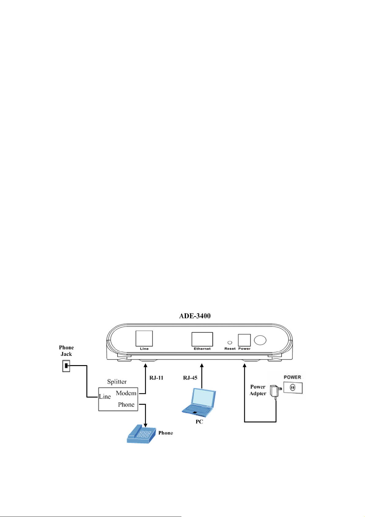
2.2 Hardware Installation
Please connect the device to you computer as follow:
z If connecting to the splitter, connect the “Line” splitter to wall jack using one
telephone cable
z Use another telephone cable to connect “MODEM” port of the splitter and “LINE” port
of the modem. The “Phone” port of the splitter can be use to connect the telephone
by a telephone cable.
z Use Ethernet cable to connect “LAN” port of the modem and “LAN” port of your
computer.
Figure1 ADE-3400 connection diagram
13
Page 14
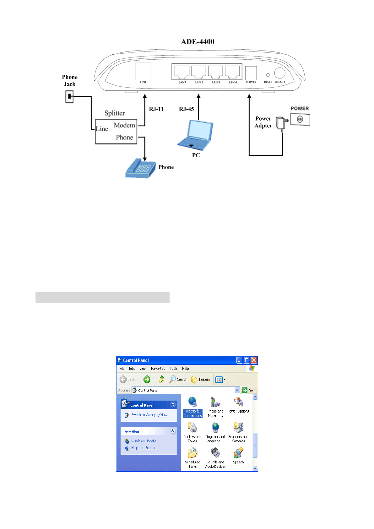
Figure2 ADE-4400 connection diagram
If do not need to connect to the splitter,
z Connect the modem to wall jack with a telephone cable.
z Use Ethernet cable to connect “LAN” port of the modem and network adaptor of your
computer.
2.3 Configuring the Network Properties
Configuring PC in Windows XP
1. Go to Start / Control Panel (in Classic View). In the Control Panel, double-click on
Network Connections
2. Double-click Local Area Connection.
14
Page 15

3. In the Local Area Connection Status window, click Properties.
4. Select Internet Protocol (TCP/IP) and click Properties.
5. Select the Obtain an IP address automatically and the Obtain DNS server address
automatically radio buttons.
15
Page 16
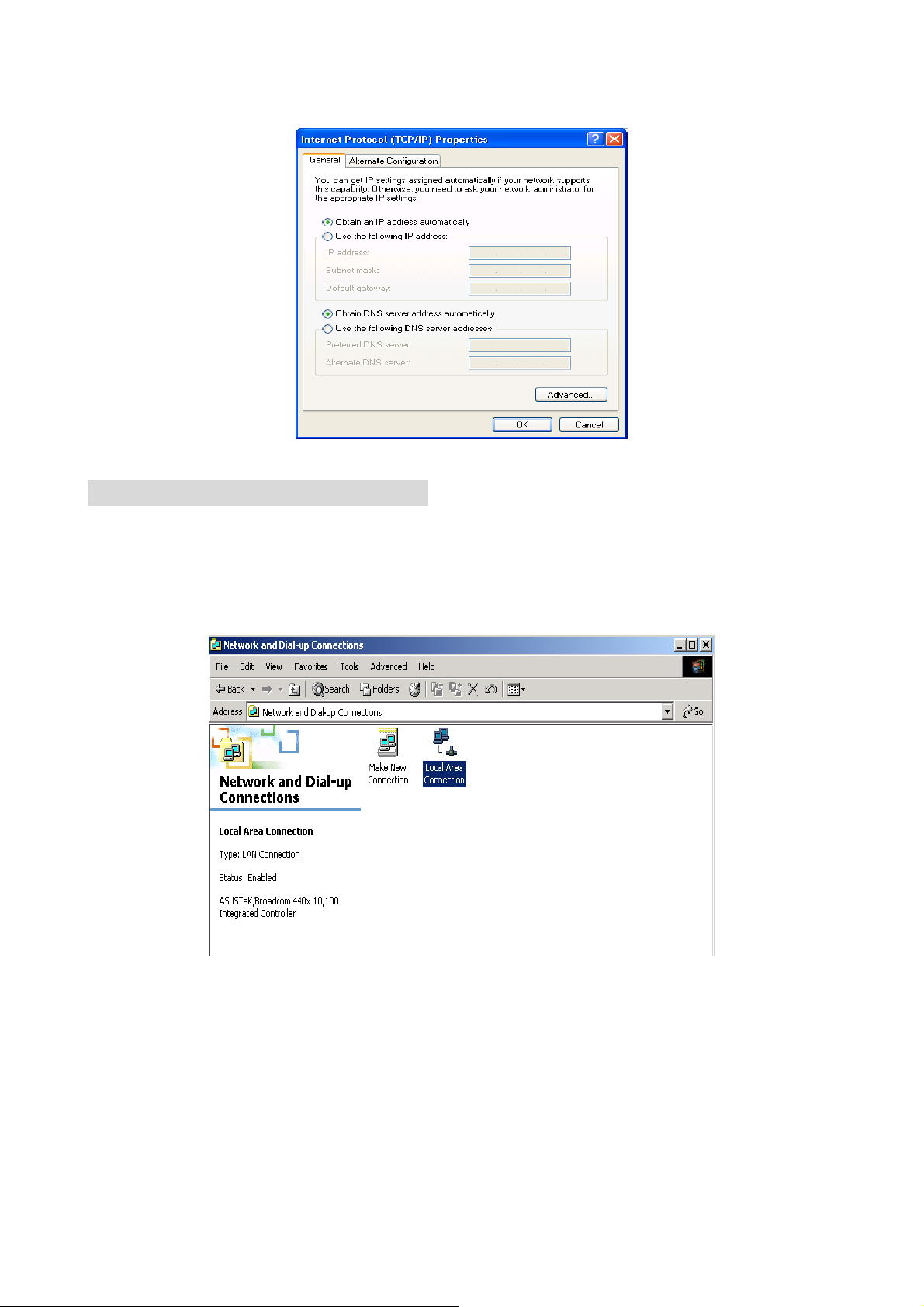
6. Click OK to finish the configuration.
Configuring PC in Windows 2000
1. Go to Start / Settings / Control Panel. In the Control Panel, double-click on Network
and Dial-up Connections.
2. Double-click Local Area Connection.
3. In the Local Area Connection Status window click Properties.
4. Select Internet Protocol (TCP/IP) and click Properties.
16
Page 17
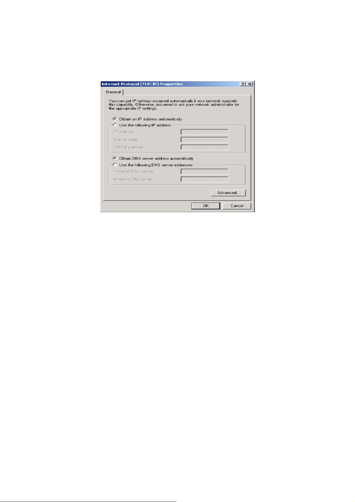
5. Select the Obtain an IP address automatically and the Obtain DNS server address
automatically radio buttons.
6. Click OK to finish the configuration.
17
Page 18
Configuring PC in Windows 98/Me
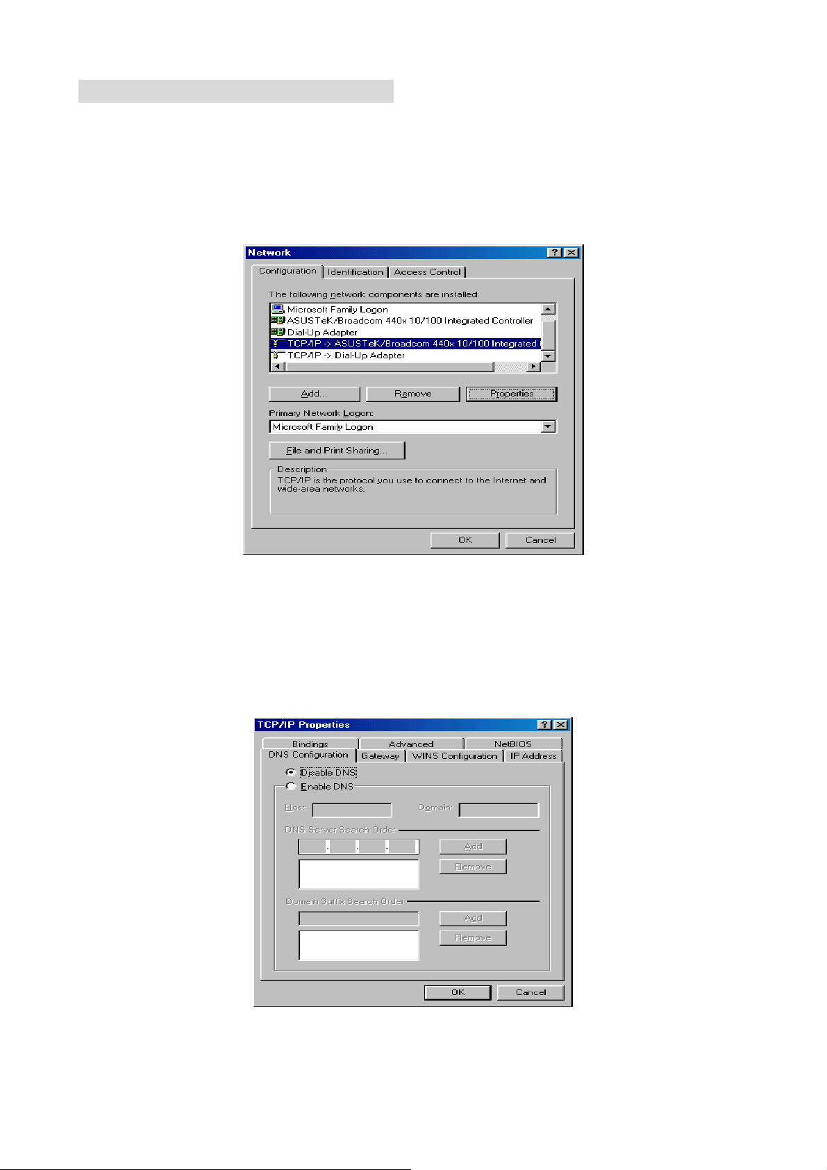
1. Go to Start / Settings / Control Panel. In the Control Panel, double-click on Network
and choose the Configuration tab.
2. Select TCP/IP Æ NE2000 Compatible, or the name of your Network Interface Card
(NIC) in your PC.
3. Select the Obtain an IP address automatically radio button.
4. Then select the DNS Configuration tab.
5. Select the Disable DNS radio button and click OK to finish the configuration.
18
Page 19
3. Web Configuration Management
This chapter describes how to configure the router by using the Web-based configuration
utility.
3.1 Access the Router
The following is the detailed description of accessing the router for the first time.
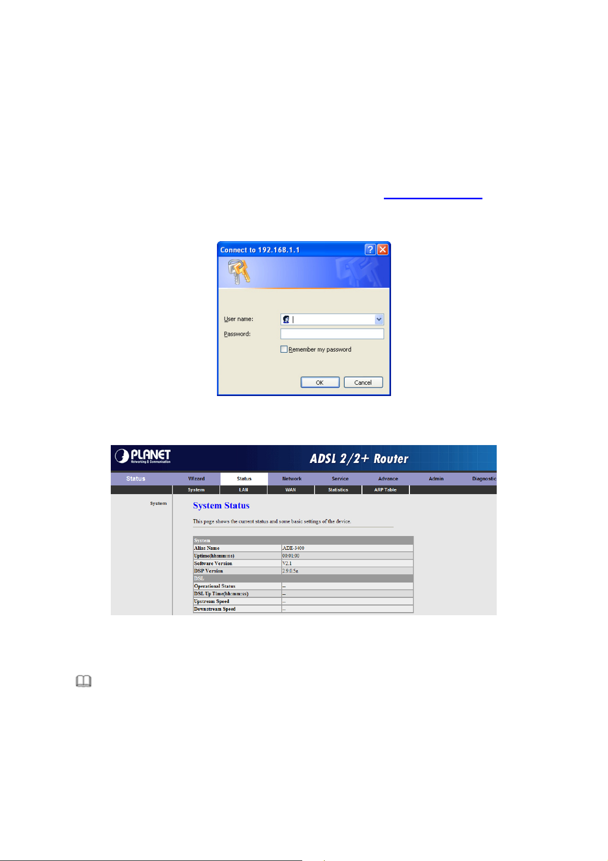
Step 1 : Open the Internet Explorer (IE) browser and enter http://192.168.1.1.
Step 2 : In the Login page that is displayed, enter the username and password.
The username and password of the super user are admin and admin.
The username and password of the common user are user and user.
If you log in as a super user, the page shown in the following figure appears. You can
check, configure and modify all the settings.
If you log in as a common user, you can check the status of the router, but can not
configure the most of the settings.
Note:
In the Web configuration page, you can click Apply Changes to save the settings
temporarily. If you want to save the settings of this page permanently, click save of
Attention that appears at the button of the Web page after the configuration.
19
Page 20

3.2 Wizard
The Wizard page guides fast and accurate configuration of the Internet connection and
other important parameters. The following sections describe these various configuration
parameters. Whether you configure these parameters or use the default ones, click NEXT
to enable your Internet connection.
When subscribing to a broadband service, you should be aware of the method by which
you are connected to the Internet. Your physical WAN device can be either PPP, ADSL, or
both. The technical information about the properties of your Internet connection is
provided by your Internet Service Provider (ISP). For example, your ISP should inform
you whether you are connected to the Internet using a static or dynamic IP address, and
the protocol that you use to communicate on the Internet.
In the navigation bar, click Wizard. The page shown in the following figure appears.
The following table describes the parameters of this page:
Field Description
User Name
New Password
Confirmed Password Enter the new password again.
After finishing the configuration, click NEXT. The page shown in the following figure
appears. In this page, you can configure the system time and Network Time Protocol
(NTP) server.
Choose the user name for accessing the router. You
can choose admin or user.
Enter the password to which you want to change the
old password. The password can not contain space
key, %, “, ? or &.
20
Page 21
The following table describes the parameters of this page:
Field Description
State
You can disable or enable NTP function. You have to enable it if
you want to configure the parameters of this page.
Server IP Enter the IP address of the specified time server manually.
Set the interval that the router obtains the time from the time
Interval
server. That is, the interval that the router verifies the time with
the server.
Time Zone
Choose the time zone in which area you are from the drop down
list.
GMT time It displays the Greenwich Mean Time (GMT).
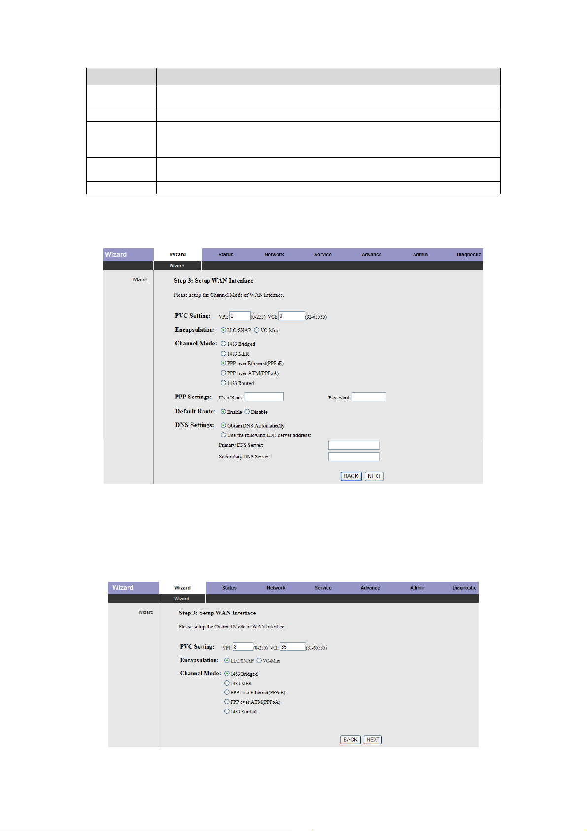
After finishing the configuration, click NEXT. The page shown in the following figure
appears.
There are five channel modes, the following describes them respectively.
1483 Bridged
In the Setup WAN Interface page, enter the correct PVC, set the channel mode to 1483
Bridged.
21
Page 22

Click NEXT, and the page shown in the following figure appears.
If you want to modify the configuration, click BACK to return to the previous page. If you
ensure the configuration is correct, click FINISH to take the configuration effect.
1483 MER
In the Setup WAN Interface page, enter the correct PVC, set the channel mode to 1483
MER.
22
Page 23

The following table describes the parameters of this page:
Field Description
VPI: Virtua
l Path Identifier (VPI) is the virtual path between two
points in an ATM network, ranging from 0 to 255.
PVC Settin
VCI: Virtual Channel Identifier (VCI) is the virtua
two points in an ATM network, ranging from 32 to 65535 (0 to 31 is
reserved for local management of ATM traffic).
Encapsulation
Channel
Mode
select LLC/SNAP or VC-Mux.
Select the WAN connection typ
e. You can select 1483 Bridged, 1483
MER, PPP over Ethernet (PPPoE), PPP over ATM (PPPoA), or 1483
Routed. In this example, 1483 MER is selected.
Default Route You can select Enable or Disable.
end automatically. You need not to enter the IP address.
DNS Settings
Use the following DNS server address: If you want to enter the
DNS server address manually, select it and enter the IP addresses of
primary DNS and secondary DNS.
After finishing the configuration, click NEX . The page shown in the following figure T
appears.
l channel between gs
your ISP. You can Select the method of encapsulation provided by
assigned by the office Obtain DNS Automatically: IP address is
23
Page 24

PPPoE/PPPoA
N Interface page, enter the correct PVC, set the channel mode to In the Setup WA
PPPoE or PPPoA.
The following table describes the parameters of this page:
Field Description
VPI: Virtua
points in an ATM network, ranging from 0 to 255.
PVC Settin
gs
VCI: Virtual Channel Identifier (VCI) is the virtual channel between
two points in an ATM network, ranging from 32 to 65535 (0 to 31 is
reserved for local management of ATM traffic).
Encapsulation
Channel
Mode
PPP Settings
Select the method of encapsulation provided by your ISP. You can
select LLC/SNAP or VC-Mux.
Select the WAN connection type. You can select 1483 Bridged, 1483
MER, PPP over Ethernet (PPPoE), PPP over ATM (PPPoA), or 1483
Routed. In this example, PPPoE is selected.
Enter the username and password for PPP dial-up, which are provided
by your ISP.
Default Route You can select Enable or Disable.
end automatically. You need not to enter the IP address.
DNS Settings
Use the following DNS server address: If you want to enter the
DNS server address manually, select it and enter the IP addresses
of primary DNS and secondary DNS.
l Path Identifier (VPI) is the virtual path between two
fice Obtain DNS Automatically: IP address is assigned by the of
24
Page 25

After finishing the configuration, click NEX . The page shown in the following figure
T
appears.
1483 Routed
In the Setup WAN Interface
Routed.
page, enter the correct PVC, set the channel mode to 1483
25
Page 26

The following table describes the parameters of this page:
Field Description
VPI: Virtual Path Identifier (VPI) is
two points
in an ATM network, and its valid value is from 0 to
the virtual path between
255.
PVC Settings
VCI: Virtual Channel Identifier (VCI) is the virtual channel
betwe
en two points in an ATM network, ranging from 32 to
65535 (0 to 31 is reserved for local management of ATM
traffic).
Encapsulation
Select the method of encapsulation provided by your ISP. You
can select
LLC/SNAP or VC-Mux.
Select the WAN connection type. You can select 1483 Bridged,
Channel Mode
1483 MER, PPP over Ethernet
(PPPoA), or 1483 Routed. In this example, 1483 Routed is
(PPPoE), PPP over ATM
selected.
Obtain an IP address automatically: Obtain the DNS
WAN IP Settings
server a
Use the following IP address: Enter the static IP address
ssigned by the uplink equipment, such as BAS.
provided by your ISP.
Default Route You can select Enable or Disable.
ically: IP address is assigned by the
need not to enter the IP
DNS Settings
Obtain DNS Automat
office end automatically. You
address.
Use the following DNS server address: If you want to enter
the DNS
server address manually, select it and enter the
related data.
After finishing the configuration, click NEX . The page shown in the following figure
T
appears.
26
Page 27

3.3 Status
In the navigatio
LAN, WAN, St
3.3.1System
hoose Status > System. The page that is displayed shows the current status and some
C
basic setting
downstream
n bar, click Status. In the Status page that is displayed contains System,
atistics and ARP Table.
s of the router, such as, uptime, software version, upstream speed,
speed, and other information.
3.3.2 LAN
Choose Status > LAN. The page that is displayed shows some basic LAN settings of the
router. In th
MAC addre
the chapter 03.4.1 LAN.
e LAN Status page, you can view the LAN IP address, DHCP server status,
ss and DHCP client table. If you want to configure the LAN network, refer to
27
Page 28

3.3.3 WAN
Choose Status > WAN. The page that is displayed shows some basic WAN settings of
the router. In the WAN Status page, you can view basic status of WAN, default gateway,
. If you want to configure the WAN network, refer to the chapter 03.4.2 WAN. DNS server
3.3.4 Port Mapping (ADE-4400 only)
Choose Status > Port Mapping. The page that is displayed shows the relationship and
status of port mapping.
3.3.5 Statistics
Choose Status > Statistics. The Statistics page that is displayed contains Traffic
Statistic and DSL Statistic.
3
.3.5.1 Traffic Statistic
lick Traffic Statistic in the lC
is page, you can view the statistics of each network interface.
th
eft pane, the page shown in the following figure appears. In
28
Page 29

3.3.5.2 DSL Statistic
Click DSL Statistic in the left pane, the page shown in the following figure appears. In this
page, you can view the ADSL line statistics, downstream rate, upstream rate and other
information.
3.3.6 ARP Table
Choose Status > ARP Table. In the Arp tables page, you can view the table that shows a
list of learned MAC addresses.
29
Page 30

3.4 Network
In the navigation bar, click Network. The Network page that is displayed contains LAN
and WAN.
3.4.1 LAN
Choose Network > LAN. The LAN page that is displayed contains LAN IP, DHCP, and
DHCP Static IP.
3.4.1.1 LAN IP
Click LAN IP in the left pane, the page show in the following figure appears.
In this page, you can change IP address of the router. The default IP address is
192.168.1.1, whic
The following table describes the parameters of this page:
Field Description
IP Address
Subnet Mask
Secondary IP
h is the private IP address of the router.
Enter the IP address of LAN interface. It is recommended to
use an address from a block that is reserved for private use.
This address block is 192.168.1.1- 192.168.255.254.
Enter the subnet mask of LAN interface. The range of subnet
mask is from 255.255.0.0-255.255.255.254.
Select it to enable the secondary LAN IP address. The two
LAN IP addresses must be in the different network.
n
30
Page 31

3.4.1.2 DHCP
Dyn fig the
amic Host Con
TCP n f this router as a
/IP configuratio
uration Protocol (DHCP) allows the individual PC to obtain
rom the centralized DHCP server. You can configure
DHCP server or disable it. The DHCP server can assign IP address, IP default gateway,
and DNS server to DHCP clients. This router can also act as a surrogate DHCP server
(DHCP proxy) where it relays IP address assignment from an actual real DHCP server to
clients. You can enable or disable DHCP server or DHCP proxy.
Click DHCP in the left pane, the page shown in the following figure appears.
The following table describes the parameters of this page:
Field Description
If set to DHCP Server, the router can assign IP addresses, IP
DHCP Mode
default gateway and DNS Servers to the host in Windows95,
Windows NT and other operation systems that support the
DHCP client.
It specifies the first and the last IP address in the IP address
IP Pool Range
pool. The router assigns IP address that is in the IP pool range
to the host.
Show Client
Click it, the Active DHCP Client Table appears. It shows IP
addresses assigned to clients.
Default Gateway Enter the default gateway of the IP address pool.
Max Lease Time
The lease time determines the period that the host retains the
assigned IP addresses before the IP addresses change.
Enter the domain name if you know. If you leave this blank, the
domain name obtained by DHCP from the ISP is used. You
Domain Name
must enter host name (system name) on each individual PC.
The domain name can be assigned from the router through the
DHCP server.
31
Page 32

Cl ow Client in ode page, the page shown in the following figure
ick Sh the DHCP M
appears. You can view
the IP address assigned to each DHCP client.
The following table describes the parameters and buttons in this page:
Field Description
IP Address
It displays the IP address assigned to the DHCP client from the
router.
It displays the MAC address of the DHCP client.
MAC Address
Each Ethernet device has a unique MAC address. The MAC
address is assigned at the factory and it consists of six pairs of
hexadecimal character, for example, 00-A0-C5-00
-02-12.
It displays the lease time. The lease time determines the period
Expired (s)
that the host retains the assigned IP addresses before the IP
addresses change.
Refresh Click it to refresh this page.
Close Click it to close this page.
In the DHCP Mode field, choose None. The page shown in the following figure appears.
In the DHCP Mode gure
app
ears.
field, choose DHCP Relay. The page shown in the following fi
32
Page 33

The following table describes the parameters and buttons of this page:
Field Description
If set to DHCP Relay, the router acts a
DHCP Mode
surrogate DHCP Server and relays the DHCP
requests and responses between the remote
server and the client.
Relay Server
Enter the DHCP server address provided by
your ISP.
Apply Changes Click it to save the settings of this page.
Undo Click it to refresh this page.
3.4.1.3 DHCP Static IP
Click DHCP Static IP in the left pane, the page shown in the following figure appears. You
can assign the IP addresses on the LAN to the specific individual PCs based on their
MAC address.
The follow le describes s and buttons of this page: ing tab the parameter
Field Description
En ange,
IP Addr
ess
ter the specified IP address in the IP pool r
w
hich is assigned to the host.
Mac Address Enter the MAC address of a host on the LAN.
Af ick it.
Add
Delete
Selected
ter entering the IP address and MAC address, cl
A added in the DHCP Static IP Table.
row will be
Se , then click it,
lect a row in the DHCP Static IP Table
th
is row is deleted.
Undo Click it to refresh this page.
DHCP Static IP Table
It shows the assigned IP address based on the MAC
address.
3.4.2 WAN
Choose Netwo
rk > WAN. The WAN page that is displayed contains WAN, ATM Setting,
and ADSL Setting.
33
Page 34

3.4.2
.1 WAN
Cli e left pane,
ck WAN in th the page shown in the following figure appears.
In this p can config
ure WAN interface of your routeage, you r.
The following table describes the parameters of this page:
Field Description
Default Route Selection You can select Auto or Specified.
VPI
The virtual path between two points in an ATM network,
ranging from 0 to 255.
The virtual channel between two points in an ATM
VCI
network, ranging from 32 to 65535 (1 to 31 are reserved
for known protocols)
Encapsulation You can choose LLC and VC-Mux.
Channel Mode
You can choose 1483 Bridged, 1483 MER, PPPoE,
PPPoA, or 1483 Routed.
Select it to enable Network Address Port Translation
(NAPT) function. If you do not select it and you want to
Enable NAPT
access the Internet normally, you must add a route on the
uplink equipment. Otherwise, the access to the Internet
fails. Normally, it is enabled.
Enabel IGMP
You can enable or disable Internet Group Management
Protocol (IGMP) function.
PPP Settings
User Name
Password
Type
Enter the correct user name for PPP dial-up, which is
provided by your ISP.
Enter the correct password for PPP dial-up, which is
provided by your ISP.
You can choose Continuous, Connect on Demand, or
Manual.
If set the type to Connect on Demand, you need to enter
Idle Time (min)
the idle timeout time. Within the preset minutes, if the
router does not detect the flow of the user continuously,
34
Page 35

Field Description
the router automatically disconnects the PPPoE
connection.
WAN IP Settings
You can choose Fixed IP or DHCP.
If select Fixed IP, you should enter the local IP
Type
address, remote IP address and subnet mask.
If select DHCP, the router is a DHCP client, the WAN
ned by the remote DHCP server.
ce provided by your Enter the IP address of WAN interfa
Local IP Address
IP address is assig
ISP.
Remote IP Address ss provided by your ISP. Enter the gateway IP addre
Netmask Enter the subnet mask of the local IP address.
Unnumbered Select this checkbox to enable IP unnumbered function.
Add
After configuring the parameters of this page, click it to
add a new PVC into the Current ATM VC Table.
Select a PVC in the Current ATM VC Table, and then
Modify
modify the parameters of this PVC. After finishing, click it
to apply the settings of this
PVC.
This table shows the existed PVCs. It shows the interface
Current ATM VC Table
name, channel mode, VPI/VCI, encapsulation mode,
local IP address, r
emote IP address and other
information. The maximum item of this table is eight.
Click it, the PPP Interface-Modify appears. You can
modify the PVCs’ parameters.
in the PPClick PoE mod ge,
you can configure paramete
e, the page shown in the following figure appears. In this pa
rs of this PPPoE PVC.
35
Page 36

The following table describes the parameters and buttons of this page:
Field Description
Protocol
ATM VC C
It displays the protocol type used for this WAN
connection.
The ATM virtual circuit connection assigned for this PPP
interface (VPI/VCI).
Login Name The user name provided by your ISP.
Password The password provided by your ISP.
Authentication
Method
Connection Type
You can choose AUTO, CHAP, or PAP.
You can choose Continuous, Connect on Demand, or
Manual.
If choose Connect on Demand, you need to enter the
Idle Time (s)
idle timeout time. Within the preset minutes, if the router
does not detect the flow of the user continuously, the
router automatically disconnects the PPPoE connection.
Bridge
You can select Bridged Ethernet, Bridged PPPoE, or
Disable Bridge.
AC-Name The accessed equipment type.
Service-Name The service name.
You can select Disable or Enable. After enable it, you
802.1q
need to enter the VLAN ID. The value ranges from 0 to
4095.
Apply Changes Click it to save the ettings of this page temporarily. s
Return Click it to return to the Channel Configuration page.
Undo Click it to refresh this page.
3
.4.2.2 etting ATM S
Click ing in the this
ATM Sett
page, configure rs of the ATM, including QoS, PCR, CDVT, SCR,
you can
and M
BS.
left pane, the page shown in the following figure appears. In
the paramete
36
Page 37

The following table describes the parameters of this page:
Field Description
VPI The virtual path identifier of the ATM PVC.
VCI The virtual channel identifier of the ATM PVC.
QoS
The QoS category of the PVC. You can choose UBR, CBR,
rt-VBR, or nrt-VBR.
Peak cell rate (PCR) is the maximum rate at which cells can be
PCR
transmitted along a connection in the ATM network. Its value
ranges from 1 to 65535.
Cell delay variation tolerance (CDVT) is the amount of delay
CDVT
permitted between ATM cells (in microseconds). Its value ranges
from 0 to 4294967295.
Subtain cell rate (SCR) is the maximum rate that traffic can pass
SCR
over a PVC without the risk of cell loss. Its value ranges from 0 to
65535.
MBS
Maximum burst size (MBS) is the maximum number of cells that
can be transmitted at the PCR. Its value ranges from 0 to 65535.
3.4.2.3 ADSL Setting
Click ADSL Setting in the left pane, the page shown in the following figure appears. In
this page, you can select the DSL modulat n. Mostly, you need to remain this factory
io
default settings. The router supports these modulations: G.L it e, G. D m t , T1.413, ADSL2,
ADSL2+, AnnexL, and AnnexM. The router negotiates the modulation modes with the
DSLAM.
37
Page 38

3.5 Service
In the navigation bar, click Service. In the Service page that is displayed contains DNS,
Firewall, UPNP, IGMP Proxy, TR-069, and ACL.
3.5.1 DNS
Domain Name System (DNS) is an Internet service that translates the domain name into
IP address. Because the domain name is alphabetic, it is easier to remember. The
Internet, however, is based on IP addresses. Every time you use a domain name, DNS
translates the name into the corresponding IP address. For example, the domain name
www.example.com might be translated to 198.105.232.4. The DNS has its own network. If
one DNS server does not know how to translate a particular domain name, it asks another
one, and so on, until the correct IP address is returned.
Choose Service > DNS. The DNS page that is displayed contains DNS and DDNS.
3.5.1.1 DNS
Click DNS in the left pane, the page shown in the following figure appears.
arameters and buttons of this page: The following table describes the p
Field Description
Select it, the route
Attain DNS Automatically
Set DNS Manually
Apply Changes Click it to save the settings of this page.
Reset Selected
assignment from one of the PPPoA, PPPoE or MER
enabled PVC(s) during the connection establishment.
Select it, enter the IP addresses of the primary and
secondary DNS server.
Click it to start configuring the parameters in this
page.
r accepts the first received DNS
38
Page 39

3.5.1.2 DDNS
Click DDNS in the left pane, the page shown in the following figure appears. This page is
used to configure the dynamic DNS address from DynDNS.org or TZO. You can add or
remove to configure dynamic DNS.
The following table describes the parameters of this page:
Field Description
DDNS provider Choose the DDNS provider name.
Hostname The DDNS identifier.
Interface The WAN interface of the router.
Enable Enable or disable DDNS function.
Username The name provided b DDNS provider. y
Password The password provided by DDNS provider.
Email The email provided by DDNS provider.
Key The key provided by DDNS provider.
3.5.2 Firewall
Choose Service > Firewall. The Firewall page that is displayed contains IP Port Filter,
MAC Filter, URL Blocking, Virtual Server, DMZ Setting, and DoS Setting.
39
Page 40

3.5.2.1 IP Port Filter
Click IP Port Filter in the left pane, the page shown in the following figure appears.
Entries in the table are used to restrict certain types of data packets through the gateway.
These filters are helpful in securing or restricting your local network.
3.5.2
.2 MAC Filter
Click r in the ollowing figure appears. Entries
MAC Filt
in th used to ets from your local network to
e table restrict certain types of data pack
Inter the ga al
net through teway. These filters are helpful in securing or restricting your loc
netw
ork.
e left pane, the page shown in the f
are
40
Page 41

3.5.2.3 URL Blocking
Click URL Blocking in the left pane, the page shown in the following figure appears. This
page is used to block a fully qualified domain name, such as tw.yahoo.com and filtered
keyword. You can add or delete FQDN and filtered keyword.
The following table describes the parameters and buttons of this page:
Field Description
You can choose Disable or Enable.
Select Disable to disable URL blocking function and
URL Blocking Capability
keyword filtering function.
Select Enable to block access to the URLs and
keywords specified in the URL Blocking Table.
Keyword Enter the keyword to block.
AddKeyword Click it to add a keyword to the URL Blocking Table.
Delete Selected Keyword
Select a row in the URL Blocking Table and click it to
delete the row.
URL Blocking Table A list of the URL (s) to which access is blocked.
3.5.2.4 Virtual Server
Click Virtual Server in the left pane, the page shown in the following figure appears.
41
Page 42

The following table describes the parameters of this page:
Field Description
You can select the common service type, for example,
AUTH, DNS, or FTP. You can also define a service name.
Service Type
If you select Usual Service Name, the corresponding
parameter has the default settings.
If you select User-defined Service Name, you need to
enter the corresponding parameters.
Protocol
Choose the transport layer protocol that the service type
uses. You can choose TCP or UDP.
WAN Setting You can choose Interface or IP Address.
WAN Interface Choose the router port that uses virtual server.
WAN Port Choose the access port on the WAN.
LAN Open Port Enter the port number of the specified service type.
LAN IP Address
Enter the IP address of the virtual server. It is in the same
network segment with LAN IP address of the router.
3.5.2.5 DMZ Setting
Demilitarized Zone (DMZ) is used to provide Internet services w
ithout sacrificing
unauthorized access to its local private network. Typically, the DMZ host contains devices
accessible to Internet traffic, rvers, SMTP (e-mail)
such as web (HTTP) servers, FTP se
servers and DNS servers.
C llowing figure appears.
lick DMZ Setting in the left pane, the page shown in the fo
The following describes h
S ct Enable DMZ t
tep 1 : Sele o enable this function.
S IP address o
tep 2 : Enter an f the DMZ host.
S s
tep 3 : Click Apply Change to save the settings of this page temporarily.
ow to configure DMZ.
42
Page 43

3
.5.2.6 DoS Setting
Denial-of-Service Attac d to
bring the network to its
Click this
DoS Setting
pag
e, you can pre
k (DoS attack) is a type of attack on a network that is designe
knees by flooding it with useless traffic.
in the left pane, the page shown in the following figure appears. In
vent DoS attacks.
3.5.3 UPNP
Choose Service > UPnP, the page shown in the following figure appears. This page is
used to configure UPnP. The system acts as a daemon after you enable it.
43
Page 44

3.5.4 IGMP Proxy
Choose Service > IGMP Proxy, the page shown in the following figure appears. IGMP
proxy enables the system to issue IGMP host messages on behalf of hosts that the
system discovered through standard IGMP interfaces. The system acts as a proxy for its
hosts after you enable it.
3.5.5 TR-069
Choose Service > TR-069, the page shown in the following page appears. In this page,
you can configure the TR-069 CPE.
44
Page 45

The following table describes the parameters of this page:
Field Description
ACS
URL The URL of the auto-configuration server to connect to.
User Name The user name for logging in to the ACS.
Password The password for logging in to the ACS.
Periodic Inform Enable
Select Enable to periodically connect to the ACS to check
whether the configuration updates.
Periodic Inform Interval Specify the amount of time between connections to ACS.
Connection Request
User Name The connection username provided by TR-069 service.
Password The connection password provided by TR-069 service.
Debug
Show Message
CPE sends GetRPC
Skip MReboot
Delay
Auto-Execution
Select Enable to display ACS SOAP messages on the
serial console.
Select Enable, the router contacts the ACS to obtain
configuration updates.
Specify whether to send an MReboot event code in the
inform message.
Specify whether to start the TR-069 program after a short
delay.
Specify whether to automatically start the TR-069 af r the
te
router is powered on.
3.5.6 ACL
Choose Service > ACL, the page shown in the following figure appears. In this page, you
can permit the data packets from LAN or WAN to access the router. You can configure the
IP address for Access Control List (ACL). If ACL is enabled, only the effective IP address
in the ACL can access the router.
Note:
If you select Enable in ACL capability, ensure that your host IP address is in ACL list
before it takes effect.
45
Page 46

The following table describes the parameters and buttons of this page:
Field Description
Direction Select
Select the router interface. You can select LAN or WAN. In this
example, LAN is selected.
LAN ACL Switch Select it to enable or disable ACL function.
Enter the IP address of the specified interface. Only the IP address
IP Address
that is in the same network segment with the IP address of the
specified interface can access the router.
Services Allowed
Add
You can choose the following services from LAN: web, telnet, ftp,
tftp, snmp, or ping. You can also choose all the services.
After setting the parameters, click it to add an entry to the Current
ACL Table.
Reset Click it to refresh this page.
Set direction of the data packets to WAN, the page shown in the following figure appears.
46
Page 47

The following table describes the parameters and buttons of this page:
Field Description
Direction Select
WAN Setting You can choose Interface or IP Address.
WAN Interface
IP Address
Services Allowed
Add
Reset Click it to refresh this page.
Select the router interface. You can select LAN or WAN.
In this example, WAN is selected.
Choose
WAN to access the router.
Enter the IP address on the WAN. Only the IP address
that is in the same network segment with the IP address
on the WAN can access the router.
You can choose the following services from WAN: web,
telnet, ftp, tftp, snmp, or ping. You can also choose all
the services.
After setting the parameters, click it to add an entry to
the Current ACL Table.
the interface that permits data packets from
3.6 Advance
In the navigation bar, click Advance. In the Advance page that is displayed contains
Bridge Setting, Routing, QoS, SNMP and Others.
3.6.1 Bridge Setting
Choose Advance > Bridge Setting, the page shown in the following figure appears. This
page is used to configure the bridge parameters. You can change the settings or view
some information on the bridge and its attached ports.
The following table d button of this page: escribes the parameters and
Field Description
Aging Time
802.1d Spanning Tree
Show MACs
If the host is idle for 300 seconds (default
value), its entry is deleted from the bridge table.
You can select Disabled or Enabled.
Select Enabled to provide path redundancy
while preventing undesirable loops in your
network.
Click it to show a list of the learned MAC
addresses for the bridge.
47
Page 48

Click Show MACs, the page shown in the following figure appears. This table shows a list
of learned MAC addresses for this bridge.
3.6.2 Routing
Choose Advance > Routing, the page shown in the following figure appears. The page
that is displayed contains RIP and Static Route.
3.6.2.1 Static Route
Click Static Route in the left pane, the page shown in the following figure appears. This
page is used to configure the routing information. You can add or delete IP routes.
48
Page 49

The following table describes the parameters and buttons of this page:
Field Description
Enable Select it to use static IP routes.
Destination Enter the IP address of the destination device.
Subnet Mask Enter the subnet mask of the destination device.
Next Hop
Enter the IP address of the next hop in the IP route to
the destination device.
Metric The metric cost for the destination.
Interface The interface for the specified route.
Add Route
Click it to add the new static route to the Static Route
Table .
Select a row in the Static Route Table and modify the
Update parameters. Then click it to save the settings
temporarily.
Delete Selected
Select a row in the Static Route Table and click it to
delete the row.
Click it, the IP Route Table appears. You can view a list
Show Routes
of destination routes commonly accessed by your
network.
Static Route Table A list of the previously configured static IP routes.
Click Show Routes, the page shown in the following figure appears. The table shows a
list of destination routes commonly accessed by your network.
3.6.2.2 RIP
Click RIP in the left pane, the page shown in
the following figure appears. If you are using
this device as a RIP-enabled router to communicate with others using Routing Information
Protocol (RIP), enable RIP. This page is used to select the interfaces on your devices that
use RIP, and the version of the protocol used.
49
Page 50

The following table describes the parameters and buttons of this page:
Field Description
RIP
Select On, the router communicates with other RIP-enabled
devices.
Apply Click it to save the settings of this page.
Interface Choose the router interface that uses RIP.
Choose the interface version that receives RIP messages. You
can choose RIP1, RIP2, or Both.
Choose RIP1 indicates the router receives RIP v1
Recv Version
messages.
Choose RIP2 indicates the router receives RIP v2
messages.
Choose Both indicates the router receives RIP v1 and RIP
v2 messages.
The working mode for sending RIP messages. You can choose
RIP1 or RIP2.
Send Version
Choose RIP1 indicates the router broadcasts RIP1
messages only.
Choose RIP2 indicates the router multicasts RIP2
messages only.
Add Click it to add the RIP interface to the Rip Config List.
Delete
Select a row in the Rip Config List and click it to delete the
row.
3.6.3 Port Mapping (ADE-4400 only)
Choose Advance > QoS, the page shown in the following figure appears.
50
Page 51

3.6.4 Q
Choo > QoS . Entries in the QoS used ket based on
physi CP/U
oS
se Advance , the page shown in the following figure appears
Rule List are
cal LAN port, T
to assign the precedence for each incoming pac
DP port number, source IP address, destination IP address and
other information.
d click ApStep 1 : Enable IP QoS an ply to enable IP QoS function.
Step 2 : Click add rule to add a new IP QoS rule.
The page shown in the following figure appears.
51
Page 52

The following table describes the parameters and buttons of this page:
Field Description
IP Q
oS
Select to enable or disable IP QoS function. You need to enable IP
Q rs of this page.
oS if you want to configure the paramete
QoS Y d, or DSCP based. Policy ou can choose stream based, 802.1p base
Schedule Mode You can choose strict prior or WFQ (4:3:2:1).
Src IP T acket. he IP address of the source data p
Src Mask The subnet mask of the source IP address.
Des f the destination data packet. t IP The IP address o
Dest Mask The subnet mask of the destination IP address.
Src Port The port of the s ource data packet.
Dest Port The port of the destination data packet.
Protocol
The protocol responds to the ,
U
DP, or ICMP.
IP QoS rules. You can choose TCP
Phy Port The LAN interface responds to the IP QoS rules.
Set
priority
IP Precedence
IP T
oS
The priority of the IP QoS rules. P0 is the highest priority and P3
the lowest.
You can choose from 0 to 7 define the priority in the ToS of the I
dat
packet. a
T
he type of IP ToS for classifying the data package
Y ize
ou can choose Normal Service, Minimize Cost, Maxim
is
Reliability, Maximize Throughput, or Minimize Delay.
802.1p You can choose from 0 to 7.
delete Select a row in the QoS rule list and click it to delete the row.
delete all Select all the rows in the QoS rule list and click it to delete the rows.
P
3.6.5 SNMP
Choose Advance > SNMP, the page shown in the following figure appears. You can
configure the SNMP parameters.
52
Page 53

The following table describes the parameters of this page:
Field Description
Select it to enable SNMP function. You need to enable
Enable SNMP
Trap IP Address
Community name
(read-only)
Community name
(write-only)
3.6.6 Others
Choose Advance > Others, the page shown in the following figure appears.
SNMP, and then you can configure the parameters of
this page.
Enter the trap IP address. The trap information is sent
to the corresponding host.
The network administrators must use this password to
read the information of this router.
The network administrators must use this password to
configure the information of the router.
3.7 Admin
In the navigation bar, click Admin. The Admin page that is displayed contains
Commit/Reboot, Upgrade, System Log, Password and Time Zone.
3.7.1 Commit/Reboot
Choose Admin > Commit/Reboot, the page shown in the following figure appears. You
can set the router reset to the default settings or set the router to commit the current
settings.
53
Page 54

The following table describes the parameters and button of this page:
ield DescriptiF on
You can choose Save Current Configuration or Factory
Default Configuration.
Reboot from
Save Current Configuration: Reset to the factory
default settings, and then reboot the rout
a Factory Default Configuration: S
settings, and then reboot the router.
Reboot Click it to reboot the router.
3.7.2 Upgrade
er.
ve the current
Choose A
Firmware
dmin > contains Upgrade
and Bac
Upgrade. The Upgrade page that is displayed
. kup/Restore
Caution:
Do no
progre
t turn off
ss.
the router or press the Reset button while the procedure is in
3.7.2.1 Upgrade Firmware
Click Upgrade Firmware in the left pane, the page shown in the following figure appears.
, you can upgrade the firmware of the router. In this page
The following table describes the parameters and button of this page:
Field Description
Select File Click Browse to select the firmware file.
Upload
After selecting the firmware file, click Upload to starting
upgrading the firmware file.
Reset Click it to starting selecting the firmware file.
54
Page 55

3
.7.2.2 Backup/Restore
Click p/Restore in ears.
Backu the left pane, the page shown in the following figure app
You c urren t was
save
d previously.
t settings to a file and restore the settings from the file thaan backup the c
The following table describes the parameters and button of this page:
Field Description
Save Settings to File
Click it, and select the path. Then you can sav
configuration file of the router.
e the
Load Settings from File Click Browse to select the configuration file.
After selecting the configuration file of the router,
Upload
click Upload to start uploading the configuration
file of the router.
3.7.3 System Log
Choose Admin > System Log, the page shown in the following figure appears. In this
page, you can enable or disable system log function and view the system log.
55
Page 56

3
.7.4 Password
Choo > Pass fault,
se Admin word, the page shown in the following figure appears. By de
the user name and pa user
name and password ar
ssword are admin and admin respectively. The common
e user and user respectively.
The fo e describes the parameters of this page: llowing tabl
Field Description
U
ser Name
New Password
Choose the user name for accessing the router. You can
choose admin or user.
Enter the password to which you want to change the old
password.
Confirmed Password Enter the new password again.
Set to Default Password Select it, the password is set to the default password.
3.7.5 Time Zone
Choose Admin > Time Zone, the page shown in the following figure appears. You can
configure the system time manually or get the system time from the time server.
56
Page 57

The following table describes the parameters of this page:
Field Description
System Time Set the system time manually.
NTP Configuration
State
Server Set the primary NTP server manually.
Server2 Set the secondary NTP server manually.
Time Zone
3
.8 Diagnostic
Select enable or disable NTP function. You need to enable
NTP if you want to configure the parameters of NTP.
Choose the time zone in which area you are from the drop
down list.
In the iag ntains
Ping, A an
3.8.1 Ping
navigation bar, click D
TM Loopback, ADSL
Choose Diagnostic > Ping. The page shown in the following figure appears.
The following table describes the parameter and button of this page:
Field Description
Host Enter the valid IP address or domain name.
PING Click it to start to Ping.
nostic. The Diagnostic page that is displayed co
d Diagnostic Test.
3.8.2 ATM Loopback
Choose Diagnostic > ATM Loopback. The page shown in the following figure appears.
In this page, you can use VCC loopback function to check the connectivity of the VCC.
The ATM loopback test is useful for troubleshooting problems with the DSLAM and ATM
network.
57
Page 58

Click Go! to start testing.
3.8.3 ADSL
Choose Diag L. The page shown in the following figure appears. It is used
for ADSL tone diagnos
nostic > ADS
tics.
Click Start to start ADSL tone diagnostics.
3.8.4 Diagnostic Test
Choose Diagnostic > Diagnostic Test, the page shown in the following figure appears.
In this page, you can test the DSL connection. You can also view the LAN status
connection and ADSL connection.
Click Run Diagnostic Test to start testing.
58
Page 59

Appendix A: Glossary
Addres
A bit ma ect bits fr 2 bits
long an the ne
and one s of
AAL5
ATM Adaptation Layer - This layer maps higher layer user data into ATM cells, making the
data suitable for trans
ADSL
symmetric digital subscriber line A
ATM
A annel
synchronous Transfer Mode - A cell-based data transfer technique in which ch
demand determines packet allocation. ATM offers fast packet technology,
real time, and demand led switching for efficient use of network resources.
AWG
s mask
sk sel om an Internet address for subnet addressing. The mask is 3
d selects twork portion of the Internet address
or more bit the local portion. Sometimes it called subnet mask.
port through the ATM network.
American Wire Gauge - The measurement of thickness of a wire
Bridge
A device connects two or more physical networks and forward packets between them.
B rtain traffic. Related
ridges can usually be made to filter packets, that is, to forward only ce
devices are rep which d electrical signals from one cable to the other
and full-fledged rs whic riteria.
Broadband
Characteristic of any network multiplexes independent network carriers onto a single cable.
Broadband technology allows sev
o
ne network does not interfere with traffic from another. Broadcast a packet delivery system
w
here a copy of a given packet is given to all hosts attached to the network. Example:
E
thernet.
CO
eaters simply forwar
route h make routing decisions based on several c
eral networks to coexist on one single cable; traffic from
Central Office. Refers to equipment located at a Telco or service provider's office.
CPE
Customer Premises Equipment located in a user's premises
59
Page 60

DHCP (Dynamic Host Configuration Protocol)
DHCP is software that automatically assigns IP addresses to client stations logging onto a
TCP/IP network. DHCP eliminates having to manually assign permanent IP addresses to
every device on your network. DHCP software typically runs in servers and is also found in
network devices such as Routers.
DMT
Discrete Multi-Tone frequency signal modulation
Downstream rate
The line rate for return messages or data transfers from the network machine to the user's
premises machine.
DSLAM
D
igital Subscriber Line Access Multiplex
D
ynamic IP Addresses
A dynamic IP address is an IP address that is automatically assigned to a client station
(computer, printer, etc.) in a TCP/IP network. Dynamic IP addresses are typically assigned
by a DHCP server, which can be a computer on the network or another piece of hardware,
such as the Router. A dynamic IP address
may change every time your computer connects to the network.
Encapsulation
The technique layer protocols in which a layer adds header information to the protocol data
unit (PDU) from the layer above. As an example, in Internet terminology, a packet would
contain a header from the physical layer, followed by a header from the network layer (IP),
followed by a header from the transport
la rotocol data.
yer (TCP), and followed by the application p
E
thernet
O
ne of the most common local area network (LAN) wiring schemes, Ethernet has a
tr
ansmission rate of 10 Mbps.
FTP
File Transfer Protocol. The Internet protocol (and program) transfer files between hosts.
Hop count
A the Internet. It is equivalent to the number of
measure of distance between two points on
ateways that separate the source and destination.
g
60
Page 61

HTML
Hypertext Markup Language - The page-coding language for the World Wide Web.
HTML browser
A browser used to traverse the Internet, such as Netscape or
Microsoft Internet Explorer.
ttp
h
Hyperte
xt Transfer Protocol - The protocol carry world-wide-web (www) traffic between a
www browser computer and the www server being accessed.
MP
IC
Interne
the IP layer. ICMP is actually part o
t Control Message Protocol - The protocol handle errors and control messages at
f the IP protocol.
Intern
et address
An IP address is assigned in blocks of numbers to user organizations accessing the
Internet. These addresses are established by the United States Departmen
of Defense's Network Information Center. Duplicate addresses can cause m
on the
addresses responsibly. Each address is a 32-bit address in the for
network, but the NIC trusts organizations to use individual
m of x.x.x.x where x is an
t
ajor problems
ight- bit number from 0 to 255. There are three classes: A, B and C, depending on how
e
many co
mputers on the site are likely to be connected.
Internet Protocol (IP)
The network layer protocol for the Internet protocol suite
address
IP
The 32-bit ad
dress assigned to hosts that want to participate in a TCP/IP Internet.
ISP
Internet service provider - A company allows home and corporate users to connect to the
Internet.
AC
M
ia Access Control Layer - A sub-layer of the Data Link Layer (Layer 2) of the ISO OSI
Med
Model responsible for media control.
61
Page 62

MIB
Management Information Base - A collection of objects can be accessed via a network
management protocol, such as SNMP and CMIP (Common Management Information
Protocol).
NAT
Netwo
rk Address Translation - A proposal for IP address reuse, where the local IP address
is mapped to a globally unique address.
NVT
Network Virtual Terminal
PAP
assword Authentication Protocol
P
PORT
The abstraction used in In
ternet transport protocols to distinguish among multiple
simultaneous connections to a single destination host.
POTS
Plain Old Telephone Service - This is the ter
m describe basic telephone service.
PP
P
Point-to-Point-Pr
otocol - The successor to SLIP, PPP provides router-to-router and
host-to-network connections over both synchronous and asynchronous circuits.
PPPoE
PPP over Ethernet is a protocol for conne
cting remote hosts to the Internet over an
always-on connection by simulating a dial-up connection.
Remote s
erver
A network computer allows a user to log on to the network from a distant location.
FC
R
est for Comments - Refers to documents published by the Internet Engineering Task
Requ
Force (IETF) proposing standard protocols and procedures for the Internet. RFC can be
und at www.ietf.org.
fo
62
Page 63

Route
The path that network traffic takes from its source to its destination. The route a data
m
ay follow can include many gateways and many physical networks.
In the Internet, ea
ch datagram is routed separately.
gram
R
outer
A sys
tem is responsible for making decisions about which of several paths network (or
Internet) traffic will follow. To do this, it uses a routing protocol to gain information about th
network and algorithms to choose the best route based on sev
"r
outing metrics".
eral criteria known as
Routing Table
Information stored within a router that contains netwo
sed to select the most appropriate route to forward information along.
u
rk path and status information. It is
Routing Information Protocol
Routers periodically exchange information with one another so that they can d
etermine
minimum distance paths between sources and destinations.
e
SNMP
Simple Network Management Protocol - The network management protocol of choice for
TCP/IP-based Internet.
SOCKET
(1) The Berkeley UNIX mechanism for creating a virtual c
) IBM term for software interfaces that allow two UNIX application programs to talk via
(2
TCP/IP proto
cols.
onnection between processes.
panning-Tree Bridge Protocol (STP)
S
ning-Tree Bridge Protocol (STP) - Part of an IEEE standard. A mechanism for
Span
detecting and preventing loops from occurring in a multi-bridged environment.
When thre
f a bridge forwards all packets that are not recognized as being local,
o
some
e or more LAN's segments are connected via bridges, a loop can occur. Because
packets can circulate for long periods of time, eventually degrading system
performance. This algorithm ensures only one path connects any pair of stations, selecting
one bridge as the 'root' bridge, with th
paths should radiate.
e highest priority one as identifier, from which all
63
Page 64

Spoo
fing
A method of fooling network end stations into believing that keep alive signals have com
e
from and returned to the host. Polls are received and returned locally at
either end
Static
IP Address
A static IP address is an IP address permanently assigned to computer in a TCP/IP network.
Static IP addresses are usually assigned
a
ccessed by multiple users, such as Server PCs, or printers. If you are using your Router to
your cable or DSL Internet connection, contact your ISP to see if they have assigned
share
your home a static IP addr
config
uration.
ess. You will need that address during your Router's
to networked devices that are consistently
ubnet
S
For rou
ting purposes, IP networks can be divided into logical subnets by using a subnet
mask. Values below those of the mask are valid addresses on the subnet.
CP
T
Transm
ission Control Protocol - The major transport protocol in the Internet suite of
protocols provides reliable, connection-oriented full-duplex streams.
TFTP
Trivial File Transfer Protocol. A simple file transfer protocol (a simplified version of F
that is often boot diskless workstations and other network devices such as router
etwork (typically a LAN).
n
s over a
Telnet
The virtual terminal protocol in the Internet suite of protocols - Allows users of one ho
log into a remote host and act as normal terminal users of
that host.
Transparent brid
ging
The intelligence necessary to make relaying decisions exists in the bridge itself and
transparent to the communicati
workstation addresses, and ensur
Spann
ing-Tree algorithm).
ng workstations. It involves frame forwarding, learning
ing no topology loops exist (in conjunction with the
TP)
st to
is thus
64
Page 65

UDP
User Datagram Protocol - A connectionless transport protocol that runs on top of TCP/IP's
IP. UDP, like TCP, uses IP for delivery; however, unlike TCP, UDP pro
of datagram without acknowledgments or guaranteed
dependent requests, such as requesting a MIB value from an SNMP agent, in which first
in
setting u
p a connection would take more time than sending the data.
delivery. Best suited for small,
vides for exchange
UNI signaling
User Network Interface signaling for ATM communications.
irtual Connection (VC)
V
A link that seem
s and behaves like a dedicated point-to-point line or a system that delivers
packets in sequence, as happens on an actual point-to-point network. In reality, the data
delivered across a network via the most appropriate route. The sending
evices do not have to be aware of the options and the route is chosen only when a
d
message is sent. There is no pre
-arrangement, so each virtual connection exists only for
and receiving
the duration of that one transmission.
AN
W
is
Wide ar
ea network - A data communications network that spans any distance and is usually
provided by a public carrier (such as a telephone company or service provider).
65
Page 66

Importan
t Note
According to Annex3 of the ERC/REC 70-03 publication, the use of Wideb
Transmissio
F
requency range: 2400-2483.5MHz
Country Restri
France Outdoor use limited to 10 mW
Italy If used outside of own premises, general authorization is
Luxembourg None General authorization required for network and service
Norway Implemented This subsection does not apply for the geographical area
Russia
n Only for indoor applications
n systems has the following National Restrictions:
ction Reason/Remark
Military Radiolocation use. Refarming of the 2.4 GH
e.i.r.p. within the band
2454-2483.5 MHz
has been ongoing in recent years to allow current relaxed
regulation. Full implementation planned 2012
required
supply(not for spectrum)
within a radius of 20km from the centre of Ny-Alesund
and Data
z band
Federation
66
Page 67

EC Declaration of Conformity
For the following equipment:
*Type of Product :
*Model Number : ADE-3400A / ADE-3400B
* Produced by:
Manufacturer‘s Name : Planet T echnology Corp.
Manufacturer‘s Address : 9F, No. 96, Min Chuan Road, Hsin Tien,
is herewith confirmed to comply with the requirements set out in the Council Directive on the
Approximation of the Laws of the Member States relating to
For the evaluation regarding the R&TTE the following standards were applied:
ADSL 2/2+ Router
Taipei, Taiwan, R.O.C.
1999/5/EC R&TTE.
Emission EN 55022 (1998)
Harmonic EN 61000-3-2 (2000)
Flicker EN 61000-3-3 (1995 + A1)
Immunity EN 55024 (2003 + A2)
ESD IEC 61000-4-2 (1995 + A2)
RS IEC 61000-4-3 (1995 + A1)
EFT/ Burst IEC 61000-4-4 (1995 + A2)
Surge IEC 61000-4-5 (1995 + A1)
CS IEC 61000-4-6 (1996 + A1)
Voltage Disp IEC 61000-4-11 (1994 + A1)
LVD EN 60950 (2001)
Responsible for marking this declarati o n i f the:
⌧
Manufacturer Authorized representative established within the EU
Authorized representative established within the EU (if applicable):
Company Name: Planet Technology Corp.
Company Address: 9F, No.96, Min Chuan Road, Hsin Tien, Taipei, Taiwan, R.O.C
Person responsible for making this declaration
Name, Surname Allen Huang
Position / Title : Product Manager
Taiwan
Place Date Legal Signature
07, December, 2007
PLANET TECHNOLOGY CORPORATION
e-mail: sales@planet.com.tw http://www.planet.com.tw
11F, No. 96, Min Chuan Road, Hsin Tien, Taipei, Taiwan, R.O.C. Tel:886-2-2219-9518 Fax:886-2-2219-9528
Page 68

EC Declaration of Conformity
For the following equipment:
*Type of Product :
*Model Number : ADE-4400A / ADE-4400B
* Produced by:
Manufacturer‘s Name : Planet Technology Corp.
Manufacturer‘s Address : 9F, No. 96, Min Chuan Road, Hsin Tien
is herewith confirmed to comply with the requirements set out in the Council Directive on the
Approximation of the Laws of the Member States relating to
For the evaluation regarding the R&TTE the following standards were applied:
ADSL 2/2+ 4-Port Router
Taipei, Taiwan , R. O.C.
1999/5/EC R&TTE.
EN 300 386V1.3.1 (2001)
Emission EN 55022 (1998 Class B)
Harmonic EN 61000-3-2 (2000)
Flicker EN 61000-3-3 (1995 + A1:2001)
Immunity EN 55024
ESD IEC 61000-4-2 (1995 + A1:1998)
RS IEC 61000-4-3 (1996 + A1:1998)
EFT/ Burst IEC 61000-4-4 (1995)
Surge IEC 61000-4-5 (1995)
CS IEC 61000-4-6 (1996)
Voltage Disp IEC 61000-4-11 (1994)
LVD EN 60950 (2000)
Responsible for marking this declarati o n i f the:
⌧
Manufacturer Authorized representative established within the EU
Authorized representative established within the EU (if applicable):
Company Name: Planet Technology Corp.
Company Address: 9F, No.96, Min Chuan Road, Hsin Tien, Taipei, Taiwan, R.O.C
Person responsible for making this declaration
Name, Surname Allen Huang
Position / Title : Product Manager
Taiwan
Place Date Legal Signature
07, December, 2007
PLANET TECHNOLOGY CORPORATION
e-mail: sales@planet.com.tw http://www.planet.com.tw
11F, No. 96, Min Chuan Road, Hsin Tien, Taipei, Taiwan, R.O.C. Tel:886-2-2219-9518 Fax:886-2-2219-9528
 Loading...