

Page 1
Planet•
T5
2.4GHZ DIGITAL
REMOTE CONTROL SYSTEM
Instruction Manual
Includes*
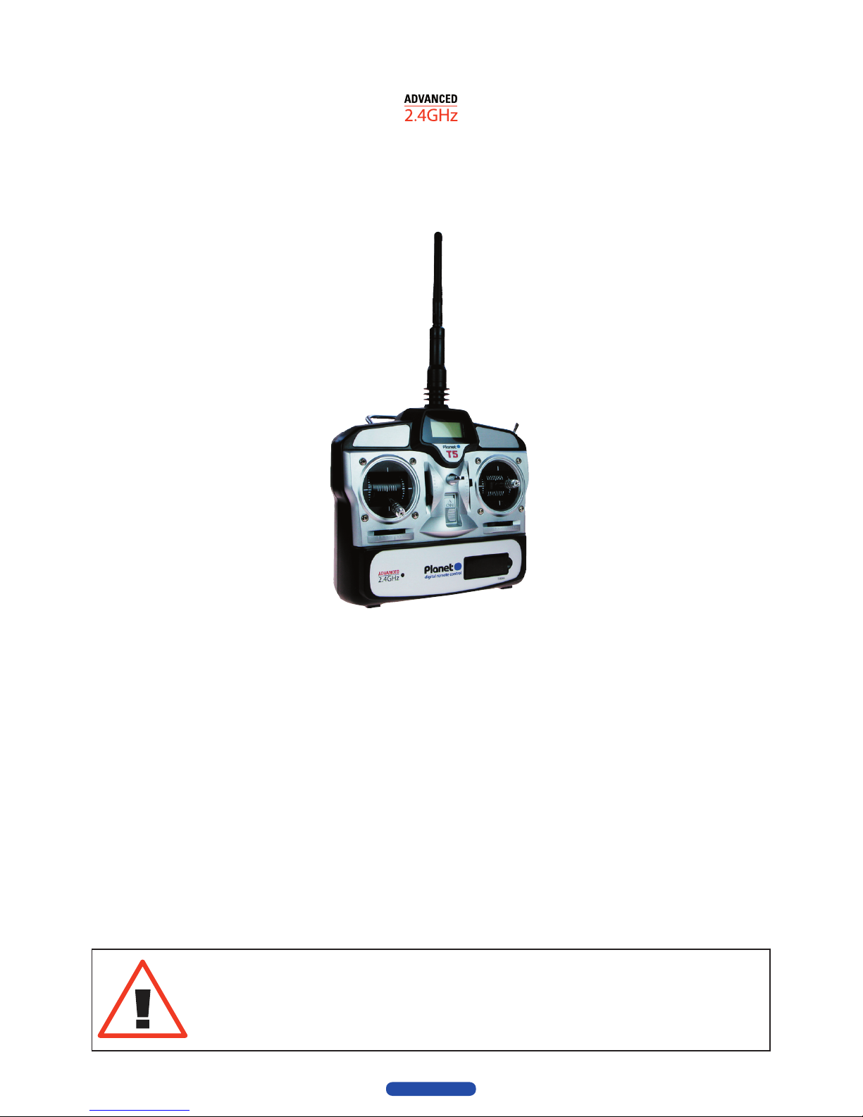
Advanced 2.4GHz 5-channel professional transmitter
Advanced 2.4GHz micro 6-channel receiver
Features
■ Simple one-button transmitter/receiver binding
■ Side & rear ergonomic grips for maximum transmitter security
■ Steel carry handle and neck strap mount
■ Precision, adjustable height dual-axis stick units
■ Front-mounted reversing switch panel
■ Unique slow-rate retract/flap switch (channel 5)
■ Low power consumption 4-cell transmitter
■ Lightweight (6 gram) micro 6-channel receiver
■ Convenient crystal-free operation
*See box label for detailed contents listing
For use with Park Flyer, indoor aircraft
and small electric coaxial helicopter type models.
For use with recreational radio controlled model aircraft only.
Not a toy—suitable only for persons aged 14+.
rock-solid r/c
Planet•
Page 2
WARNING!
Model aircraft flying is a potentially hazardous sport
which has the potential to endanger life, cause injury
or damage property.
When you see this symbol in this manual, your
attention is being drawn to a potential hazard and you
should take particular note.
WARRANTY CONDITIONS
For a period of one year from time of purchase, J. Perkins
Distribution Ltd will repair or replace, at it’s discretion, any
items showing manufacturing or assembly defects that has
been found faulty by our service department. This does not
affect your statutory rights.
J Perkins Distribution Ltd does not accept any liability for any
injury, damage or consequential damage arising as a result
of failure to observe the procedures and precautions outlined
in this manual. J Perkins Distribution Ltd does not accept any
liability that may arise from any misuse or modification of this
equipment, Please note that, whilst every effort is made to
ensure the accuracy of instructions and materials included
with this product, mistakes can occur and neither J. Perkins
Distribution Ltd nor it’s distributors will be held liable for any
loss or damage arising from the use of this system or for any
loss or damage arising from omissions or inaccuracies in the
associated instructions, references, web sites or materials
included or referred to with this product.
We reserve the right to modify the design of this product, the
box contents and manual without prior notification. E&OE
© 2009 J Perkins Distribution Ltd. All rights reserved.
web: www.jperkinsdistribution.co.uk
EU REGULATIONS
J Perkins Distribution Ltd declares that this remote control
system is in compliance with the essential requirements and
other relevant provisions of Directive 1999/5/EC on Radio
equipment and Telecommunications Terminal Equipment. A
copy of the declaration(s) of conformity can be obtained from
J Perkins Distribution Ltd, Ashford rd, Lenham, Kent. UK ME17
2DL. This system complies with the EU directive on Waste
Electrical and Electronic Equipment. Do not dispose of this
product in household waste. At the end of the products’ life,
dispose of it at a designated collection point for the recycling
of waste electrical and electronic equipment.
Please contact your supplier for any advice required on
disposal.
Contents
Warranty conditions ............................................ii
EU regulations .......................................................ii
Introduction ...........................................................1
Safety information ................................................ 1
UK Air Law, BMFA & safety ................................
1
New to Radio Control? ........................................ 1
Not what you expected? ..................................... 1
Transmitter features ............................................. 2
Control trims ...................................................... 2
Channel 5 switch .............................................. 2
Battery status LCD ........................................... 2
Reversing switches .........................................2
Battery fitting ....................................................
3
Charging socket ...............................................3
Trainer/Simulator lead socket ........................
3
Stick tension adjustment ................................4
Stick height adjustment ..................................4
R6M receiver ......................................................... 5
R6M deployment ..............................................5
Receiver connections .....................................5
R6M Specifications ..........................................
6
Servos ..................................................................... 6
Battery and switch ............................................... 6
Binding transmitter to receiver .........................6
Transmitter usage .................................................
7
Tran
smitter aerial positioning ........................7
Range and power check ................................. 7
Battery status LCD ........................................... 8
Mode change switch ....................................... 8
Failsafe ............................................................... 8
Throttle left (mode 2) layout ...........................9
Throttle right (Mode 1) ....................................9
Flight controls - Examples ................................ 10
Helicopter Mode 2 .........................................10
Aircraft mode 2 ............................................... 11
Helicopter mode 1 .......................................... 12
Aircraft mode 1 ............................................... 13
Page 3

T5
Instruction Manual
1
INTRODUCTION
Thank you for purchasing an Advanced 2.4GHz Planet
T5 radio control system. It is designed for remotely
operating small or indoor R/C model aircraft safely
in the easiest possible manner without the need for
crystals.
It’s uncomplicated yet sophisticated design makes it an
ideal first system or a general purpose sport system for
R/C modelling.
It uses state-of-the-art computer technology to bind it’s
transmitter and receiver in such a fashion that, under
most model flying conditions, interference that would
normally cause loss of control in 35mHz or 27mHz
equipment is nearly always rejected—and in most
cases radio functionality is entirely unaffected. This
makes for a safer, more reassuring flying experience.
It also enables a pilot to turn up, switch on and
fly under most conditions—subject to local flying
guidelines and rules.
The new design single aerial micro receiver is
utra-compact and allows for rapid and convenient
installation especially when compared with some twinunit multi-aerial receiver designs.
NB. The Planet T5 is not a complete system; other parts
must be purchased in order to obtain full functionality
from this equipment.
Please read all instructions carefully before using your
Advanced 2.4GHz Planet T5 radio control system.
SAFETY INFORMATION
WARNING!
This equipment must be assembled carefully
into an appropriate R/C aircraft according to the
manufacturers’ recommendations.
Note that Planet T5 is not a ‘full range’ system and
must only be used with small Park Flyer/coaxial
helicopter type R/C models operated at relatively short
range (around 150 metres).
This product is a sophisticated control system for
model aircraft and is not a toy. Suitable only for
persons aged 14+
Check all radio equipment carefully before use and
range check before every flight.
Never fly near people, animals, buildings, power lines,
water or trees.
Ensure that all batteries are either fresh (if alkaline) or
charged (if rechargeable) before using this equipment.
Observe BMFA safety codes at all times when
operating radio controlled models
This equipment is designed to be installed and used
only within a radio control hobby environment.
2.4GHz signals are less tolerant of obstacles so never
fly close to structures, trees, hedges which if flown
behind may cause a temporary loss of signal.
Never fly in rain.
UK AIR LAW, BMFA &
SAFETY
All model aircraft operated in the UK are subject
to UK Air Law. It should be noted that in the UK a
considerable burden of responsibility and a strict duty
of care lie with the pilot of any model aircraft. Under
UK Air Law the pilot assumes all responsibility for his
aircraft.
Radio control model aircraft are potentially capable
of inflicting severe personal injury or even death to
people or animals and can cause considerable damage
to property if operated incorrectly or irresponsibly.
In the UK, the British Model Flying Association (BMFA)
(http://www.bmfa.org) is responsible for overseeing all
aspects of model flying.
If you are new to R/C modelling we strongly
recommend you download the BMFA handbook (http://
www.bmfa.org/handbook/index.html) which contains
much useful information about model flying including
legal, insurance, safety obligations and technical
recommendations for model pilots.
NEW TO RADIO CONTROL?
If you are new to radio control (R/C) modelling, please
do not expect to be able to install this equipment into a
model aircraft and immediately 'fly around'. R/C models
require time and training in order to be assembled and
flown successfully. We suggest you seek advice from
an experienced pilot or your supplier regarding flight
training and approved flying sites. If any information
in this manual is unclear, please contact your supplier
for help.
NOT WHAT YOU
EXPECTED?
If the information presented in the preceding
paragraphs and opposite is not what you expected
and you either cannot or choose not to accept
the responsibilities associated with operating this
equipment in a model in the UK, you should not buy this
product.
In the event you have already purchased this product;
you should return the product in it’s original condition
and obtain a refund from your supplier.
Page 4
2
Planet•
rock-solid r/c
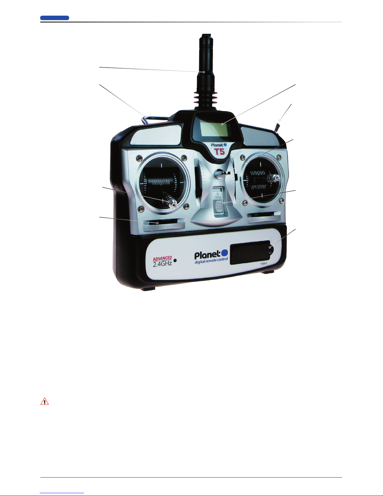
TRANSMITTER FEATURES
Aerial
Carry handle
Neck strap hang point
Battery status LCD
5th channel switch
Dual axis control
stick with adjustable
height/spring tension
Control trim
Reversing switches
ON/OFF switch
CONTROL TRIMS
These are used to fine trim the position of the servos.
CHANNEL 5 SWITCH
The 5th channel retract switch on the upper case operates a servo at a slow rate allowing for more realistic
deployment of spoilers, retractable undercarriage or flaps.
BATTERY STATUS LCD
This display provides a digital readout of Transmitter voltage. Stop flying and replace the batteries when voltage
display falls to 4.4V.
WARNING!
Failure to stop flying immediately when the display reads 4.4V or less may lead to loss of control!
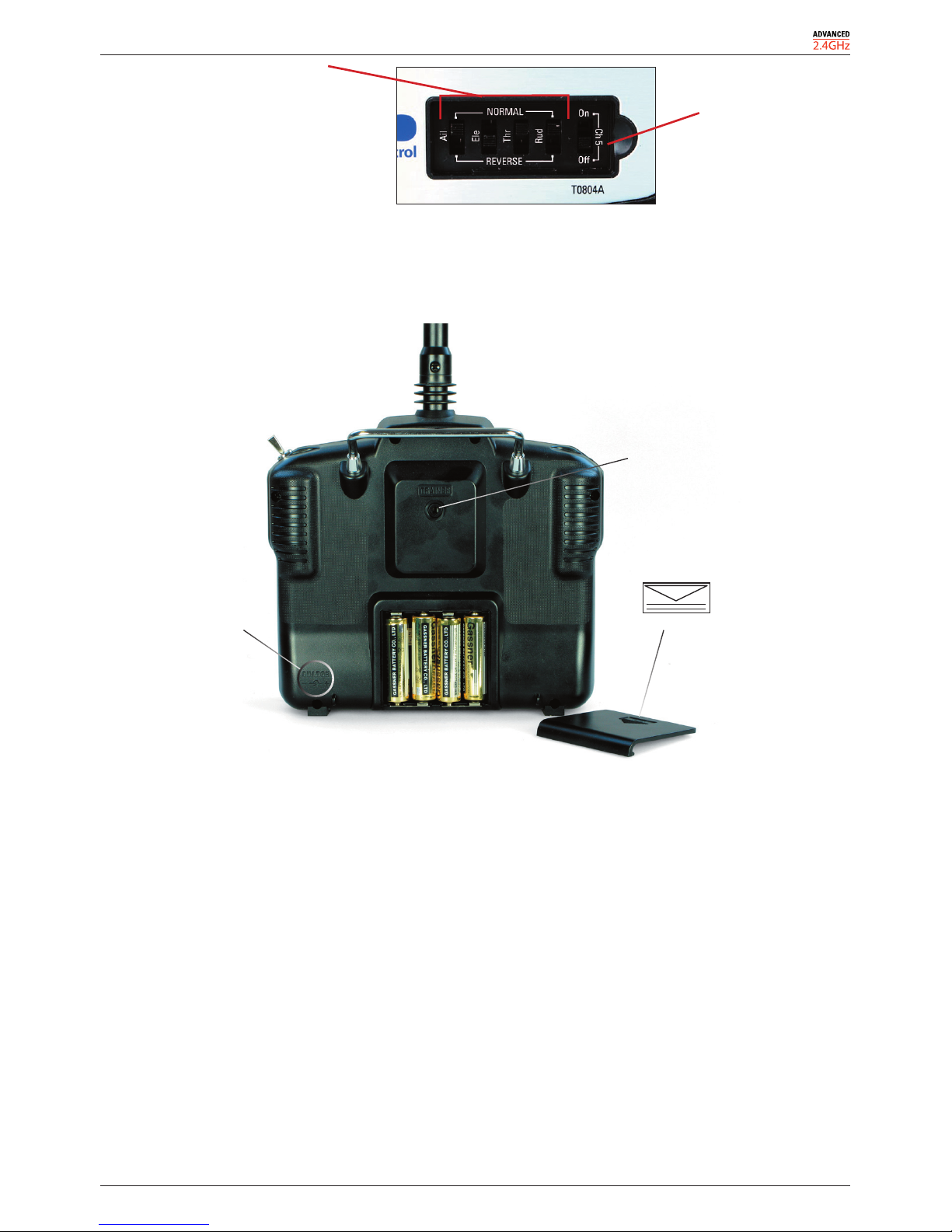
REVERSING SWITCHES
Reversing switches are used to reverse the direction of aileron, elevator, throttle and rudder functions.
The reversing switches are located beneath a removable cover on the front panel of the transmitter. See below:
Page 5
T5
Instruction Manual
3
Reversing switches
5th Channel
On/Off Switch
BATTERY FITTING
4 AA alkaline batteries are required. They are not supplied.
Install the 4 batteries into the battery compartment ensuring correct polarity is observed.
Simulator socket
Battery cover
Press and slide off cover
Charge socket
polarity
CHARGING SOCKET
Rechargeable AA batteries can be substituted for alkaline batteries.
N.B. Take note of the polarity diagram on the rear case when using a charger to charge rechargeable batteries.
SIMULATOR LEAD SOCKET
For optional Simulator lead connection.
Page 6

4
Planet•
rock-solid r/c
STICK TENSION ADJUSTMENT
Your T5 transmitter features adjustable spring tension on the 3 primary flying controls, aileron, elevator, rudder.
To adjust tension remove the 6 screws retaining the rear transmitter case as below:
Case screws
Case screws
Use a small cross head screwdriver to adjust spring tension:
Replace the case and screws carefully after adjustment.
N.B. This procedure exposes delicate electronics. You must not touch or allow anything to fall into the circuitry. If
you do not feel comfortable doing this, please ask your supplier for assistance.
STICK HEIGHT ADJUSTMENT
Use an allen key to slacken the stick end, adjust to desired height and retighten allen screw.
s
Page 7

T5
Instruction Manual
5
R6M RECEIVER
Binding microswitch
Binding LED
Receiver aerial
Upper pin-Signal
Lower pin-Negative
Centre pin-Positive
The R6M receiver is a precision electronic device forming the heart of your control system. It should be handled
carefully and protected from moisture, vibration and dust.
It has been designed to operate with small lightweight JP EnErG servos in a light duty environments, e.g. Park
Flyer aircraft, JP Twister co-axial helicopters. It should be noted that some model aircraft installations, for
example, those involving retractable undercarriage, flaps, etc, may impose high current loads/drain on receiver
and batteries. Therefore, always perform careful ground tests on your airborne equipment BEFORE flying and
always perform battery and circuit current checks after connecting servos to control surfaces or aircraft fixtures.
Note the observed current consumption under idle/running conditions and check that battery and circuit capacity
are sufficient for safe flight at all times under all conditions. If in doubt, run high current load servos from a
separate battery pack.
Take particular care of the gold-plated receiver pins when attaching or disconnecting connectors.
R6M DEPLOYMENT
The receiver should be secured and mounted in protective foam (JP No 5508000 not supplied) to protect and
cushion it in the event of impact or vibration: The electronics are sensitive to moisture or damp. Do not expose
the receiver to damp or wet conditions.
When installed in a model the aerial should be deployed perpendicular to the rear face of the receiver. The
receiver aerial is fragile. Do not expose it to vibration, stretching or contact with any object. Ensure that the
receiver aerial is arranged as in the picture below:
5508000 receiver/
battery packing
Aerial deployment
RECEIVER CONNECTIONS
The lower gold pin is negative, the centre pin is positive and the upper pin is signal.
No physical polarisation of connectors is provided therefore check carefully before making connections to the
receiver.
Servo connection to
channels 1:6 pins
Battery/switch connection
to battery ‘B’ pins
Negative lead
is lower
Page 8

6
Planet•
rock-solid r/c
R6M SPECIFICATIONS
Operation ........................................................................................ 4.8V to 6.0V
Idle current (transmitter and receiver on, no servos connected) ...40mA
WARNING!
Warning: The R6M Receiver must not be operated below 4.4V!
Warning: Incorrect connection may cause damage and/or receiver failure!
Warning: Exposure of the receiver to high vibration, damp or wet conditions may cause it to stop working!
SERVOS
Servos are not supplied.
The following JP EnErG servos have been extensively tested and flown with Planet 5 and should be used with this
system:
7712105 SUPER MICRO 6.0g SERVO (S6 EnErG)
7712110 SUPER MICRO 7.5g SERVO (S7.5 EnErG)
7712115 SUPER MICRO DIGITAL 7.5g SERVO (S7.5D EnErG)
BATTERY AND SWITCH
Batteries and switch are not supplied.
The folowing 4.8V battery and switch are recommended:
4405515 ENERG-PRO NiMH 4.8V AA-2100 FLAT
7721049 SWITCH & CHARGING HARNESS
BINDING TRANSMITTER TO RECEIVER
A working 2.4Ghz transmitter and receiver have a coded, 'bound' relationship with each other. The setting up of
this relationship is known as 'binding'.
In a 'bound' transmitter/receiver relationship the receiver is exclusively bound to your transmitter and can only
respond to signals received from that transmitter. It will not respond to any other device or transmitter.
Once a transmitter is bound to it's receiver, re-binding of transmitter and receiver is not normally required.
However, by binding your receiver, for example, to a friend's Planet 5 transmitter, the unique relationship between
your original transmitter and receiver will be broken. Should you wish to - or need to, re-establish or 'bind' your
transmitter with your receiver once more; proceed as follows:
HOW DO I RECOGNISE WHEN MY RECEIVER IS NOT BOUND?
Upon connecting the battery in the model the receiver status indicator LED will flash on and off slowly regardless
of whether the transmitter is switched on or not. Even when the transmitter is switched on; no control or change
in the slow flash of the LED will be seen.
HOW DO I BIND RECEIVER AND TRANSMITTER?
▼ 1. Switch off the transmitter.
▼ 2. Connect receiver battery. Press the binding microswitch on the receiver undersurface briefly once with
your fingernail or a small screwdriver.
Page 9

T5
Instruction Manual
7
Binding microswitch
Binding LED
▼ 3. The receiver status indicator will flash in groups of three.
Binding LED
flashing in threes
▼ 4. Switch on the transmitter.
As the signals are acquired, the Binding LED will flash briefly and then glow solidly a few seconds later
indicating a successful binding.
▼ 5. Operate your model as normal. The Binding LED glows solidly once bound with the transmitter.
TRANSMITTER USAGE
TRANSMITTER AERIAL POSITIONING
The transmitter aerial can be angled to optimise the transmitted signal. During operation keep the aerial pointing
upwards at all times. Do not fly with the aerial pointing downwards. Avoid pointing the aerial directly at your
model.
Keep the aerial pointing up–but not
directly at the model
RANGE AND POWER CHECK
▼ It is important to check the transmitter will operate the model satisfactorily at a safe range.
▼ In order to do this place your model on the ground and walk away from the model whilst operating the
swashplate/aileron controls. Have an assistant stand by the model and signal what the controls are doing
to confirm they operate correctly.
Check that the servos in the model operate without interference up to a distance of at least 100 metres.
▼ Ensure that fresh/charged batteries are being used for transmitter and receiver. Check that the transmitter
LED screen is displaying a voltage greater than 4.4V.
Page 10

8
Planet•
rock-solid r/c
WARNING!
Do not fly at 100 metres distance or greater. At distances of greater than 50 metres, it will become difficult to see
your model and at 100 metres it will be very difficult to see accurately and therefore to control safely.
We strongly recommend you fly no further away than 50 metres.
WARNING!
Planet 5 has been tested with many types of models and operated at ranges significantly greater than that
recommended. However, 2.4GHz equipemnt is affected by terrain, weather and obstacles to a significantly
greater degree than is conventional lower frequency R/C equipment. Therefore, do not be tempted to exceed
these specifications
Do not exceed the distances specified!
BATTERY STATUS LCD
This display provides a digital readout of Transmitter voltage. Stop flying and replace the batteries when voltage
display falls to 4.4V.
WARNING!
Failure to stop flying immediately when the display reads 4.4V or less may lead to loss of control!
MODE CHANGE SWITCH
Located at the bottom left of the main PCB is the mode change switch which facilitates conversion between
throttle left (Mode 1) layout and throttle right (Mode 2) layout.
Throttle right
Throttle left
FAILSAFE
If the transmitter signal is lost, the built-in failsafe operates and immediately drives the throttle to zero/no power
setting and the other controls are sent to their centre position.
WARNING!
This will result in your aircraft descending uncontrollably and immediately in whatever attitude is determined
by the dynamics and speed of your model at the time!
This failsafe setting is designed to prevent the model from flying away (and thereby posing a threat to the safety
of third parties).
Page 11

T5
Instruction Manual
9
THROTTLE LEFT (MODE 2) LAYOUT
Throttle trim Elevator trim
Rudder trim Aileron trim
Throttle/
Rudder
stick
Elevator/Aiileron
stick
Your Planet T5 can be flown in either throttle left or throttle right format.
he throttle stick is on the left side of the transmitter in the above arrangement.
The primary flying controls are shown here.
THROTTLE RIGHT (MODE 1)
Rudder trim Aileron trim
Elevator trim Throttle trim
Rudder/Elevator
stick
Throttle/Aileron
stick
The throttle stick is on the right side of the transmitter in the above arrangement.
The primary flying controls are shown here.
Page 12

10
Planet•
rock-solid r/c
FLIGHT CONTROLS - EXAMPLES
HELICOPTER MODE 2
▼ Each dual axis stick unit of your transmitter controls 2 helicopter functions (complete
with trimmers on each function) giving you control about all 4 axes of flight).
Rotate
nose right
Rotate
nose left
Climb
Descend
Crab
right
Crab
left
Forwards
Backwards
▼ The right stick operates the ‘cyclic’ steering controls and moves the helicopter forwards/backwards and
to the left/right in the horizontal plane.
Crab
right
Crab
left
Forwards
Backwards
▼ The left stick operates the throttle (main rotor speed) and yaw control.
Climb
Descend
Rotate
nose right
Rotate
nose left
Page 13

AIRCRAFT MODE 2
▼ Each dual axis stick unit of your transmitter controls 2 aircraft functions (complete with trimmers on each
function) giving you control about all 4 axes of flight). See above.
Rudder
Right
Rudder
Left
Throttle Up
Throttle Down
Aileron
Right
Aileron
Left
Elevator Down
Elevator Up
▼ The right stick operates the elevator which moves the model up/down and the aileron whcih rolls the
model left/right.
Down
Up
Left
Right
Aileron Controls:Elevator Controls:
▼ The left stick operates the throttle which increase and decreases speed and Rudder which turns the
model left/right.
Rudder Controls:
Left
Right
Page 14

12
Planet•
rock-solid r/c
HELICOPTER MODE 1
▼ Each dual axis stick unit of your transmitter controls 2 helicopter functions (complete with trimmers on
each function) giving you control about all 4 axes of flight).
Rotate
nose right
Rotate
nose left
Forwards
Backwards
Crab
right
Crab
left
Climb
Descend
▼ The right stick operates the throttle (main rotor speed) and the roll ‘cyclic’ steering controls which moves
the to the left/right in the horizontal plane.
Climb
Descend
Crab
right
Crab
left
▼ The left stick operates both yaw control and the forwards/backwards 'cyclic' steering controls.
Rotate
nose right
Rotate
nose left
Forwards
Backwards
Page 15

T5
Instruction Manual
13
AIRCRAFT MODE 1
▼ Each dual axis stick unit of your transmitter controls 2 aircraft functions (complete with trimmers on each
function) giving you control about all 4 axes of flight).
Rudder
Right
Rudder
Left
Elevator Down
Elevator Up
Aileron
Right
Aileron
Left
Throttle Up
Throttle Down
▼ The right stick operates the throttle which increase and decreases speed and the aileron whcih rolls the
model left/right.
Left
Right
Aileron Controls:
▼ The left stick operates the elevator which moves the model up/down and Rudder which turns the model
left/right.
Down
Up
Elevator Controls:
Rudder Controls:
Left
Right
Page 16

rock-solid r/c
Planet•
J Perkins Distribution, Lenham, UK
www.jperkinsdistribution.co.uk
 Loading...