

Page 1
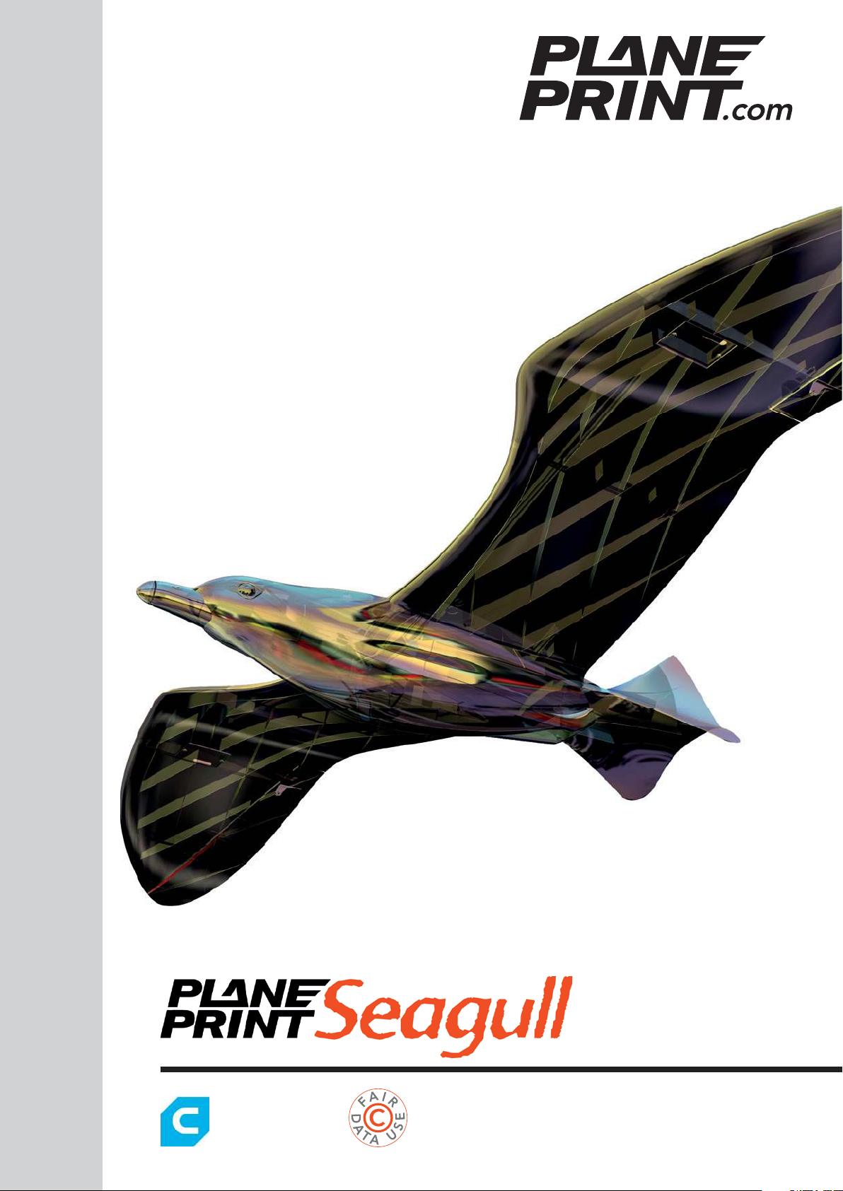
Glider version
NOTE: Slicing only
works with CURA!
You can fi nd the STL data
at www.planeprint.com
PRINTING & ASSEMBLING MANUAL
Page 2

PRINTING THE PARTS – PRINTING PROFILES
You may wonder why this 3D model is exclusive to CURA?
The most important thing with small RC model airplanes is always the size to weight ratio. The
lighter a model is, the better its flight characteristics and also the flight time is significantly increased.
With our unique design process, we manage to offer weight-relevant parts in a true 1-wall printing
process for both the outer skin and the filling. This allows us to save weight while maintaining the
necessary stability.
Here we show you how to make adjustments from a standard CURA profile.
For this model we need only 4, easy to create profiles.
It is important to follow the instructions from PLANEPRINT.com to slice the part correctly.
However, it can be useful to perfect your 3D printing by making some additional settings depending
on the printer and filament used.
For slicing all Planeprint
models, four profiles have
to be created in Cura:
PROFILE P1_fullbody
PROFILE P2_hollowbody
PROFILE P3_surface
PROFILE P4_flex
You can find the description at
www.planeprint.com/print
IMPORTANT FOR
THE 1-WALL-PRINT!
In order to print airfoils of the lowest possible weight with high stability, it is necessary to print with only one wall line (Nozzle 0.4
mm). Decisive here is the adhesion between
the layers! To achieve this, you must print at
a much higher temperature than normal. As
a guideline, 230 ° C is a good starting point.
The parts-cooling fan should be set to 0% or
a maximum of 20%. Since not every printer
works the same, it may be necessary to make
small adjustments to these settings.
The development of a complex, airworthy RC flight model to express on any standard 3D printer is
a very complex and extensive process. Therefore, we appeal to your fairness not to forward the STL
data you have acquired to third parties. Our STL files are provided with indelible copyright watermarks that can be verified at any time.
Thank you for your understanding and have fun with your PLANEPRINT MODEL!
SEAGULL GLIDER VERSION
PRINTING & ASSEMBLING MANUAL
© PLANEPRINT
2
Page 3
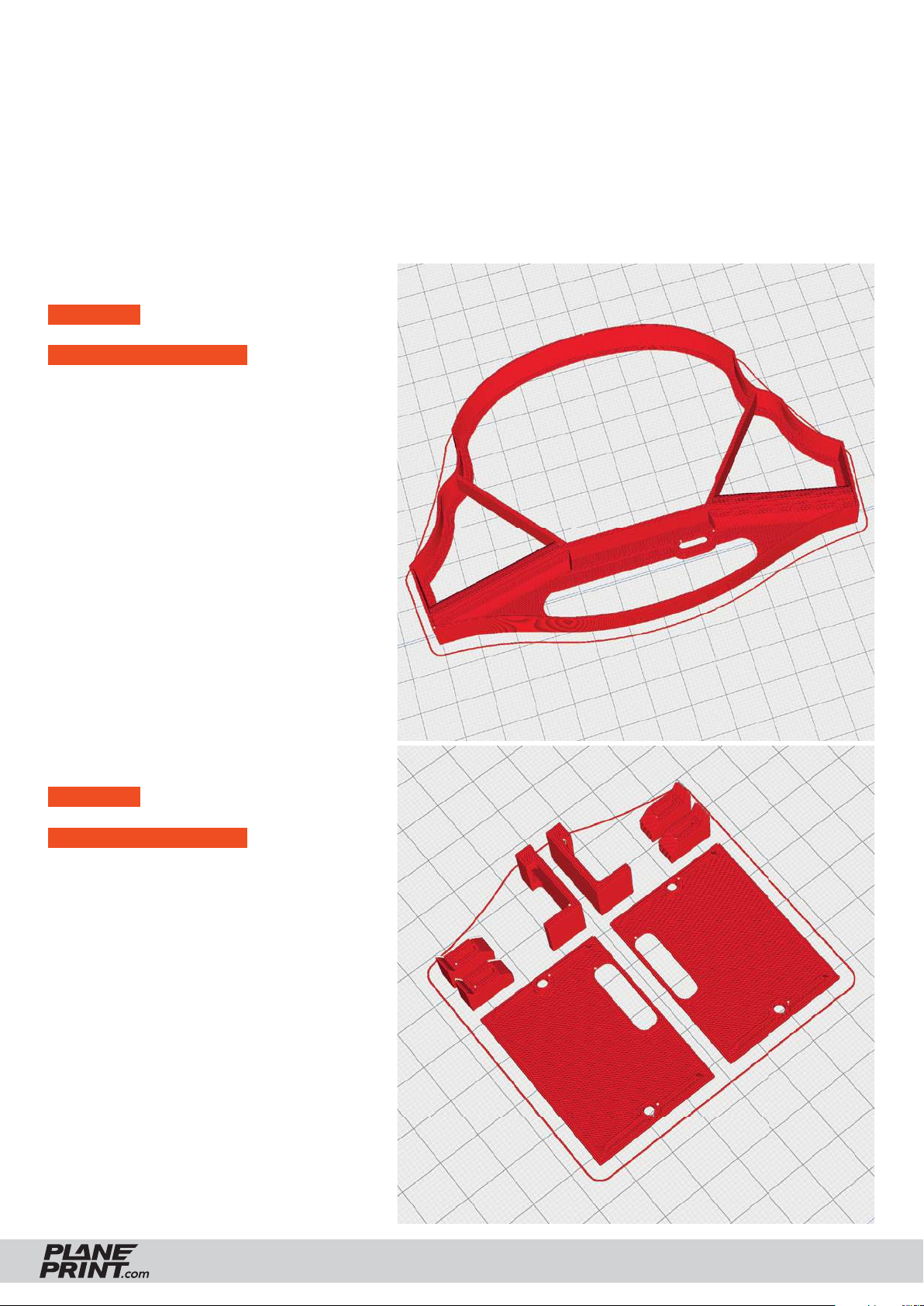
PROFILE P1_FULLBODY
The following parts must be sliced with the PROFILE P1_FULLBODY.
Please note the additional settings for the individual parts!
Central piece GLIDER_profi le1_sg.stl
MATERIAL PLA, Weight: ~ 11 g
ADDITIONAL SETTINGS
None required
Servo mount_profi le1_sg.stl
MATERIAL PLA, ~ 7 g
ADDITIONAL SETTINGS
None required
SEAGULL GLIDER VERSION
PRINTING & ASSEMBLING MANUAL
© PLANEPRINT
3
Page 4
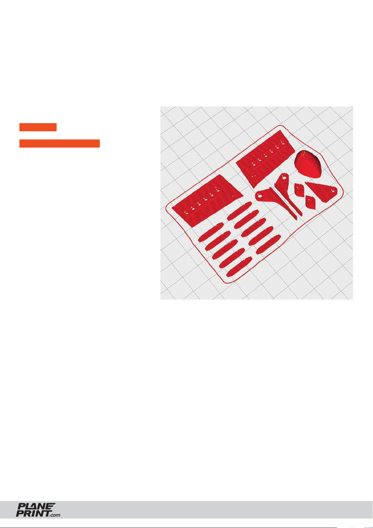
PROFILE P1_FULLBODY
The following parts must be sliced with the PROFILE P1_FULLBODY.
Please note the additional settings for the individual parts!
Small parts_profi le1_sg.stl
MATERIAL PLA, ~ 4 g
ADDITIONAL SETTINGS
None required
SEAGULL GLIDER VERSION
PRINTING & ASSEMBLING MANUAL
© PLANEPRINT
4
Page 5
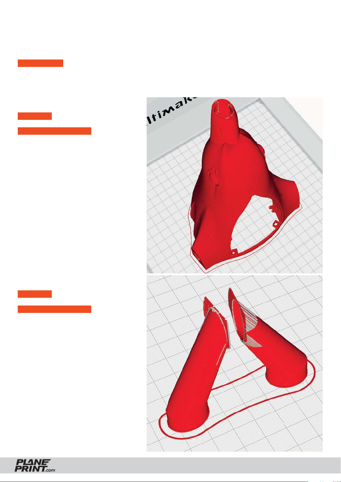
PROFILE P3_SURFACE PLA or Tough PLA
The following parts must be sliced with the PROFILE P3_SURFACE (1-wall-print).
Please note the additional settings for the individual parts!
PLEASE NOTE In profi le P3_SURFACE, there should not be more than one STL on the buildplate at the same
time, otherwise slicing errors can occur! Depending on your printer, a brim may not be required.
Fuselage 1-GLIDER_profi le3.stl
MATERIAL PLA, ~ 45 g
ADDITIONAL SETTINGS
None required
Wingmount-GLIDER_profi le3_sg.stl
MATERIAL PLA, ~ 2 g
ADDITIONAL SETTINGS
None required
SEAGULL GLIDER VERSION
PRINTING & ASSEMBLING MANUAL
© PLANEPRINT
5
Page 6
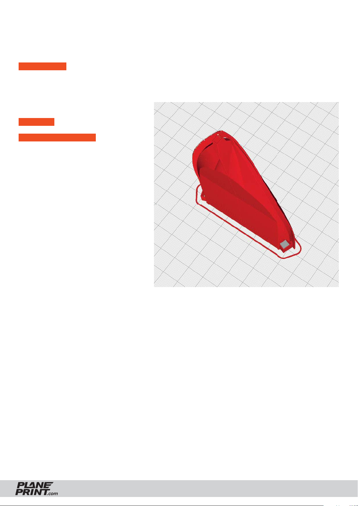
PROFILE P3_SURFACE PLA or Tough PLA
The following parts must be sliced with the PROFILE P3_SURFACE (1-wall-print).
Please note the additional settings for the individual parts!
PLEASE NOTE In profi le P3_SURFACE, there should not be more than one STL on the buildplate at the same
time, otherwise slicing errors can occur! Depending on your printer, a brim may not be required.
Cover-GLIDER_profi le3.stl
MATERIAL PLA, ~ 7 g
ADDITIONAL SETTINGS
None required
SEAGULL GLIDER VERSION
PRINTING & ASSEMBLING MANUAL
© PLANEPRINT
6
Page 7
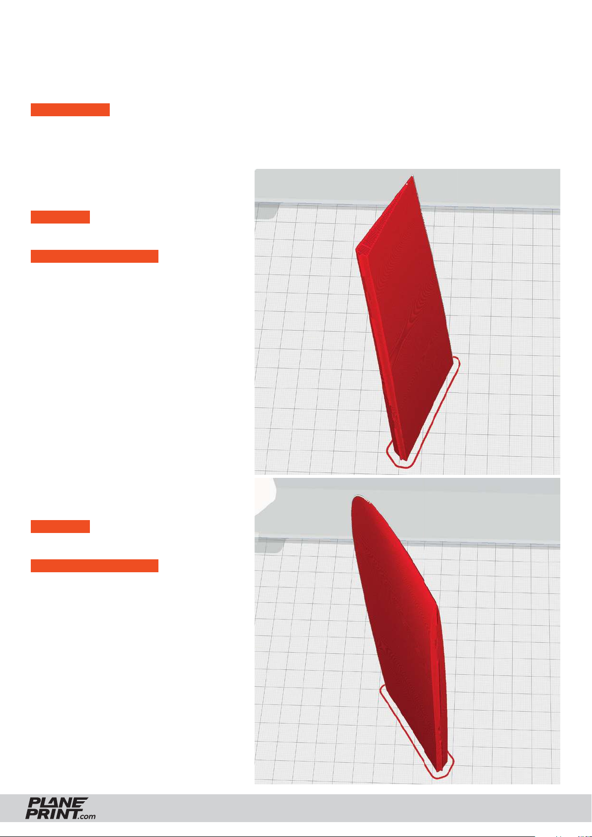
PROFILE P3_SURFACE Light-Weight LW-PLA
The following parts must be sliced with the PROFILE P3_SURFACE (1-wall-print).
Please note the additional settings for the individual parts!
PLEASE NOTE In profi le P3_SURFACE, there should not be more than one STL on the buildplate at
the same time, otherwise slicing errors can occur! Depending on your printer, a brim may not be required.
Aileron1-LW-left_profi le3_sg.stl
Aileron1-LW-right_profi le3_sg.stl
MATERIAL LW-PLA, ~ 10 g*
*Display in Cura. The actual weight is 6 grams
ADDITIONAL SETTINGS
- Setting Profi le3_Surface
- Flow 60 % or less
- Higher nozzle temperature
The optimal weight and suffi cient strength is achieved
with 60 % fl ow. Increase the temperature until the wall
thickness is 0.4 to 0.5 mm. (We print at 250° and 60% fl ow).
Aileron2-LW-left_profi le3_sg.stl
Aileron2-LW-right_profi le3_sg.stl
MATERIAL LW-PLA, ~ 12 g*
*Display in Cura. The actual weight is 8 grams
ADDITIONAL SETTINGS
- Setting Profi le3_Surface
- Flow 60 % or less
- Higher nozzle temperature
The optimal weight and suffi cient strength is achieved
with 60 % fl ow. Increase the temperature until the wall
thickness is 0.4 to 0.5 mm. (We print at 250° and 60% fl ow).
SEAGULL GLIDER VERSION
PRINTING & ASSEMBLING MANUAL
© PLANEPRINT
7
Page 8
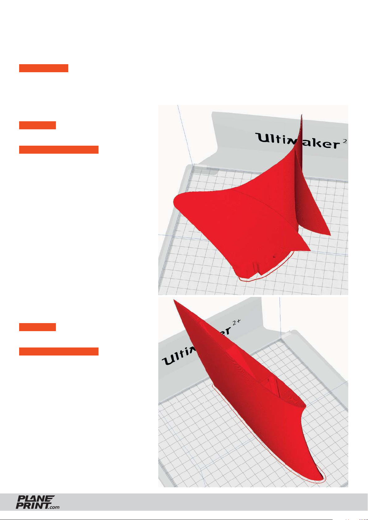
PROFILE P3_SURFACE Light-Weight LW-PLA
The following parts must be sliced with the PROFILE P3_SURFACE (1-wall-print).
Please note the additional settings for the individual parts!
PLEASE NOTE In profi le P3_SURFACE, there should not be more than one STL on the buildplate at
the same time, otherwise slicing errors can occur! Depending on your printer, a brim may not be required.
Tail-LW_profi le3_sg.stl
MATERIAL LW-PLA, ~ 35 g*
*Display in Cura. The actual weight is 19 grams
ADDITIONAL SETTINGS
- Setting Profi le3_Surface
- Flow 60 % or less
- Higher nozzle temperature
The optimal weight and suffi cient strength is achieved
with 60 % fl ow. Increase the temperature until the wall
thickness is 0.4 to 0.5 mm. (We print at 250° and 60% fl ow).
Wing 1-LW-left_profi le3_sg.stl
Wing 1-LW-right_profi le3_sg.stl
MATERIAL LW-PLA, ~ 56 g*
*Display in Cura. The actual weight is 29 grams
ADDITIONAL SETTINGS
- Setting Profi le3_Surface
- Flow 60 % or less
- Higher nozzle temperature
The optimal weight and suffi cient strength is achieved
with 60 % fl ow. Increase the temperature until the wall
thickness is 0.4 to 0.5 mm. (We print at 250° and 60% fl ow).
SEAGULL GLIDER VERSION
PRINTING & ASSEMBLING MANUAL
© PLANEPRINT
8
Page 9
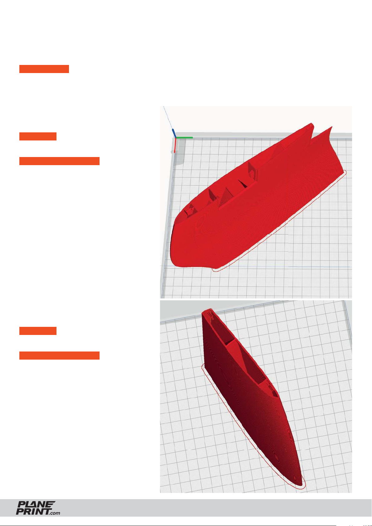
PROFILE P3_SURFACE Light-Weight LW-PLA
The following parts must be sliced with the PROFILE P3_SURFACE (1-wall-print).
Please note the additional settings for the individual parts!
PLEASE NOTE In profi le P3_SURFACE, there should not be more than one STL on the buildplate at the same
time, otherwise slicing errors can occur! Depending on your printer, a brim may not be required.
Wing 2-LW-left_profi le3_sg.stl
Wing 2-LW-right_profi le3_sg.stl
MATERIAL LW-PLA, ~ 55 g*
*Display in Cura. The actual weight is 28 grams
ADDITIONAL SETTINGS
• Z Seam Position: Wing left: Back Left
Wing right: Back Right
- Setting Profi le3_Surface
- Flow 60 % or less
- Higher nozzle temperature
The optimal weight and suffi cient strength is achieved
with 60 % fl ow. Increase the temperature until the wall
thickness is 0.4 to 0.5 mm. (We print at 250° and 60% fl ow).
Wing 3-LW-left_profi le3_sg.stl
Wing 3-LW-right_profi le3_sg.stl
MATERIAL LW-PLA, ~ 36 g*
*Display in Cura. The actual weight is 19 grams
ADDITIONAL SETTINGS
- Setting Profi le3_Surface
- Flow 60 % or less
- Higher nozzle temperature
The optimal weight and suffi cient strength is achieved
with 60 % fl ow. Increase the temperature until the wall
thickness is 0.4 to 0.5 mm. (We print at 250° and 60% fl ow).
SEAGULL GLIDER VERSION
PRINTING & ASSEMBLING MANUAL
© PLANEPRINT
9
Page 10
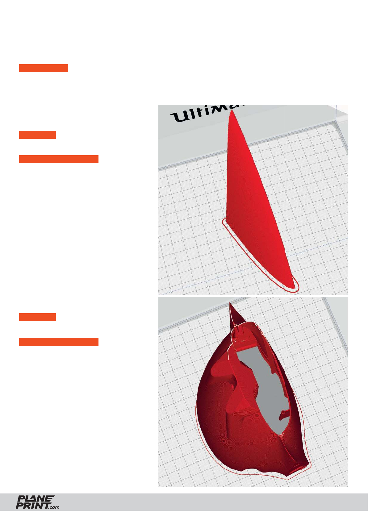
PROFILE P3_SURFACE Light-Weight LW-PLA
The following parts must be sliced with the PROFILE P3_SURFACE (1-wall-print).
Please note the additional settings for the individual parts!
PLEASE NOTE In profi le P3_SURFACE, there should not be more than one STL on the buildplate at the same
time, otherwise slicing errors can occur! Depending on your printer, a brim may not be required.
Wing 4-LW-left_profi le3_sg.stl
Wing 4-LW-right_profi le3_sg.stl
MATERIAL LW-PLA, ~ 12 g*
*Display in Cura. The actual weight is 8 grams
ADDITIONAL SETTINGS
- Setting Profi le3_Surface
- Flow 60 % or less
- Higher nozzle temperature
The optimal weight and suffi cient strength is achieved
with 60 % fl ow. Increase the temperature until the wall
thickness is 0.4 to 0.5 mm. (We print at 250° and 60% fl ow).
Fuselage 2-GLIDER-LW_profi le3_sg.stl
MATERIAL PLA, ~ 47 g*
*Display in Cura. The actual weight is 26 grams
ADDITIONAL SETTINGS
- Setting Profi le3_Surface
- Flow 60 % or less
- Higher nozzle temperature
The optimal weight and suffi cient strength is achieved
with 60 % fl ow. Increase the temperature until the wall
thickness is 0.4 to 0.5 mm. (We print at 250° and 60% fl ow).
SEAGULL GLIDER VERSION
PRINTING & ASSEMBLING MANUAL
© PLANEPRINT
10
Page 11
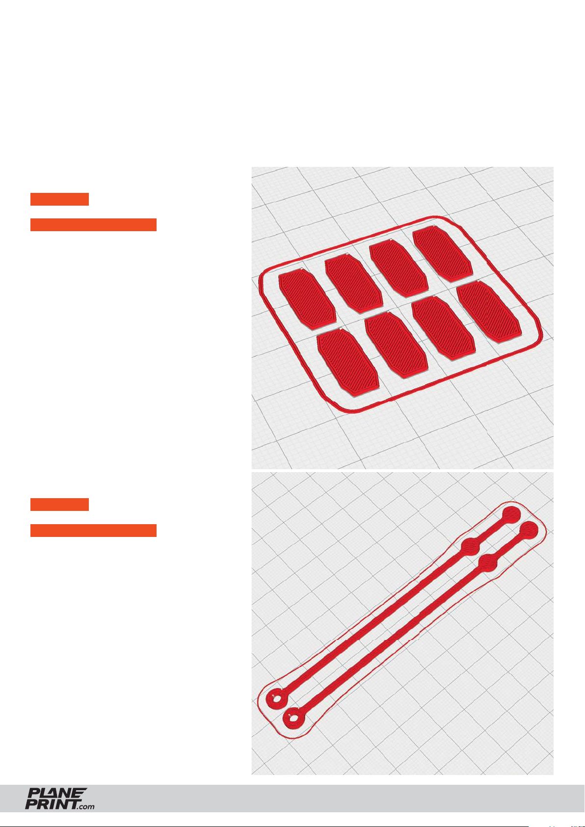
PROFILE P4_FLEX TPU A95
The following parts must be sliced with the PROFILE P4_FLEX.
Please note the additional settings for the individual parts!
Hinges_profi le4_sg.stl
MATERIAL TPU ~ A95, Weight: ~ 1 g
ADDITIONAL SETTINGS
None required
Tension belts_profi le4_sg.stl
MATERIAL TPU ~ A95, Weight: ~ 2 g
ADDITIONAL SETTINGS
• Infi ll Density: 100 %
SEAGULL GLIDER VERSION
PRINTING & ASSEMBLING MANUAL
© PLANEPRINT
11
Page 12
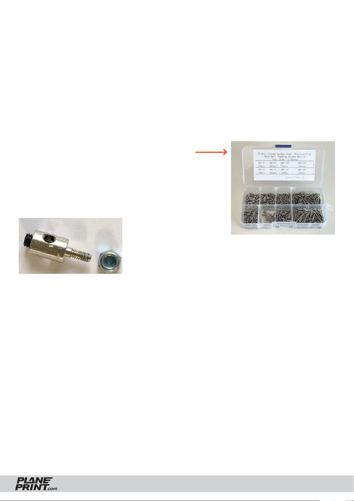
REQUIRED ACCESSOIRES
Filament
• normal PLA about 100 grams
• LW-PLA about 140 grams
We recommend using white (natural) LW-PLA, which heats up much less in direct sunlight.
• TPU (A95) about 5 grams
(ABSOLUTELY NECESSARY)
Materials
• some tapping screws Ø2*8mm
(simply search for: M2 flat head tapping screw assortment)
• CA super glue (liquid and liquid medium)
• CA activator
• Carbon tube Ø6mm*305mm (inside 4mm), 2 pieces
• Steel wire Ø0.8mm*400mm (or Ø1mm for the servo linkages)
• small Rod connection, 3 pieces
• Neodym Super Magnets 5x5x5mm, 4 pieces
• Self adhesive velcro tape
Rod connection
Tools
• Cutter knife
• small Philips screwdriver
• Drill Ø1.5mm
• needle-nose pliers
SEAGULL GLIDER VERSION
PRINTING & ASSEMBLING MANUAL
© PLANEPRINT
12
Page 13
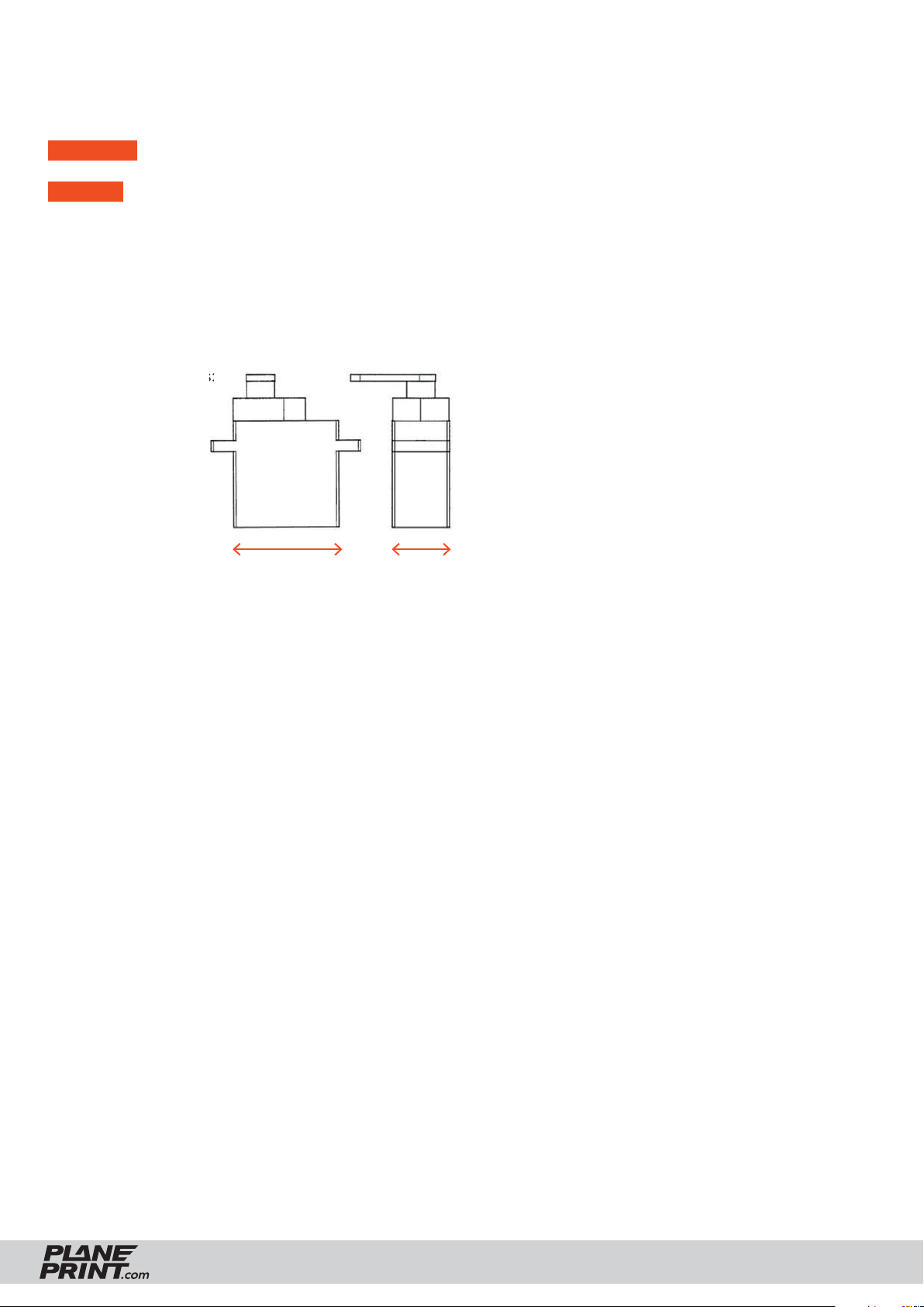
RC COMPONENTS
RECEIVER 3 Channel
SERVOS 3 pieces
• PLANET-HOBBY ECO PLUS
• PICCO 8 DIGITAL SERVO
• Diamond D47
• Hitec HS 40 Eco Servo 4,8g
• Hitec HS-5055MG
Maximum dimensions:Maximum dimensions:
max. 23 mm max. 13 mm
SEAGULL GLIDER VERSION
PRINTING & ASSEMBLING MANUAL
© PLANEPRINT
13
Page 14
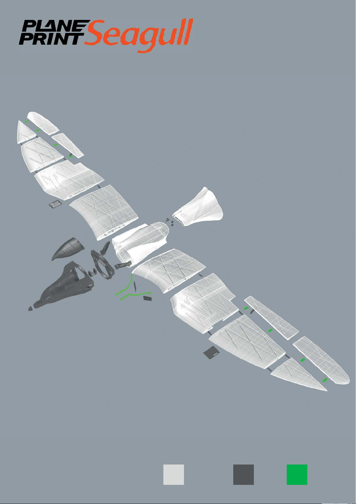
GLIDER version
PLALW-PLA TPU
Page 15
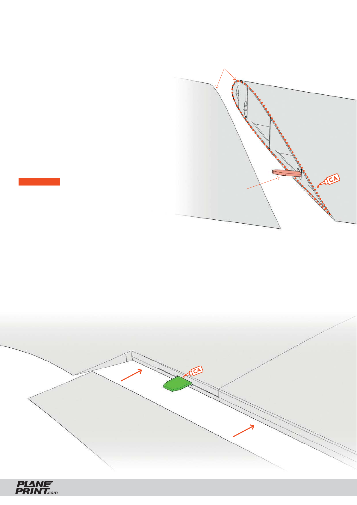
ASSEMBLING MANUAL – Basic information
This surfaces should be sanded
Gluing the parts
To glue the fuselage and wing parts well,
use medium-liquid CA adhesive.
First check whether the parts go well together.
Then apply a lot of CA glue to the part with the
connections and all surfaces that will touch later
(except the bowden tubes!). Put the parts together and align the parts perfectly. If glue comes
out, wipe with a cloth. Then spray activator spray
on the glue points.
IMPORTANT For a strong connection, the
adhesive surfaces should be sanded. Please only
use fresh CA glue and activator spray for curing!
The adhesive connections must hold perfectly!
Interconnect
Installation of the TPU hinges
First insert the hinge into the wing and add a drop of liquid CA adhesive into
the gap. Wait for the glue to drain completely, then spray the activator on it.
Then put the flap in the wing and put a drop of CA glue on the hinge.
Wait again for the glue to run in, and then spray the activator on it.
Do not use too much glue, the flap must move easily!
medium l.
thin
SEAGULL GLIDER VERSION
PRINTING & ASSEMBLING MANUAL
© PLANEPRINT
15
Page 16
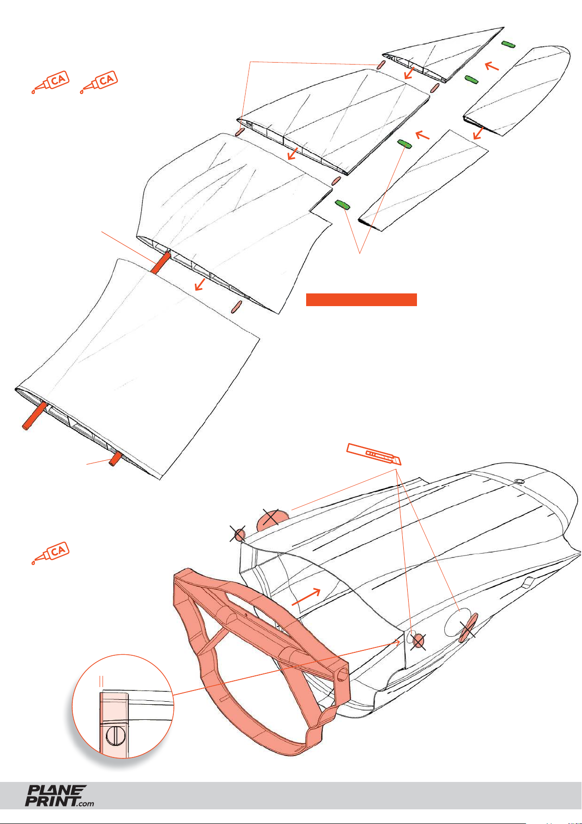
Wings assembly
medium l. thin
Use the carbon tube for
exact positioning of the
wing parts. The tube
should not be glued!
Small parts_profi le1_sg.stl
Wing 3-LW-right_profi le3_sg.stl
Wing 4-LW-right_profi le3_sg.stl
Aileron 2-LW-right_profi le3_sg.stl
Aileron 1-LW-right_profi le3_sg.stl
Carbon tube
Ø6mm*305mm
Carbon tube
Ø6mm*38mm
Wing 2-LW-right_profi le3_sg.stl
Wing 1-LW-right_profi le3_sg.stl
Hinges_profi le4_sg.stl
CARBON TUBE INFO
Wing: if the carbon tube is too loose, just put
some tape on it.
Fuselage (Central piece): Here the fi t is somewhat
tighter because the carbon tube must fi t well. If it is
too stiff, you can open it up a bit with a 6mm drill.
You can also use a piece of carbon tube as a drill.
Due to the frictional heat, the PLA adapts.
Remove Support
Fuselage assembly
thin
Pin the parts together
and then let thin CA
glue run into the gap.
Seen from
the side:
2 mm
SEAGULL GLIDER VERSION
Fuselage 2-GLIDER-LW_profi le3_sg.stl
Central piece GLIDER_profi le1_sg.stl
PRINTING & ASSEMBLING MANUAL
© PLANEPRINT
16
Page 17
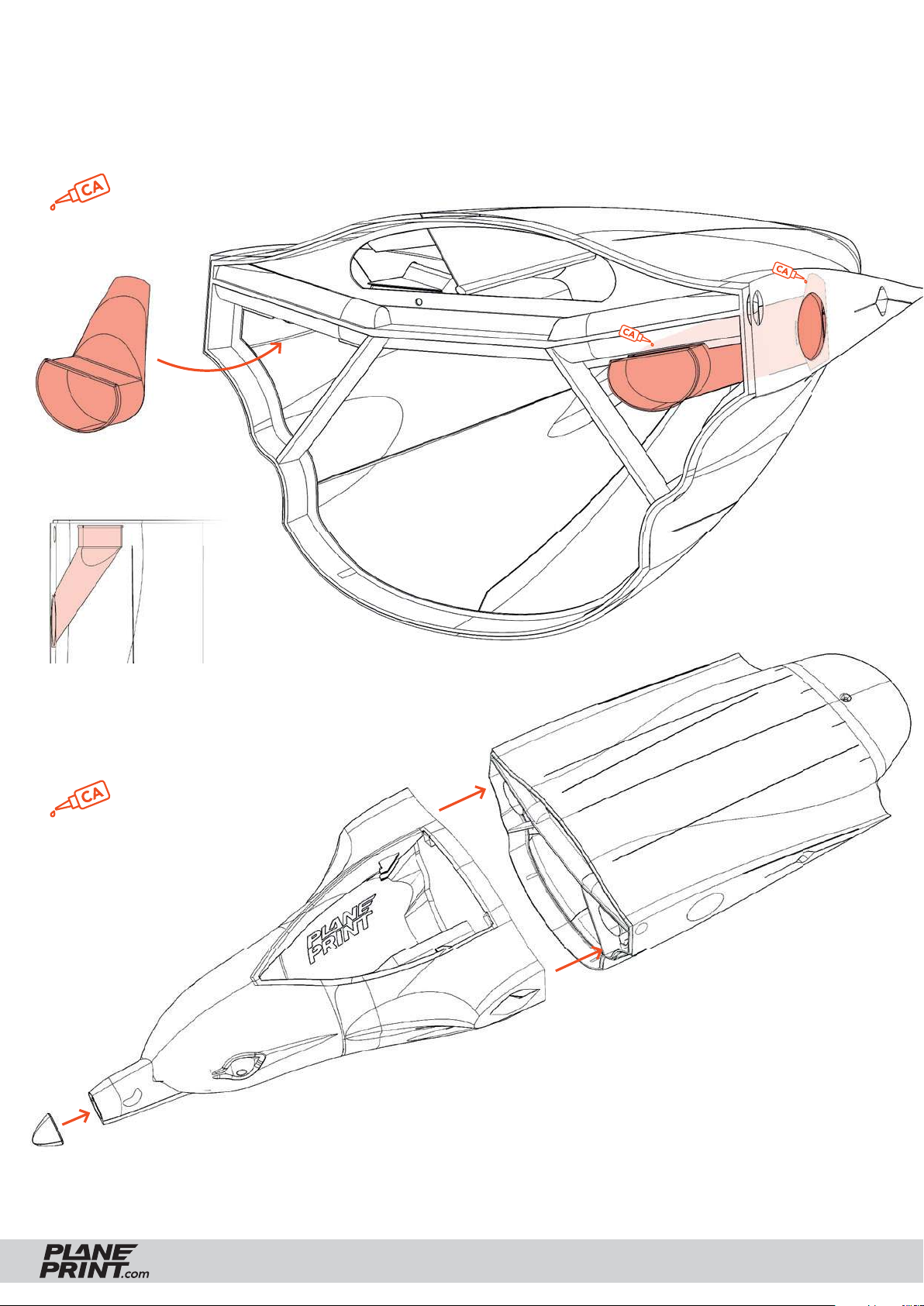
Fuselage assembly
Assemble the parts as shown in the picture.
medium l.
Wingmount-GLIDER_profi le3_sg.stl
from above
medium l.
Small parts_profi le1_sg.stl
Fuselage 1-GLIDER-LW_profi le3_sg.stl
SEAGULL GLIDER VERSION
Fuselage 2-GLIDER-LW_profi le3_sg.stl
PRINTING & ASSEMBLING MANUAL
© PLANEPRINT
17
Page 18
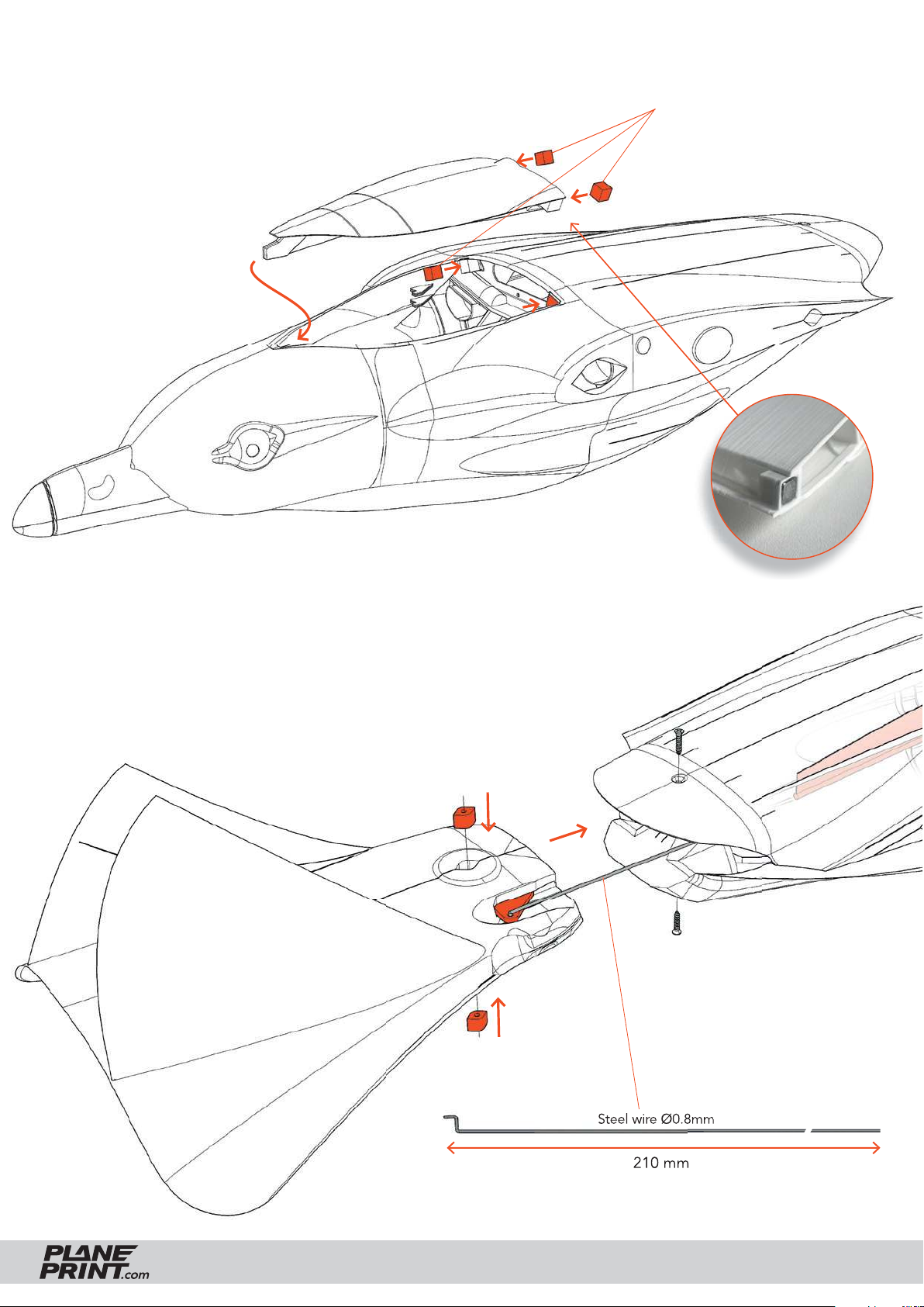
Cover mount
Put the four magnets into
the gaps, usually no glue is
needed.
Pay attention to the
alignment of the magnets
to each other!
Neodym Super
Magnets 5x5x5 mm
Tailplane assembly
Tape the three parts (
picture, insert the steel wire into the rudder horn and insert it into
the bowden in the fuselage. Then insert the tail into the fuselage
and screw it into the joint from above and below.
Make sure that the tail moves easily!
Small parts_profi le1.stl) as shown in the
Small parts_profi le1_sg.stl
Tail-LW_profi le3_sg.stl
Bowden
Tapping screws
Ø2*10mm
SEAGULL GLIDER VERSION
PRINTING & ASSEMBLING MANUAL
© PLANEPRINT
18
Page 19
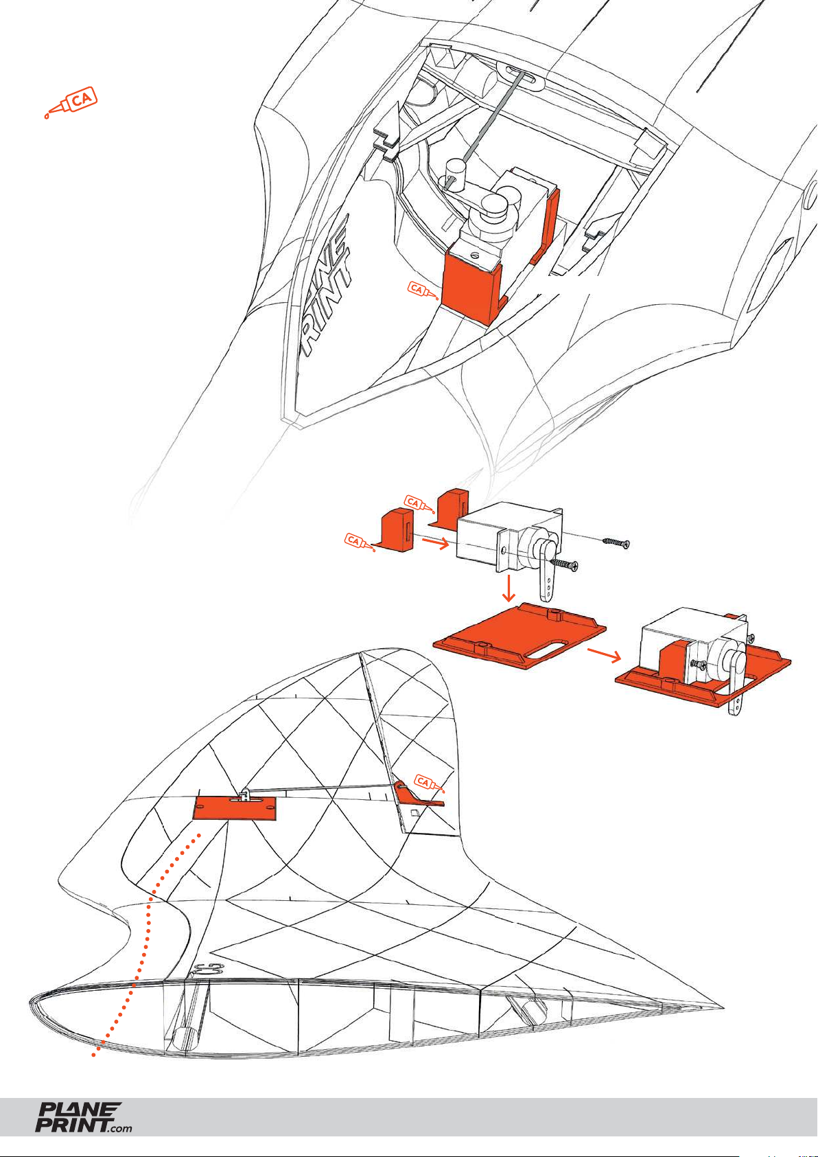
Rudder Servo
medium l.
Servo mount-GLIDER_profi le1_sg.stl
Aileron Servo
Assemble the parts as shown here.
Tighten the servo cover with tapping
screws. The holes in the wing must
be drilled beforehand. The easiest
way to do this is to heat a piece of
steel wire with a fl ame to melt the
hole for the screw.
Servo mount-GLIDER_profi le1_sg.stl
Cable duct
SEAGULL GLIDER VERSION
PRINTING & ASSEMBLING MANUAL
© PLANEPRINT
19
Page 20
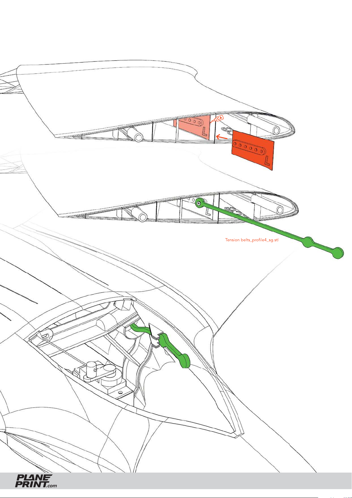
Wing mounting system
Glue the retaining plate to this rib of
the wing and then tighten the tension
belt to the outermost screw.
Small parts_profi le1_sg.stl
Tension belts_profi le4_sg.stl
Attach the wing to the fuselage and
tighten the tension belt between the
bracket at the front. If the tension
belt is too loose, tighten it a little
further inside the wing.
SEAGULL GLIDER VERSION
PRINTING & ASSEMBLING MANUAL
© PLANEPRINT
20
Page 21
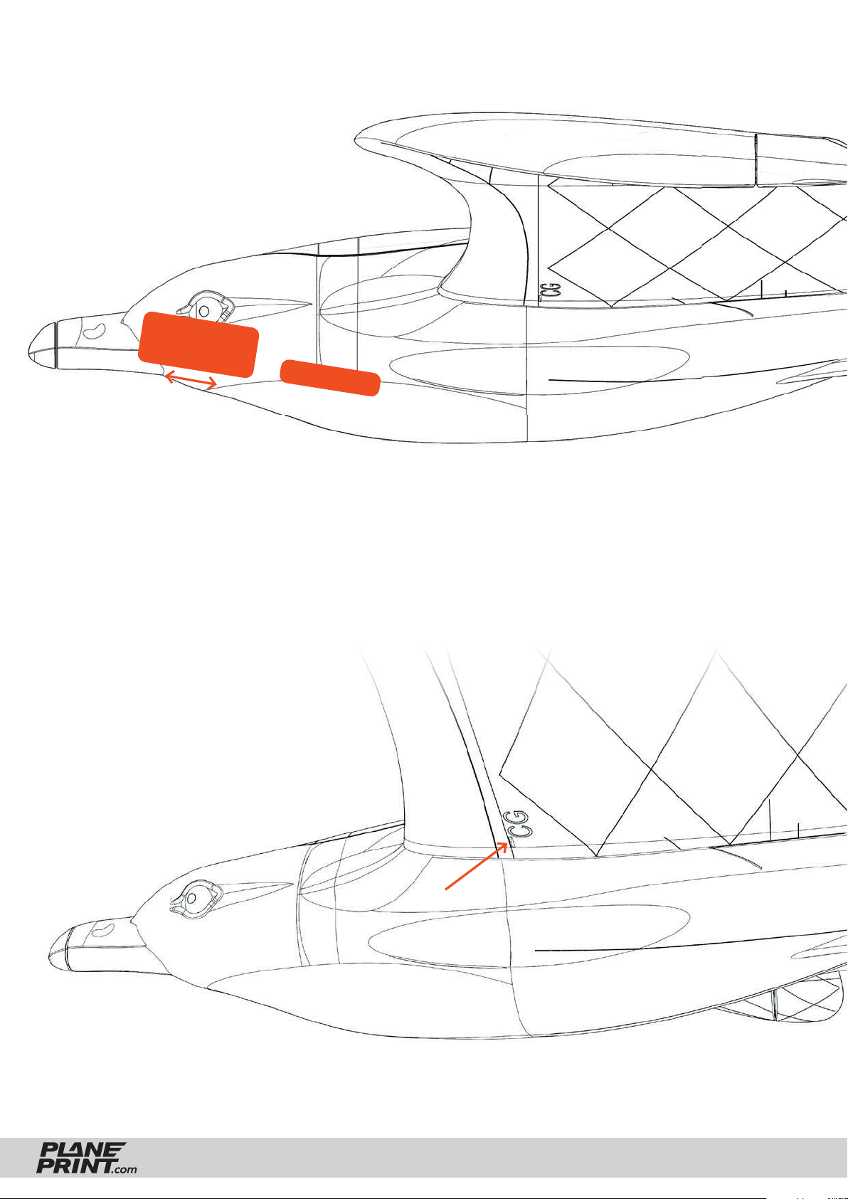
RC components
Use self-adhesive Velcro tape
to attach the RC components.
Battery
Set the exact CG by
positioning the battery.
Receiver
Center of Gravity (CG)
The aircraft must balance these points.
SEAGULL GLIDER VERSION
PRINTING & ASSEMBLING MANUAL
© PLANEPRINT
21
Page 22
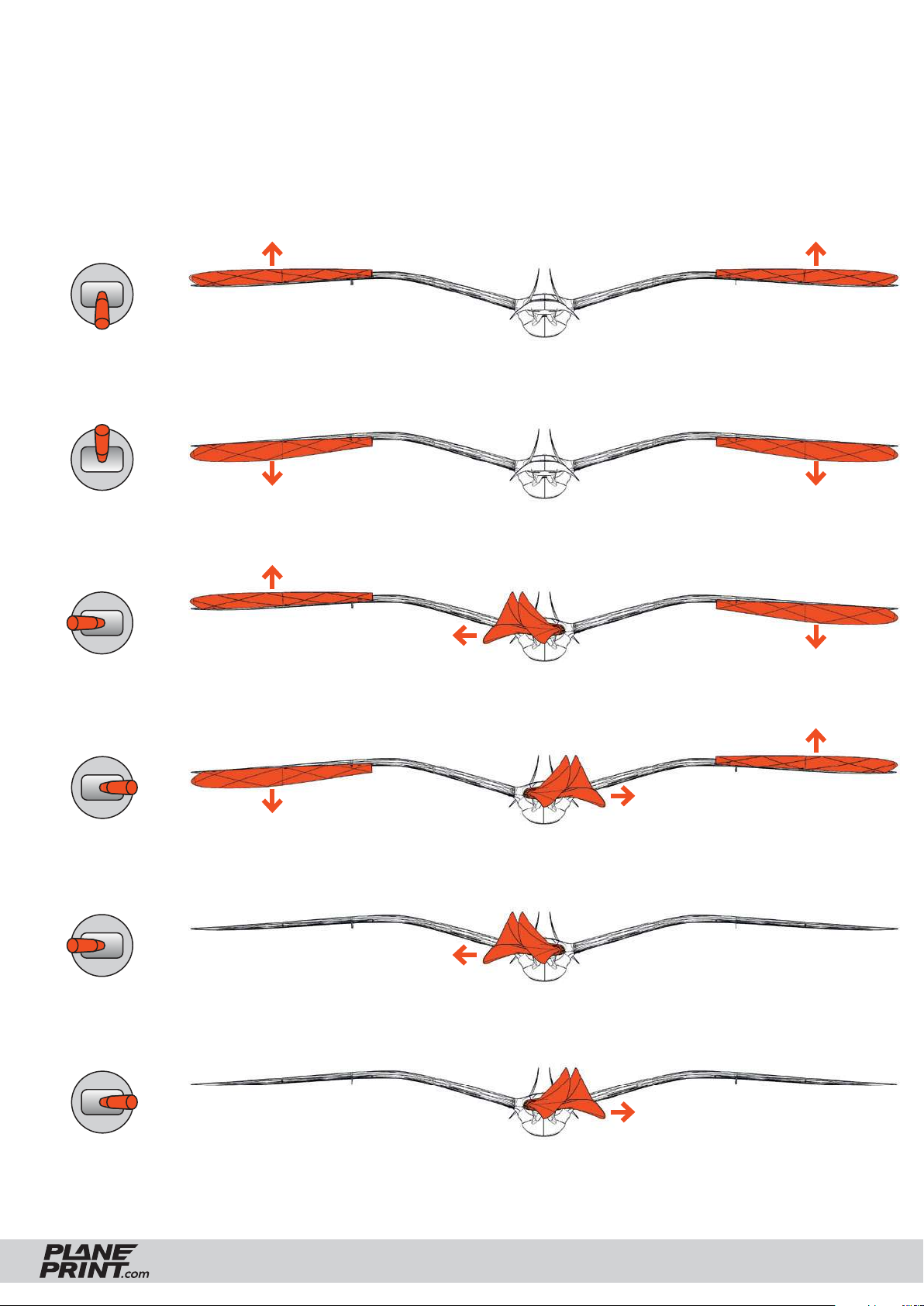
Control Direction Test
Turn on the transmitter and connect the battery.
When checking the control directions, look at the aircraft from behind.
Elevator up
Elevator down
Aileron left
Aileron right
Rudder left
Rudder right
SEAGULL GLIDER VERSION
PRINTING & ASSEMBLING MANUAL
© PLANEPRINT
22
Page 23
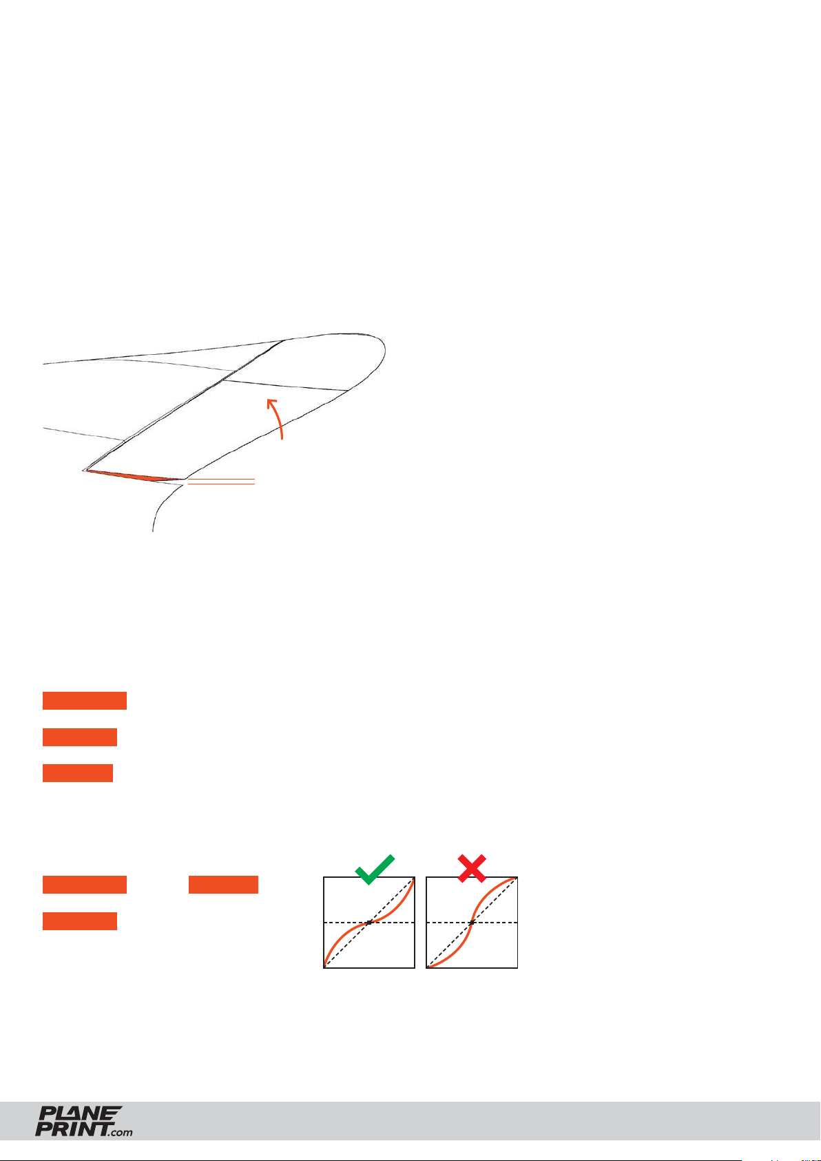
SETTINGS FOR FLYING
Since the Seagull requires the simultaneous use of aileron and rudder to initiate the turn for optimum
flight characteristics, we recommend mixing these functions electronically. This means that with the
aileron, the rudder also moves a little. We recommend about 50 %. When the rudder is actuated,
only the rudder should be moved.
Setting the servo travel
With the recommended CG, the basic setting of the ailerons/elevators should be as shown here:
Aileron/Elevator default setting:
2 mm
The Seagull has the maximum flight performance in gliding flight when the CG is a little further back.
After a few flights you can carefully move the CG a bit backwards until the ailerons/elevators can be
adjusted neutrally (no longer 2 mm upwards).
Deviating from this setting, this maximum travel must be set:
ELEVATOR up: 11 mm, down: 11 mm
AILERON up: 11 mm, down: 11 mm
RUDDER left/right: 30 mm
Expo setting
ELEVATOR 20 % RUDDER 0 %
AILERON 20 %
SEAGULL GLIDER VERSION
(for some remote
controls a minus
has to be in front
of the number)
PRINTING & ASSEMBLING MANUAL
© PLANEPRINT
23
Page 24
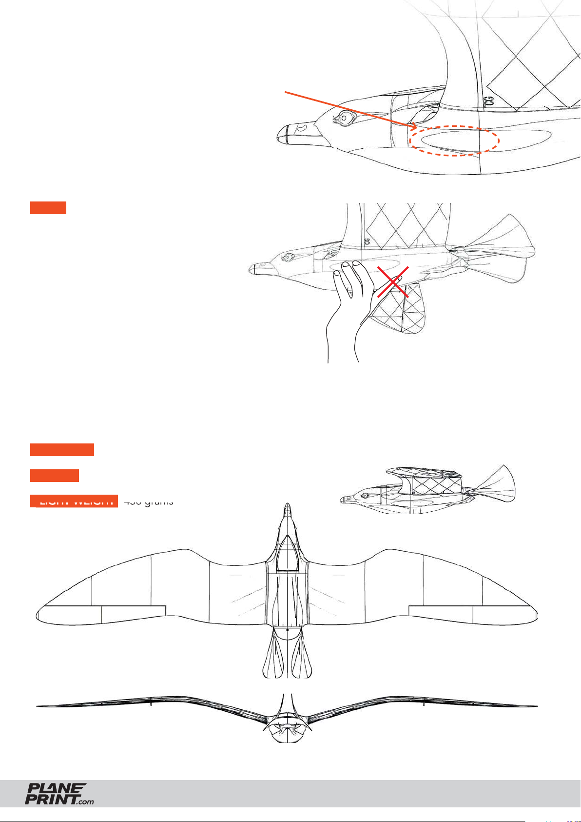
Takeoff from the hand
For safe launching, you should hold the Seagull
at the marked spot in the forward fuselage area.
For better grip, this area should be roughened
slightly with sandpaper.
NOTE When throwing, it is important
that the bird is pulled forward, not pushed.
Therefore you should not support it behind
with your index fi nger (see picture)!
TECHNICAL SPECIFICATIONS
WINGSPAN 1500 mm/59 inches
LENGHT 530 mm/20.8 inches
FLIGHT WEIGHT 436 grams
SEAGULL GLIDER VERSION
PRINTING & ASSEMBLING MANUAL
© PLANEPRINT
24
Page 25

AGE RECOMMENDATION 14+
NOT FOR CHILDREN UNDER 14 YEARS.
THIS IS NOT A TOY!
By using the download data, an RC model airplane, called
„model“ for short, can be manufactured using a 3D printer.
As a user of this model, only you are responsible for safe
operation that does not endanger you or others, or that
does not damage the model or property of others.
PLANEPRINT.com assumes no responsibility for damage to
persons and property caused by pressure, transport or use
of the product. Filaments, printing supplies, hardware or
consumables that can not be used after faulty 3D printing
will not be replaced by PLANEPRINT.com in any way.
When operating, always keep a safe distance from your
model in all directions to avoid collisions and injuries.
This model is controlled by a radio signal. Radio signals can
be disturbed from outside without being able to influence
it. Interference can lead to a temporary loss of control.
Always operate your model on open terrains, far from cars,
traffic and people.
Always follow the instructions and warnings for this product
and any optional accessories (servos, receivers, motors,
propellers, chargers, rechargeable batteries, etc.) carefully.
Avoid water contact with all components that are not specially designed and protected. Moisture damages the electronics.
Never take an item of the model or accessory in your mouth
as this can lead to severe injuries or even death.
Never operate your model with low batteries in the transmitter or model.
Always keep the model in view and under control.
Use only fully charged batteries.
Always keep the transmitter switched on when the model
is switched on.
Always remove the battery before disassembling the model.
Keep moving parts clean and dry at all times.
Always allow the parts to cool before touching them.
Always remove the battery after use.
Make sure that the Failsafe is properly set before the flight.
Keep all chemicals, small parts and electrical components
out of the reach of children.
We develop our models to the best of our knowledge and belief.
We accept no liability for consequential damage and injuries
caused by improper use. Please be careful when handling
motors, batteries and propellers and only move your model with
insurance and in approved places!
Never operate the model with damaged wiring.
Never touch moving parts.
© PLANEPRINT.com, A-6021 Innsbruck, Conradstraße 6, [email protected]
© Design STL files by René Marschall • Layout: marschall designlab, marschall.cc
 Loading...