

Page 1
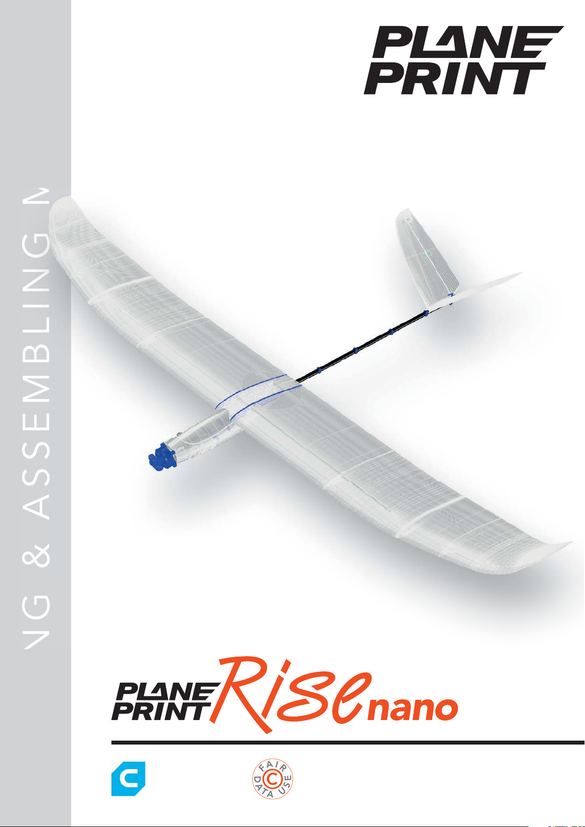
PRINTING & ASSEMBLING MANUALP R I N T I N G & A S S E M B L I N G M A N U A LP R I N T I N G & A S S E M B L I N G M A N U A LP R I N T I N G & A S S E M B L I N G M A N U A L
NOTE: Slicing only
works with CURA!
You can fi nd the STL data
at www.planeprint.com
Page 2
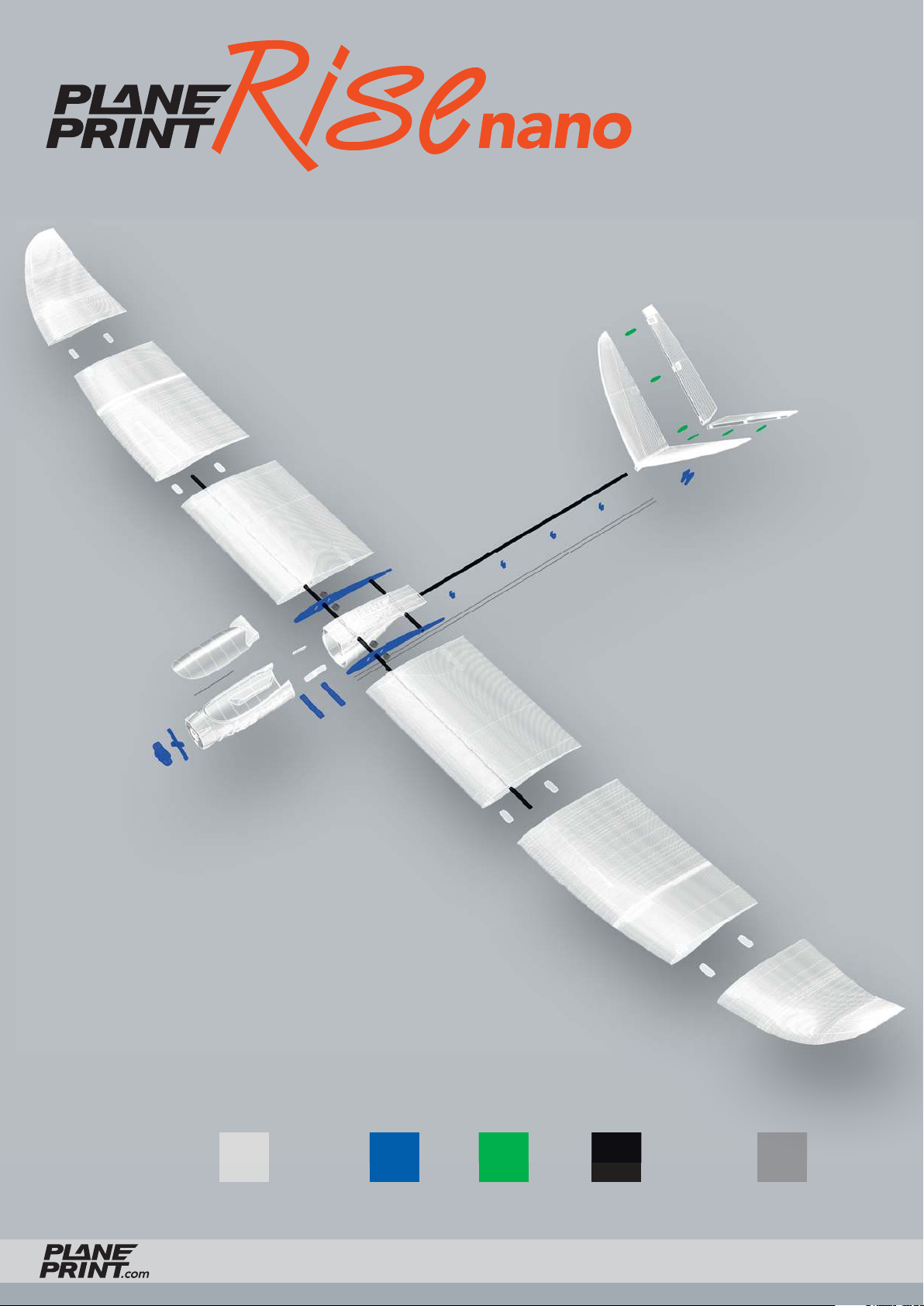
PLALW-PLA TPU CARBON STEEL
RISE NANO
PRINTING & ASSEMBLING MANUAL
© PLANEPRINT
2
Page 3
RC Components
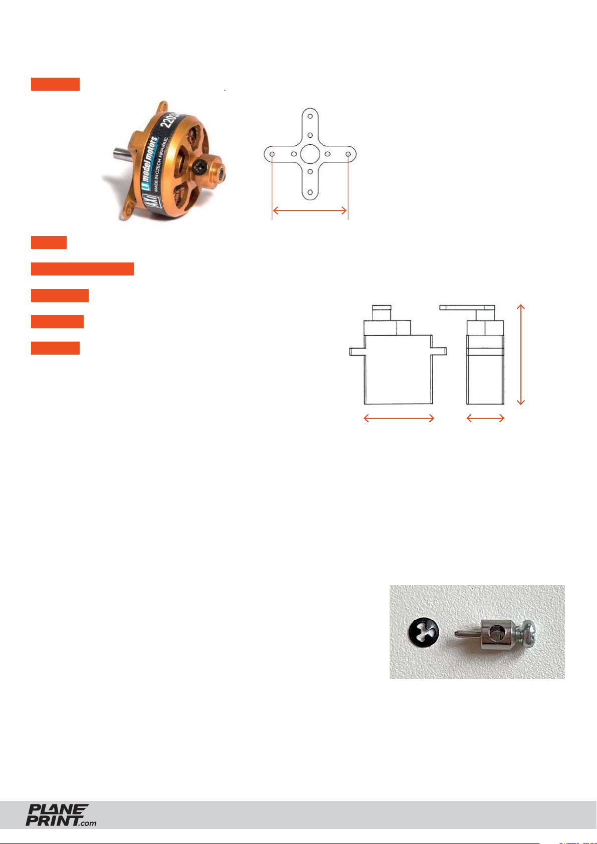
ENGINE AXI 2203/40 VPP or comparable indoor-20 grams-motors.
PROP Aeronaut folding prop 6x3 or comparable, also possible 6x4, 7x3, 7x4
BEC-CONTROLLER 15 A (one matching the motor)
RECEIVER 3 Channel
BATTERY 2S Lipo, 350 MaH (ideal weight 24 to 27 grams)
SERVOS • Stemedu Micro 3.7g Servo GH-S37D
• PLANET-HOBBY ECO PLUS
• PICCO 8 DIGITAL SERVO
• Diamond D47
• Hitec HS 40 Eco Servo 4,8g
or similar in the same size, 2 pieces
There are also ready-made indoor drive sets with motor, servos and battery available from many dealers.
31 mm
max. 22 mm
max. 27 mm
max. 8.5 mm
Required accessoires – basic equipment
• LW-PLA (cannot be replaced by PLA!), ~100 grams
• PLA or Tough PLA, ~20 grams
• TPU A95, ~10 grams
Rod connection hole 1 mm
• CA super glue (liquid and liquid medium)
• CA activator
• Steel wire Ø0.8*1000mm, 1 piece
• Carbon rod Ø4*1000mm, 1 piece
• Rod connection small, 2 pieces
• Neodym-Super-Magnet 5x5x5mm, 4 pieces
Tools
Cutter knife, Drill, small Philips screwdriver, Sandpaper,
Metal saw, Needle nose pliers
RISE NANO
PRINTING & ASSEMBLING MANUAL
© PLANEPRINT
3
Page 4
Printing the parts – Printing profiles
This manual is constantly being improved and supplemented, we recommend downloading
the latest version from our website before building.
For slicing all Planeprint
Important for the
models, these profiles have
1-wall-print (P3, P5)!
to be created in Cura:
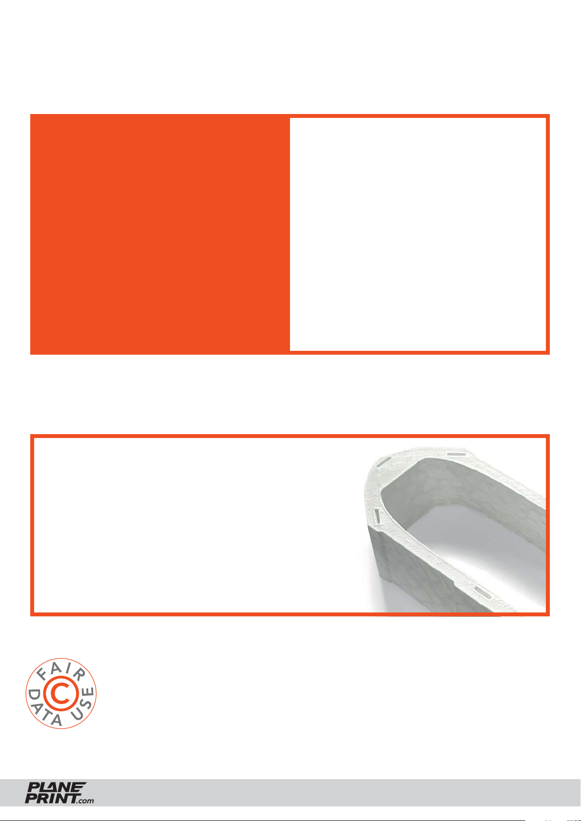
In order to print airfoils of the lowest possi-
PROFILE P1_Fullbody
PROFILE P2_Hollowbody
PROFILE P3_Surface
PROFILE P4_Flex
PROFILE P5_Gyroid
You can find the description at
www.planeprint.com/print
For the new PROFILE P5_Gyroid it is essential to use Cura Version 5 or later, It will work with
older versions, but the weight of the parts will be higher and the printing time longer.
ble weight with high stability, it is necessary to print with only one wall line (Nozzle 0.4
mm). Decisive here is the adhesion between
the layers! To achieve this, you must print at
a much higher temperature than normal. As
a guideline, 230° C is a good starting point.
The parts-cooling fan should be set to 0% or
a maximum of 20%. Since not every printer
works the same, it may be necessary to make
small adjustments to these settings.
PROFILE P5_Gyroid
It is essential for the necessary stability of the LW parts
printed with PROFILE_5 are as stable as possible. Please
use a test part to check the strength by fracture tests. It must
not break along the layer lines under any circumstances! Also
note that the printing temperature for LW-PLA is as low as
possible to obtain a wall thickness of 0.4 to 0.6 mm at a flow
of 60 to 70 % (depending on brand).
Caution: at too high temperatures, LW-PLA becomes brittle
and breaks more easily.
The development of a complex, airworthy RC flight model to express on any standard 3D printer is a very complex and extensive process. Therefore, we appeal to
your fairness not to forward the STL data you have acquired to third parties.
Thank you for your understanding and have fun with your PLANEPRINT MODEL!
RISE NANO
PRINTING & ASSEMBLING MANUAL
© PLANEPRINT
4
Page 5
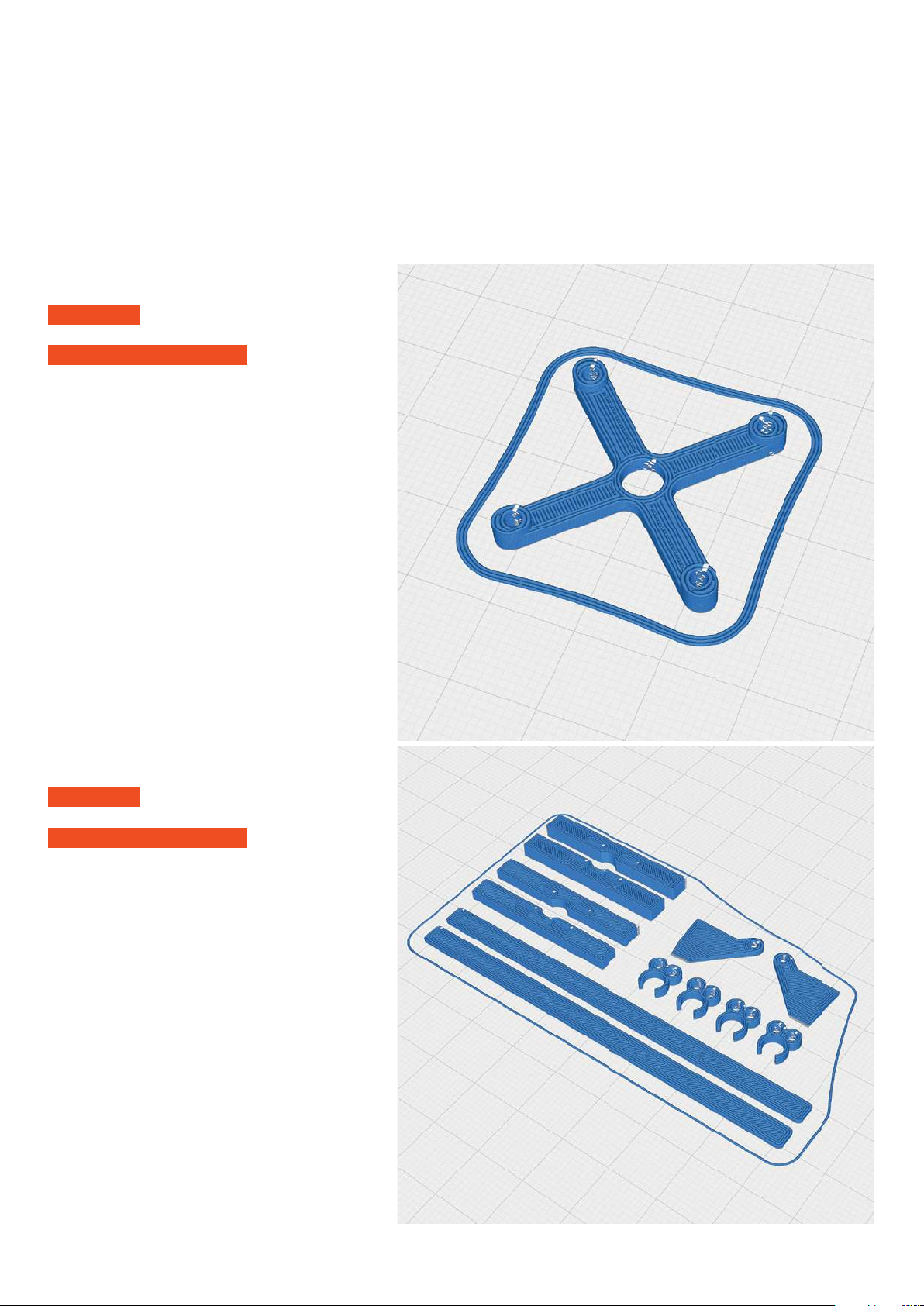
PROFILE P1_Fullbody
The following parts must be sliced with the PROFILE P1_Fullbody.
Please note the additional settings for the individual parts!
P1_Motormount-XXX_Rn.stl
MATERIAL PLA, Weight: ~ 1 g
ADDITIONAL SETTINGS
None required
PLA or Tough PLA
P1_Parts_Rn.stl
MATERIAL PLA, Weight: ~ 3 g
ADDITIONAL SETTINGS
None required
Page 6
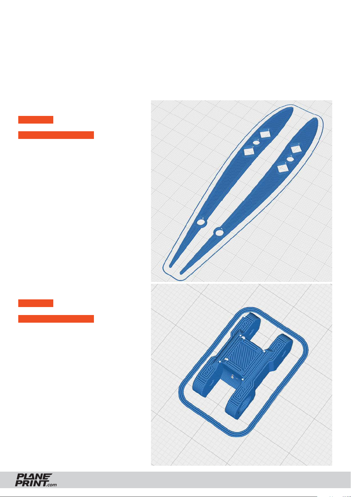
PROFILE P1_Fullbody
The following parts must be sliced with the PROFILE P1_Fullbody.
Please note the additional settings for the individual parts!
PLA or Tough PLA
P1_Protector_Rn.stl
MATERIAL PLA, Weight: ~ 3 g
ADDITIONAL SETTINGS
None required
P1_Spinner folding prop Xmm_Rn.stl
MATERIAL PLA, Weight: ~ 1 g
ADDITIONAL SETTINGS
None required
RISE NANO
PRINTING & ASSEMBLING MANUAL
© PLANEPRINT
6
Page 7
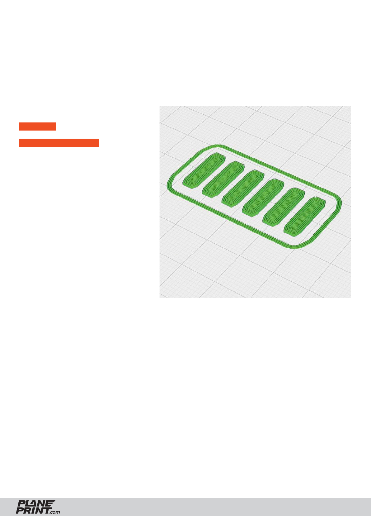
PROFILE P4_Flex
The following parts must be sliced with the PROFILE P4_Flex.
Please note the additional settings for the individual parts!
TPU A95
P4_Hinges_Rn.stl
MATERIAL TPU ~ A95, Weight: ~ 1 g
ADDITIONAL SETTINGS
None required
RISE NANO
PRINTING & ASSEMBLING MANUAL
© PLANEPRINT
7
Page 8
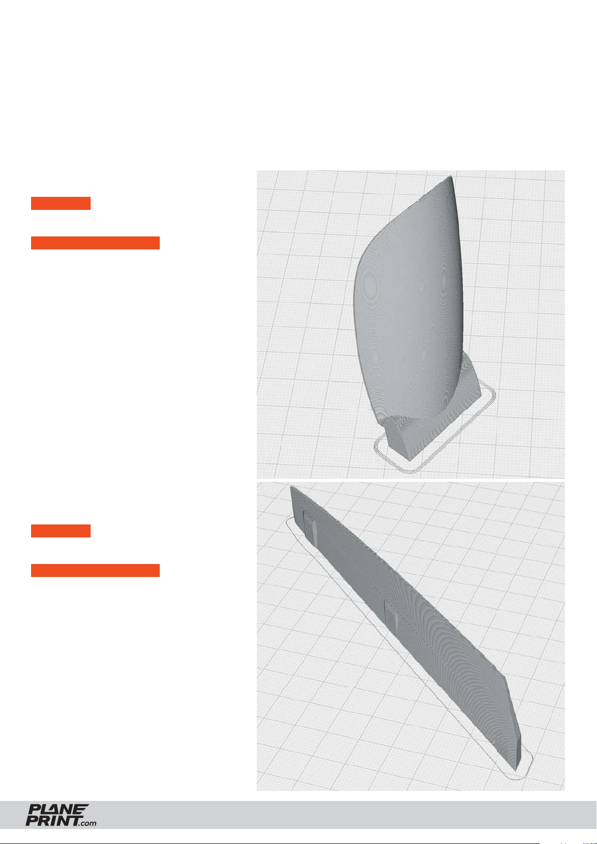
PROFILE P5_Gyroid
The following parts must be sliced with the PROFILE P5_Gyroid. Please note the additional settings
for the individual parts! It is essential to print these parts with LW-PLA!
Basic settings for LW-PLA: Please follow the instructions in our WINGTEST AND CALIBRATION TOOL
on our website for correct adjustment!
Light-Weight LW-PLA!
P5_Canopy_Rn.stl
MATERIAL LW-PLA, ~ 2 g*
*Weighed (approximate guideline)
ADDITIONAL SETTINGS
None required
P5_Elevator-L_Rn.stl and
P5_Elevator-R_Rn.stl
MATERIAL LW-PLA, ~ 2 g*
*Weighed (approximate guideline)
ADDITIONAL SETTINGS
None required
RISE NANO
PRINTING & ASSEMBLING MANUAL
© PLANEPRINT
8
Page 9
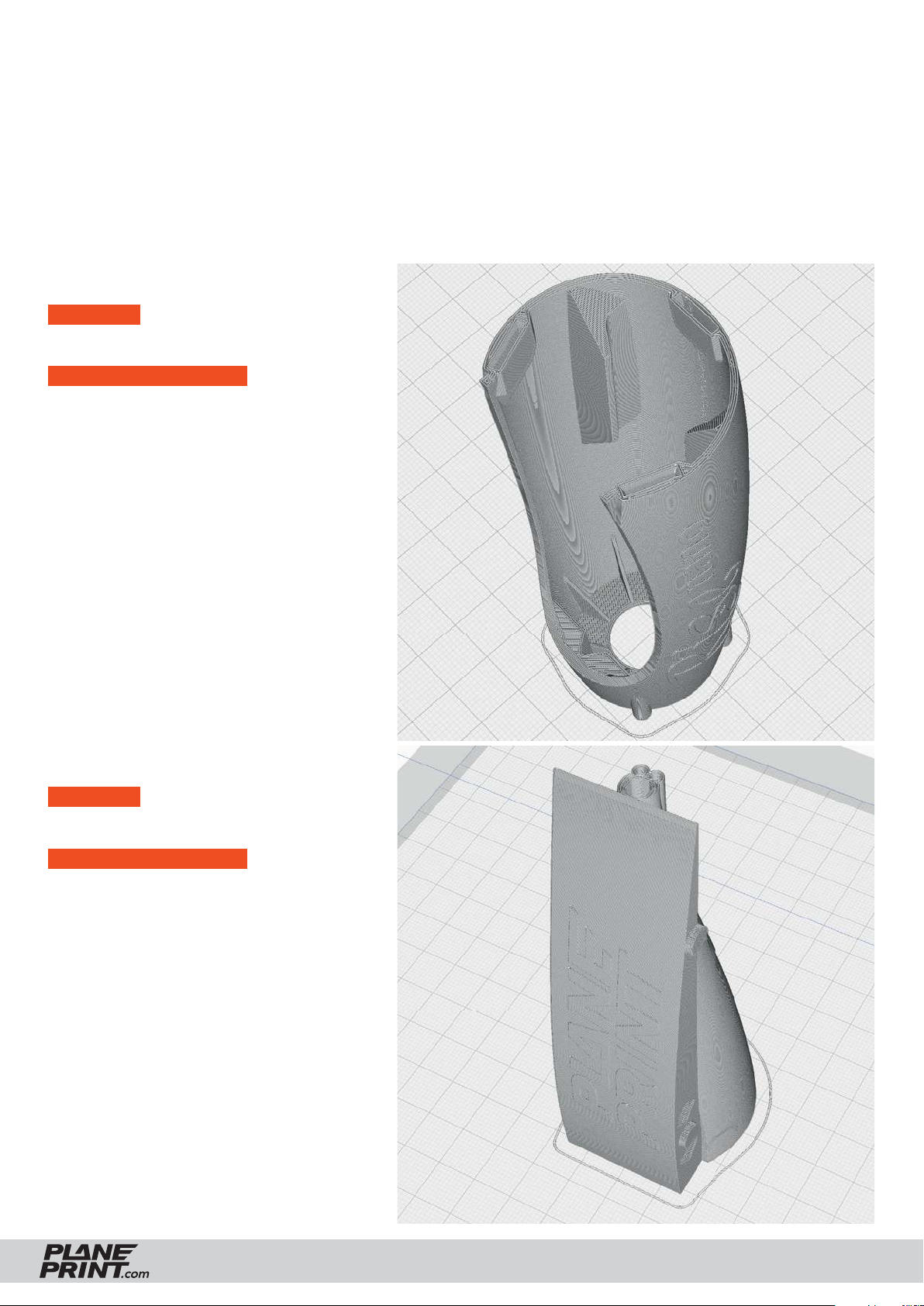
PROFILE P5_Gyroid
The following parts must be sliced with the PROFILE P5_Gyroid. Please note the additional settings
for the individual parts! It is essential to print these parts with LW-PLA!
Basic settings for LW-PLA: Please follow the instructions in our WINGTEST AND CALIBRATION TOOL
on our website for correct adjustment!
Light-Weight LW-PLA!
P5_Fuselage 1_Rn.stl
MATERIAL LW-PLA, ~ 6 g*
*Weighed (approximate guideline)
ADDITIONAL SETTINGS
None required
P5_Fuselage 2_Rn.stl
MATERIAL LW-PLA, ~ 7 g*
*Weighed (approximate guideline)
ADDITIONAL SETTINGS
None required
RISE NANO
PRINTING & ASSEMBLING MANUAL
© PLANEPRINT
9
Page 10
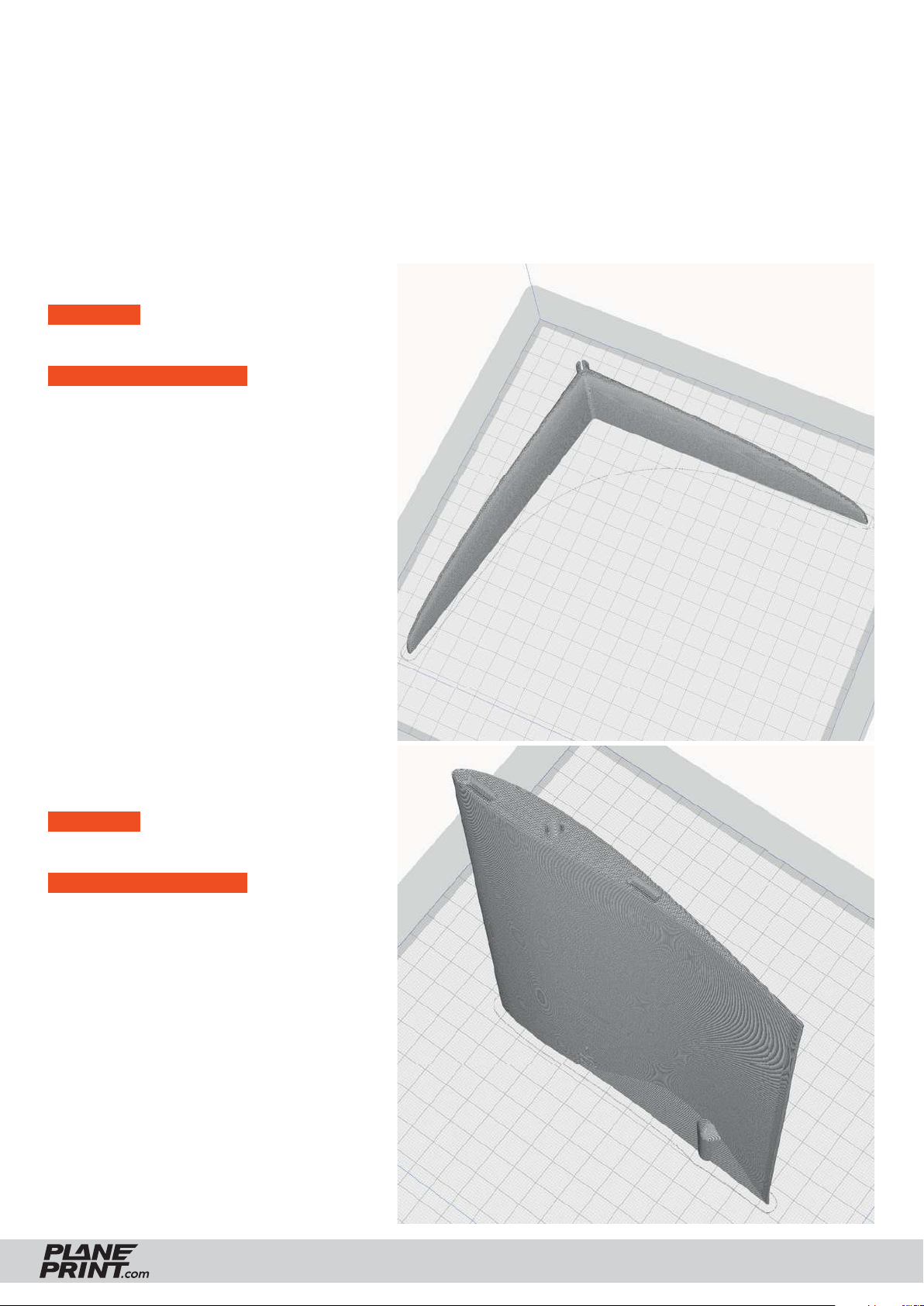
PROFILE P5_Gyroid
The following parts must be sliced with the PROFILE P5_Gyroid. Please note the additional settings
for the individual parts! It is essential to print these parts with LW-PLA!
Basic settings for LW-PLA: Please follow the instructions in our WINGTEST AND CALIBRATION TOOL
on our website for correct adjustment!
Light-Weight LW-PLA!
P5_V-Tail_Rn.stl
MATERIAL LW-PLA, ~ 8 g*
*Weighed (approximate guideline)
ADDITIONAL SETTINGS
• Z Seam Position: back left
P5_Wing 1-L_Rn.stl and
P5_Wing 1-R_Rn.stl
MATERIAL LW-PLA, ~ 20 g*
*Weighed (approximate guideline)
ADDITIONAL SETTINGS
None required
RISE NANO
PRINTING & ASSEMBLING MANUAL
© PLANEPRINT
10
Page 11
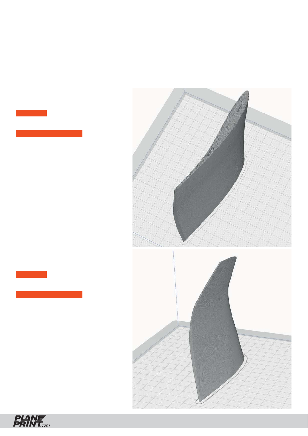
PROFILE P5_Gyroid
The following parts must be sliced with the PROFILE P5_Gyroid. Please note the additional settings
for the individual parts! It is essential to print these parts with LW-PLA!
Basic settings for LW-PLA: Please follow the instructions in our WINGTEST AND CALIBRATION TOOL
on our website for correct adjustment!
Light-Weight LW-PLA!
P5_Wing 2-L_Rn.stl and
P5_Wing 2-R_Rn.stl
MATERIAL LW-PLA, ~ 19 g*
*Weighed (approximate guideline)
ADDITIONAL SETTINGS
None required
P5_Wing 3-L_Rn.stl and
P5_Wing 3-R_Rn.stl
MATERIAL LW-PLA, ~ 8 g*
*Weighed (approximate guideline)
ADDITIONAL SETTINGS
None required
RISE NANO
PRINTING & ASSEMBLING MANUAL
© PLANEPRINT
11
Page 12
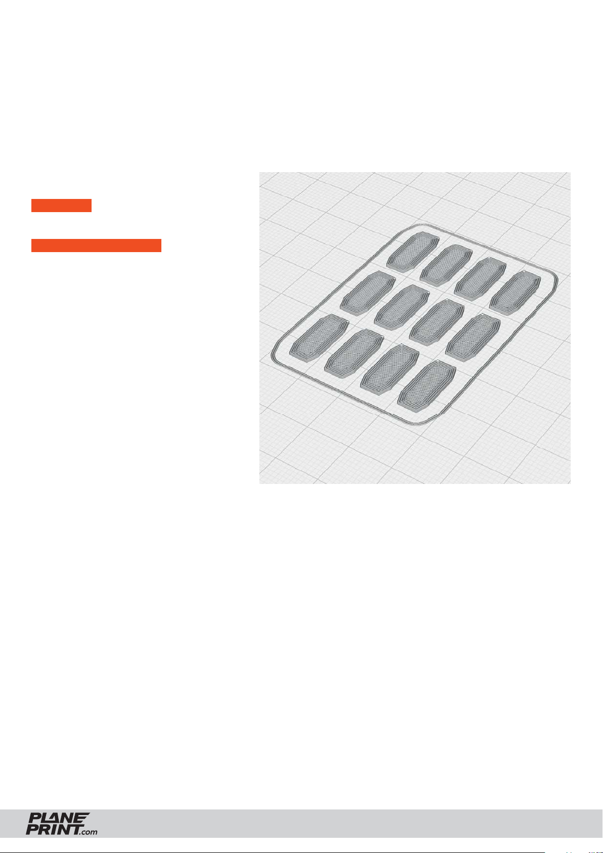
PROFILE P5_Gyroid Light-Weight LW-PLA!
The following parts must be sliced with the PROFILE P5_Gyroid. Please note the additional settings
for the individual parts! It is essential to print these parts with LW-PLA!
Basic settings for LW-PLA: Please follow the instructions in our WINGTEST AND CALIBRATION TOOL
on our website for correct adjustment!
P5_Interconnects_Rn.stl
MATERIAL LW-PLA, ~ 1 g*
*Weighed (approximate guideline)
ADDITIONAL SETTINGS
None required
RISE NANO
PRINTING & ASSEMBLING MANUAL
© PLANEPRINT
12
Page 13
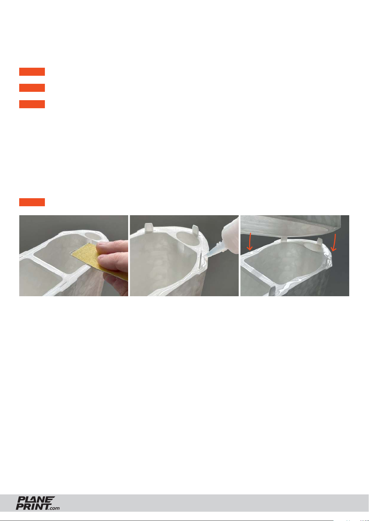
Basic Information:
Gluing the parts printed with PROFILE P5
STEP 1 As a first step, it is important to roughen and smooth the adhesive surfaces with sandpaper.
STEP 2 Insert the interconnects into the slots provided on one side.
STEP 3 Apply a lot of glue to the side with the interconnects. It is important that there is glue everywhere,
especially on the outside and inside of the wall surfaces, in order to achieve a perfect connection.
The interconnects only serve to align the parts to each other. It is better not to apply glue here,
otherwise it can happen that the glue suddenly hardens while the parts are being put together and
stops the process.
Use medium viscosity CA glue, thinner glue would run down the parts too easily.
After assembly, align the two parts exactly and wipe off the excess CA glue from the surface
with a cloth. Now spray with activator spray along the gluing surface and carefully press the parts
together.
STEP 4 Clean the glued areas slightly with a sharp-bladed cutter.
RISE NANO
PRINTING & ASSEMBLING MANUAL
© PLANEPRINT
13
Page 14
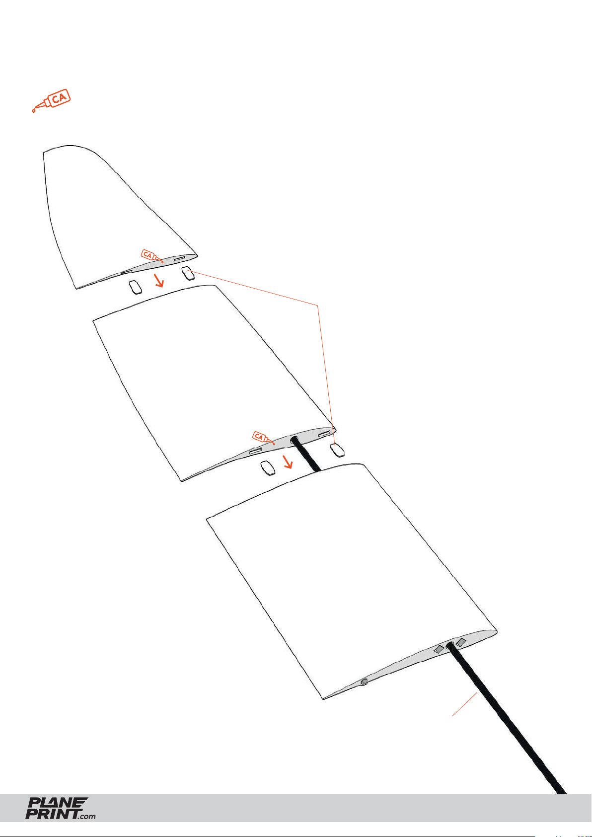
Wings assembly
Use the carbon rod for alignment
medium l.
P5_Wing 3-L_Rn.stl
but make sure that it is not glued!
P5_Interconnects_Rn.stl
P5_Wing 2-L_Rn.stl
P5_Wing 1-L_Rn.stl
RISE NANO
Carbon rod Ø4*580mm
(Do not glue!)
PRINTING & ASSEMBLING MANUAL
© PLANEPRINT
14
Page 15
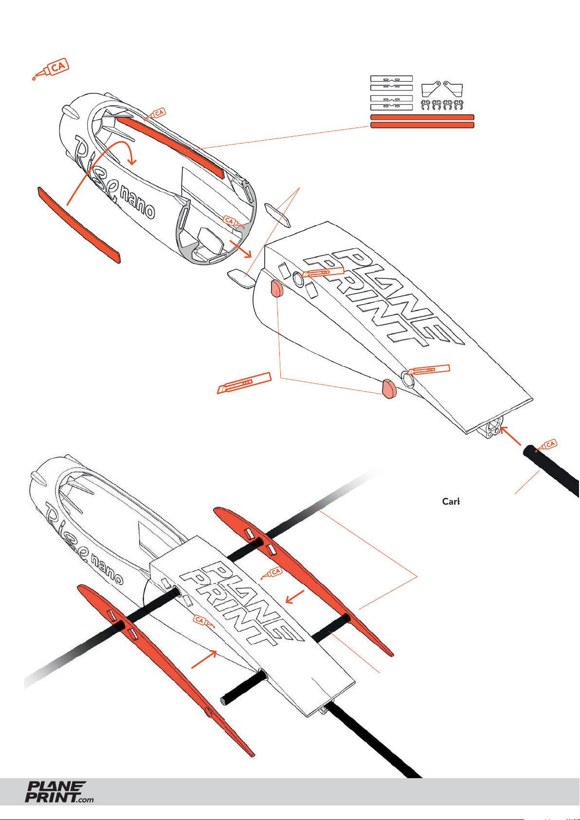
Fuselage assembly
medium l.
P1_Parts_Rn.stl
P5_Fuselage 1_Rn.stl
P1_Parts_Rn.stl
P5_Interconnects_Rn.stl
P5_Fuselage 2_Rn.stl
P1_Protector_Rn.stl
Remove support.
Please be careful with the knife!
Carbon rod Ø4*340mm
P1_Protector_Rn.stl
Use the carbon rods for
alignment but make sure
they are not glued along!
Carbon rod Ø4*80mm
(Do not glue!)
RISE NANO
PRINTING & ASSEMBLING MANUAL
© PLANEPRINT
15
Page 16
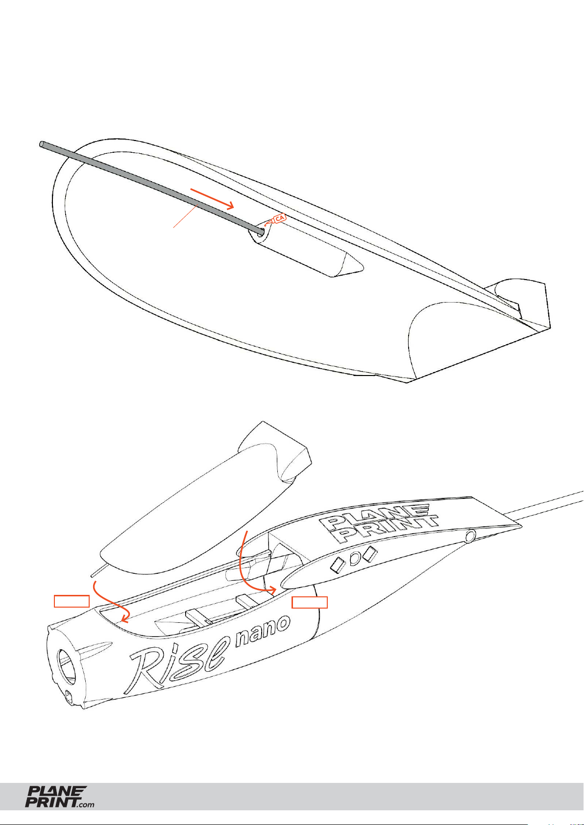
Canopy assembly
Steel wire Ø0.8*60mm
P5_Canopy_Rn.stl
STEP 1
RISE NANO
STEP 2
PRINTING & ASSEMBLING MANUAL
© PLANEPRINT
16
Page 17
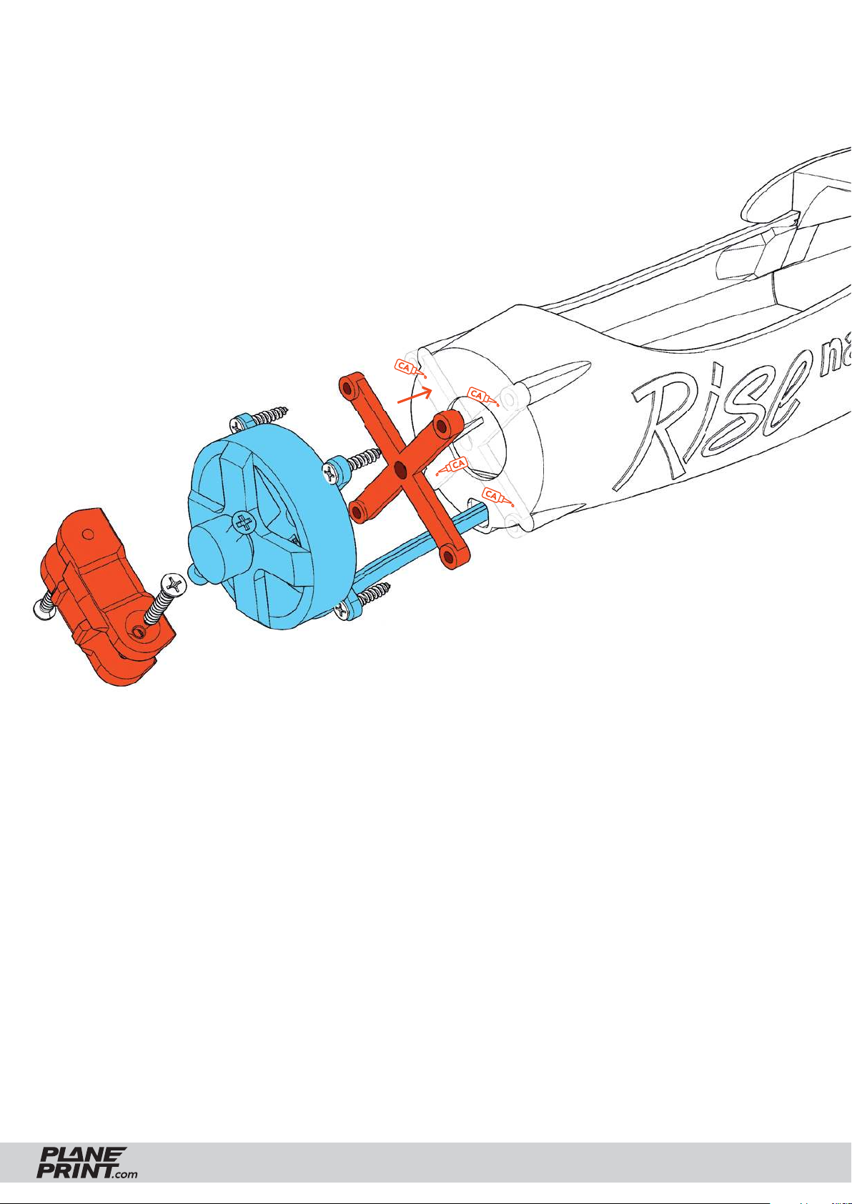
Motor mount
Tape the motor mount well to the fuselage and screw the motor on. Mount the folding
prop blades to the spinner, making sure they move easily but the screw is tight. Choose
the right width (6 or 8 mm) for your folding prop!
Then attach them with the rubber ring that comes with the motor (The spinner must be
very tight!). Normally the spinner fi ts exactly on a 5.5 mm shaft. If your motor is different,
this spinner must not be mounted. The prop must run absolutely accurate and
balanced! Always keep it away from you (and other people) when starting the motor!
P1_Spinner folding prop 6mm_Rn.stl
P1_Motormount-31mm_Rn.stl
RISE NANO
PRINTING & ASSEMBLING MANUAL
© PLANEPRINT
17
Page 18
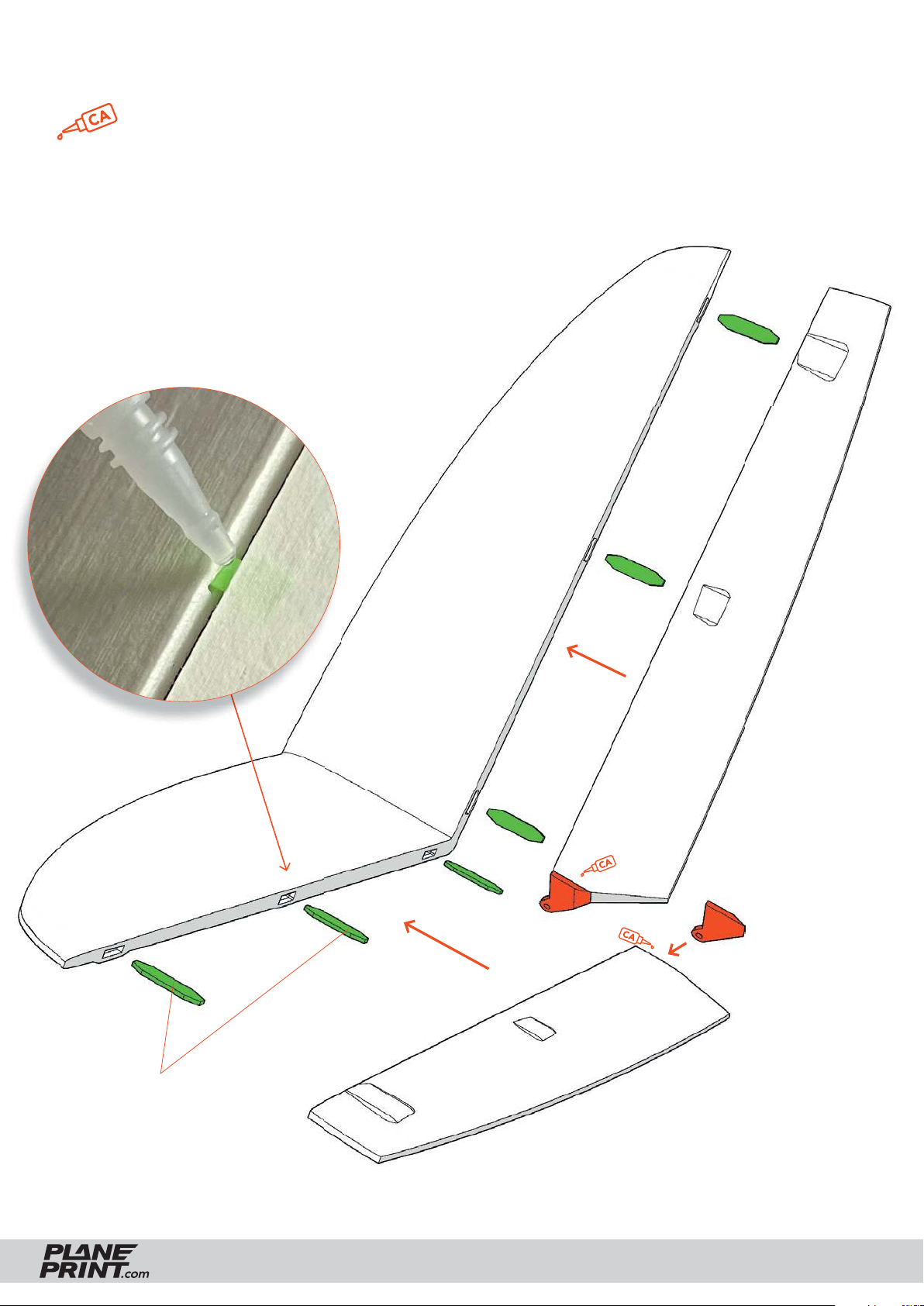
Tailplane assembly
thin liquid
Hinges: Put V-Tail, hinges and an elevator together and add a drop
of thin! CA glue on each hinge (photo). Due to the capillary effect,
the glue runs into the gaps. The distance between the V-tail and the
elevator must be large enough so that the elevator can be rotated by
about 45° (about 1.5 mm gap in neutral position).
Important: There must not be too much glue on the hinge and
the elevator must move easily.
P5_V-Tail_Rn.stl
P5_Elevator-R_Rn.stl
P1_Parts_Rn.stl
P5_Elevator-L_Rn.stl
P4_Hinges_Rn.stl
RISE NANO
PRINTING & ASSEMBLING MANUAL
© PLANEPRINT
18
Page 19
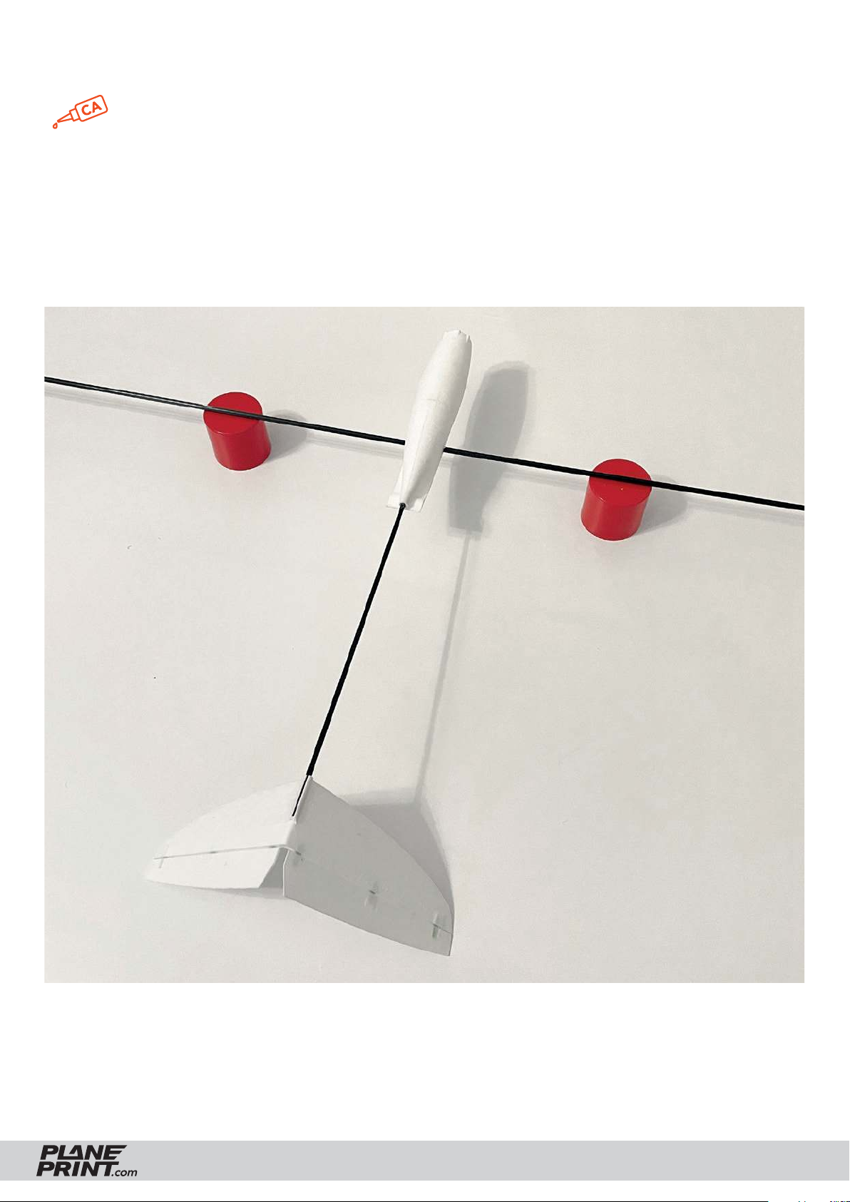
Tailplane assembly
thin liquid
Insert the carbon rod for the wing into the fuselage and place it upside
down on two supports of the same height so that it is absolutely parallel
to the ground (in this case, caps from activator spray cans). Then place
the V-tail on the rear carbon rod. When the V-tail rests on the table, it is
automatically in the correct position relative to the fuselage. Then put
thin CA glue in the gap of the carbon rod.
RISE NANO
PRINTING & ASSEMBLING MANUAL
© PLANEPRINT
19
Page 20
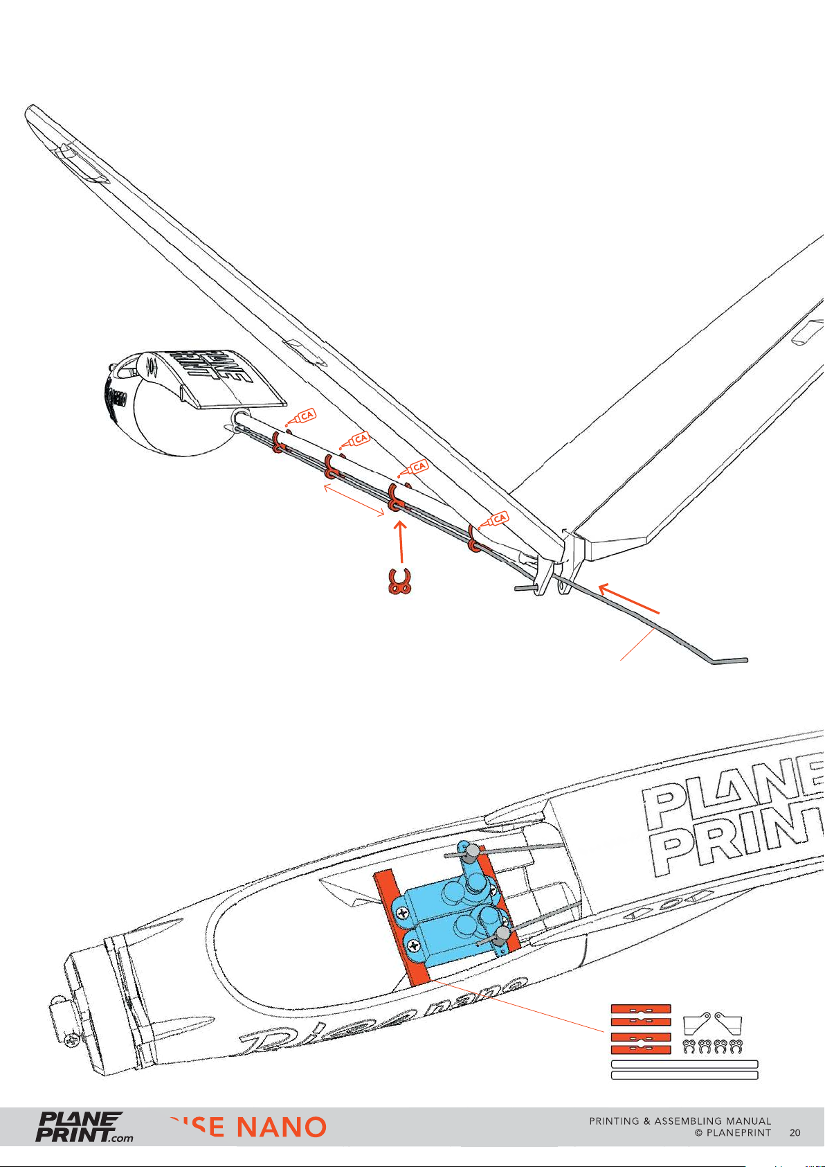
Linkage
Clip the linkage clamps to the Carbon rod as shown.
The rear one comes directly to the V-tail, the others have
a distance of 65 mm each. Align them exactly downwards
and glue them without putting glue in the small holes.
Bend the two steel wires by 90° and guide them from
behind into the clamps and into the fuselage.
Make sure that the wire moves very smoothly.
65 mm
P1_Parts_Rn.stl
Servo mount
The servos must sit as low as possible in the fuselage.
There are two different servo holders in different heights,
suitable for different servos.
Steel wire Ø0.8*450mm
(better a little longer, it can then
be shortened at the front later).
RISE NANO
P1_Parts_Rn.stl
PRINTING & ASSEMBLING MANUAL
© PLANEPRINT
20
Page 21
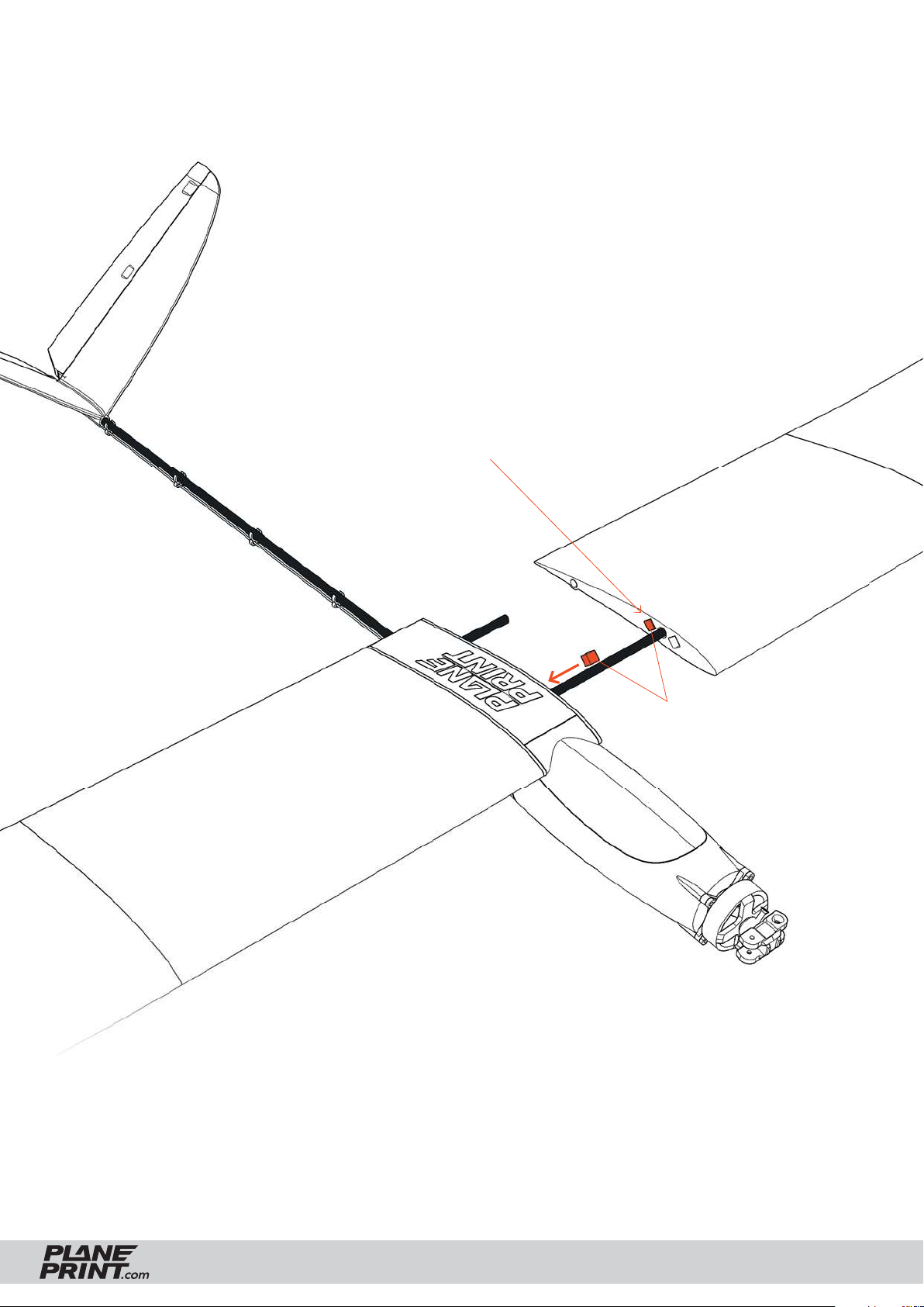
Wing mount
Glue the magnets into the gaps and the
counterparts into the fuselage.
Pay attention to the alignment of the
magnets to each other!
One magnetic connection per side is
suffi cient, if you want it to be particularly
strong, you can place a second magnet in
front of the carbon rod.
Neodym Super
Magnets 5x5x5 mm
RISE NANO
PRINTING & ASSEMBLING MANUAL
© PLANEPRINT
21
Page 22
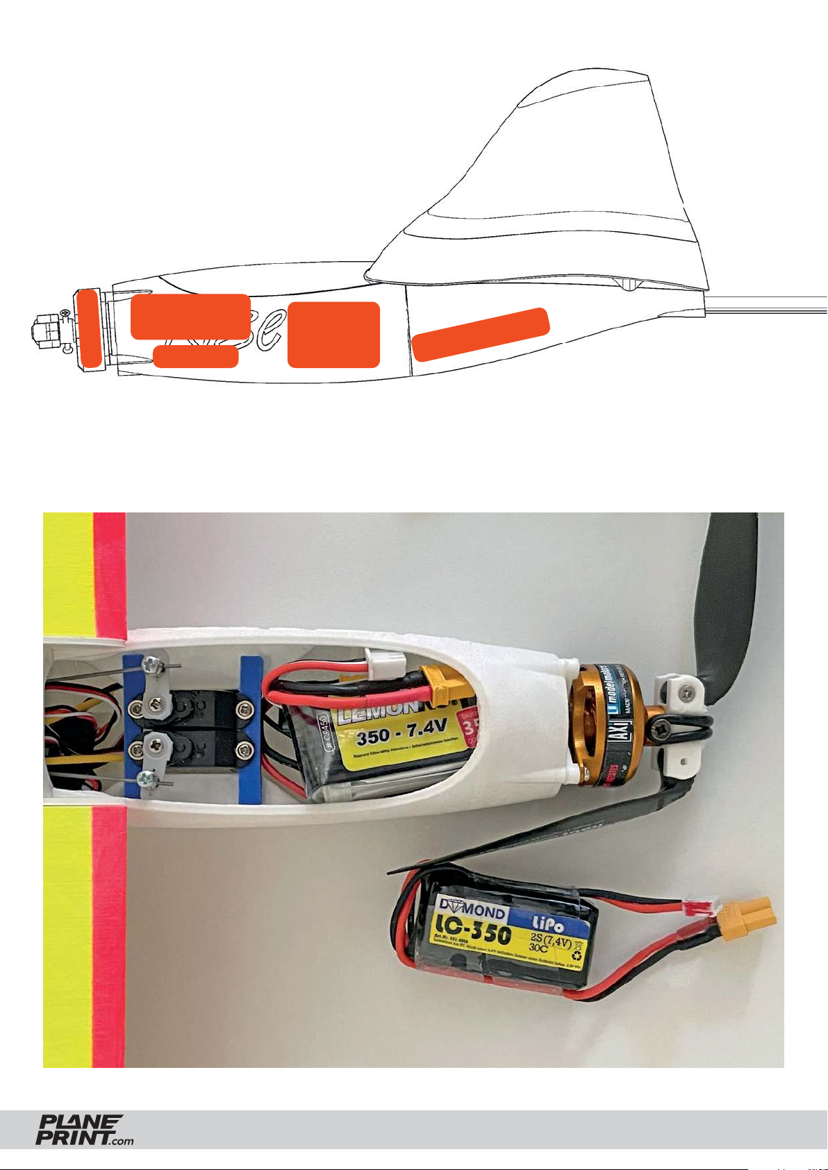
RC components
Battery
Motor
Controller
Servos
Receiver
RISE NANO
PRINTING & ASSEMBLING MANUAL
© PLANEPRINT
22
Page 23
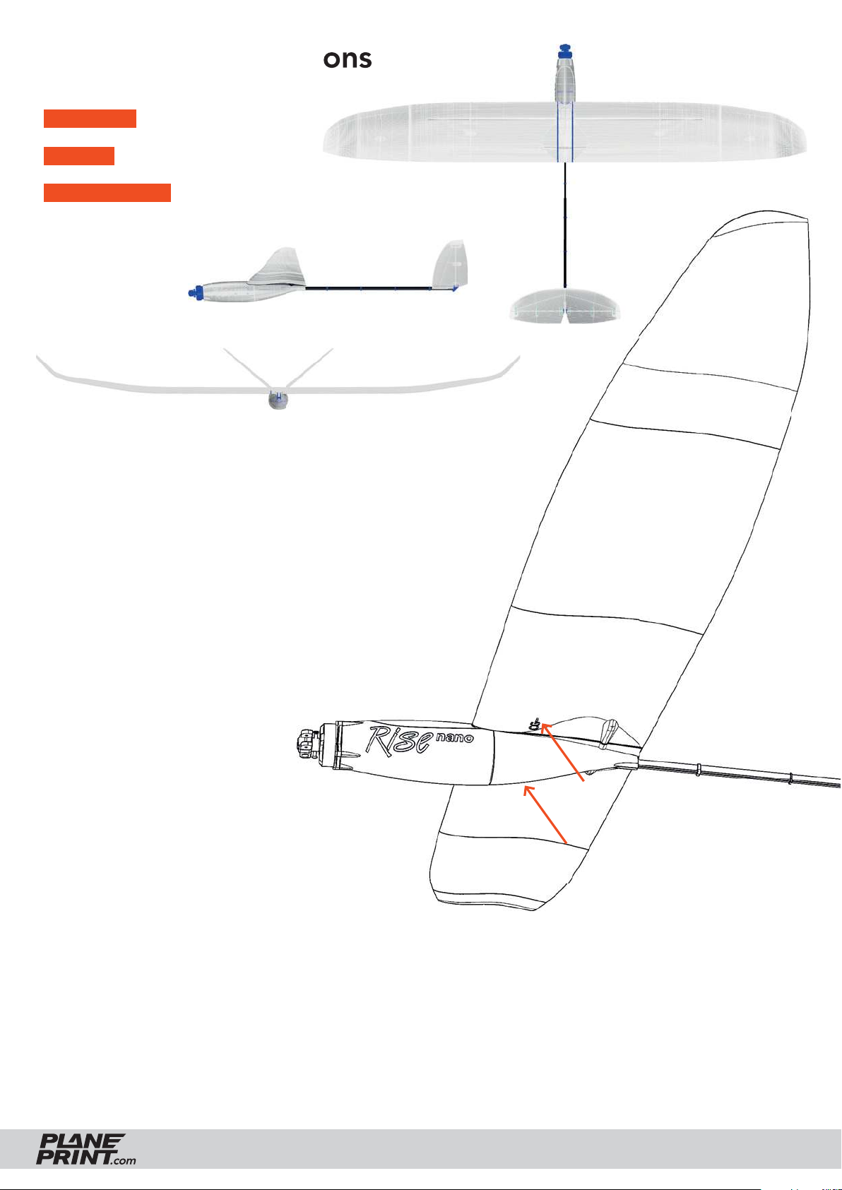
Technical specifi cations
WINGSPAN 1020 mm/40 inches
LENGTH 590 mm/23 inches
FLIGHT WEIGHT 240 grams
Center of Gravity (CG)
The aircraft must balance precisely on these points.
Do not forget to check if the wings are exactly
in ballance in the roll axis. If one wing is heavier,
correct this with a small weight on the wingtip.
Flying tips
The RISE nano is controlled by elevator and rudder only and has no ailerons. However, it is recommended
to use the rudder function in parallel on both control sticks (rudder and aileron). To do this, simply mix the
aileron stick with the rudder stick.
The RISE nano has a wide speed range, which means you can fl y it very fast or relatively slow. In thermal
conditions, the elevator should be trimmed up a few clicks to climb optimally in the updraft. You can also
program two fl ight phases for this.
RISE NANO
PRINTING & ASSEMBLING MANUAL
© PLANEPRINT
23
Page 24
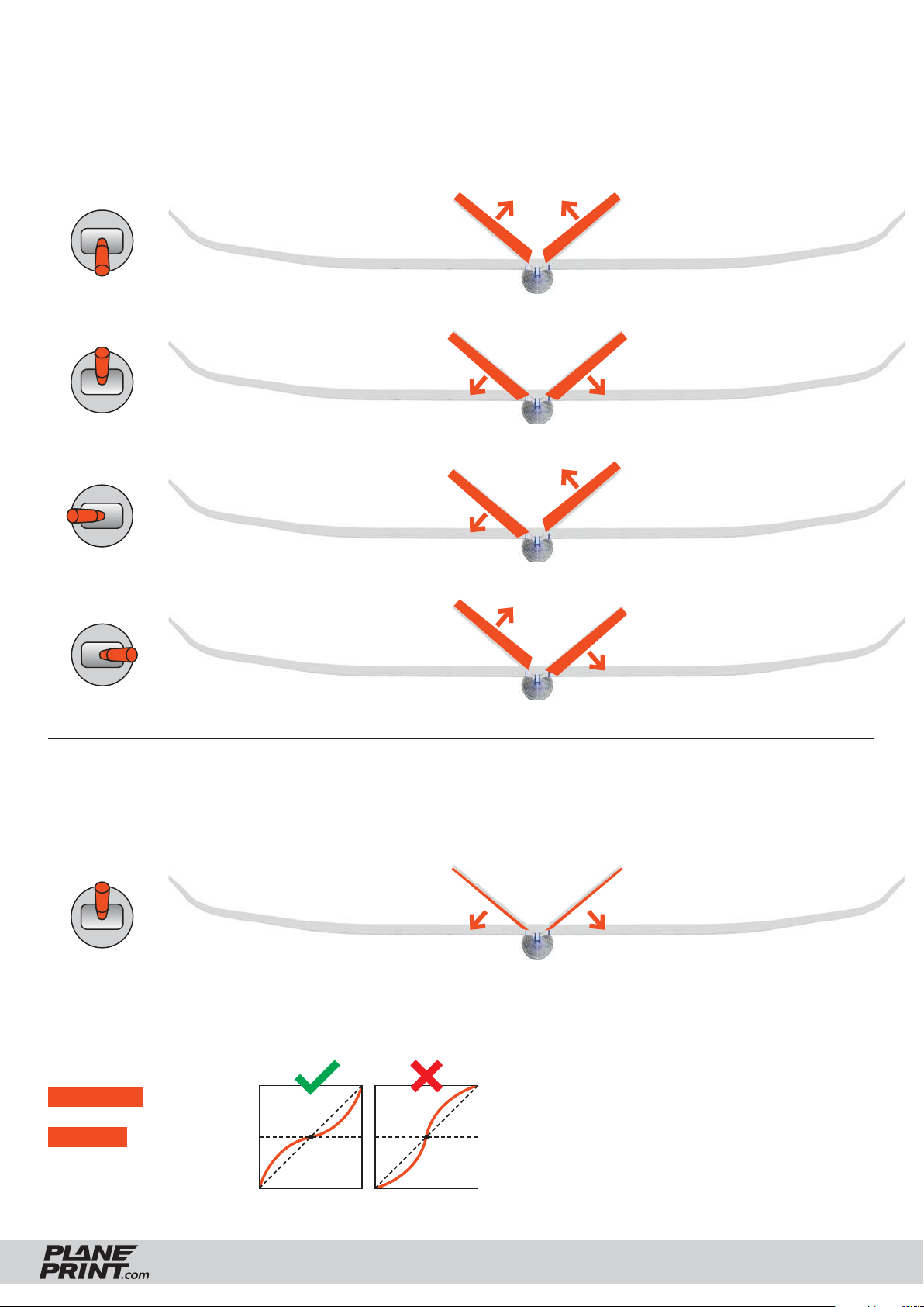
Settings for fl ying
When checking the control directions, look at the aircraft from behind.
Elevator up
+ 10 mm up + 10 mm up
Elevator down
+ 10 mm down
+ 10 mm down
Rudder left
+ 10 mm down
+ 10 mm up
Rudder right
+ 10 mm up + 10 mm down
At full throttle the nose pulls up a bit, to avoid this you can mix some elevator down to the trottle (about 10%).
But do not test this at the fi rst start but at high altitude!
Full Throttle
Expo setting
ELEVATOR 20 %
RUDDER 20 %
RISE NANO
~ 10 % down ~ 10 % down
(for some remote
controls a minus
has to be in front
of the number)
PRINTING & ASSEMBLING MANUAL
© PLANEPRINT
24
Page 25

AGE RECOMMENDATION 14+
NOT FOR CHILDREN UNDER 14 YEARS.
THIS IS NOT A TOY!
The STL data (or data processed from it, such as G codes)
must never be passed on to third parties!
The purchase of the STL does not authorize the production
of models for third parties.
By using the download data, an RC model airplane, called
„model“ for short, can be manufactured using a 3D printer.
As a user of this model, only you are responsible for safe
operation that does not endanger you or others, or that
does not damage the model or property of others.
PLANEPRINT.com assumes no responsibility for damage to
persons and property caused by pressure, transport or use
of the product. Filaments, printing supplies, hardware or
consumables that can not be used after faulty 3D printing
will not be replaced by PLANEPRINT.com in any way.
When operating, always keep a safe distance from your
model in all directions to avoid collisions and injuries.
This model is controlled by a radio signal. Radio signals can
be disturbed from outside without being able to influence
it. Interference can lead to a temporary loss of control.
Always operate your model on open terrains, far from cars,
traffic and people.
Keep all chemicals, small parts and electrical components
out of the reach of children.
Avoid water contact with all components that are not specially
designed and protected. Moisture damages the electronics.
Never take an item of the model or accessory in your mouth
as this can lead to severe injuries or even death.
Never operate your model with low batteries in the transmitter or model.
Always keep the model in view and under control.
Use only fully charged batteries.
Always keep the transmitter switched on when the model
is switched on.
Always remove the battery before disassembling the model.
Keep moving parts clean and dry at all times.
Always allow the parts to cool before touching them.
Always remove the battery after use.
Make sure that the Failsafe is properly set before the flight.
Always follow the instructions and warnings for this product
and any optional accessories (servos, receivers, motors,
propellers, chargers, rechargeable batteries, etc.) carefully.
We develop our models to the best of our knowledge and belief.
We accept no liability for consequential damage and injuries
caused by improper use or incorrectly printed parts. Please be
careful when handling motors, batteries and propellers and
only move your model with insurance and in approved places!
Never operate the model with damaged wiring.
Never touch moving parts.
© PLANEPRINT.com, A-6021 Innsbruck, Conradstraße 6, [email protected]
© Design STL files by René Marschall • Layout: marschall designlab, marschall.cc
 Loading...