

Page 1
Flying wing for slope and coast fl ying
www.planeprint.com
the ONLY place where you can get
original Planeprint STL fi les legally!
PRINTING & ASSEMBLING MANUAL
Page 2
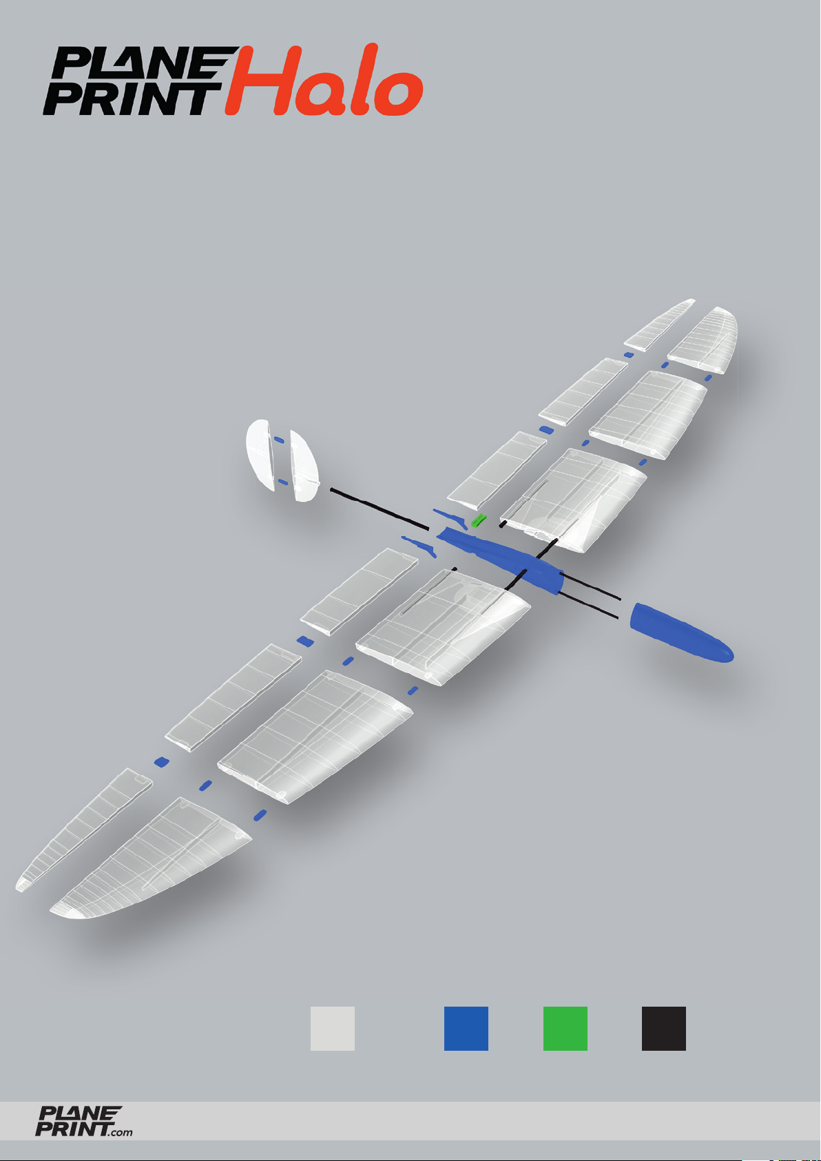
PLA TPULW-PLA CARBON
HALO
PRINTING & ASSEMBLING MANUAL
© PLANEPRINT
2
Page 3
RC Components
RECEIVER 2 Channel
BATTERY If you use high voltage servos you can use a small 2S/350 mAh Lipo battery,
otherwise a receiver battery (size maximum 50x27x17mm)
SERVOS 2 Nano Servos (8 mm thick, maximum 9 mm) for example:
• CHASERVO D S 06 high voltage (fits perfectly)
• Hitec HS 40 Eco Servo 4,8g
Required accessoires – basic equipment
• LW-PLA (cannot be replaced by PLA or pre-foamed LW), ~190 grams
• PLA or Tough PLA, ~50 grams
• TPU A95, ~10 grams (Can be replaced by LW-PLA)
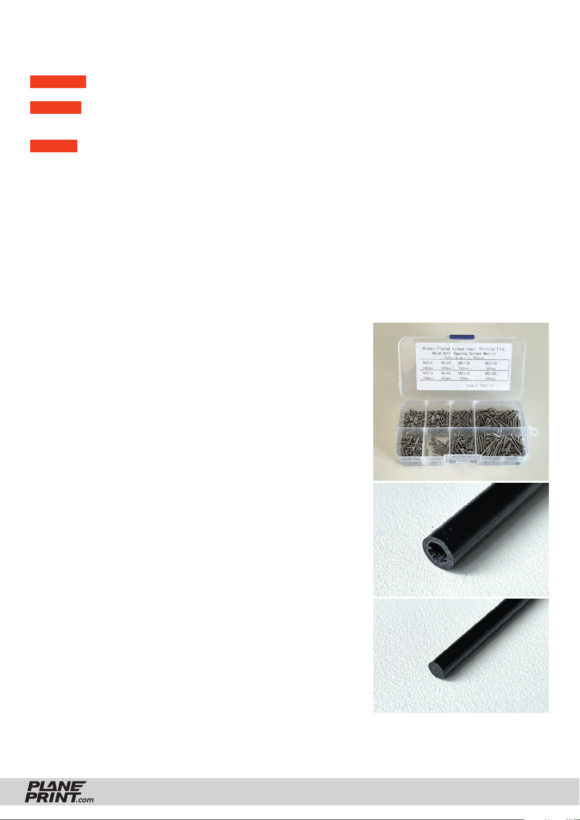
• some tapping screws Ø2mm
• CA super glue (liquid and medium)
• CA activator
• Carbon tube Ø5*1000mm, 1 piece
• Carbon rod Ø3*1000mm, 1 piece
• Steel wire Ø0.8*100mm (Ø1 also possible), 2 pieces
• UHU POR glue (or another handicraft glue)
• Fabric tape for the aileron hinges
• some lead
Tools
• Cutter knife
• Drill Ø1.5mm
• small Phillips screwdriver
• Metal saw
• Side cutter
• Needle nose pliers
Tapping screws Ø2mm
Carbon tube
Carbon rod
HALO
PRINTING & ASSEMBLING MANUAL
© PLANEPRINT
3
Page 4
The development of a complex, airworthy RC flight model to express on any standard 3D printer is a very extensive process. Therefore, we appeal to your fairness
not to forward the STL data you have acquired to third parties.
Thank you for your understanding and have fun with your PLANEPRINT MODEL!
Printing the parts – Printing profiles
This manual is constantly being improved and supplemented, we recommend
downloading the latest version from our website before building.
To print all PLANEPRINT models you need to set some basic profiles in Cura
(If you use another slicer, please set the same parameters).
You can find the description at www.planeprint.com/print
For this model you need the following profiles:
HALO
PRINTING & ASSEMBLING MANUAL
© PLANEPRINT
4
Page 5
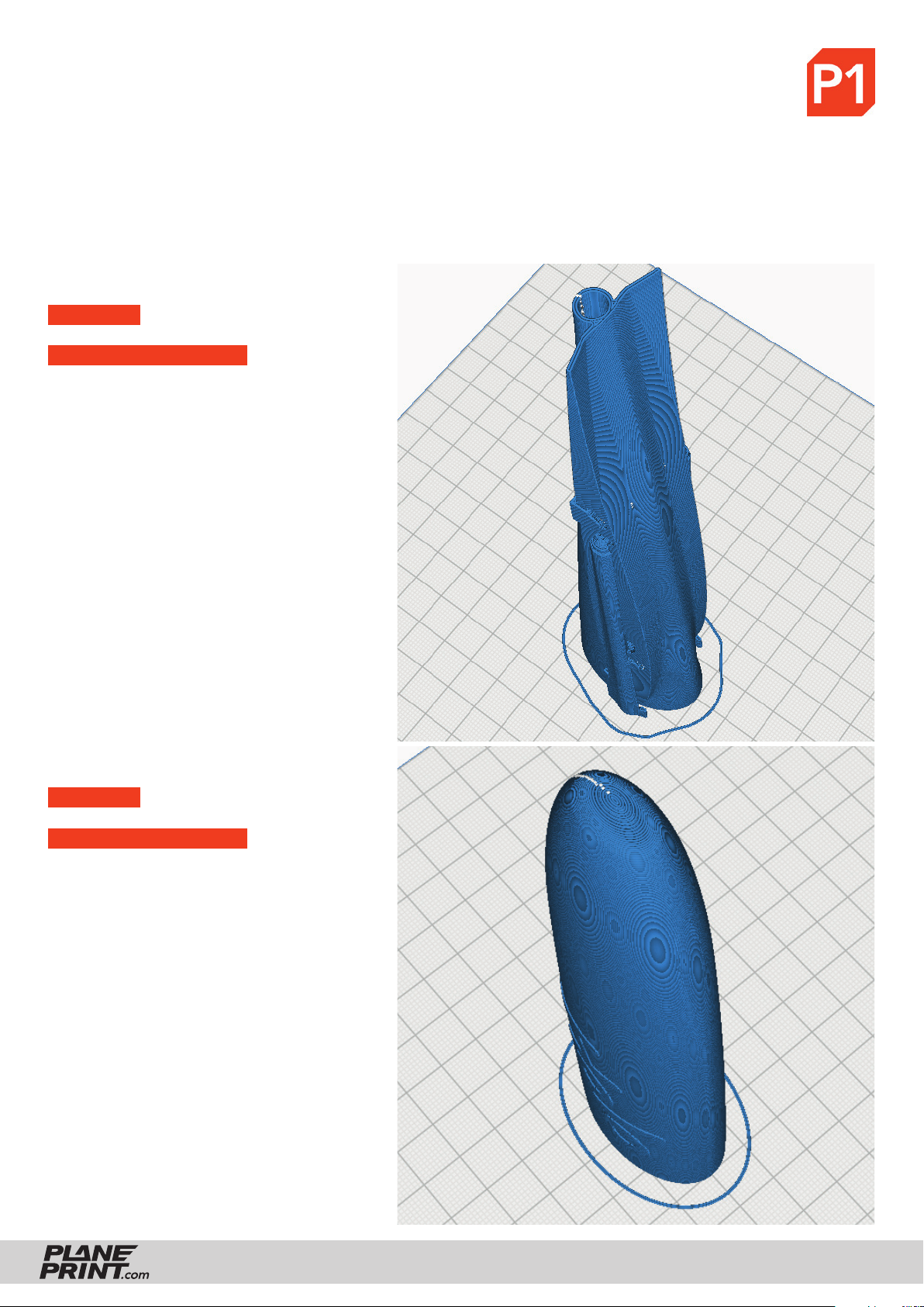
PROFILE P1_Fullbody Tough PLA or PLA
The information about the basic settings you can fi nd on our website at PRINT.
Please note the additional settings for the individual parts!
P1_Fuselage_halo.stl
MATERIAL PLA, Weight: ~ 18 g (without support)
ADDITIONAL SETTINGS
• Wall Line Count/Perimeters: 1
• Infi ll Density/Fill Density: 6 %
• Infi ll Pattern/Fill Pattern: Gyroid
• set Support
P1_Nose_halo.stl
MATERIAL PLA, Weight: ~ 19 g
ADDITIONAL SETTINGS
None required
HALO
PRINTING & ASSEMBLING MANUAL
© PLANEPRINT
5
Page 6
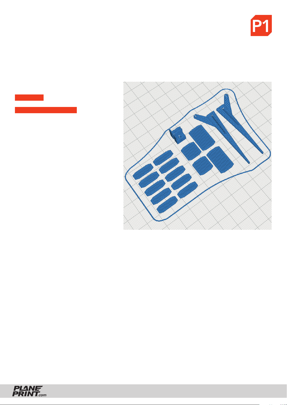
PROFILE P1_Fullbody Tough PLA or PLA
The information about the basic settings you can fi nd on our website at PRINT.
Please note the additional settings for the individual parts!
P1_Parts_halo.stl
MATERIAL PLA, Weight: ~ 4 g
ADDITIONAL SETTINGS
None required
HALO
PRINTING & ASSEMBLING MANUAL
© PLANEPRINT
6
Page 7
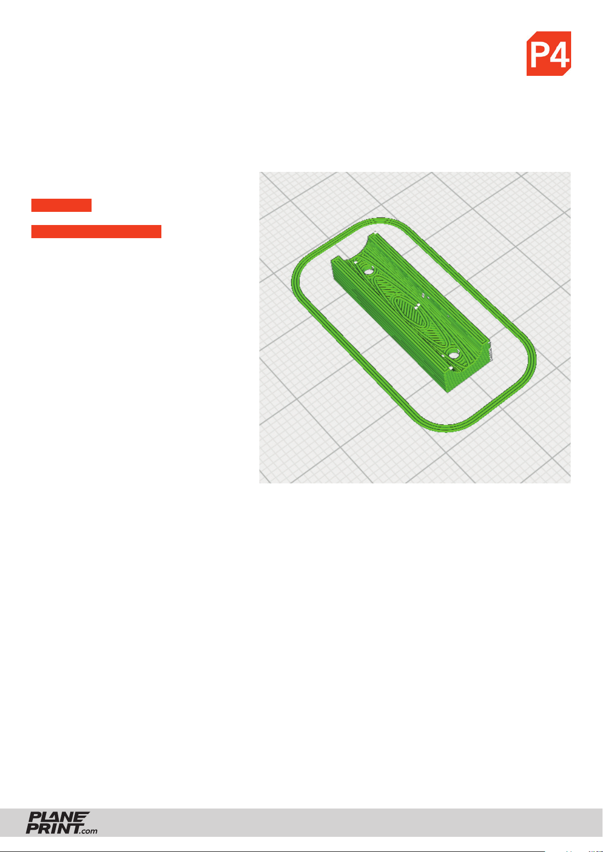
PROFILE P4_Flex TPU A95
The information about the basic settings you can fi nd on our website at PRINT.
Please note the additional settings for the individual parts!
P4_Wing mount_halo.stl
MATERIAL TPU A95, Weight: ~ 1 g
ADDITIONAL SETTINGS
• Infi ll Density: 100 %
HALO
PRINTING & ASSEMBLING MANUAL
© PLANEPRINT
7
Page 8
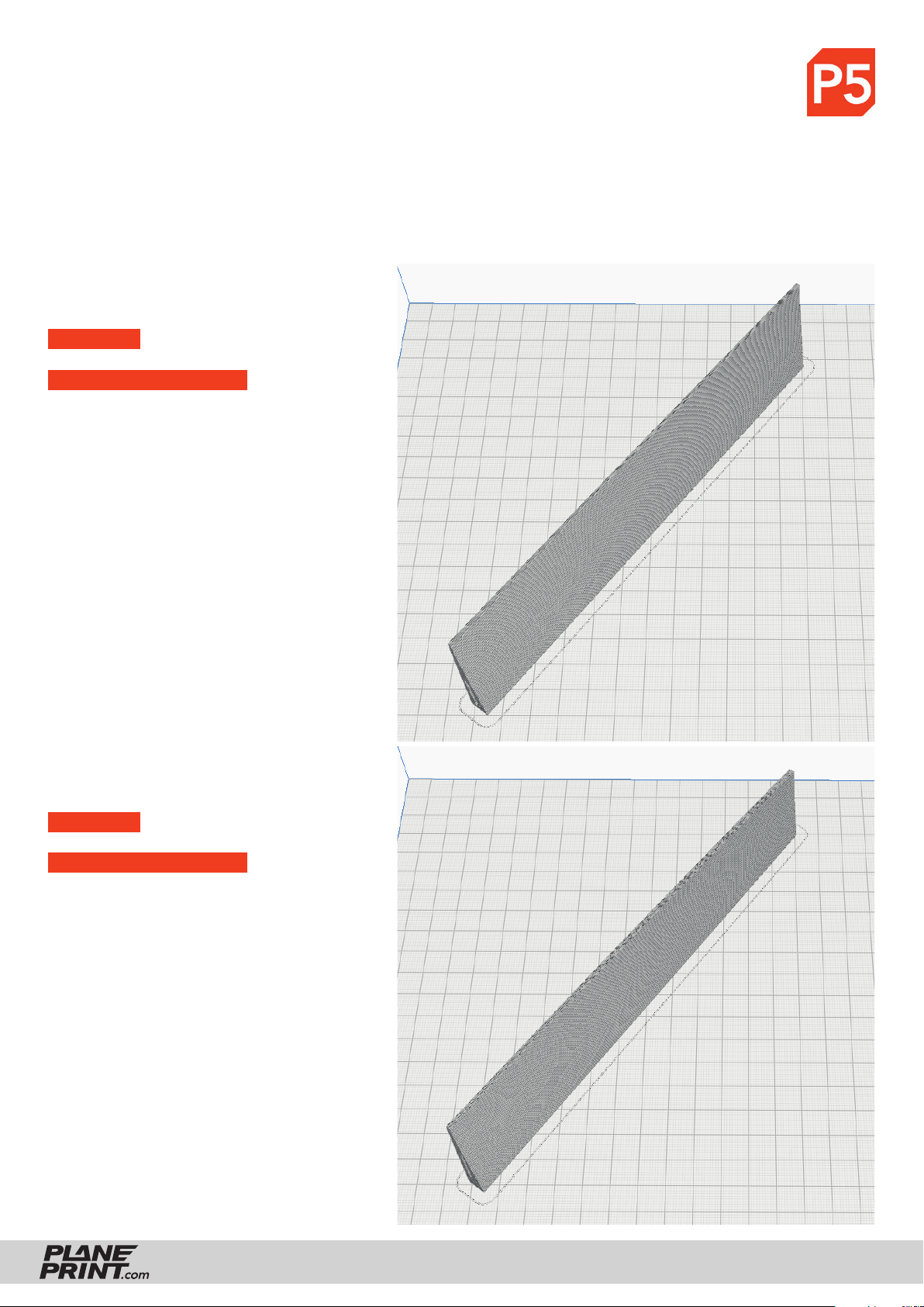
PROFILE P5_Gyroid Light-Weight LW-PLA!
The information about the basic settings you can fi nd on our website at PRINT.
Please note the additional settings for the individual parts!
It is essential to print these parts with LW-PLA!
Basic settings for LW-PLA: Please follow the instructions in our WINGTEST AND CALIBRATION TOOL on our
website for correct adjustment! For optimum quality, there should only ever be one part on the build plate!
P5_Aileron L 1_halo.stl and
P5_Aileron R 1_halo.stl
MATERIAL LW PLA, Weight: ~ 7 g
ADDITIONAL SETTINGS
• Infi ll Density/Fill Density: 4 %
P5_Aileron L 2_halo.stl and
P5_Aileron R 2_halo.stl
MATERIAL LW PLA, Weight: ~ 7 g
ADDITIONAL SETTINGS
• Infi ll Density/Fill Density: 4 %
HALO
PRINTING & ASSEMBLING MANUAL
© PLANEPRINT
8
Page 9
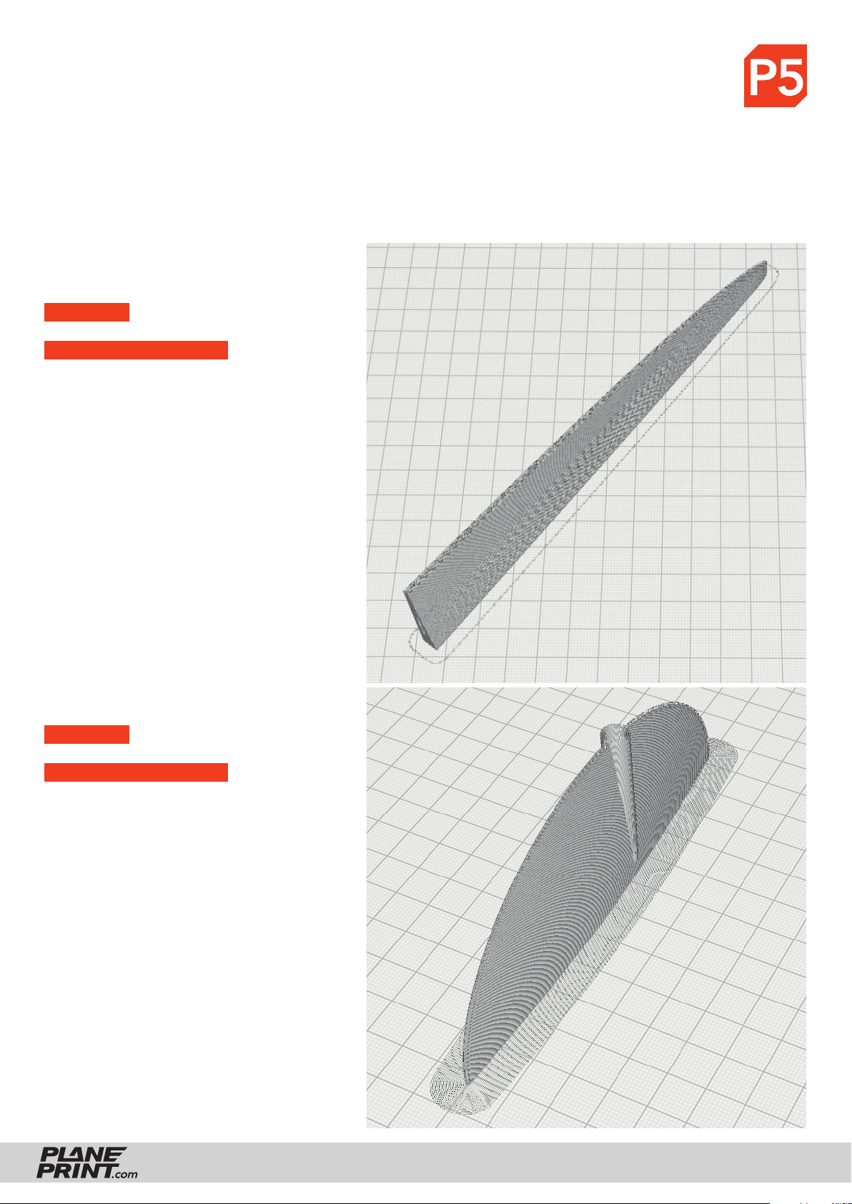
PROFILE P5_Gyroid Light-Weight LW-PLA!
The information about the basic settings you can fi nd on our website at PRINT.
Please note the additional settings for the individual parts!
It is essential to print these parts with LW-PLA!
Basic settings for LW-PLA: Please follow the instructions in our WINGTEST AND CALIBRATION TOOL on our
website for correct adjustment! For optimum quality, there should only ever be one part on the build plate!
P5_Aileron L 3_halo.stl and
P5_Aileron R 3_halo.stl
MATERIAL LW PLA, Weight: ~ 4 g
ADDITIONAL SETTINGS
• Infi ll Density/Fill Density: 4 %
P5_Rudder 1_halo.stl
MATERIAL LW PLA, Weight: ~ 4 g
ADDITIONAL SETTINGS
• Infi ll Density/Fill Density: 4 %
• set Brim
HALO
PRINTING & ASSEMBLING MANUAL
© PLANEPRINT
9
Page 10
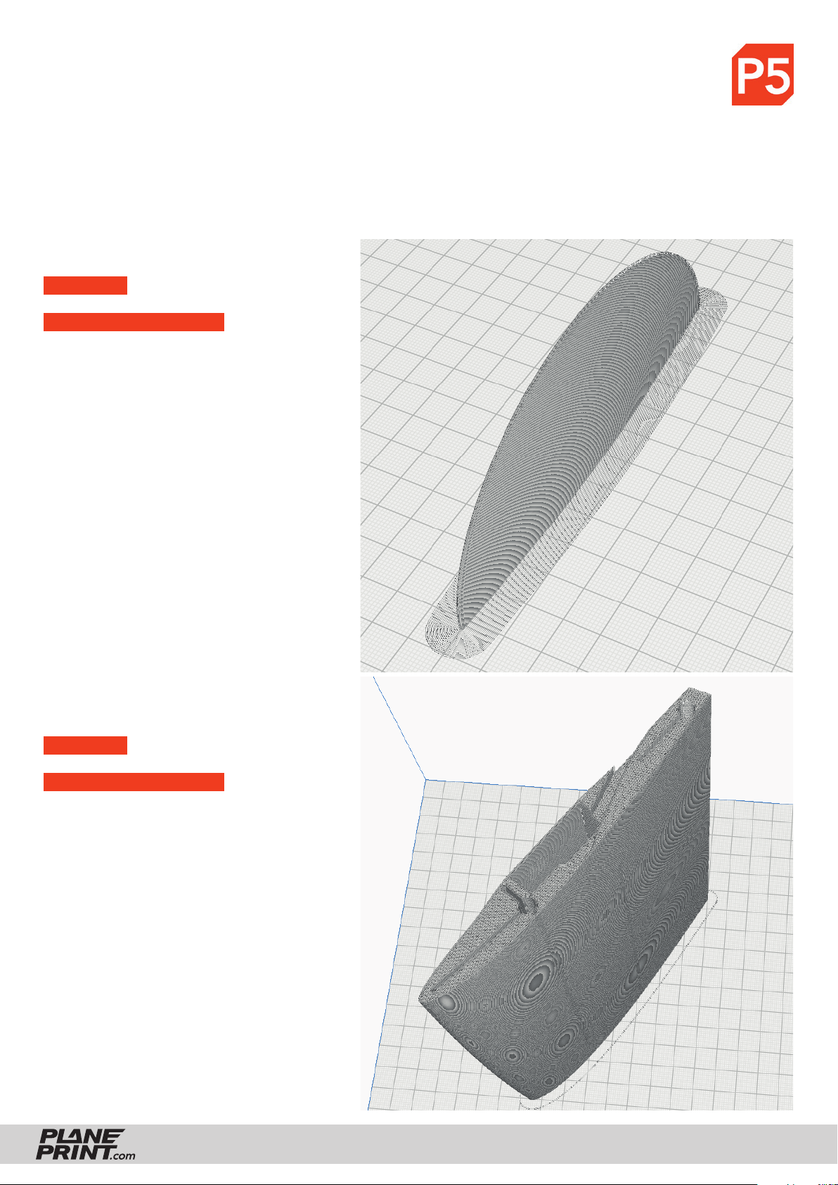
PROFILE P5_Gyroid Light-Weight LW-PLA!
The information about the basic settings you can fi nd on our website at PRINT.
Please note the additional settings for the individual parts!
It is essential to print these parts with LW-PLA!
Basic settings for LW-PLA: Please follow the instructions in our WINGTEST AND CALIBRATION TOOL on our
website for correct adjustment! For optimum quality, there should only ever be one part on the build plate!
P5_Rudder 2_halo.stl
MATERIAL LW PLA, Weight: ~ 4 g
ADDITIONAL SETTINGS
• Infi ll Density/Fill Density: 4 %
• set Brim
P5_Wing L 1_halo.stl and
P5_Wing R 1_halo.stl
MATERIAL LW PLA, Weight: ~ 33 g
ADDITIONAL SETTINGS
• Infi ll Density/Fill Density: 4 %
HALO
PRINTING & ASSEMBLING MANUAL
© PLANEPRINT
10
Page 11
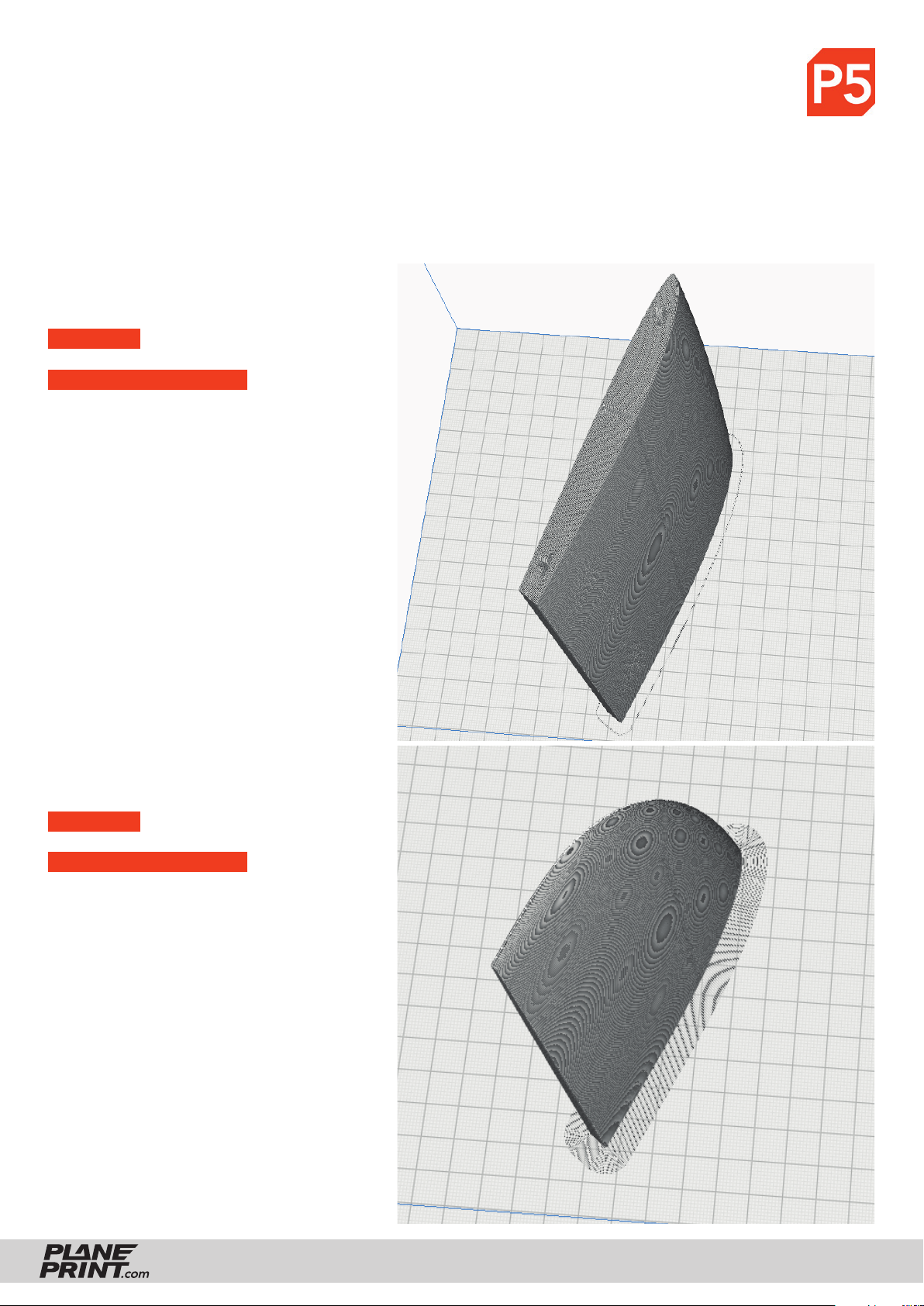
PROFILE P5_Gyroid Light-Weight LW-PLA!
The information about the basic settings you can fi nd on our website at PRINT.
Please note the additional settings for the individual parts!
It is essential to print these parts with LW-PLA!
Basic settings for LW-PLA: Please follow the instructions in our WINGTEST AND CALIBRATION TOOL on our
website for correct adjustment! For optimum quality, there should only ever be one part on the build plate!
P5_Wing L 2_halo.stl and
P5_Wing R 2_halo.stl
MATERIAL LW PLA, Weight: ~ 24 g
ADDITIONAL SETTINGS
• Infi ll Density/Fill Density: 4 %
P5_Wing L 3_halo.stl and
P5_Wing R 3_halo.stl
MATERIAL LW PLA, Weight: ~ 13 g
ADDITIONAL SETTINGS
• Infi ll Density/Fill Density: 4 %
• set Brim
HALO
PRINTING & ASSEMBLING MANUAL
© PLANEPRINT
11
Page 12
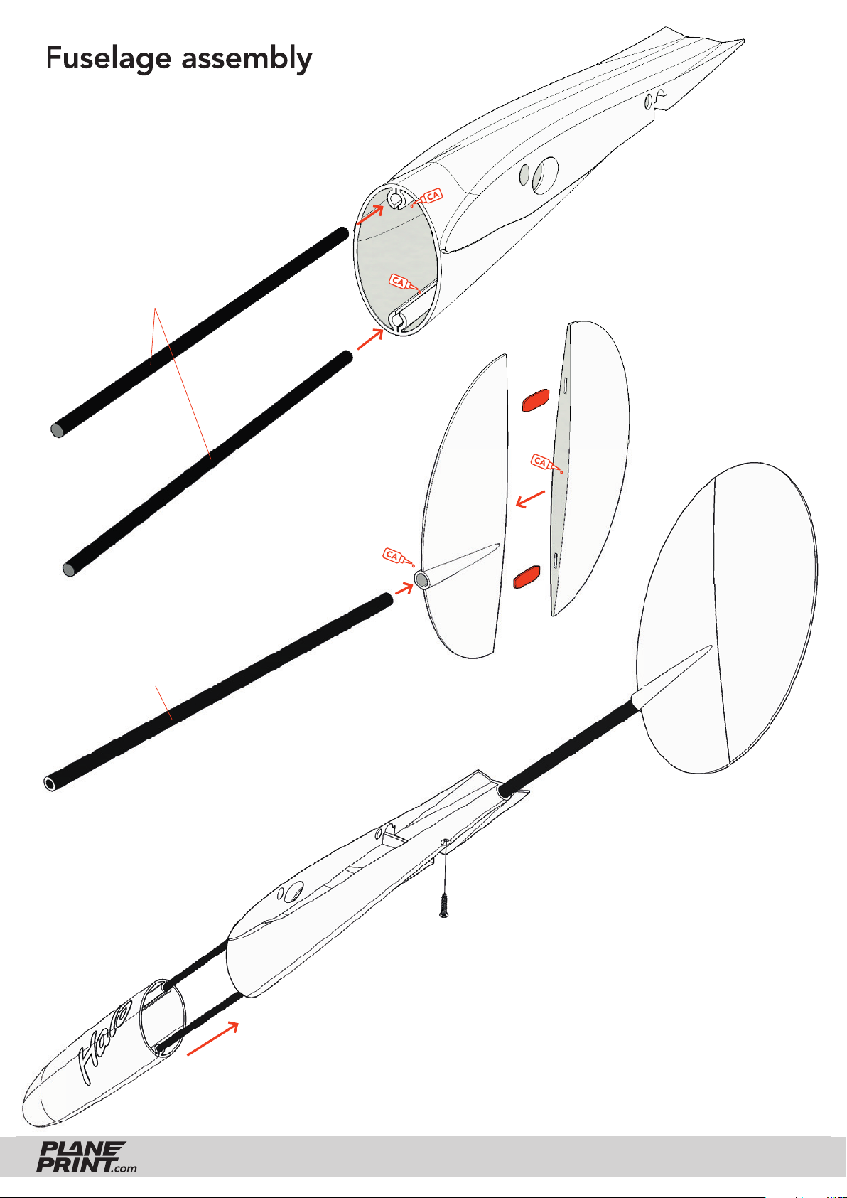
Fuselage assembly
Carbon rods Ø3*115mm
P1_Fuselage_halo.stl
P5_Rudder 2_halo.stl
Carbon tube Ø5*172mm
P5_Rudder 1_halo.stl
P1_Nose_halo.stl
The nose is simply pushed on.
HALO
Tapping screw Ø2mm
Align the rudder exactly vertically and drill a
1.5 mm hole in the carbon tube and screw
the rudder in place.
You can also glue it into the fuselage
without the screw.
PRINTING & ASSEMBLING MANUAL
© PLANEPRINT
12
Page 13
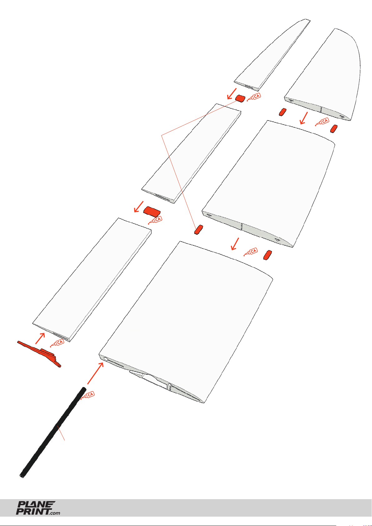
Wing assembly
P5_Aileron L 3_halo.stl
P5_Wing L 3_halo.stl
P1_Parts_halo.stl
P5_Aileron L 2_halo.stl
P5_Wing L 2_halo.stl
P5_Aileron L 1_halo.stl
Carbon tube Ø5*125mm
P5_Wing L 1_halo.stl
HALO
PRINTING & ASSEMBLING MANUAL
© PLANEPRINT
13
Page 14
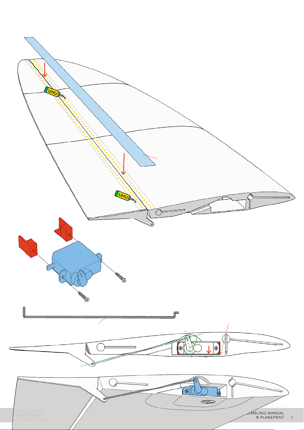
Aileron assembly
The hinges are simply made with adhesive tape. To ensure that the
tape holds well, you should coat the gluing area (LW PLA) with UHU
(or UHU POR) beforehand. Once the adhesive has dried, stick the tape
fi rst to the wing and then to the aileron. Leave a small gap so that the
ailerons can be moved easily.
Tape
P1_Parts_halo.stl
Steel wire Ø0.8*66.4mm
Screw the servo brackets to the servo and position the servo
in the wing as shown here. The servo arm must be at 90°
to the wire at zero position. When the position is correct,
carefully let some CA glue run to the servo brackets without
touching the servo or the wire. Then carefully unscrew the
servo and glue the brackets fi rmly in place.
The servo must not protrude over the wing!
The servo must be as close as possible
to the underside of the wing.
HALO
PRINTING & ASSEMBLING MANUAL
© PLANEPRINT
14
Page 15
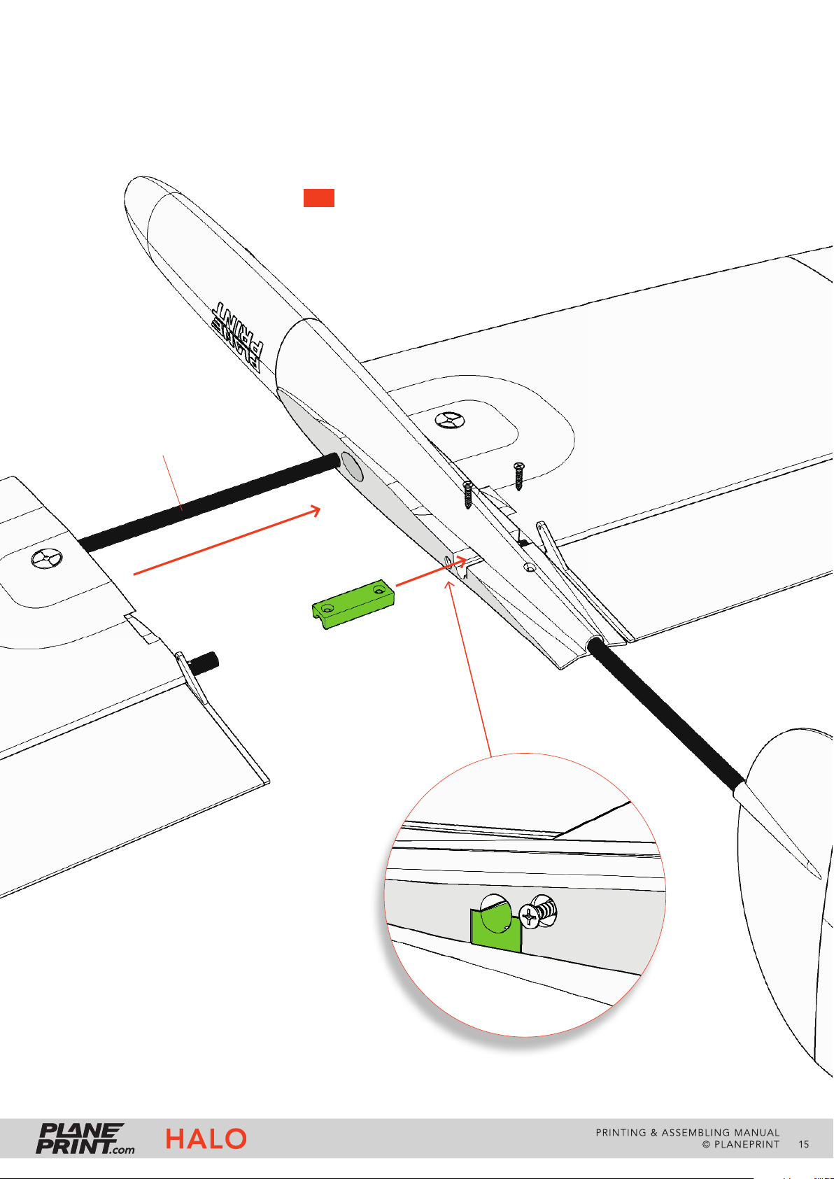
Wing fastening
Carbon tube Ø5*250mm
Insert the TPU mount into the fuselage and the wings too. Then
drill the two 1.5 mm holes in the carbon tubes. Be careful not to
split them! Screw in the sheet metal screws very carefully the fi rst
time so as not to damage the carbon tube.
TIP You can glue a piece of the 3 mm carbon rod into the 5 mm
carbon tube before drilling, this variant is much more durable.
P4_Wing mount_halo.stl
To mount the wings, you can always
leave the TPU mount fi xed on a wing.
HALO
You can store spare
screws here.
PRINTING & ASSEMBLING MANUAL
© PLANEPRINT
15
Page 16
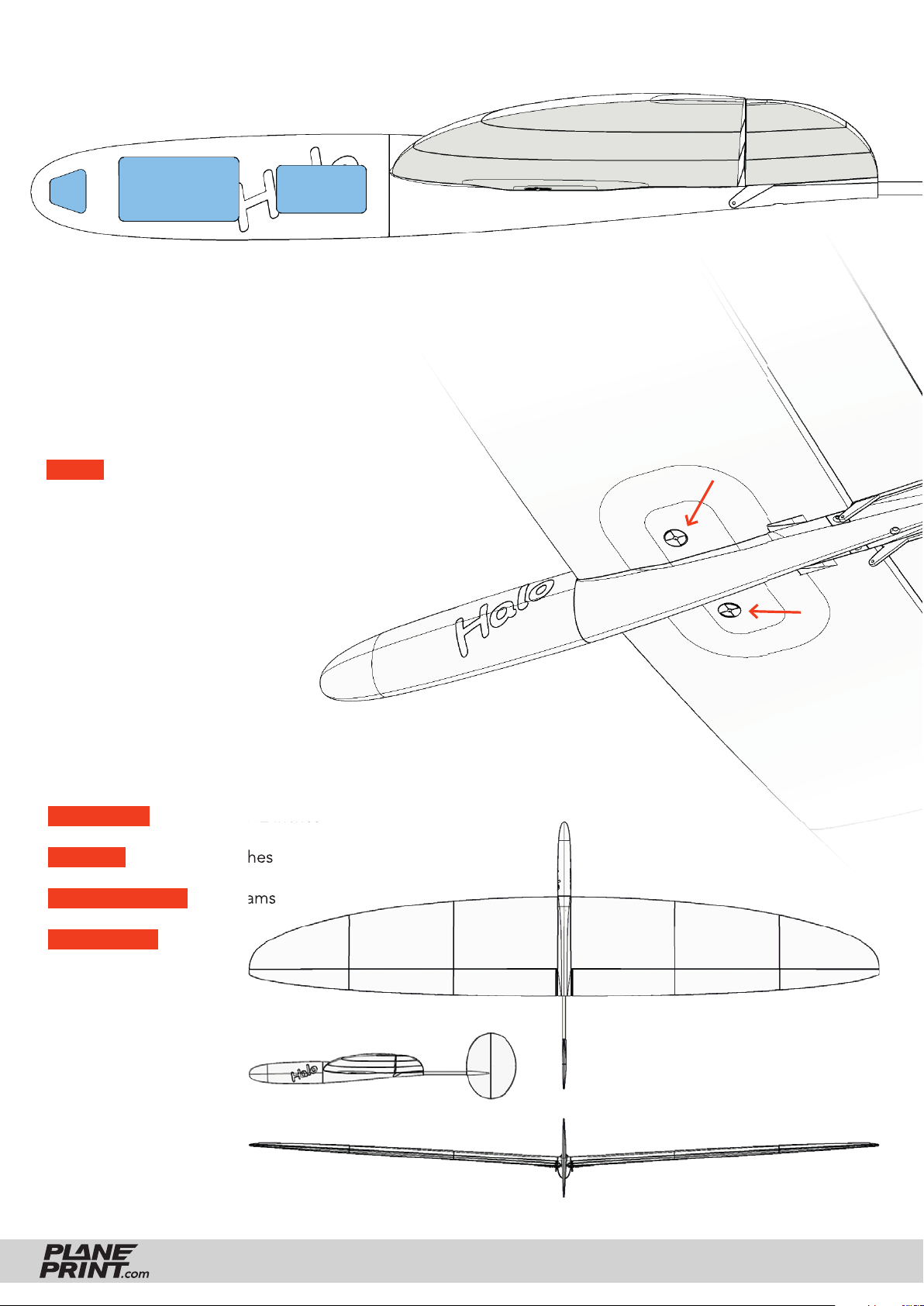
RC components (glider version)
Lead Battery Receiver
Center of Gravity (CG)
The aircraft must balance on these points – see the markings on the wing.
For the fi rst fl ight, the CG should be 50 mm behind the leading edge
and then carefully moved backwards.
NOTE The range of optimum CG is particularly small with a fl ying wing
and you have to fi nd the most comfortable CG for yourself in fl ight. The
further forward it is, the easier the model is to fl y, the further back the
performance is greatest.
Do not forget to check if the wings are exactly in ballance
in the roll axis. If one wing is heavier, correct this
with a small weight on the wingtip.
Technical specifi cations
WINGSPAN 1200 mm/47.2 inches
LENGTH 508 mm/20 inches
FLIGHT WEIGHT 330 grams
WING LOAD 20 g/dm
2
HALO
PRINTING & ASSEMBLING MANUAL
© PLANEPRINT
16
Page 17
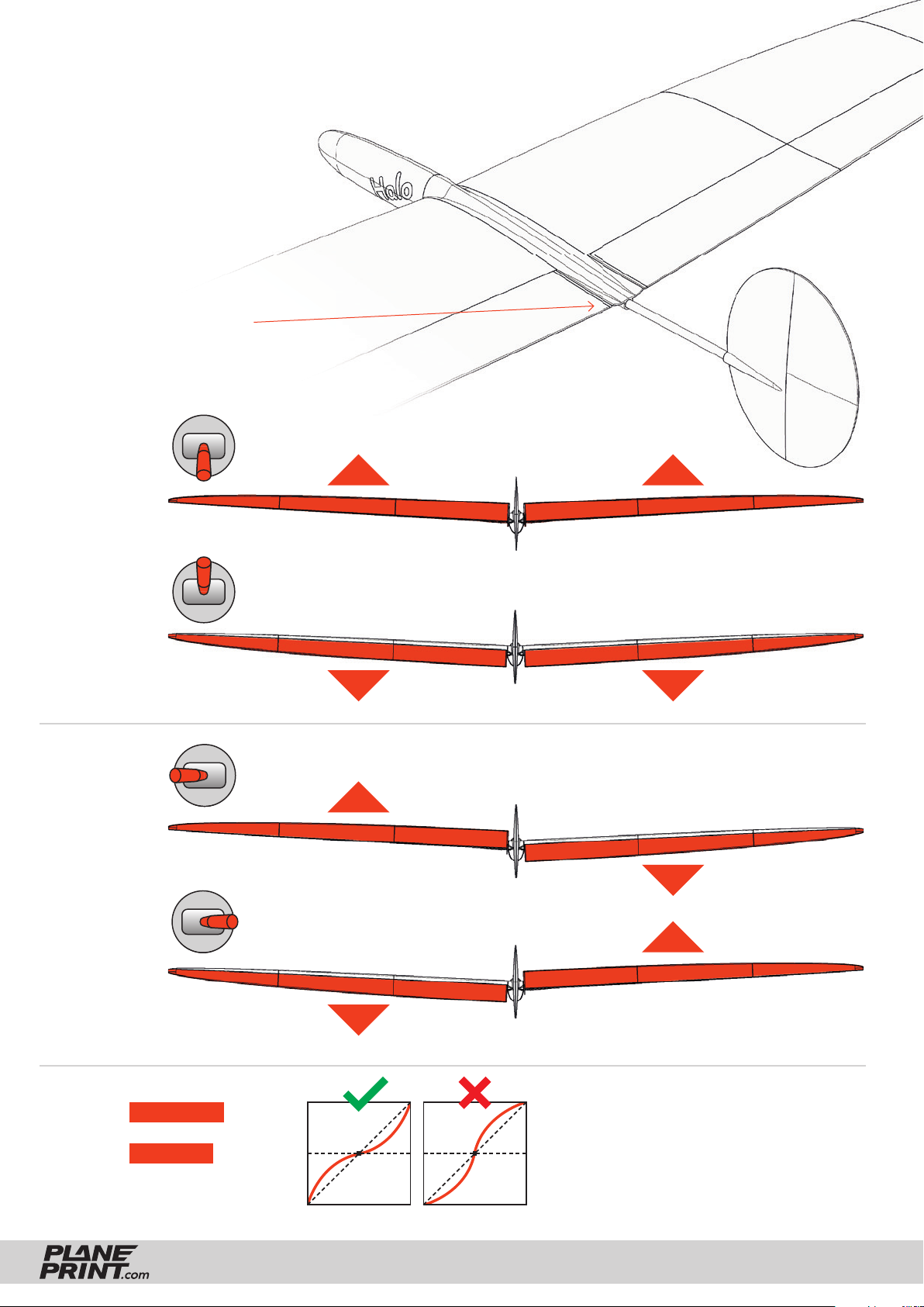
Control Direction Test Look at the aircraft from behind
As a basic setting (zero position),
the ailerons are exactly aligned
with the fuselage position.
ELEVATOR
10 to 12 mm
10 to 12 mm
AILERON
10 to 12 mm
10 to 12 mm
EXPO
ELEVATOR 70 %
AILERON 20 %
HALO
(for some remote
controls a minus
has to be in front
of the number)
PRINTING & ASSEMBLING MANUAL
© PLANEPRINT
17
Page 18

AGE RECOMMENDATION 14+
NOT FOR CHILDREN UNDER 14 YEARS.
THIS IS NOT A TOY!
The STL data (or data processed from it, such as G codes)
must never be passed on to third parties!
The purchase of the STL does not authorize the production
of models for third parties.
By using the download data, an RC model airplane, called
„model“ for short, can be manufactured using a 3D printer.
As a user of this model, only you are responsible for safe
operation that does not endanger you or others, or that
does not damage the model or property of others.
PLANEPRINT.com assumes no responsibility for damage to
persons and property caused by pressure, transport or use
of the product. Filaments, printing supplies, hardware or
consumables that can not be used after faulty 3D printing
will not be replaced by PLANEPRINT.com in any way.
When operating, always keep a safe distance from your
model in all directions to avoid collisions and injuries.
This model is controlled by a radio signal. Radio signals can
be disturbed from outside without being able to influence
it. Interference can lead to a temporary loss of control.
Always operate your model on open terrains, far from cars,
traffic and people.
Keep all chemicals, small parts and electrical components
out of the reach of children.
Avoid water contact with all components that are not specially
designed and protected. Moisture damages the electronics.
Never take an item of the model or accessory in your mouth
as this can lead to severe injuries or even death.
Never operate your model with low batteries in the transmitter or model.
Always keep the model in view and under control.
Use only fully charged batteries.
Always keep the transmitter switched on when the model
is switched on.
Always remove the battery before disassembling the model.
Keep moving parts clean and dry at all times.
Always allow the parts to cool before touching them.
Always remove the battery after use.
Make sure that the Failsafe is properly set before the flight.
Always follow the instructions and warnings for this product
and any optional accessories (servos, receivers, motors,
propellers, chargers, rechargeable batteries, etc.) carefully.
We develop our models to the best of our knowledge and belief.
We accept no liability for consequential damage and injuries
caused by improper use or incorrectly printed parts. Please be
careful when handling motors, batteries and propellers and
only move your model with insurance and in approved places!
Never operate the model with damaged wiring.
Never touch moving parts.
© PLANEPRINT.com, A-6021 Innsbruck, Conradstraße 6, [email protected]
© Design STL files by René Marschall • Layout: marschall designlab, marschall.cc
 Loading...