

Page 1
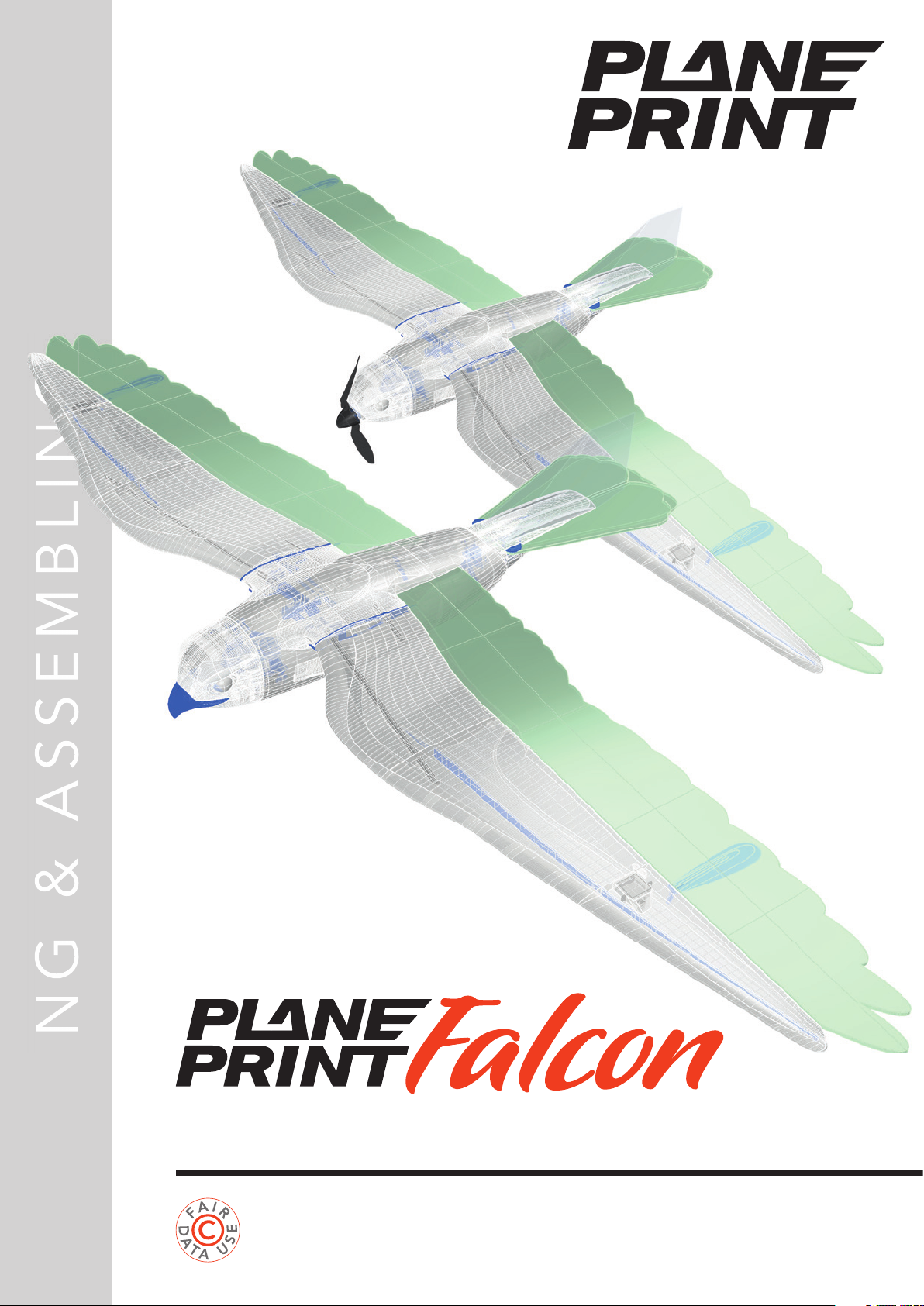
Realistic Bird model – motor and glider version
www.planeprint.com
the ONLY place where you can get
original Planeprint STL fi les legally!
PRINTING & ASSEMBLING MANUAL
Page 2
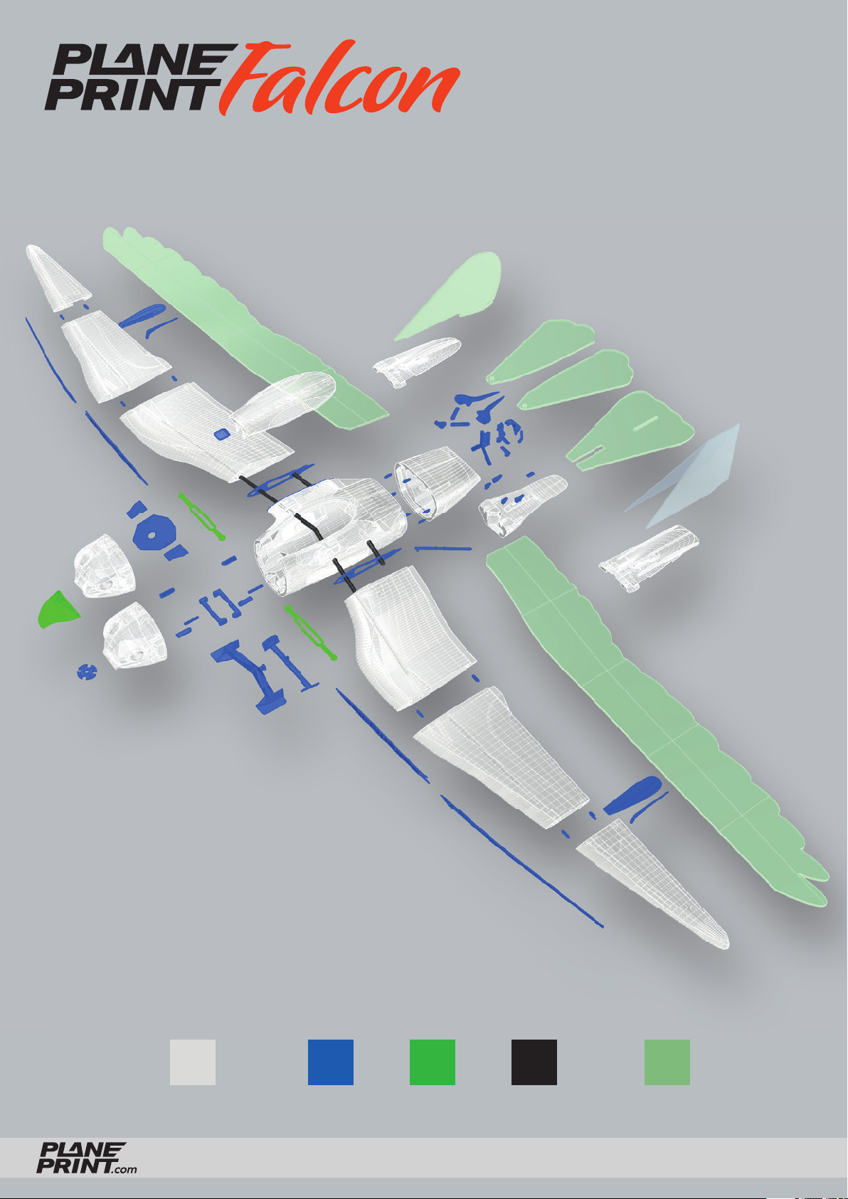
PLA TPULW-PLA Foam boardCarbon
FALCON
PRINTING & ASSEMBLING MANUAL
© PLANEPRINT
2
Page 3
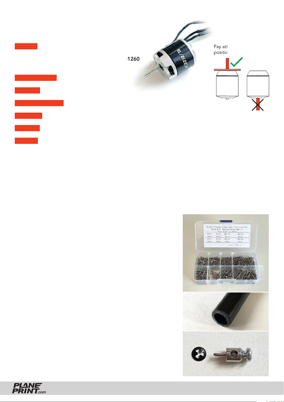
RC Components
MOTOR Motors up to Ø 35 mm, for example:
• XPower XC2212/18
• Torcster Brushless Gold A2822/17-1260
or comparable motors
FOLDING PROP 6x4-7x4.5
SPINNER Ø 30mm
BEC-CONTROLLER min. 15 A (must fi t the engine!)
RECEIVER 4 Channel (Glider), 5 Channel (Motor version)
BATTERY 3S Lipo, about 600-1000 MaH (perfect weight 70-80 grams)
SERVOS Rudder and Elevator: 2 Micro Servos for example:
• SERVO HITEC HS-5055 MG DIGITAL
(or similar in the same size, It should have a metal gear)
Ailerons: 2 Nano Servos for example:
• CHASERVO D S 06 (fi ts perfect) • Hitec HS 40 Eco Servo 4,8g
• Diamond D47 • PLANET-HOBBY ECO PLUS
• Stemedu Micro 3.7g Servo GH-S37D • PICCO 8 DIGITAL SERVO
Pay attention to the
position of the motor shaft
Required accessoires – basic equipment
Links to recommended accessories can be found on
www.planeprint.com/falcon (scroll down)
• LW-PLA (cannot be replaced by PLA or pre-foamed LW), ~250 grams
• PLA or Tough PLA, ~70 grams
• TPU A95, ~20 grams
• CA super glue (liquid and medium)
• CA activator
• some tapping screws Ø2mm
• UHU POR glue (or another glue suitable for Depron and Foam)
• Foam board 3 mm uncoated!* (or Foam like Depron, Styropor or EPP,
you can see how much you need on the next pages
– Such boards are also available separately in model shops)
• Carbon tube Ø6*1000mm, 1 piece (2x310mm, 2x70mm)
• Steel wire Ø1*1000mm, 1 piece (2x300mm, 2x50mm)
• Rod connection small, 2 pieces
• Neodym-Super-Magnet 5x5x5mm, 2 pieces
• Overhead transparency, 1 piece (200x200 mm)
(This fi lm must not be too heavy! A thickness of 0.2 mm is ideal)
• Fabric tape or fabric
• Adhesive tape
• Self adhesive velcro tape
Tapping screws Ø2mm
Carbon tube
Rod connection hole 1 mm
* These Foam parts cannot be printed for weight reasons,
LW PLA is much heavier than foam.
FALCON
PRINTING & ASSEMBLING MANUAL
© PLANEPRINT
3
Page 4
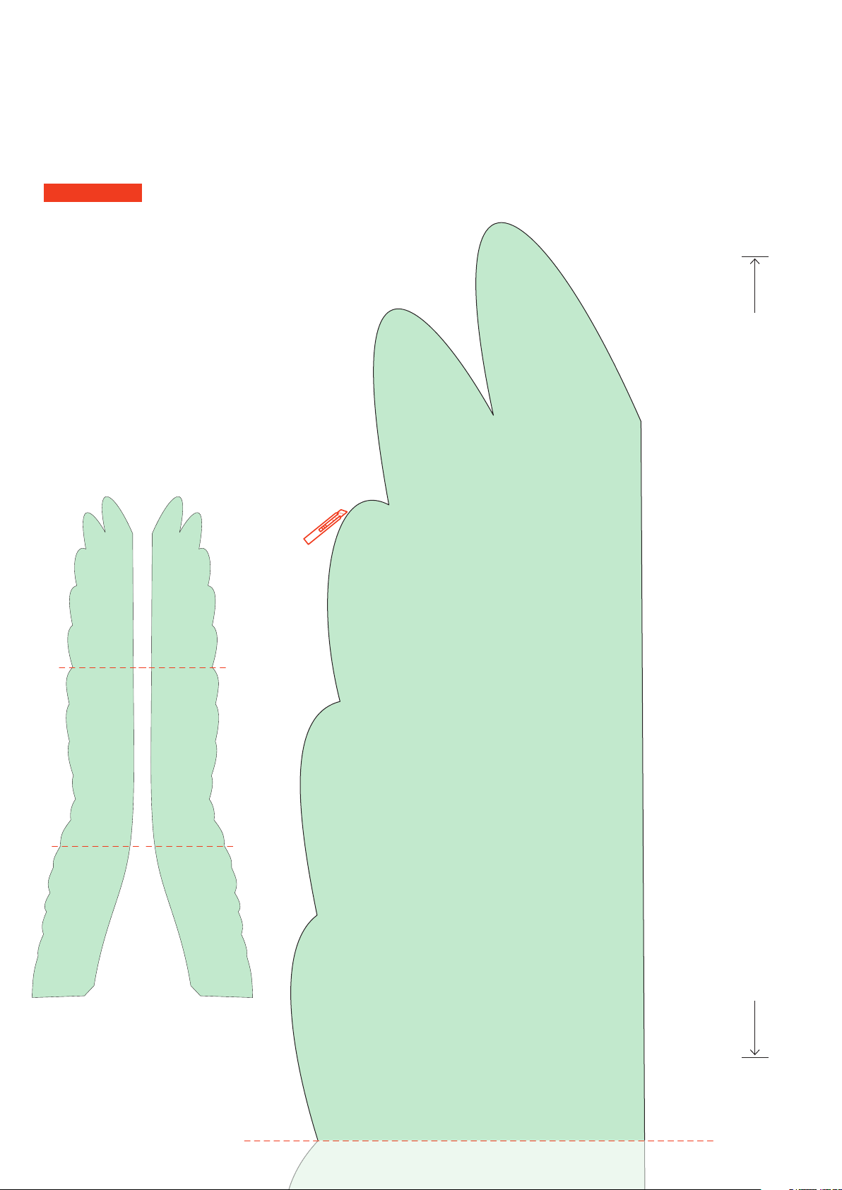
Cutting template for the Foam parts
Print out these pages on A4 paper and cut out the templates. For the Aileron, cut them
out along the red dotted line and glue the parts together exactly. Attach them to the foam
board and cut the foam parts with a sharp knife.
IMPORTANT The print must be set to 100% page size, so that the size fi ts exactly!
Glue this 3 templates together fi rst
Aileron/Wing
(two pieces mirror-inverted)
Here you can check whether the print is the exact size. This length must measure exactly 200 mm
Page 5
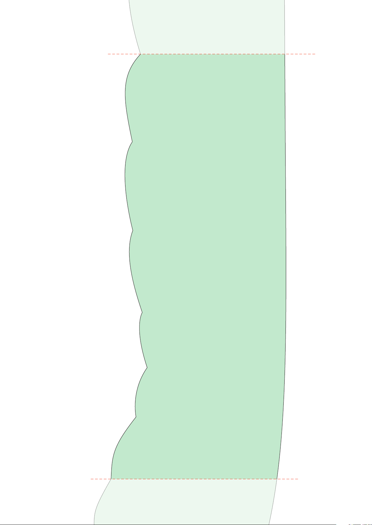
Aileron/Wing
(two pieces mirror-inverted)
Page 6
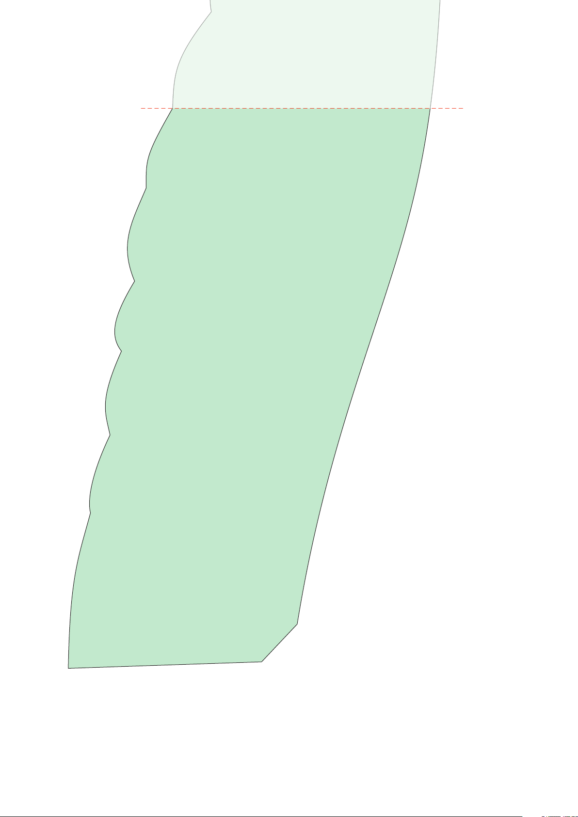
Aileron/Wing
(two pieces mirror-inverted)
Page 7
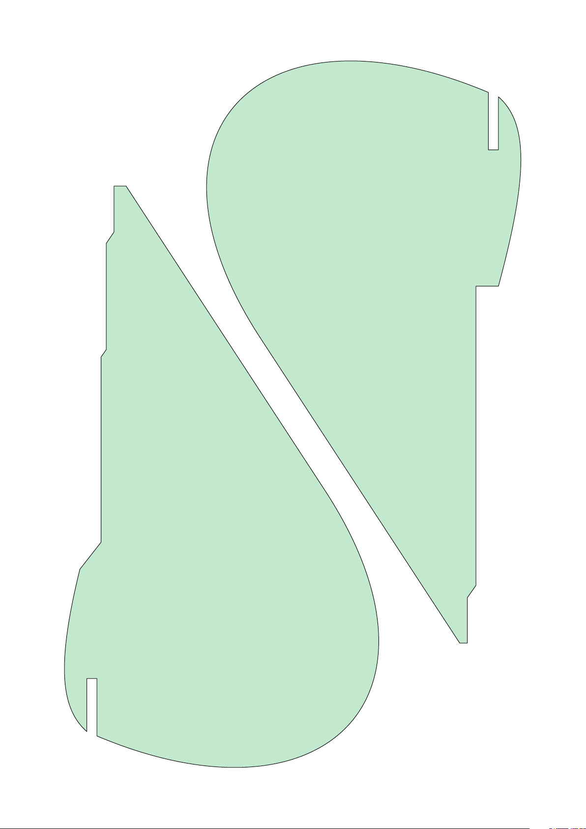
There are different versions here!
You can decide which one you want to build
in the manual further down.
Rudder Foam rigid version
Rudder Foam spread version
Page 8
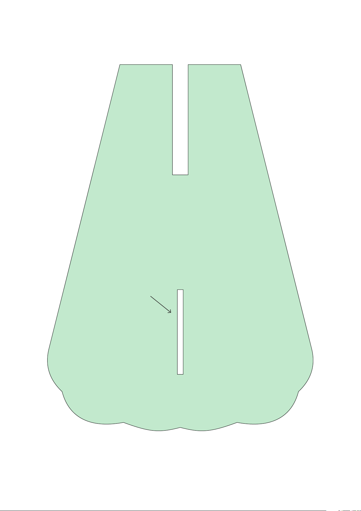
Elevator Foam rigid version
This opening is
ONLY required if the
rudder is built in the
foam version.
Page 9
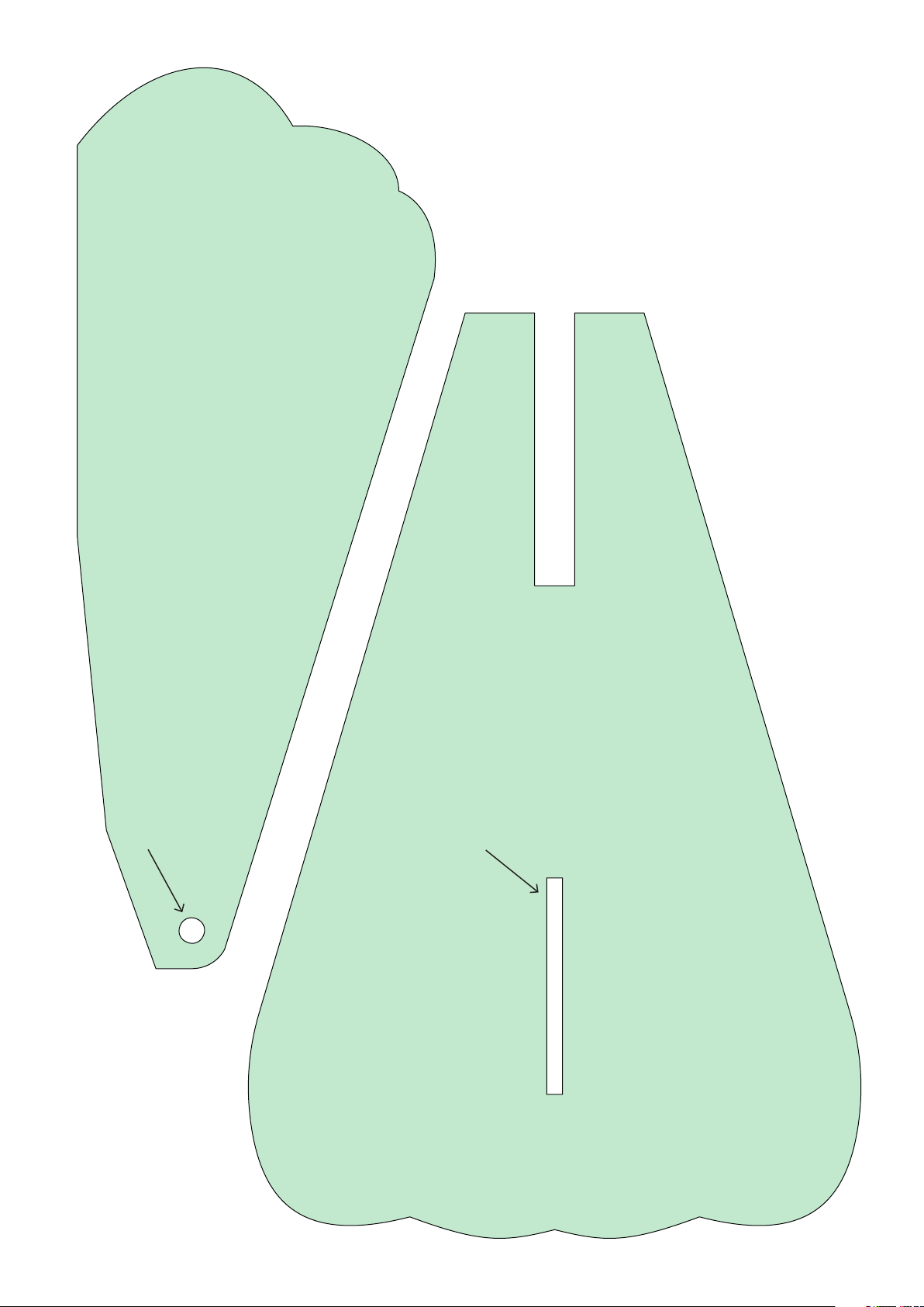
Elevator spread version
(two pieces mirror-inverted)
There must be
an opening here
Elevator spread version
This opening is
ONLY required if the
rudder is built in the
foam version.
Page 10
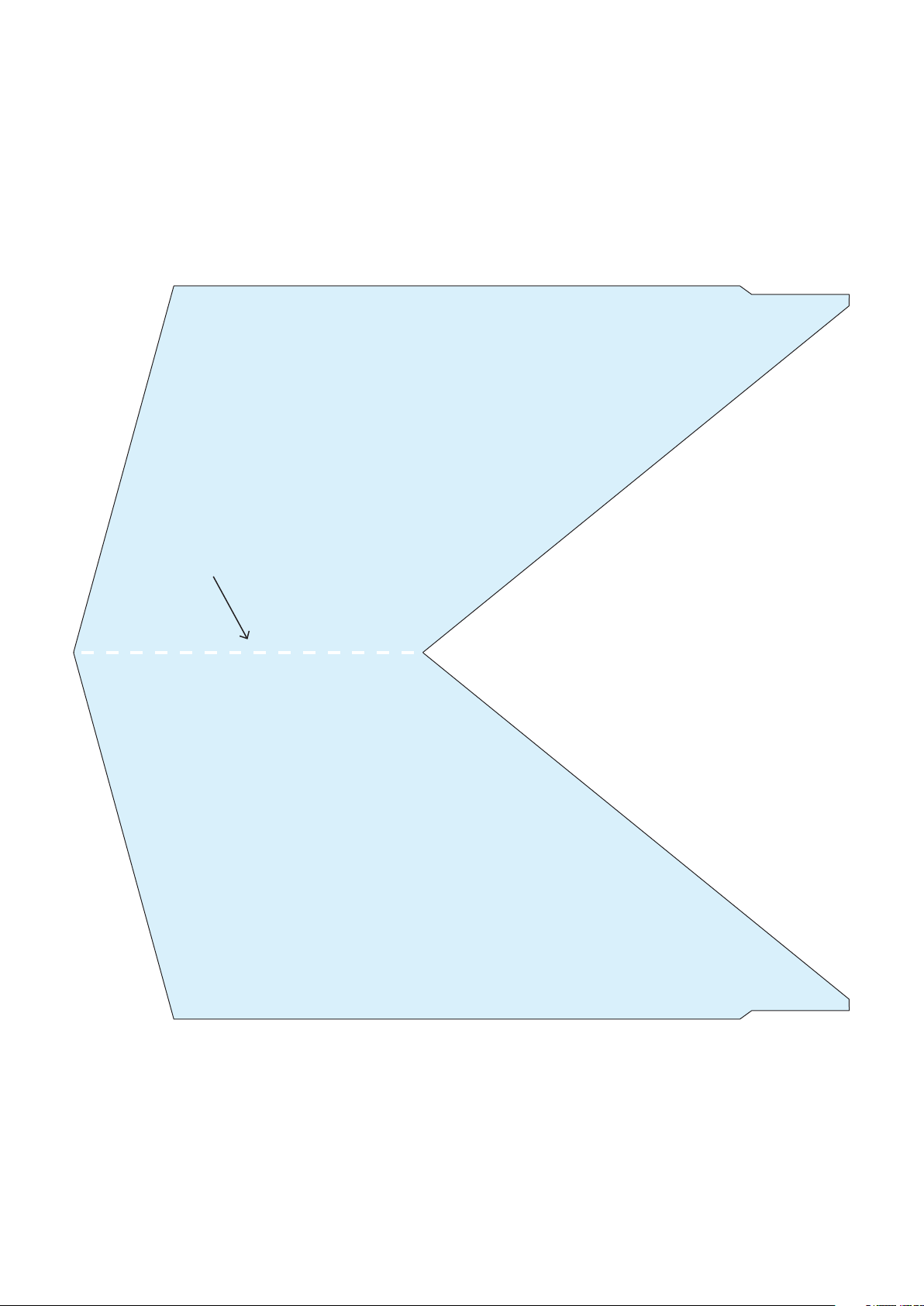
Fold here
Rudder
Overhead transparency version
Page 11

The development of a complex, airworthy RC flight model to express on any standard 3D printer is a very extensive process. Therefore, we appeal to your fairness
not to forward the STL data you have acquired to third parties.
Thank you for your understanding and have fun with your PLANEPRINT MODEL!
Printing the parts – Printing profiles
This manual is constantly being improved and supplemented, we recommend
downloading the latest version from our website before building.
To print all PLANEPRINT models you need to set some basic profiles in Cura
(If you use another slicer, please set the same parameters).
You can find the description at www.planeprint.com/print
For this model you need the following profiles:
FALCON
PRINTING & ASSEMBLING MANUAL
© PLANEPRINT
11
Page 12
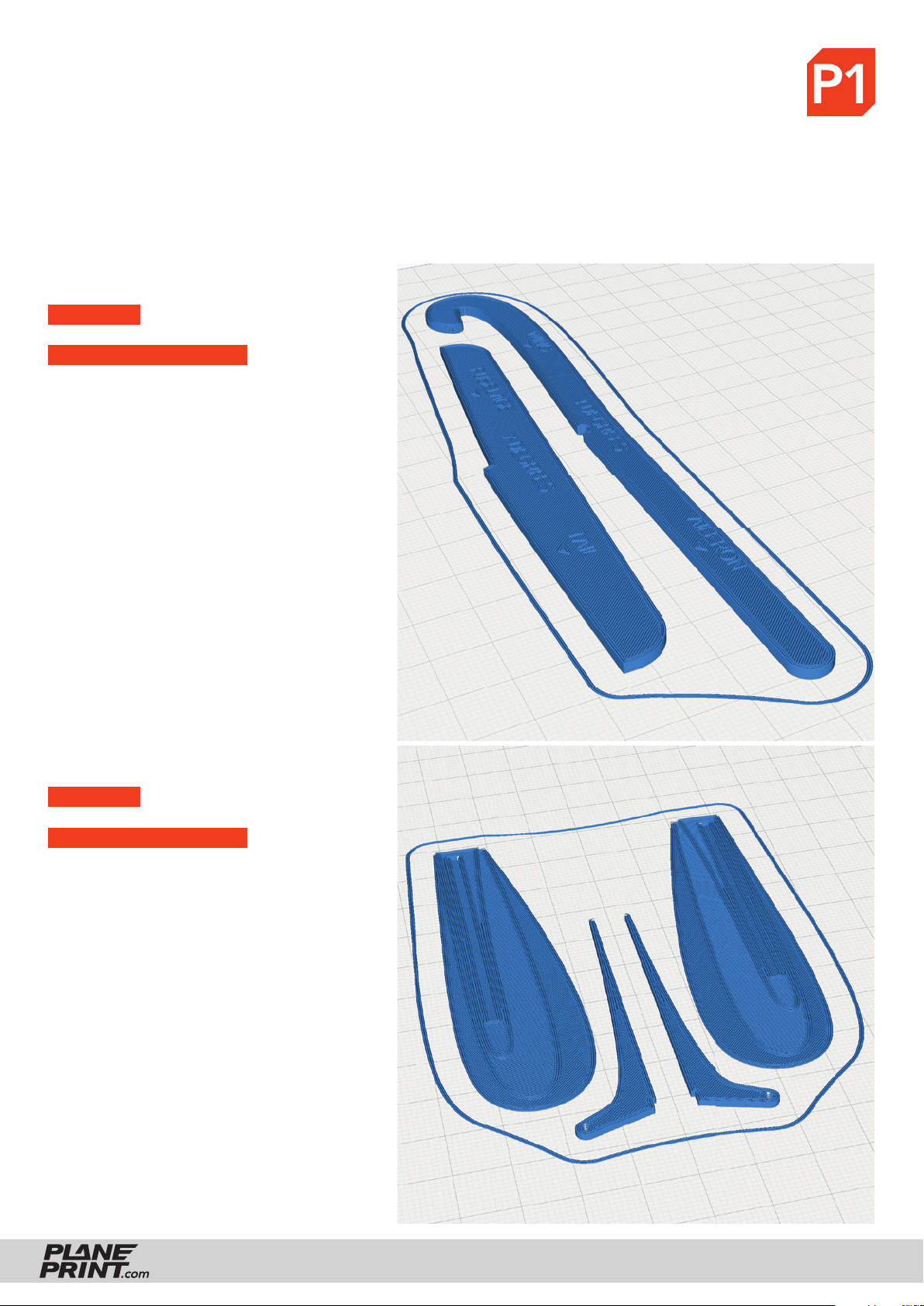
PROFILE P1_Fullbody Tough PLA or PLA
The information about the basic settings you can fi nd on our website at PRINT.
Please note the additional settings for the individual parts!
P1_Setting gauges-fn.stl
MATERIAL PLA, Weight: ~ 7 g
ADDITIONAL SETTINGS
Wall Line Count/Perimeters: 20
P1_AIL horns-fn.stl
MATERIAL PLA, Weight: ~ 3 g
ADDITIONAL SETTINGS
None required
FALCON
PRINTING & ASSEMBLING MANUAL
© PLANEPRINT
12
Page 13
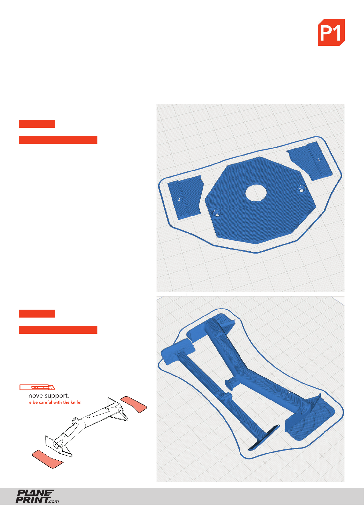
PROFILE P1_Fullbody Tough PLA or PLA
The information about the basic settings you can fi nd on our website at PRINT.
Please note the additional settings for the individual parts!
P1_battery mount-fn.stl
MATERIAL PLA, Weight: ~ 6 g
ADDITIONAL SETTINGS
None required
P1_Center parts-fn.stl
MATERIAL PLA, Weight: ~ 17 g
ADDITIONAL SETTINGS
Wall Line Count/Perimeters: 3
Remove support.
Please be careful with the knife!
FALCON
PRINTING & ASSEMBLING MANUAL
© PLANEPRINT
13
Page 14
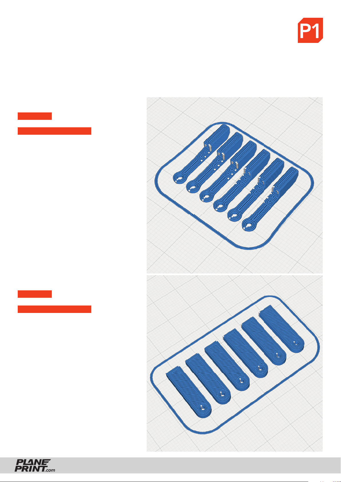
PROFILE P1_Fullbody Tough PLA or PLA
The information about the basic settings you can fi nd on our website at PRINT.
Please note the additional settings for the individual parts!
P1_Clips-fn.stl
MATERIAL PLA, Weight: ~ 1 g
ADDITIONAL SETTINGS
None required
P1_Head mount-fn.stl
MATERIAL PLA, Weight: ~ 2 g
ADDITIONAL SETTINGS
None required
FALCON
PRINTING & ASSEMBLING MANUAL
© PLANEPRINT
14
Page 15
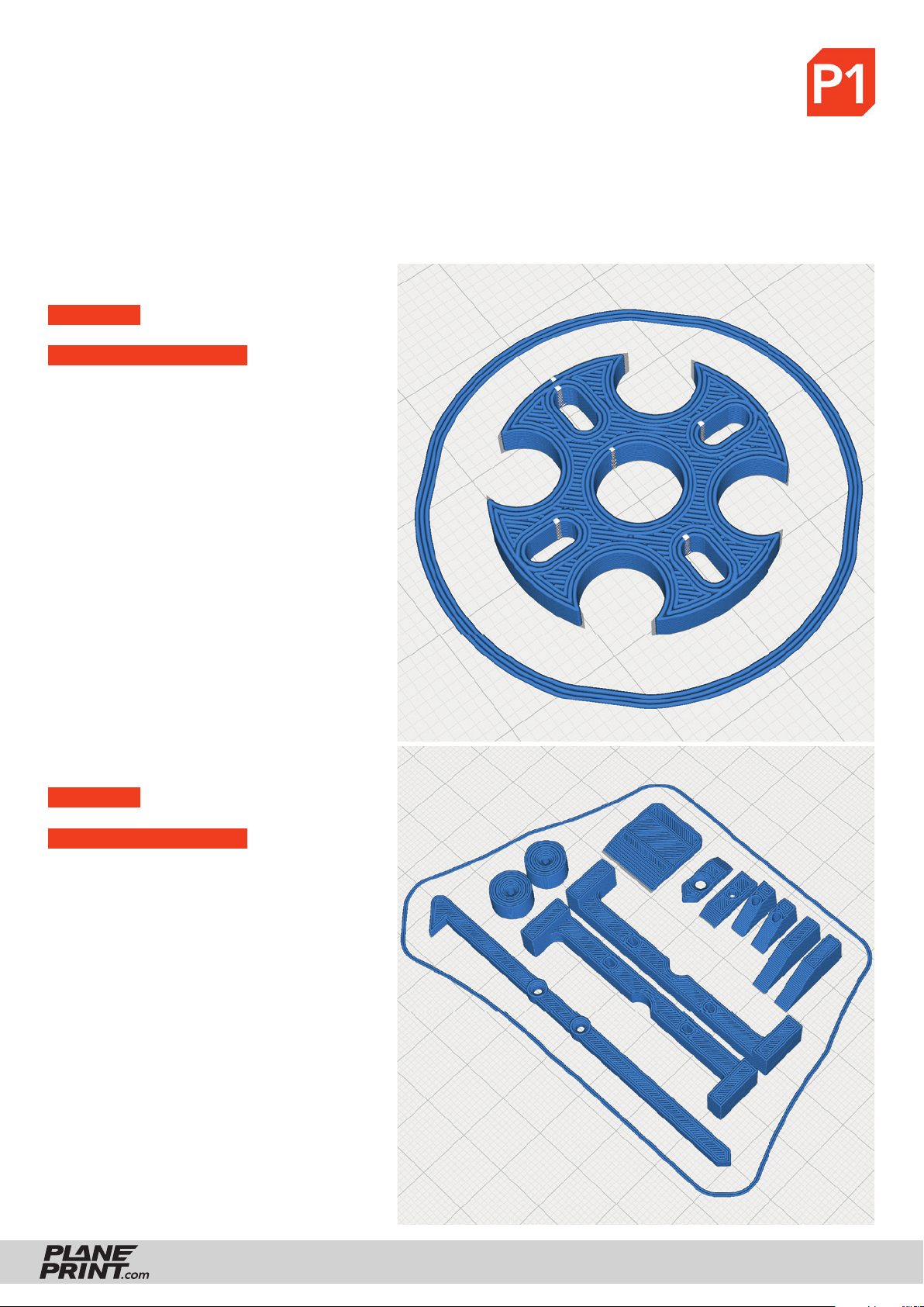
PROFILE P1_Fullbody Tough PLA or PLA
The information about the basic settings you can fi nd on our website at PRINT.
Please note the additional settings for the individual parts!
P1_Motor mount 16-19-fn.stl
MATERIAL PLA, Weight: ~ 1 g
ADDITIONAL SETTINGS
None required
P1_Parts-fn.stl
MATERIAL PLA, Weight: ~ 6 g
ADDITIONAL SETTINGS
None required
FALCON
PRINTING & ASSEMBLING MANUAL
© PLANEPRINT
15
Page 16
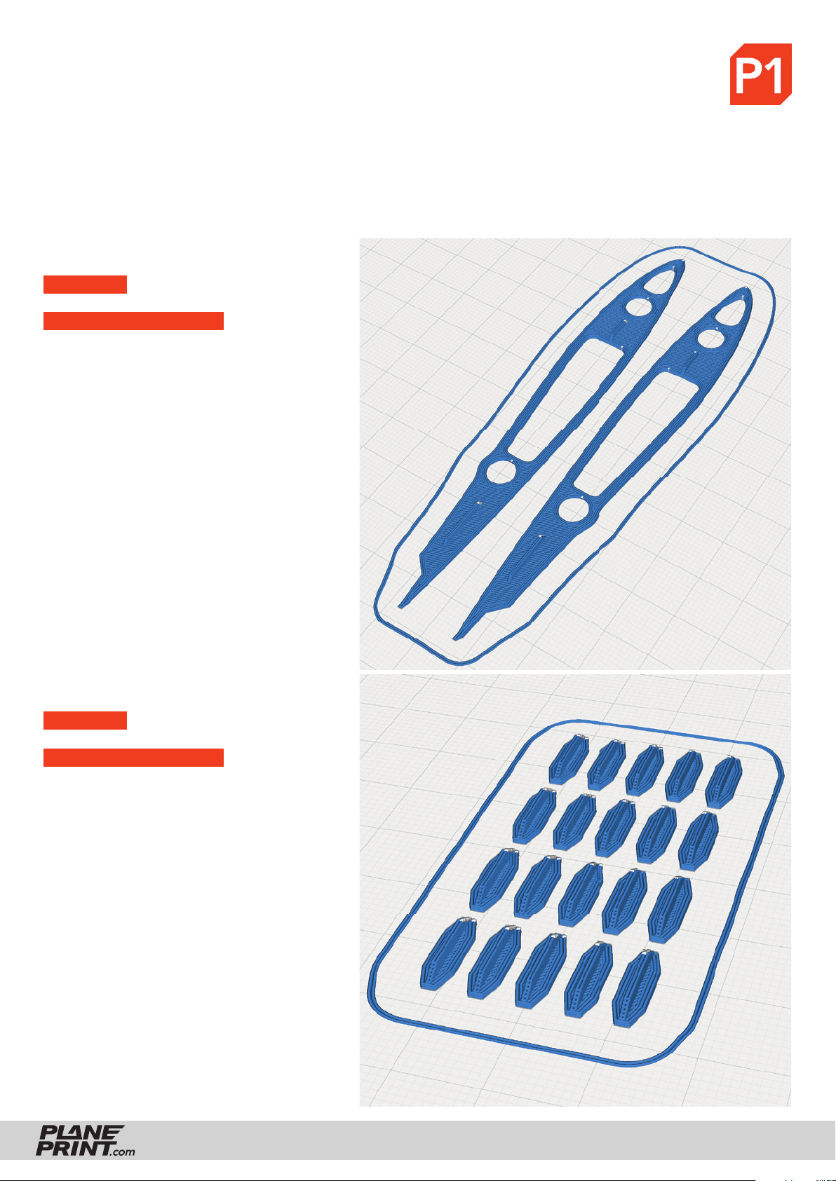
PROFILE P1_Fullbody Tough PLA or PLA
The information about the basic settings you can fi nd on our website at PRINT.
Please note the additional settings for the individual parts!
P1_Protectors-fn.stl
MATERIAL PLA, Weight: ~ 2 g
ADDITIONAL SETTINGS
None required
P1_T-connects-fn.stl
MATERIAL PLA, Weight: ~ 1 g
ADDITIONAL SETTINGS
None required
FALCON
PRINTING & ASSEMBLING MANUAL
© PLANEPRINT
16
Page 17
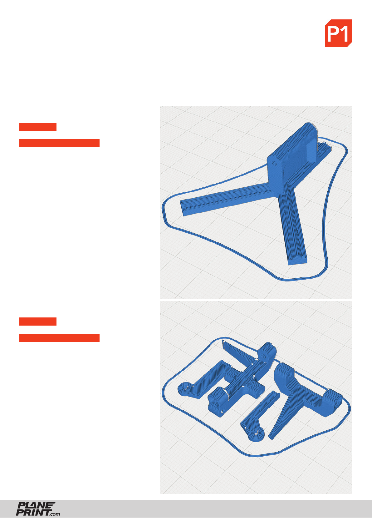
PROFILE P1_Fullbody Tough PLA or PLA
The information about the basic settings you can fi nd on our website at PRINT.
Please note the additional settings for the individual parts!
P1_Tail joint 1-fn.stl
MATERIAL PLA, Weight: ~ 2 g
ADDITIONAL SETTINGS
None required
P1_Tail joint 2-fn.stl
MATERIAL PLA, Weight: ~ 3 g
ADDITIONAL SETTINGS
None required
FALCON
PRINTING & ASSEMBLING MANUAL
© PLANEPRINT
17
Page 18
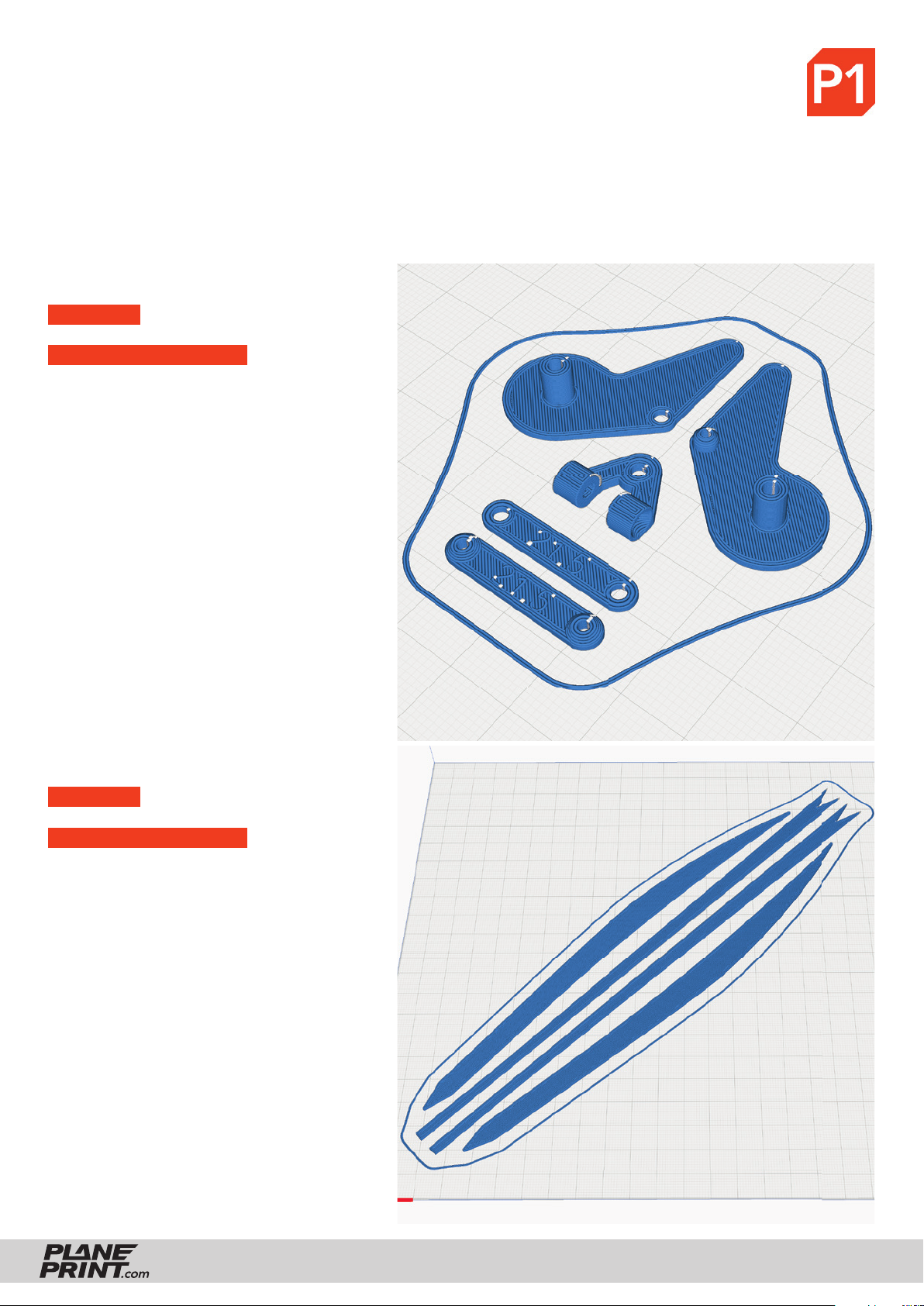
PROFILE P1_Fullbody Tough PLA or PLA
The information about the basic settings you can fi nd on our website at PRINT.
Please note the additional settings for the individual parts!
P1_Tail joint 3-fn.stl
MATERIAL PLA, Weight: ~ 2 g
ADDITIONAL SETTINGS
None required
P1_Wing Spar-fn.stl
MATERIAL PLA, Weight: ~ 10 g
ADDITIONAL SETTINGS
None required
FALCON
PRINTING & ASSEMBLING MANUAL
© PLANEPRINT
18
Page 19
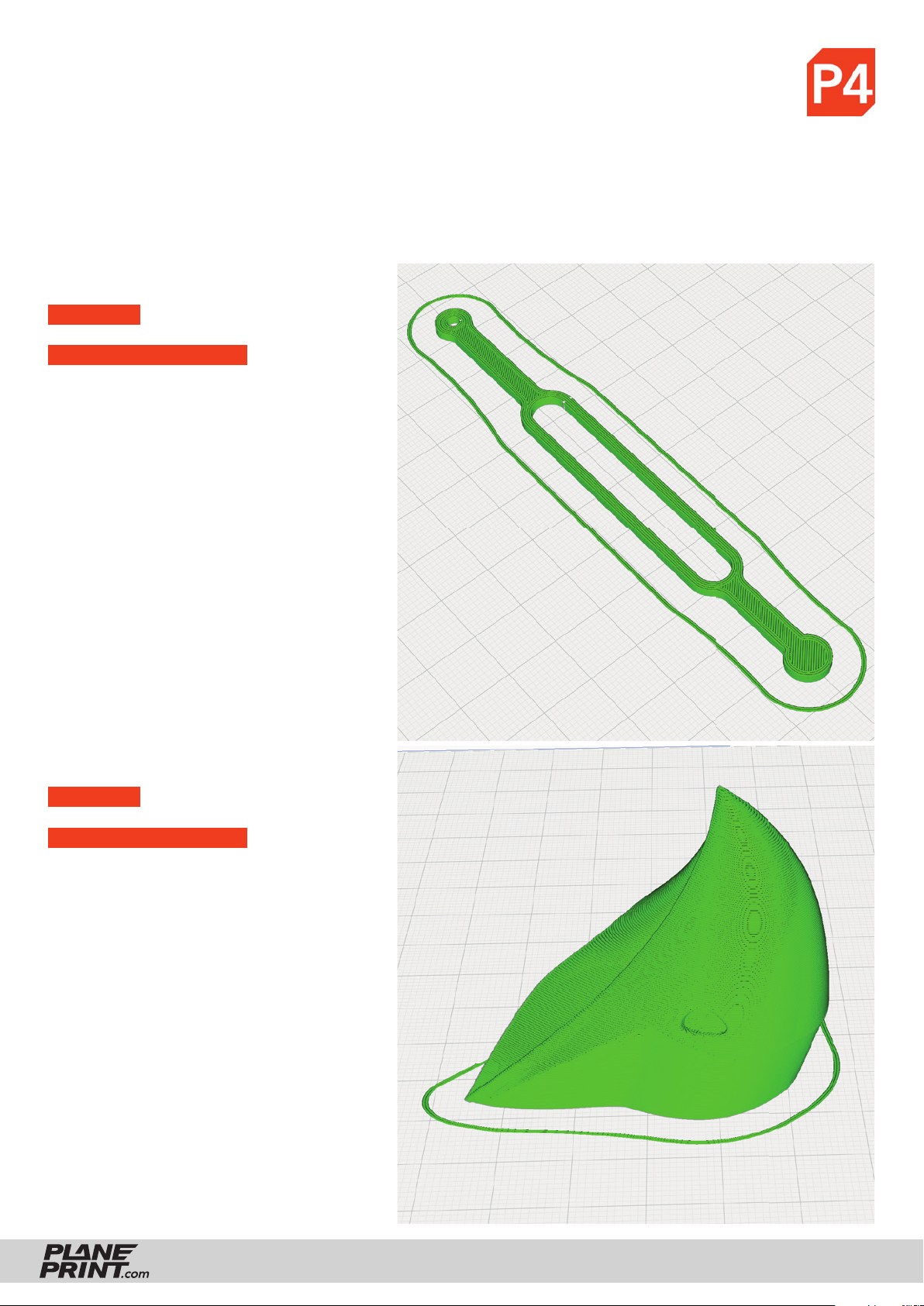
PROFILE P4_Flex TPU A95
The information about the basic settings you can fi nd on our website at PRINT.
Please note the additional settings for the individual parts!
P4_Tension belt-fn.stl
MATERIAL TPU, Weight: ~ 1 g
ADDITIONAL SETTINGS
• Infi ll Density: 100 %
• print twice
P4_Beak-fn.stl
MATERIAL TPU, Weight: ~ 14 g
ADDITIONAL SETTINGS
• Infi ll Density: 100 %
You can also print this part with PLA.
TPU has the advantage that it is softer
and the tip cannot break off.
FALCON
PRINTING & ASSEMBLING MANUAL
© PLANEPRINT
19
Page 20
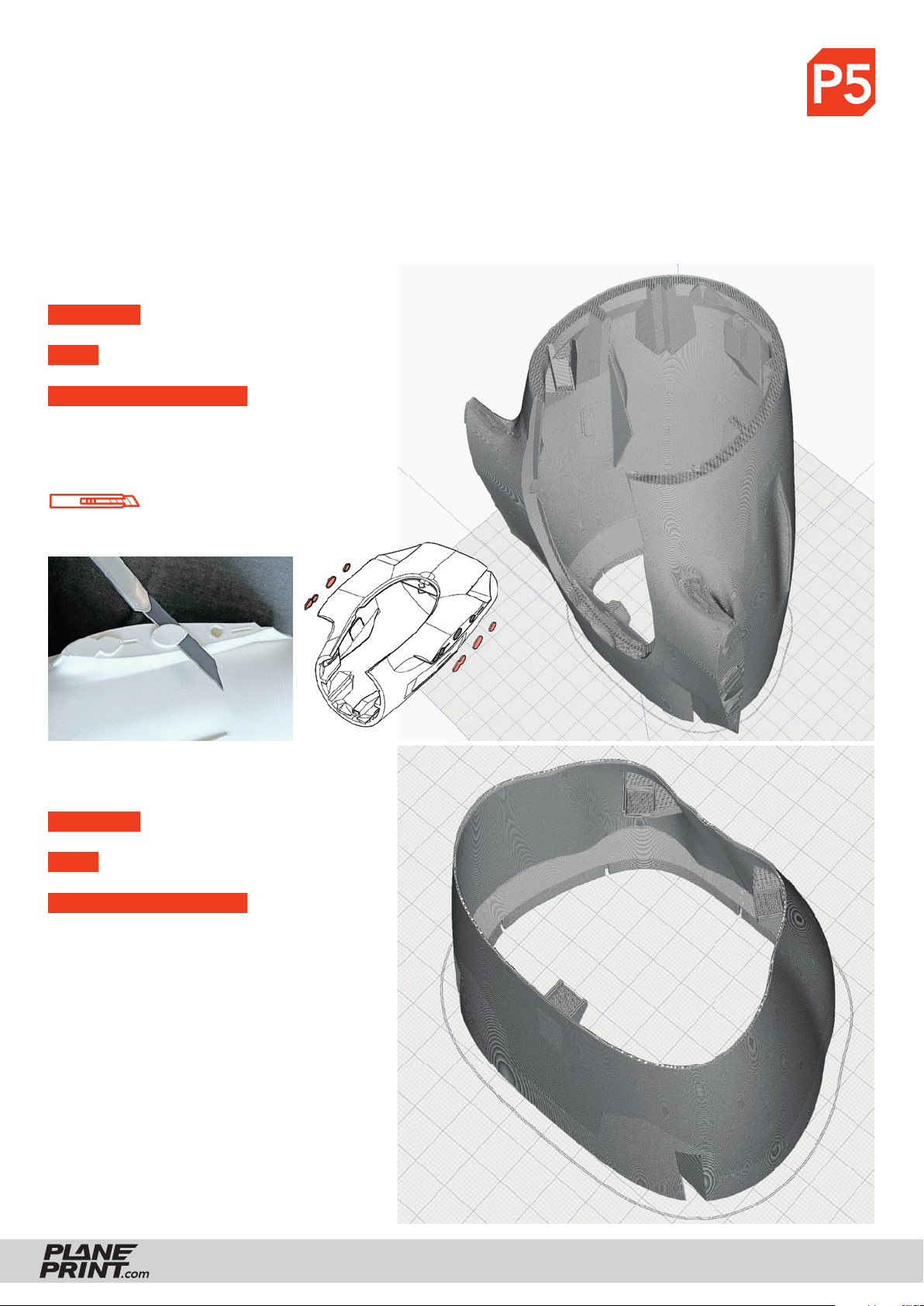
PROFILE P5_Gyroid Light-Weight LW-PLA!
The information about the basic settings you can fi nd on our website at PRINT.
Please note the additional settings for the individual parts!
It is essential to print these parts with foaming LW-PLA (not pre-foamed)!
Basic settings for LW-PLA: Please follow the instructions in our WINGTEST AND CALIBRATION TOOL on our
website for correct adjustment! For optimum quality, there should only ever be one part on the build plate!
P5_Body 1-fn.rstl
MATERIAL LW PLA, Weight: ~ 49 g
TIME ~ 9 hours
ADDITIONAL SETTINGS
• Infi ll Density/Fill Density: 3 %
Remove support.
Please be careful with the knife!
P5_Body 2-fn.stl
MATERIAL LW PLA, Weight: ~ 17 g
TIME ~ 2 hours 40 minutes
ADDITIONAL SETTINGS
• Infi ll Density/Fill Density: 3 %
Remove the stringing threads
FALCON
PRINTING & ASSEMBLING MANUAL
© PLANEPRINT
20
Page 21
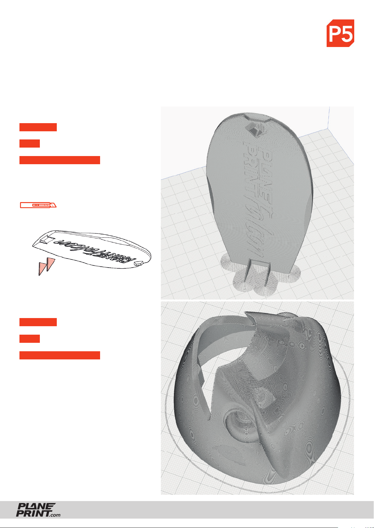
PROFILE P5_Gyroid Light-Weight LW-PLA!
The information about the basic settings you can fi nd on our website at PRINT.
Please note the additional settings for the individual parts!
It is essential to print these parts with foaming LW-PLA (not pre-foamed)!
Basic settings for LW-PLA: Please follow the instructions in our WINGTEST AND CALIBRATION TOOL on our
website for correct adjustment! For optimum quality, there should only ever be one part on the build plate!
P5_Cover-fn.stl
MATERIAL LW PLA, Weight: ~ 7 g
TIME ~ 1 hour 15 minutes
ADDITIONAL SETTINGS
• Infi ll Density/Fill Density: 3 %
• Brim
Remove support.
Please be careful with the knife!
P5_Head glider-fn.stl
MATERIAL LW PLA, Weight: ~ 13 g
TIME ~ 2 hours 30 minutes
ADDITIONAL SETTINGS
• Infi ll Density/Fill Density: 8 %
Remove the stringing threads
FALCON
PRINTING & ASSEMBLING MANUAL
© PLANEPRINT
21
Page 22
PROFILE P5_Gyroid Light-Weight LW-PLA!
The information about the basic settings you can fi nd on our website at PRINT.
Please note the additional settings for the individual parts!
It is essential to print these parts with foaming LW-PLA (not pre-foamed)!
Basic settings for LW-PLA: Please follow the instructions in our WINGTEST AND CALIBRATION TOOL on our
website for correct adjustment! For optimum quality, there should only ever be one part on the build plate!
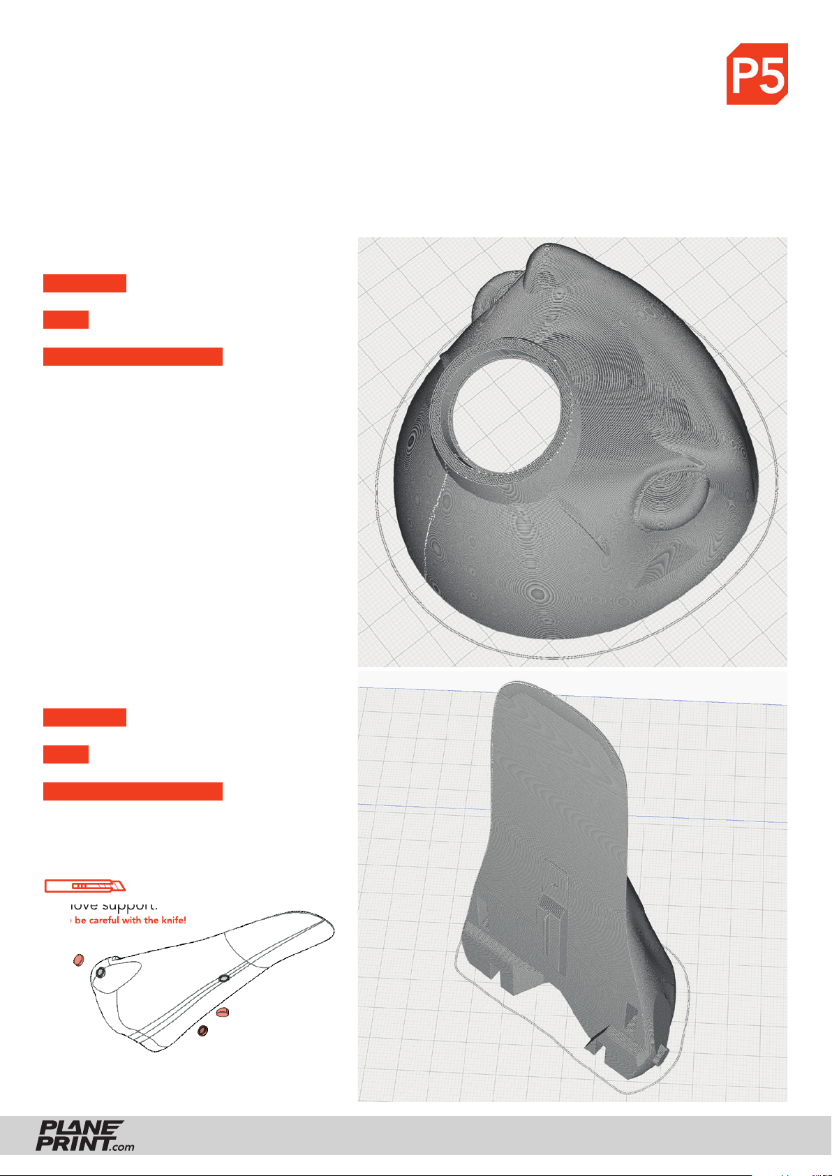
P5_Head motor-fn.rstl
MATERIAL LW PLA, Weight: ~ 14 g
TIME ~ 2 hours 30 minutes
ADDITIONAL SETTINGS
• Infi ll Density/Fill Density: 8 %
P5_Tail base-fn.stl
MATERIAL LW PLA, Weight: ~ 9 g
TIME ~ 1 hour 30 minutes
ADDITIONAL SETTINGS
• Infi ll Density/Fill Density: 3 %
Remove support.
Please be careful with the knife!
FALCON
PRINTING & ASSEMBLING MANUAL
© PLANEPRINT
22
Page 23
PROFILE P5_Gyroid Light-Weight LW-PLA!
The information about the basic settings you can fi nd on our website at PRINT.
Please note the additional settings for the individual parts!
It is essential to print these parts with foaming LW-PLA (not pre-foamed)!
Basic settings for LW-PLA: Please follow the instructions in our WINGTEST AND CALIBRATION TOOL on our
website for correct adjustment! For optimum quality, there should only ever be one part on the build plate!
There are four versions here!
You can decide which one you want to build
in the manual further down.
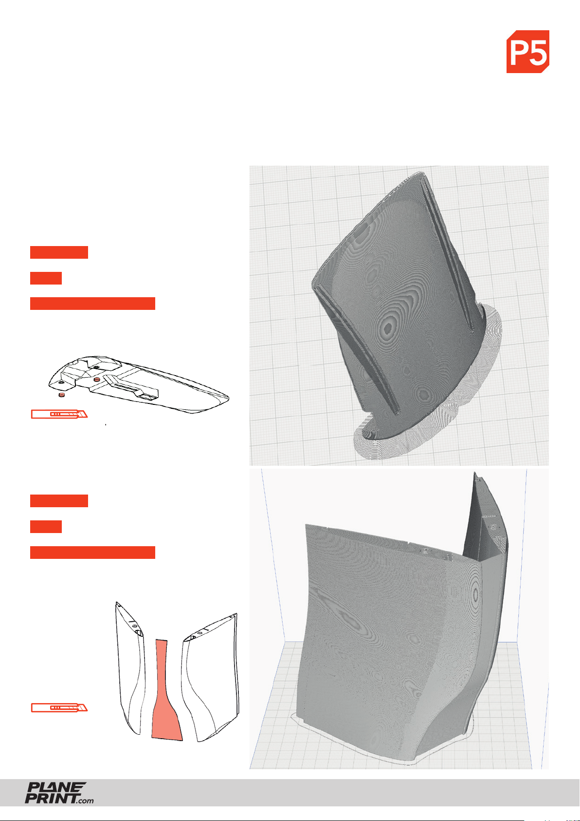
P5_Tail XXX-fn.stl
MATERIAL LW PLA, Weight: ~ 7 to 8 g
TIME ~ 1 hour 20 minutes
ADDITIONAL SETTINGS
• Infi ll Density/Fill Density: 3 %
• Brim
Remove support.
Please be careful with the knife!
P5_Wings 1-fn.stl
MATERIAL LW PLA, Weight: ~ 59 g
TIME ~ 10 hours
ADDITIONAL SETTINGS
• Infi ll Density/Fill Density: 3 %
Remove support
and round the edge
of the nose nicely!
Please be careful with the knife!
FALCON
PRINTING & ASSEMBLING MANUAL
© PLANEPRINT
23
Page 24
PROFILE P5_Gyroid Light-Weight LW-PLA!
The information about the basic settings you can fi nd on our website at PRINT.
Please note the additional settings for the individual parts!
It is essential to print these parts with foaming LW-PLA (not pre-foamed)!
Basic settings for LW-PLA: Please follow the instructions in our WINGTEST AND CALIBRATION TOOL on our
website for correct adjustment! For optimum quality, there should only ever be one part on the build plate!
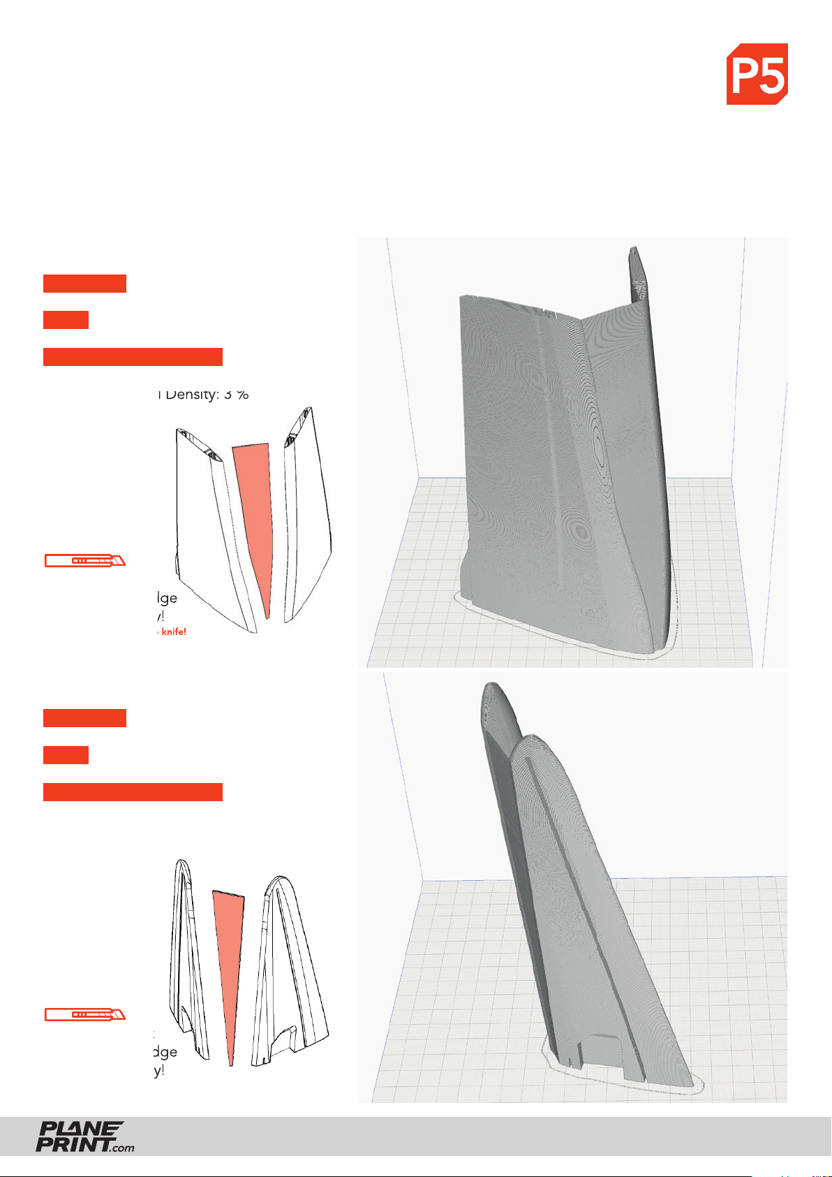
P5_Wings 2-fn.rstl
MATERIAL LW PLA, Weight: ~ 43 g
TIME ~ 7 hours 30 minutes
ADDITIONAL SETTINGS
• Infi ll Density/Fill Density: 3 %
Remove support
and round the edge
of the nose nicely!
Please be careful with the knife!
P5_Wings 3-fn.stl
MATERIAL LW PLA, Weight: ~ 21 g
TIME ~ 3 hours 40 minutes
ADDITIONAL SETTINGS
None required
Remove support
and round the edge
of the nose nicely!
Please be careful with the knife!
FALCON
PRINTING & ASSEMBLING MANUAL
© PLANEPRINT
24
Page 25
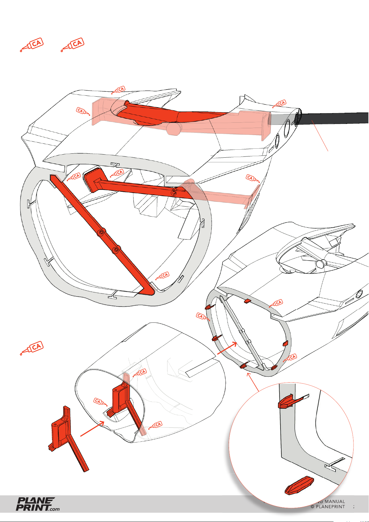
Body assembly
Align the center part using the carbon tubes so that they are correctly
positioned in the body, then remove the tubes and run thin CA glue into all
joint surfaces. These parts must be very well fi xed.
medium liquid
thin liquid
If the carbon tubes are stiff, move them back and forth until the hole is
adjusted. They should be precise but easy to insert. They must not be glued!
P1_Center parts-fn.stl
P5_Body 1-fn.stl
Carbon tube Ø6*310mm
P1_Center parts-fn.stl
medium liquid
P1_Tail joint 1-fn.stl
P1_Parts-fn.stl
P5_Body 2-fn.stl
New improved
T-shaped
interconnects
FALCON
P1_T-connects-gi.stl
PRINTING & ASSEMBLING MANUAL
© PLANEPRINT
25
Page 26
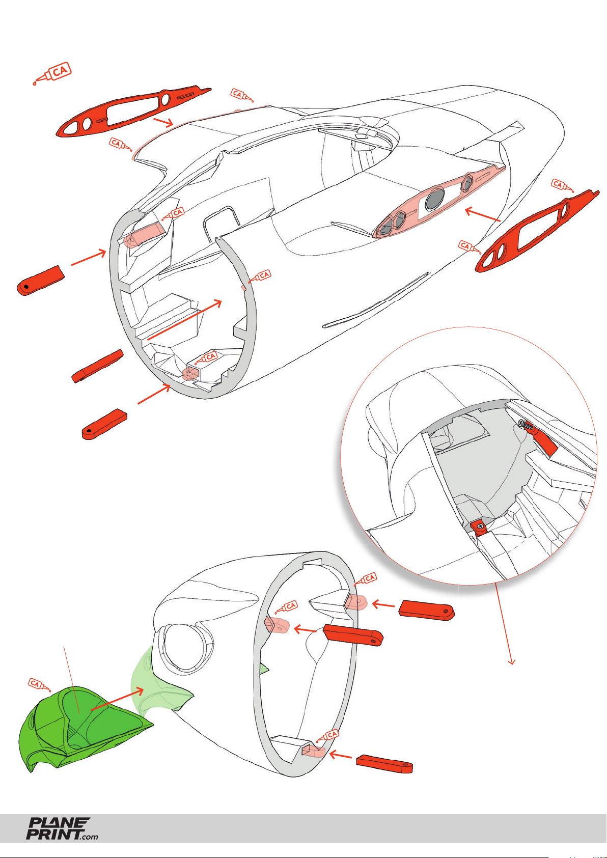
Body assembly
medium liquid
P5_Body 1-fn.stl P1_Protectors-fn.stl
P1_Head mount-fn.stl
Head assembly
Here is an example of the glider head:
Space for lead
P1_Head mount-fn.stl
P4_Beak-fn.stl
FALCON
P5_Head glider-fn.stl
Fasten the head to the
body with three short
tapping screws. So you
can switch between
glider and motor
version at any time.
PRINTING & ASSEMBLING MANUAL
© PLANEPRINT
26
Page 27
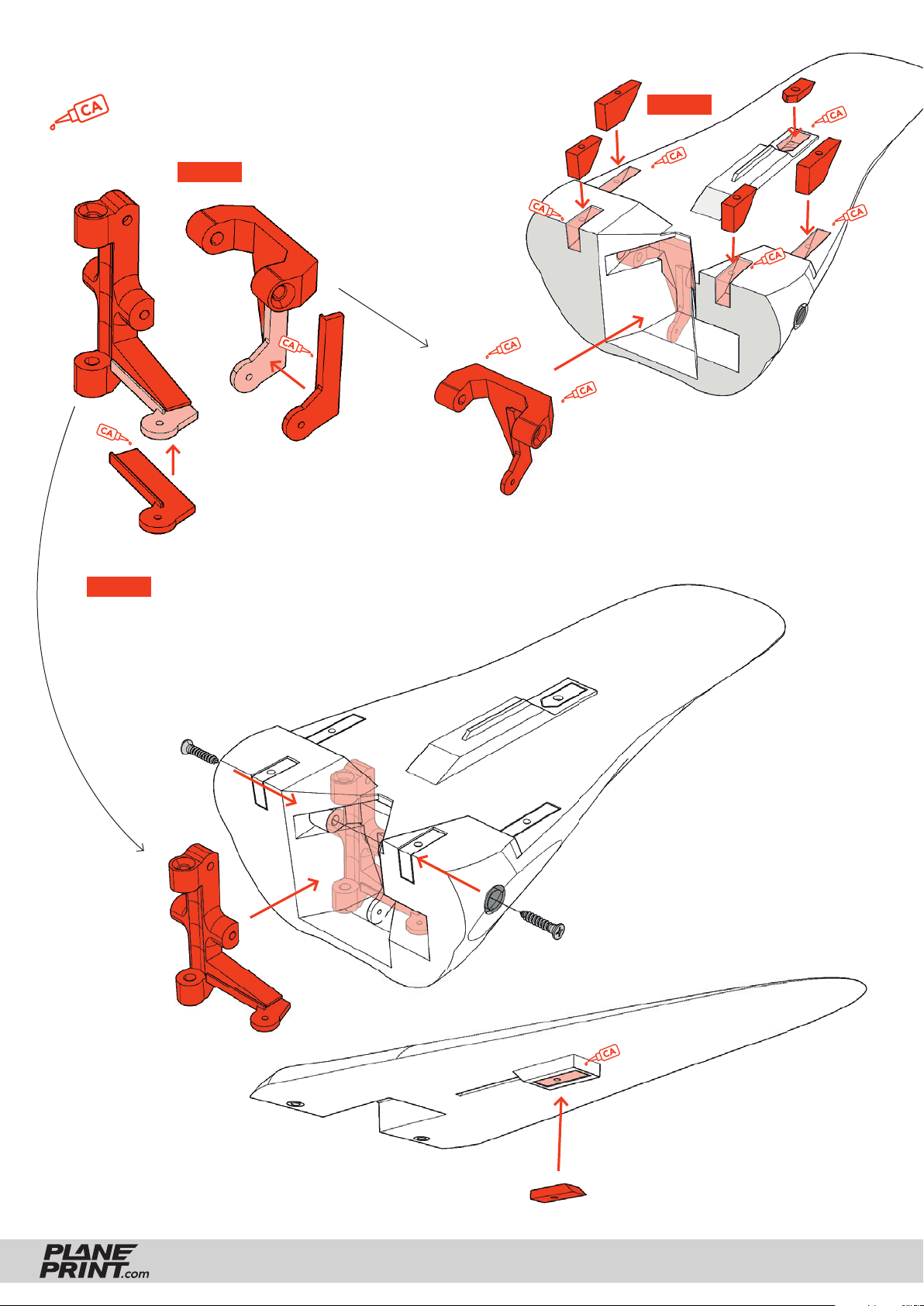
Tail assembly
medium liquid
P1_Parts-fn.stl
STEP 2
STEP 1
P1_Tail joint 2-fn.stl
P5_Tail base-fn.stl
Make sure that no glue runs into
the screw holes.
STEP 3
First screw the two screws all the way in and
then slightly back so that the joint (elevator)
is precise but smooth-running.
FALCON
P1_Parts-fn.stl
PRINTING & ASSEMBLING MANUAL
P5_Tail rigid foam-fn.stl
or
P5_Tail rigid glass-fn.stl
P5_Tail spread foam-fn.stl
P5_Tail spread glass-fn.stl
© PLANEPRINT
27
Page 28
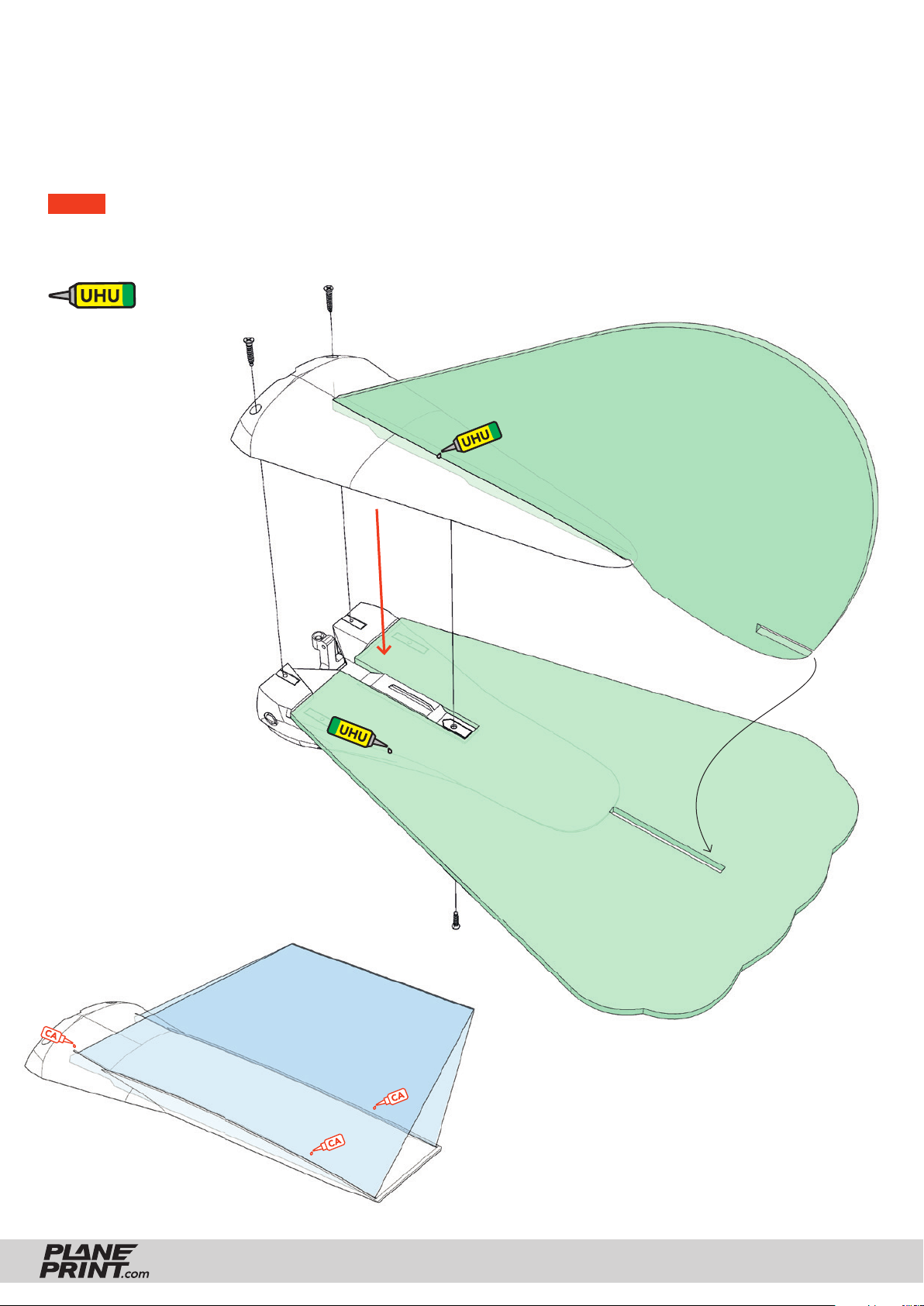
Tail assembly – rigid version
This tail version is the simplest and lightest. If you want to build the version with movable feathers,
skip this page.
NOTE For Depron use UHU POR, other adhesives will damage the
material. It is also suitable for other types of foam. UHU POR is a contact
adhesive. Coat both adhesive surfaces (foam and LW PLA) with adhesive
and wait until it is dry. Then join the parts together.
Glue the foam elevator
onto the tail base and
the foam rudder into the
upper part.
To assemble, fi rst
insert the rudder into
the slot at the back of
the elevator and fi x
everything with three
tapping screws.
You can swap the rudder
for another version at
any time.
P5_Tail rigid foam-fn.stl
Rudder Foam rigid version
P5_Tail rigid glass-fn.stl
Rudder
Overhead transparency version
FALCON
Elevator Foam rigid version
The glass version is visually less conspicuous than
the foam rudder, but somewhat heavier and less
stabilizing in fl ight.
Fold the rudder at the top and insert it into the
slots of the tail part. Allow thin CA glue to run into
the slots and do not use activator spray to prevent
clouds from forming.
PRINTING & ASSEMBLING MANUAL
© PLANEPRINT
28
Page 29
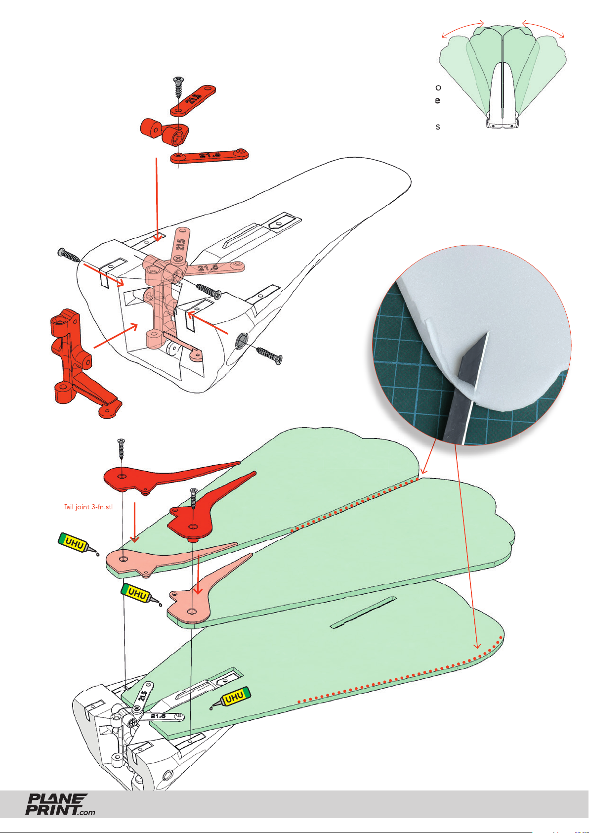
Tail assembly – Spreadable version
First screw the
screws all the way
in and then slightly
back so that the
joint (elevator) is
precise but smoothrunning.
P1_Tail joint 3-fn.stl
In this version, the elevator
consists of three foam parts, two
of which are movable and move
apart when the elevator goes
up. There is also a foam or glass
rudder for this.
P1_Tail joint 3-fn.stl
Elevator spread version
Elevator spread version
Elevator spread version
For the movement of the feathers to work, the foam
must have a smooth surface! Bevel the edge slightly
at these points so that the foam parts cannot tilt.
FALCON
PRINTING & ASSEMBLING MANUAL
© PLANEPRINT
29
Page 30
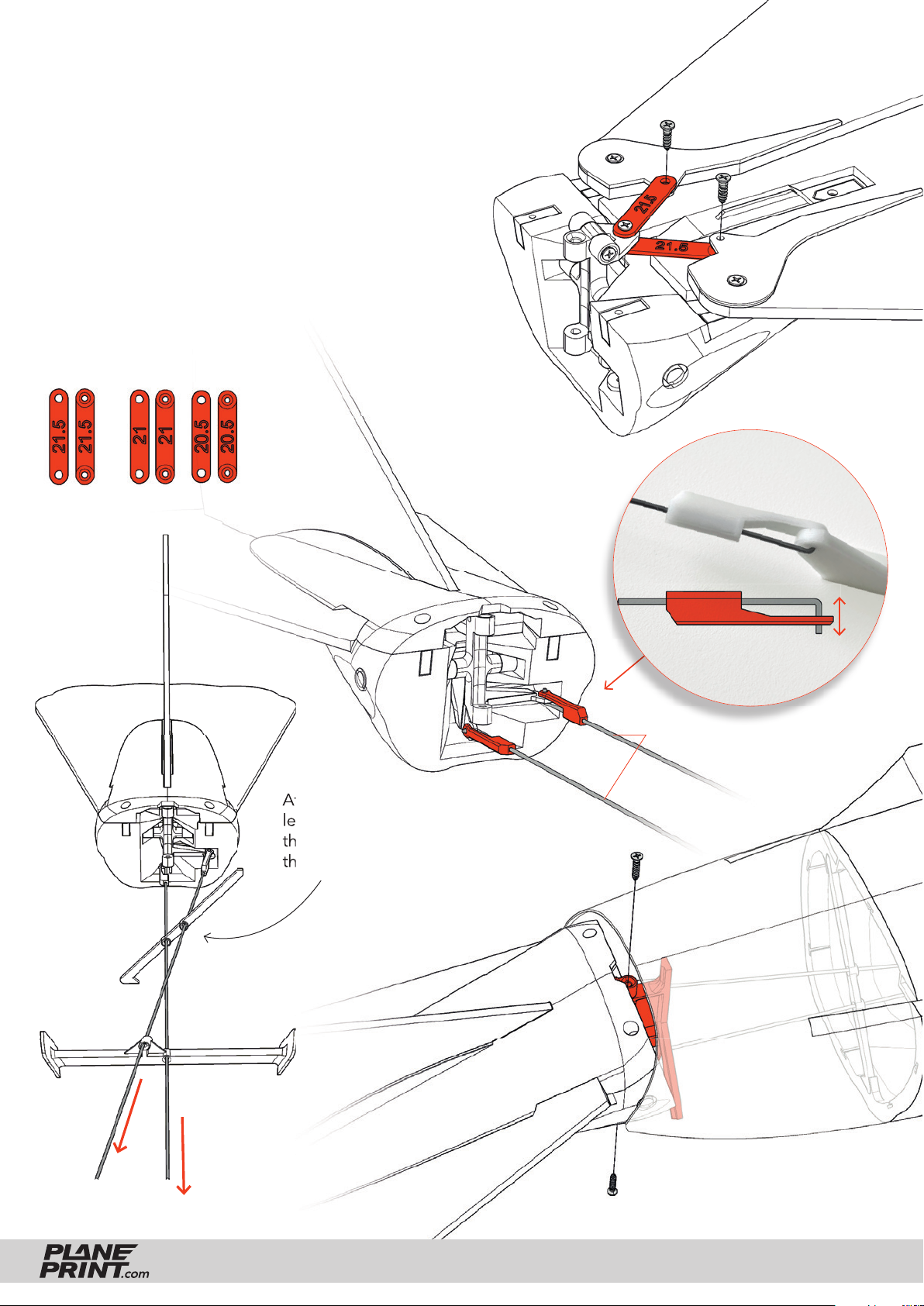
Tail assembly – Spreadable version
Finally, the two levers are connected to the expandable
elevators. All joints must run absolutely smoothly so as
not to put too much strain on the servo!
The two movable elevator parts touch each other when
the elevator is at the bottom, at the top they are spread
to the maximum. Check the process several times and
make sure that everything works smoothly, the function
of the elevator is essential in fl ight!
If the angles do not fi t, you can print the alternative
levers and try them out.
P1_Joint levers-fn.stl
Attach two steel wires to the
levers on the tail and insert
them through the guide holes in
the body (they must cross)
Steel Wire Ø1mm
5 mm
P1_Clips-fn.stl
Steel wires Ø1*300mm
FALCON
Attach the tail to the joint in the
body using two tapping screws.
PRINTING & ASSEMBLING MANUAL
© PLANEPRINT
30
Page 31
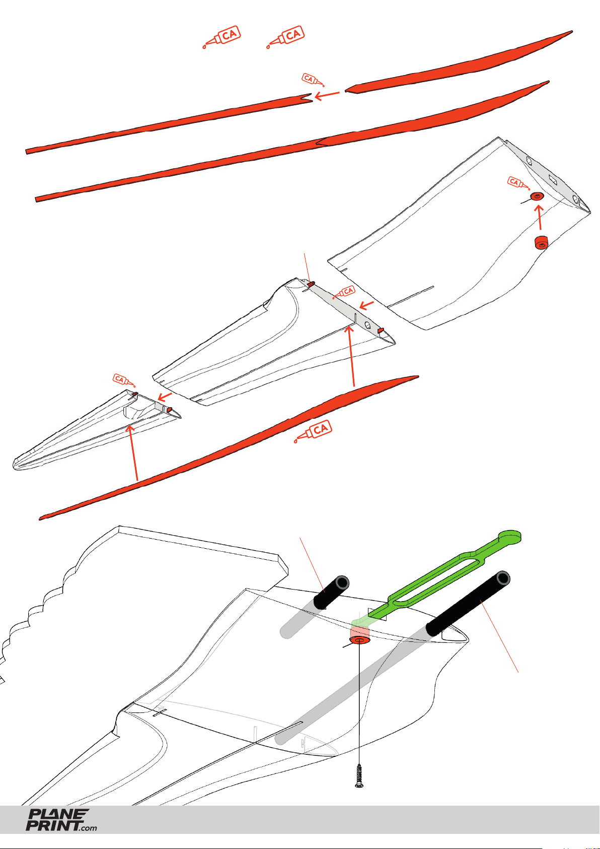
Wing assembly
First prepare the wing spars:
P1_Wing Spar-fn.stl
medium liquid thin liquid
Glue the wing parts together and
then insert the wing spar into the
slot at the bottom. Then let thin
CA glue run along the entire spar
to obtain a large-area bond.
P5_Wings 3-fn.stl
P1_Wing Spar-fn.stl
P1_T-connects-fn.stl
P5_Wings 2-fn.stl
Carbon tube Ø6*70mm
P1_Parts-fn.stl
P5_Wings 1-fn.stl
thin liquid
Screw the tension belt into the
wing and insert the carbon tubes.
They do not need to be glued.
FALCON
P4_Tension belt-fn.stl
PRINTING & ASSEMBLING MANUAL
Carbon tube Ø6*310mm
© PLANEPRINT
31
Page 32
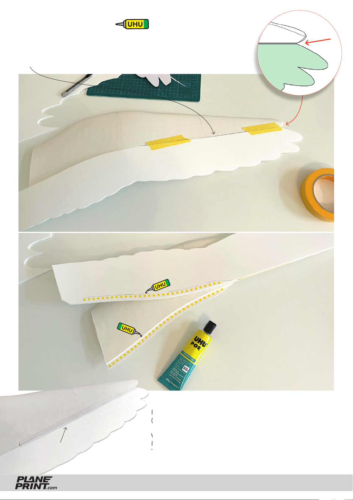
Wing assembly
Cut out the foam parts for the wing (Wing/Aileron) and temporarily fi x
them along the aileron with two strips of adhesive tape. Make sure that
a gap of 1 to 2 mm remains open for the later aileron hinge!
Align
here
Fabric strip
FALCON
... then fold the foam part over and
apply UHU POR to the wing and
foam and allow the glue to dry.
When the glue is dry, glue the
parts together.
Remove the adhesive tapes and cut a narrow stripe from fabric
(or use a tape for the hinges, it should be paintable).
Wet the fabric strip and the area along the hinge with UHU
POR, let it dry and then glue the strip to the wing and aileron.
The gap allows the outer part to move without a visible aileron.
PRINTING & ASSEMBLING MANUAL
© PLANEPRINT
32
Page 33
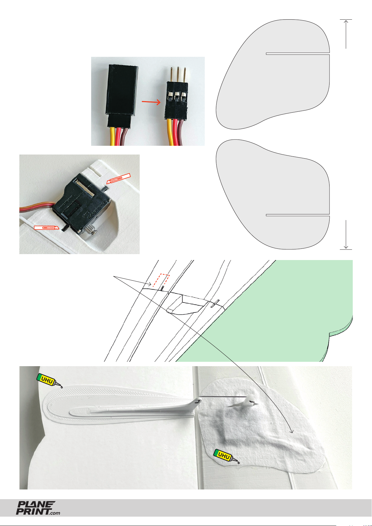
Wing Servo
You can cut off the
aileron servo cable
and solder on an
extension or use
an extension cable.
Because there is little
space in the narrow
wing, the outer sheath
must be removed
(carefully! with side
cutters or a knife).
Cut out two servo covers from fabric
according to this template:
Stick the servo
into the wing with
double-sided
adhesive tape or
wrap it with tape and
glue it with CA glue.
This length must measure exactly 130 mm
Here you can check whether the print is the exact size.
Carefully enlarge this opening
in the servo duct with a knife
until the servo cable plug fi ts
through.
Glue the control horn onto the
aileron as shown in the picture
below and fi nally, if everything
is set up correctly, the fabric
servo cover.
P1_AIL horns-fn.stl
P5_Wings 2-fn.stl
FALCON
PRINTING & ASSEMBLING MANUAL
© PLANEPRINT
33
Page 34
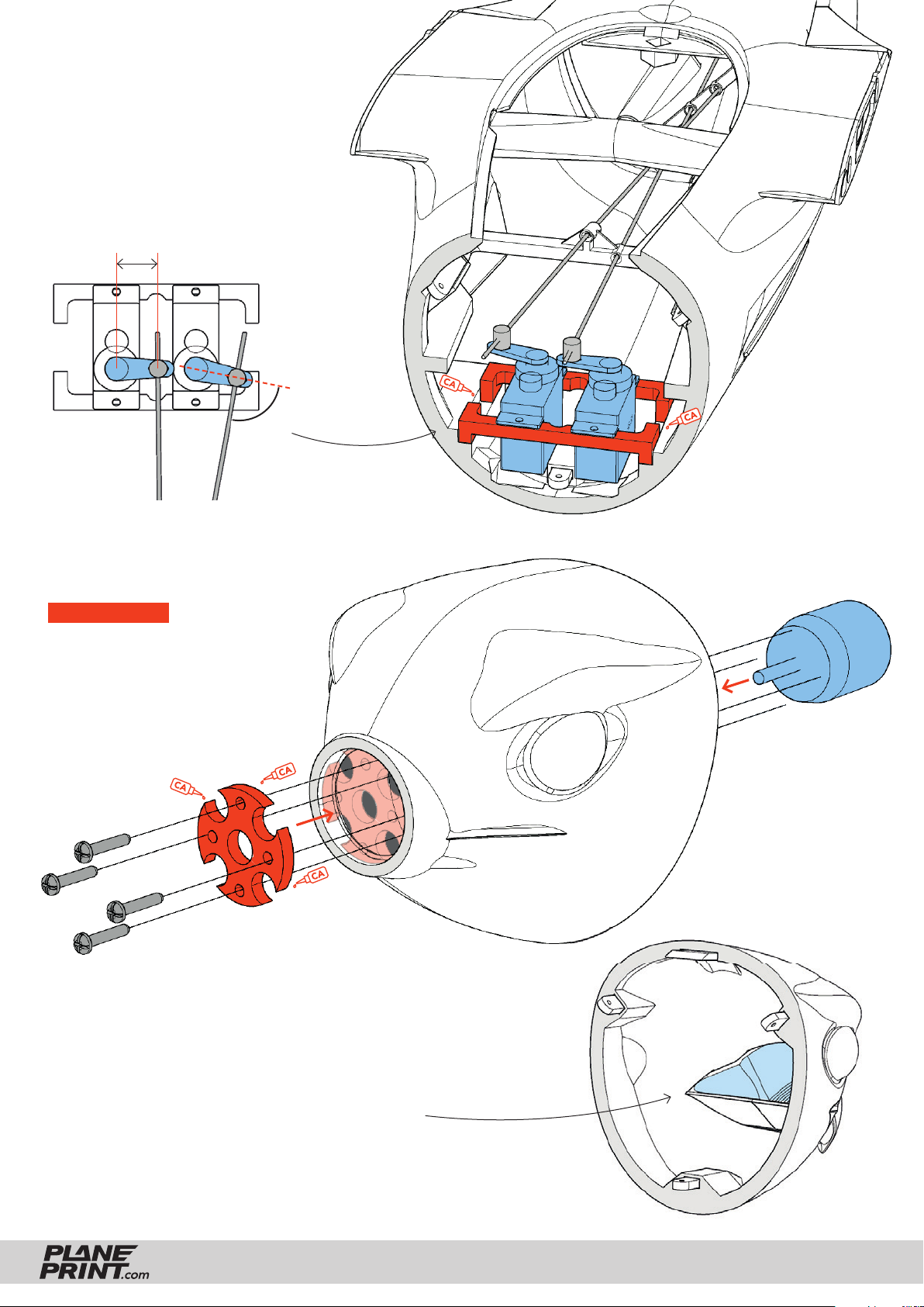
Fuselage Servos
Install the servos as shown in the
picture. Make the servo arms rather
short so that the entire angle of the
servo can be utilized (less load on
the servo)!
10 - 12 mm
Rudder
Elevator
Elevator
Rudder
90°
Motor mount
SAFETY FIRST Make sure the
prop does not generate vibrations.
Check regularly that the motor
mounting is tight!
P1_Parts-fn.stl
P5_Head motor-fn.stl
P1_Motor mount 16-19-fn.stl
Glider head
There is room for lead in the beak. Position the receiver
battery as far forward as possible to achieve the correct
CG in combination with the lead.
FALCON
PRINTING & ASSEMBLING MANUAL
© PLANEPRINT
34
Page 35
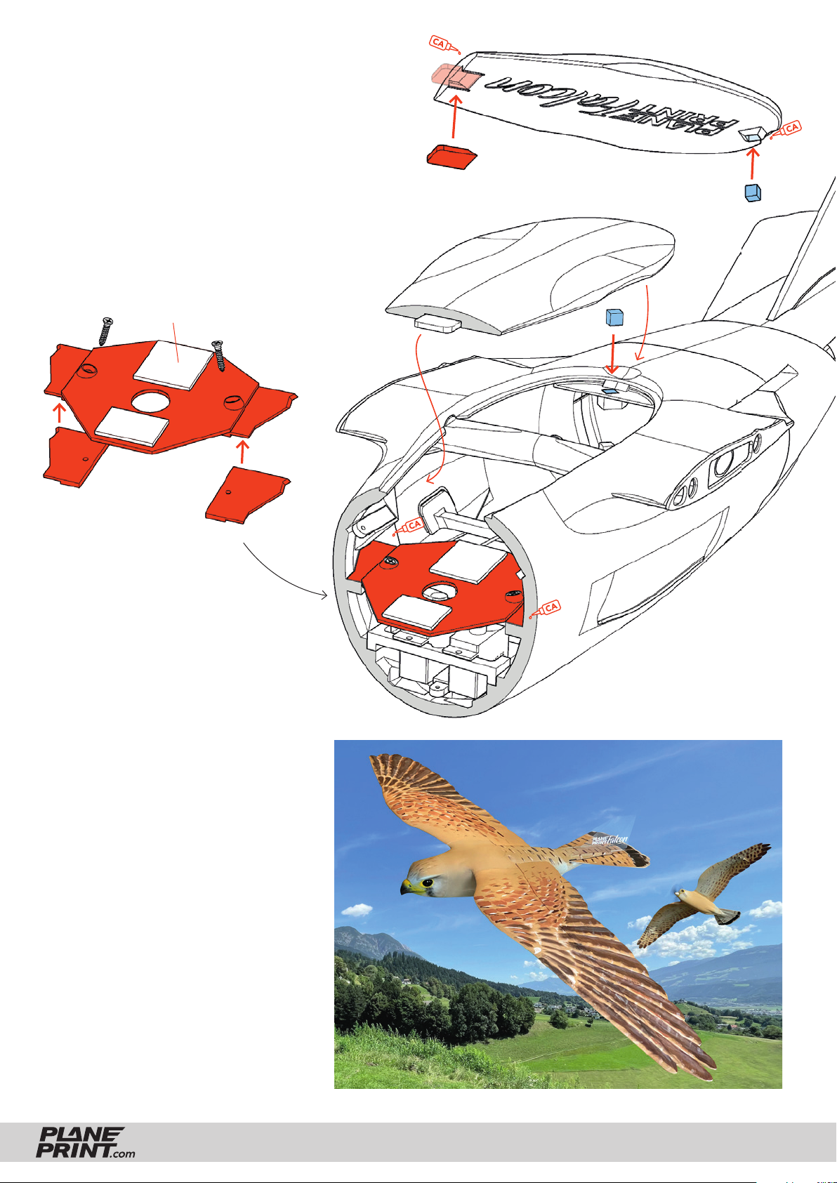
Cover
When gluing the magnets, make sure that they
are correctly aligned and do not repel each other.
You can put a piece of tape between the magnets
as a separator until the glue is fi rm.
Battery fastening
Velcro tape
P5_Cover-fn.stl
P1_Parts-fn.stl
Super magnet
Super magnet
P1_battery mount-fn.stl
Only glue the mounting base to
the body so that you can remove
the battery plate at any time.
Painting
I sprayed the base with two spray paints
(acrylic), light gray and light beige, very
thinly all over the bird. The plumage
was painted on with a fl at brush and
acrylic paints. Make sure that the paint
is rather dry, this automatically gives a
realistic effect. I used dark brown, a little black for blending and white. Yelloworange for the beak area. The eyes are
simply painted black and then painted
several coats of high-gloss varnish (or
nail varnish).
It is an advantage if you do not use
colors that are too dark, otherwise you
will have to protect the bird from direct
sunlight on warm days (the PLA can
become soft!). This is usually not a
problem with light colors.
FALCON
PRINTING & ASSEMBLING MANUAL
© PLANEPRINT
35
Page 36
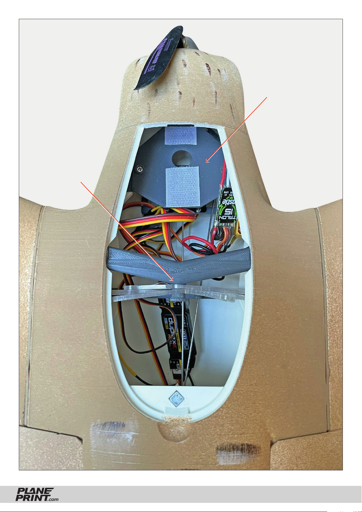
The tension belts
are attached here
Here you can move
the battery forwards or
backwards until the CG fits.
FALCON
PRINTING & ASSEMBLING MANUAL
© PLANEPRINT
36
Page 37
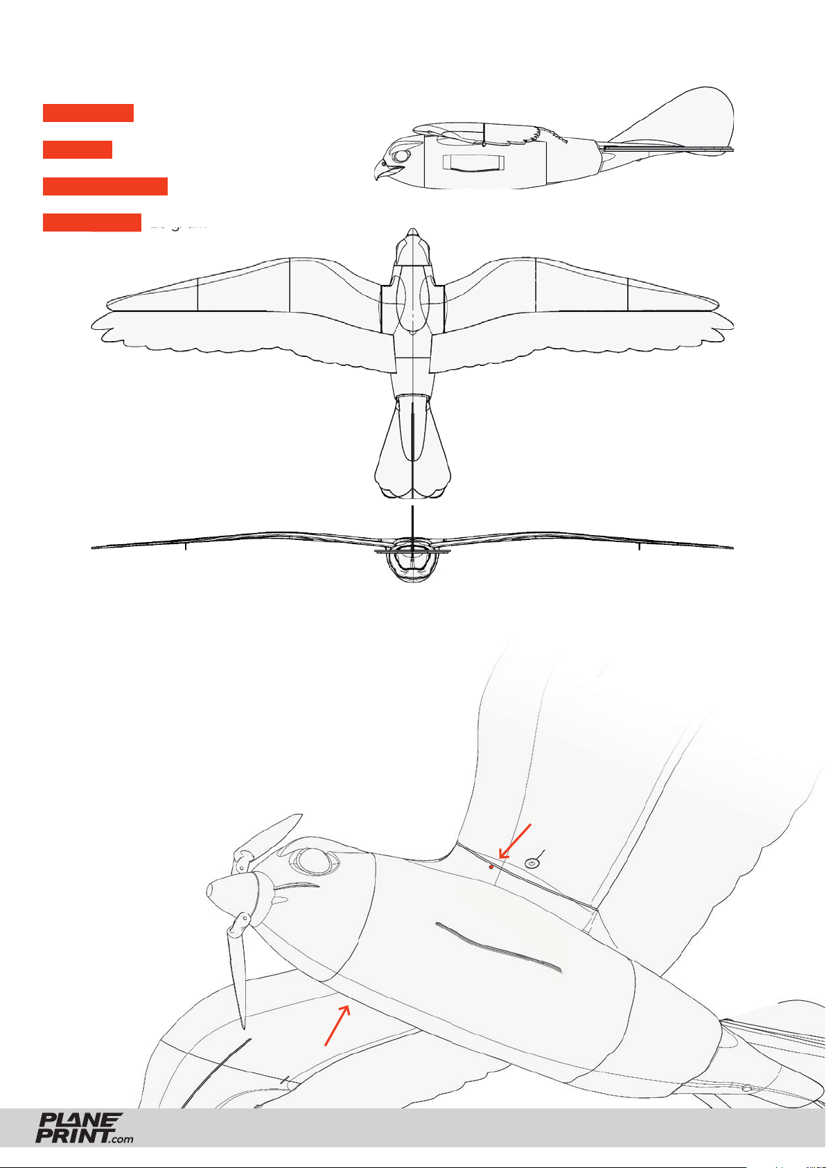
Technical specifi cations
WINGSPAN 1400 mm/55.1 inches
LENGTH 586 mm/23 inches
FLIGHT WEIGHT ~ 520 grams
WING LOAD 20 g/dm
2
Center of Gravity (CG)
The bird must balance on these points – see the markings
on the body. (28 mm/1.1 inch behind the leading edge)
Do not forget to check if the wings are exactly in ballance in
the roll axis. If one wing is heavier, correct this with a small
weight on the wingtip.
FALCON
PRINTING & ASSEMBLING MANUAL
© PLANEPRINT
37
Page 38
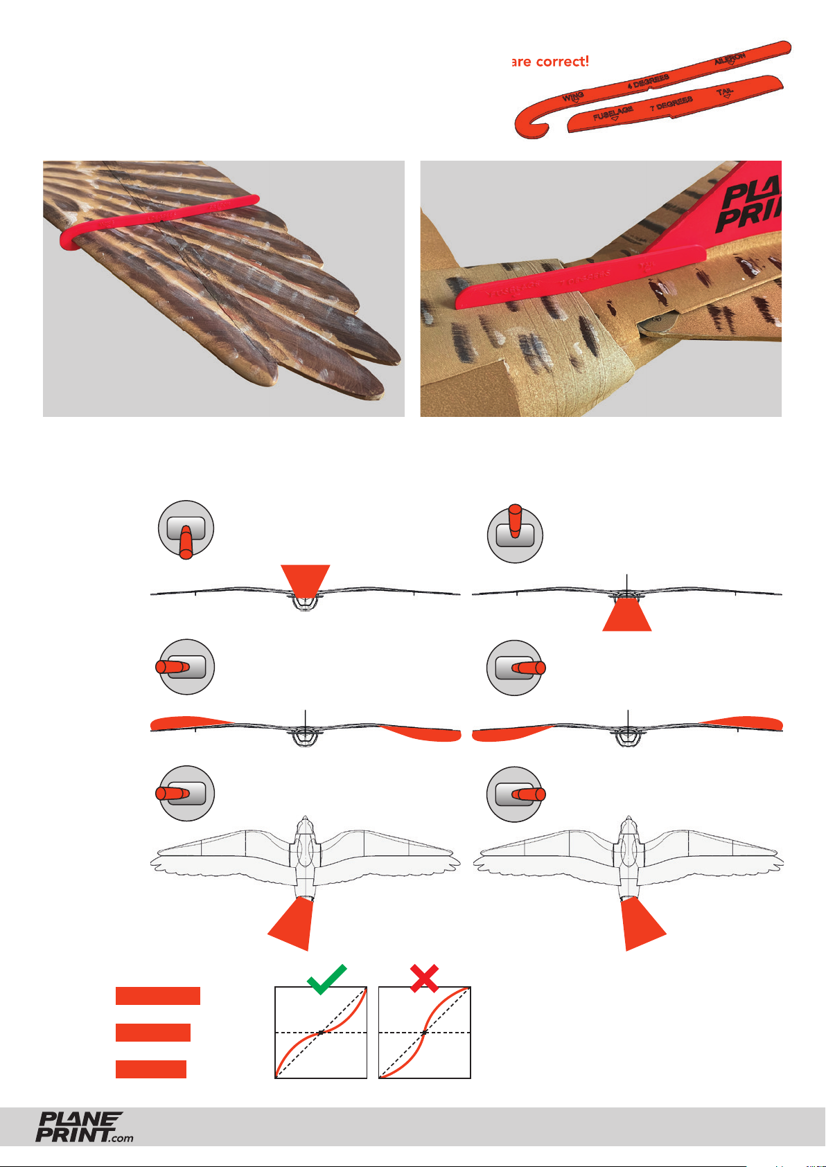
Basic setting It is very important that these settings are correct!
Place the setting gauges on the aileron at the height of the servo on
top of the wing and program the correct zero position. Likewise between body and elevator.
Any deviation
from this setting
changes the entire
wing characteristic!
P1_Setting gauges-fn.stl
Control Direction Test Set a normal aircraft (no Delta). Look from behind!
ELEVATOR
55 mm up
55 mm down
AILERON
15 mm up
15 mm down
RUDDER
60 mm left
60 mm right
EXPO
ELEVATOR 30 %
AILERON 20 %
RUDDER 0 %
FALCON
(for some remote
controls a minus
has to be in front
of the number)
PRINTING & ASSEMBLING MANUAL
© PLANEPRINT
38
Page 39

Flying tips
HAND LAUNCH
To start from the hand with the motor version, you
should give about half throttle and only increase the
throttle after a few meters. Despite the large downward correction angle of the engine, the Falcon pulls
up slightly when it gets fast. You have to be prepared
to correct a little with the elevator. We do not recommend a fixed correction program, as the effect becomes more pronounced the faster the bird flies.
Throw it upwards at a flat angle (10 to 20 degrees)
and make sure that it does not have a sideways effect
when released from the hand.
Be careful around the propeller area!
LANDING
The Falcon has the positive characteristic that it does
not stall over the wing in the event of a stall, but
only goes into a descent by turning the nose further
and further down. It still flies even with the elevator
fully pulled. You can recognize this flight condition
by the many small pitching movements, which are a
series of micro-stalls.
It is therefore important for the landing to give a
little more speed on the final approach to ensure
enough energy to recover before ground contact.
Especially on a slope, when landing with a tailwind,
you must be careful not to approach too slowly.
WHICH TAIL VERSION IS THE BEST?
The transparent foil rudder looks better than the
foam version, but is much heavier and requires significantly more weight at the front due to the long lever
and short neck of the Falcon. It is also slightly smaller
than the foam rudder and therefore does not stabilize
quite as well.
If you want maximum flying fun, including acro maneuvers, we recommend using the foam rudder.
If the main aim is to get as close as possible to the
image of a real animal, the glasrudder is an advantage.
It can therefore be easily changed at any time with
three screws. But don‘t forget to always pay atten-
tion to the correct CG!
Please be aware of wildlife and fly the Falcon
only in areas where it is allowed!
FALCON
PRINTING & ASSEMBLING MANUAL
© PLANEPRINT
39
Page 40

AGE RECOMMENDATION 14+
NOT FOR CHILDREN UNDER 14 YEARS.
THIS IS NOT A TOY!
The STL data (or data processed from it, such as G codes)
must never be passed on to third parties!
The purchase of the STL does not authorize the production
of models for third parties.
By using the download data, an RC model airplane, called
„model“ for short, can be manufactured using a 3D printer.
As a user of this model, only you are responsible for safe
operation that does not endanger you or others, or that
does not damage the model or property of others.
PLANEPRINT.com assumes no responsibility for damage to
persons and property caused by pressure, transport or use
of the product. Filaments, printing supplies, hardware or
consumables that can not be used after faulty 3D printing
will not be replaced by PLANEPRINT.com in any way.
When operating, always keep a safe distance from your
model in all directions to avoid collisions and injuries.
This model is controlled by a radio signal. Radio signals can
be disturbed from outside without being able to influence
it. Interference can lead to a temporary loss of control.
Always operate your model on open terrains, far from cars,
traffic and people.
Keep all chemicals, small parts and electrical components
out of the reach of children.
Avoid water contact with all components that are not specially
designed and protected. Moisture damages the electronics.
Never take an item of the model or accessory in your mouth
as this can lead to severe injuries or even death.
Never operate your model with low batteries in the transmitter or model.
Always keep the model in view and under control.
Use only fully charged batteries.
Always keep the transmitter switched on when the model
is switched on.
Always remove the battery before disassembling the model.
Keep moving parts clean and dry at all times.
Always allow the parts to cool before touching them.
Always remove the battery after use.
Make sure that the Failsafe is properly set before the flight.
Always follow the instructions and warnings for this product
and any optional accessories (servos, receivers, motors,
propellers, chargers, rechargeable batteries, etc.) carefully.
We develop our models to the best of our knowledge and belief.
We accept no liability for consequential damage and injuries
caused by improper use or incorrectly printed parts. Please be
careful when handling motors, batteries and propellers and
only move your model with insurance and in approved places!
Never operate the model with damaged wiring.
Never touch moving parts.
© PLANEPRINT.com, A-6021 Innsbruck, Conradstraße 6, [email protected]
© Design STL files by René Marschall • Layout: marschall designlab, marschall.cc
 Loading...