

Page 1
NOTE: Slicing only
works with CURA!
You can fi nd the STL data
at www.planeprint.com
PRINTING & ASSEMBLING MANUAL
Page 2
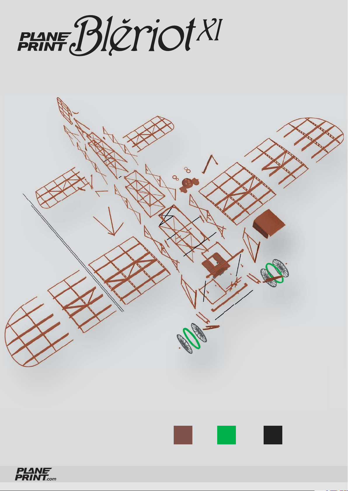
PLA TPU CARBON
BLÉRIOT XI
PRINTING & ASSEMBLING MANUAL
© PLANEPRINT
2
Page 3
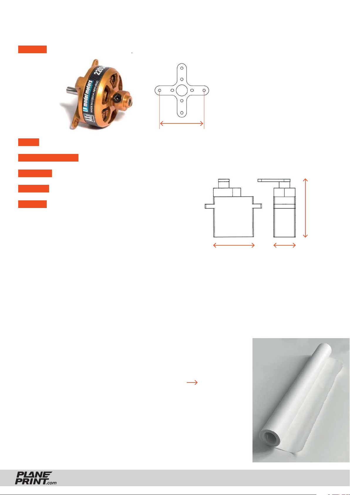
RC Components
ENGINE AXI 2203/40 VPP or comparable indoor-20 grams-motors.
PROP 8x3.8 or comparable, also possible 8x3, 8x4
BEC-CONTROLLER 15 A (one matching the motor)
RECEIVER 3 Channel
BATTERY 2S Lipo, 650 MaH (ideal weight 38 grams)
SERVOS • Stemedu Micro 3.7g Servo GH-S37D
• PLANET-HOBBY ECO PLUS
• PICCO 8 DIGITAL SERVO
• Diamond D47
• Hitec HS 40 Eco Servo 4,8g
or similar in the same size, 2 pieces
There are also ready-made indoor drive sets with motor, servos and battery available from many dealers.
31 mm
max. 22 mm
max. 27 mm
max. 8.5 mm
Required accessoires – basic equipment
• Tough PLA (or PLA), ~200 grams
• LW TPU like VarioShore, ~20 grams (or TPU A95)
• CA super glue (liquid and liquid medium or thick)
• CA activator
• Wood glue
• Carbon rod Ø2*1000mm, 1 piece
• Carbon rod Ø0.8*1000mm (also possible is Ø1mm), 2 pieces
• Steel wire Ø0.8mm (a few short pieces for the linkage)
• Parchment or tissue paper (or another light paper to cover the wings)
• black and gold acrylic paint and thin gray twine
• some tapping screws Ø2 mm
• Hair gums or small rubber bands
Tools
Cutter knife, Scissors, small Philips screwdriver, Sandpaper, small brush
BLÉRIOT XI
PRINTING & ASSEMBLING MANUAL
© PLANEPRINT
3
Page 4

Printing the parts – Printing profiles
This manual is constantly being improved and supplemented, we recommend downloading
the latest version from our website before building.
For slicing all Planeprint
models, these profiles have
to be created in Cura:
PROFILE P1_Fullbody
PROFILE P2_Hollowbody
PROFILE P3_Surface
PROFILE P4_Flex
PROFILE P5_Gyroid
You can find the description at
www.planeprint.com/print
The Blériot XI requires :
Important for the
1-wall-print (P3, P5)!
In order to print airfoils of the lowest possible weight with high stability, it is necessary to print with only one wall line (Nozzle 0.4
mm). Decisive here is the adhesion between
the layers! To achieve this, you must print at
a much higher temperature than normal. As
a guideline, 230° C is a good starting point.
The parts-cooling fan should be set to 0% or
a maximum of 20%. Since not every printer
works the same, it may be necessary to make
small adjustments to these settings.
PROFILE P1_Fullbody, PROFILE P2_Hollowbody and PROFILE P4_Flex
The development of a complex, airworthy RC flight model to express on any standard 3D printer is a very complex and extensive process. Therefore, we appeal to
your fairness not to forward the STL data you have acquired to third parties.
Thank you for your understanding and have fun with your PLANEPRINT MODEL!
BLÉRIOT XI
PRINTING & ASSEMBLING MANUAL
© PLANEPRINT
4
Page 5
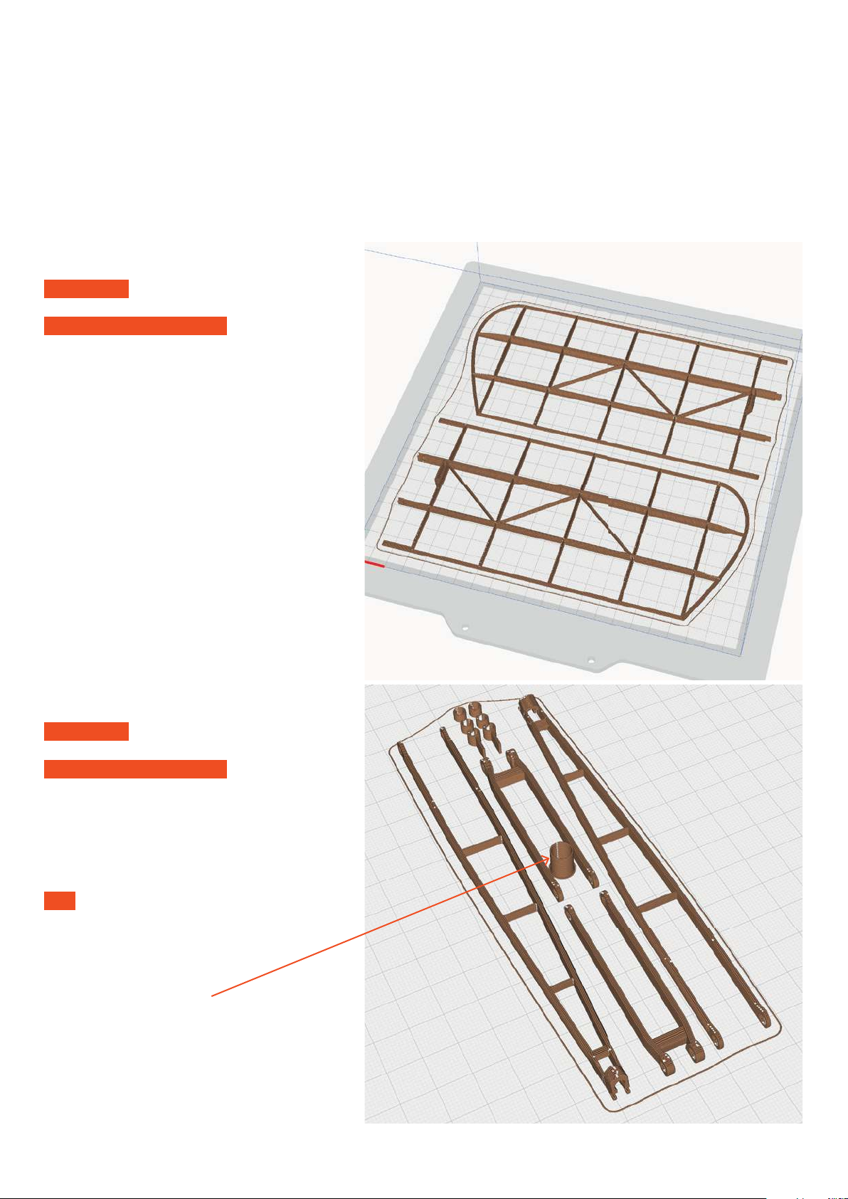
PROFILE P1_Fullbody
The following parts must be sliced with the PROFILE P1_Fullbody.
Please note the additional settings for the individual parts!
Tough PLA (or PLA)
P1_Elevator_bl.stl
MATERIAL PLA, Weight: ~ 10 g
ADDITIONAL SETTINGS
None required
P1_Gear_bl.stl
MATERIAL PLA, Weight: ~ 6 g
ADDITIONAL SETTINGS
None required
TIP These parts should be black, you can
paint them with acrylic paint or print them
with black fi lament.
This part is not needed
(serves to optimize the paths)
Page 6
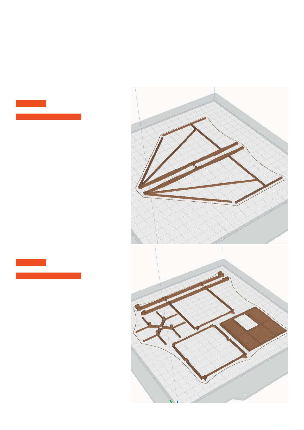
PROFILE P1_Fullbody
The following parts must be sliced with the PROFILE P1_Fullbody.
Please note the additional settings for the individual parts!
P1_Grid 1 side_bl.stl
MATERIAL PLA, Weight: ~ 7 g
ADDITIONAL SETTINGS
None required
Tough PLA (or PLA)
P1_Grid 1_bl.stl
MATERIAL PLA, Weight: ~ 15 g
ADDITIONAL SETTINGS
None required
Page 7
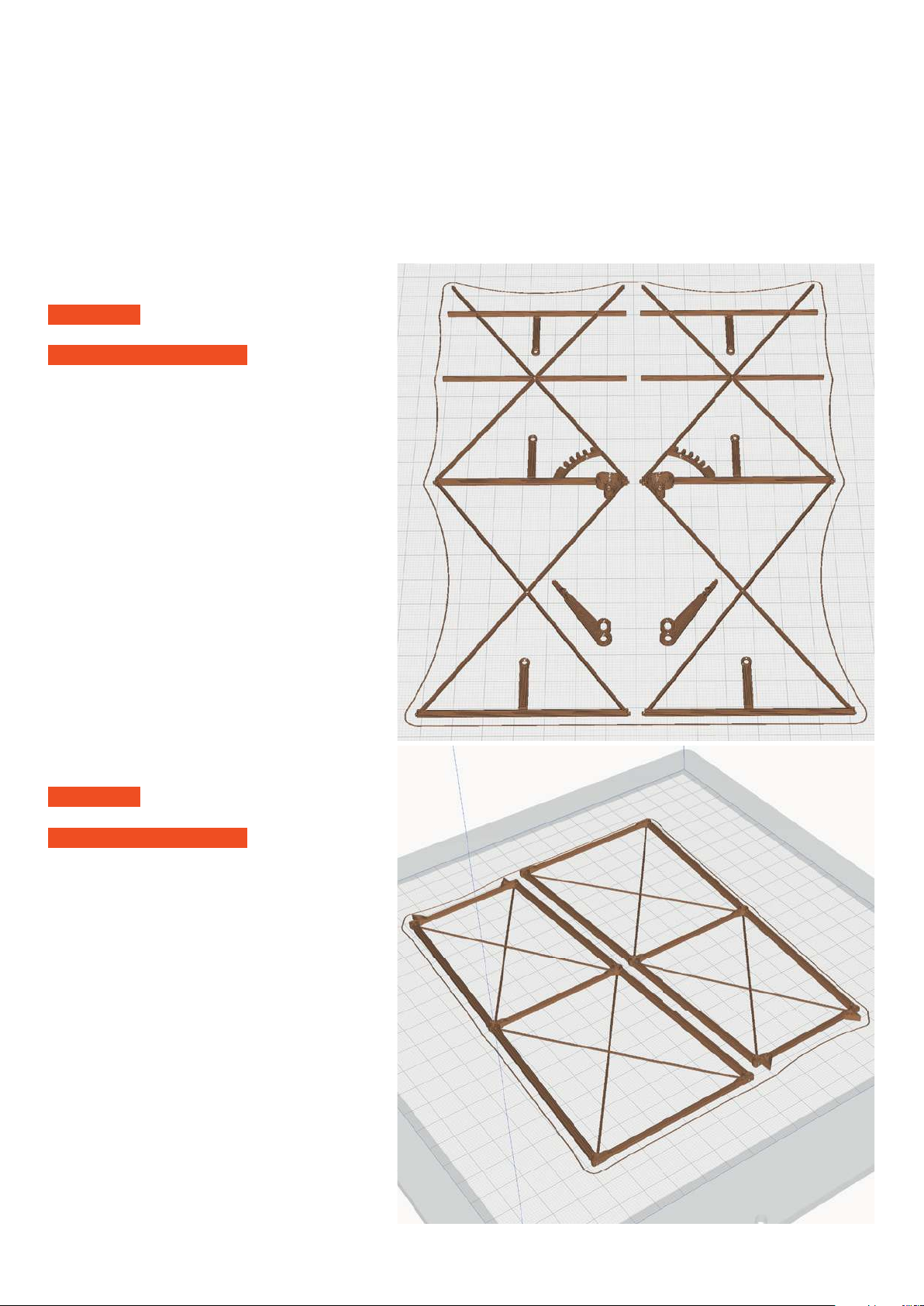
PROFILE P1_Fullbody
The following parts must be sliced with the PROFILE P1_Fullbody.
Please note the additional settings for the individual parts!
P1_Grid 2 side_bl.stl
MATERIAL PLA, Weight: ~ 6 g
ADDITIONAL SETTINGS
None required
Tough PLA (or PLA)
P1_Grid 2_bl.stl
MATERIAL PLA, Weight: ~ 10 g
ADDITIONAL SETTINGS
None required
Page 8
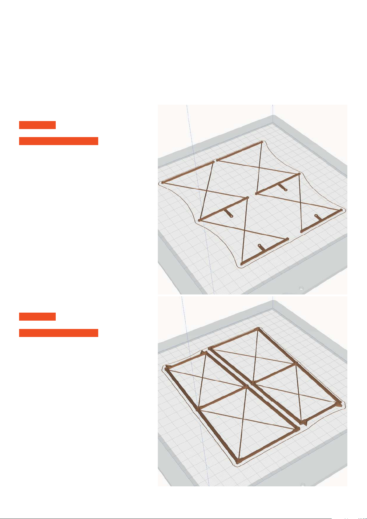
PROFILE P1_Fullbody
The following parts must be sliced with the PROFILE P1_Fullbody.
Please note the additional settings for the individual parts!
P1_Grid 3 side_bl.stl
MATERIAL PLA, Weight: ~ 3 g
ADDITIONAL SETTINGS
None required
Tough PLA (or PLA)
P1_Grid 3_bl.stl
MATERIAL PLA, Weight: ~ 8 g
ADDITIONAL SETTINGS
None required
Page 9
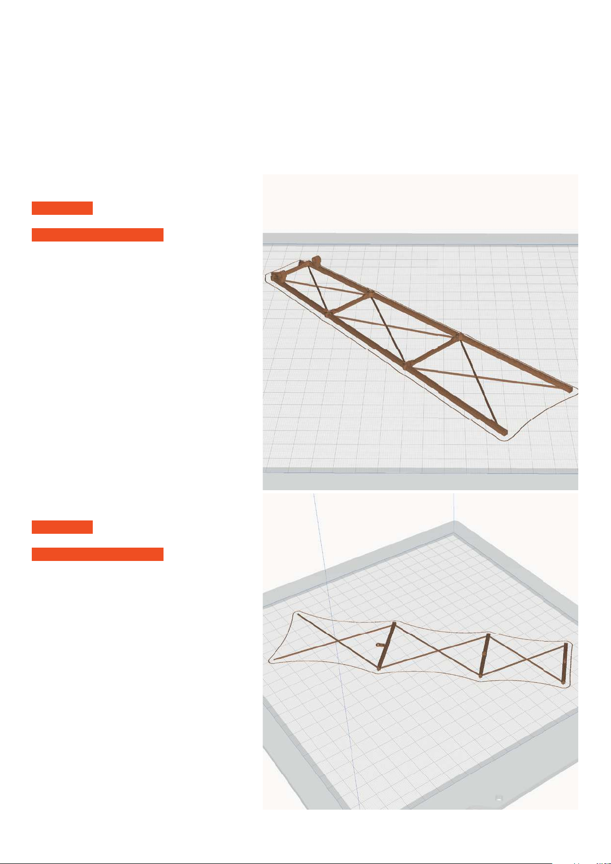
PROFILE P1_Fullbody
The following parts must be sliced with the PROFILE P1_Fullbody.
Please note the additional settings for the individual parts!
P1_Grid 4 down_bl.stl
MATERIAL PLA, Weight: ~ 4 g
ADDITIONAL SETTINGS
None required
Tough PLA (or PLA)
P1_Grid 4 side_x2_bl.stl
MATERIAL PLA, Weight: ~ 1 g
ADDITIONAL SETTINGS
None required
Page 10
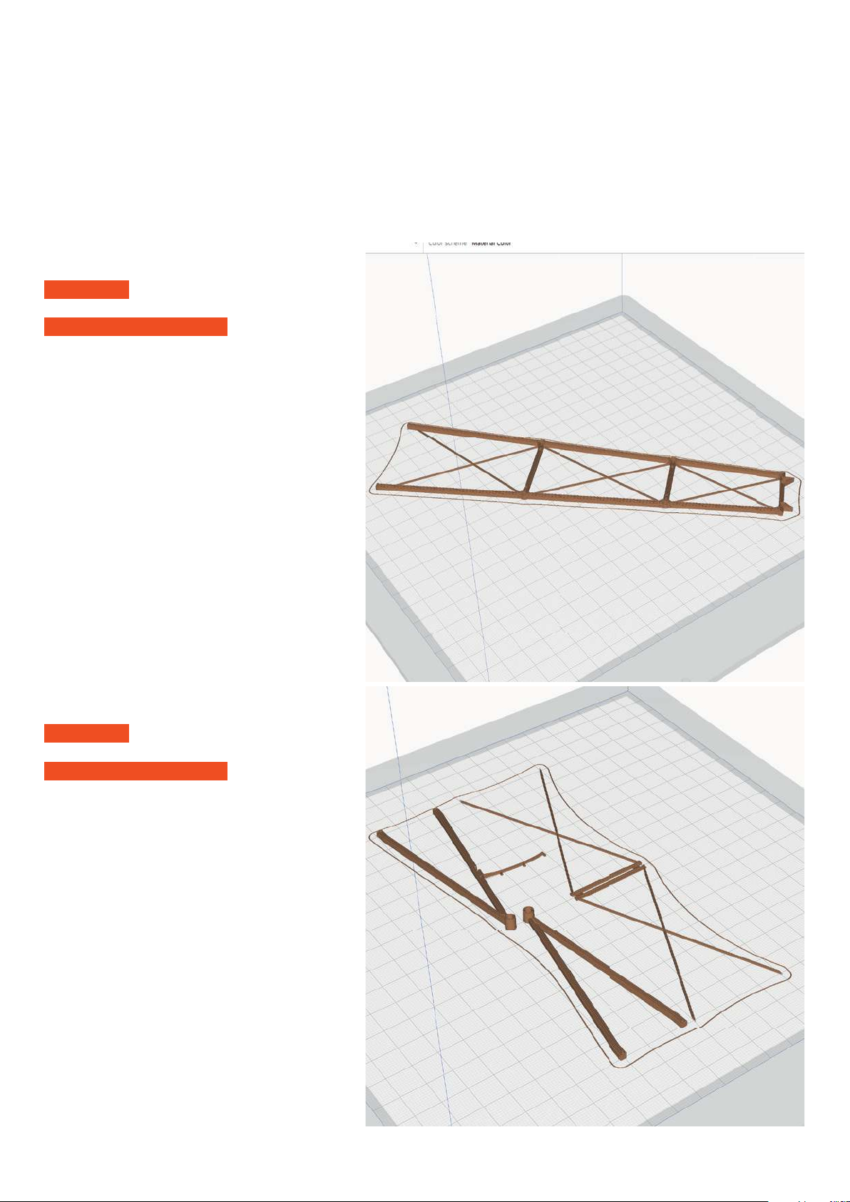
PROFILE P1_Fullbody
The following parts must be sliced with the PROFILE P1_Fullbody.
Please note the additional settings for the individual parts!
P1_Grid 4 up_bl.stl
MATERIAL PLA, Weight: ~ 4 g
ADDITIONAL SETTINGS
None required
Tough PLA (or PLA)
P1_Grid 5_bl.stl
MATERIAL PLA, Weight: ~ 3 g
ADDITIONAL SETTINGS
None required
Page 11
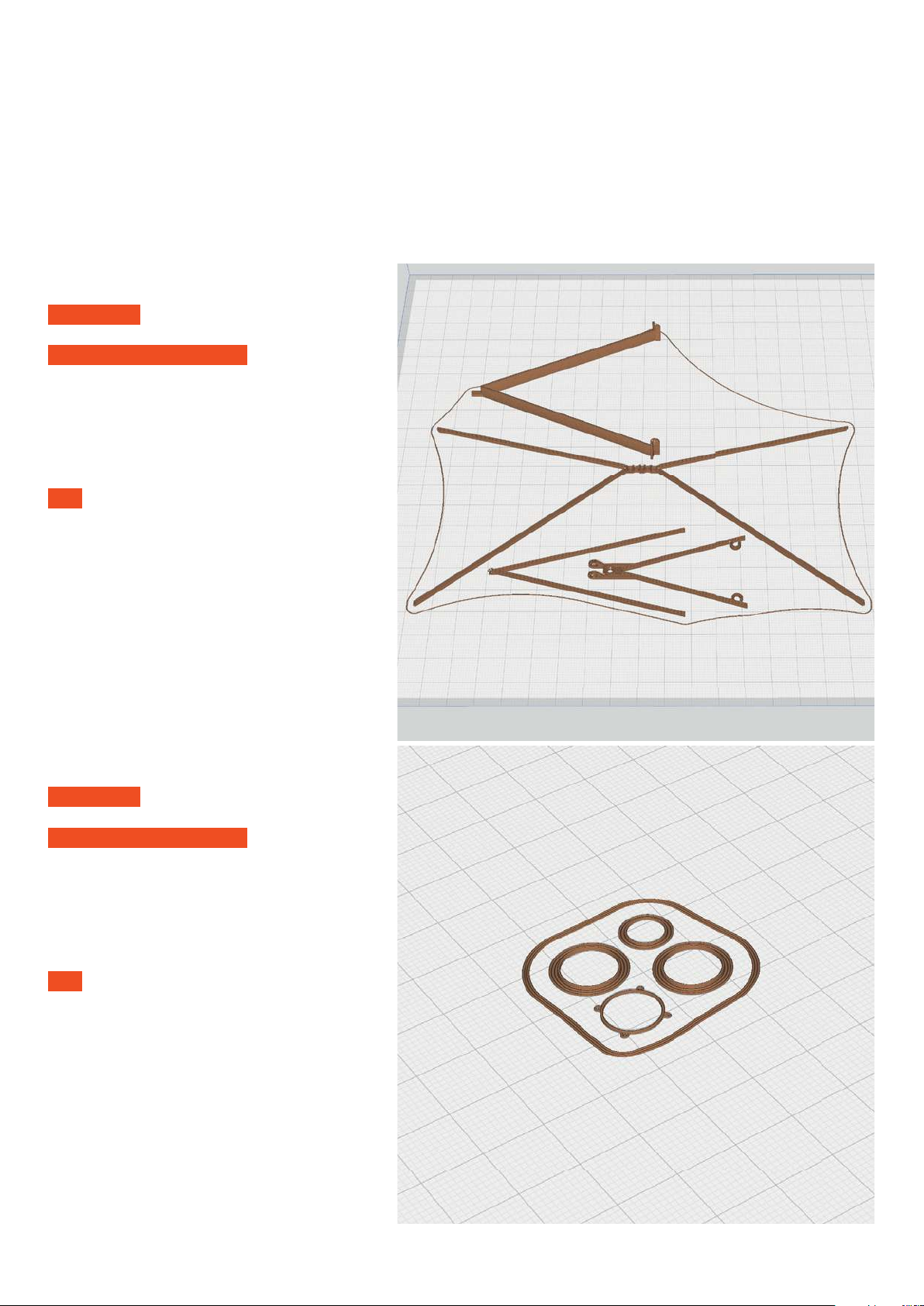
PROFILE P1_Fullbody
The following parts must be sliced with the PROFILE P1_Fullbody.
Please note the additional settings for the individual parts!
Tough PLA (or PLA)
P1_Grid parts_bl.stl
MATERIAL PLA, Weight: ~ 5 g
ADDITIONAL SETTINGS
None required
TIP These parts should be black, you can
paint them with acrylic paint or print them
with black fi lament.
P1_Instruments_bl.stl
MATERIAL PLA, Weight: ~ 0 g
ADDITIONAL SETTINGS
None required
TIP These parts should be black, you can
paint them with acrylic paint or print them
with black fi lament.
Page 12
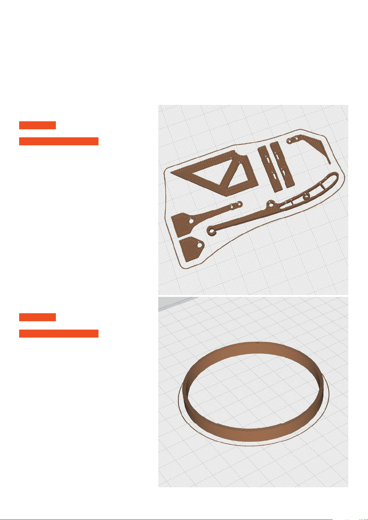
PROFILE P1_Fullbody
The following parts must be sliced with the PROFILE P1_Fullbody.
Please note the additional settings for the individual parts!
P1_Parts_bl.stl
MATERIAL PLA, Weight: ~ 3 g
ADDITIONAL SETTINGS
None required
Tough PLA (or PLA)
P1_Rim template_bl.stl
MATERIAL PLA, Weight: ~ 4 g
ADDITIONAL SETTINGS
None required
Page 13
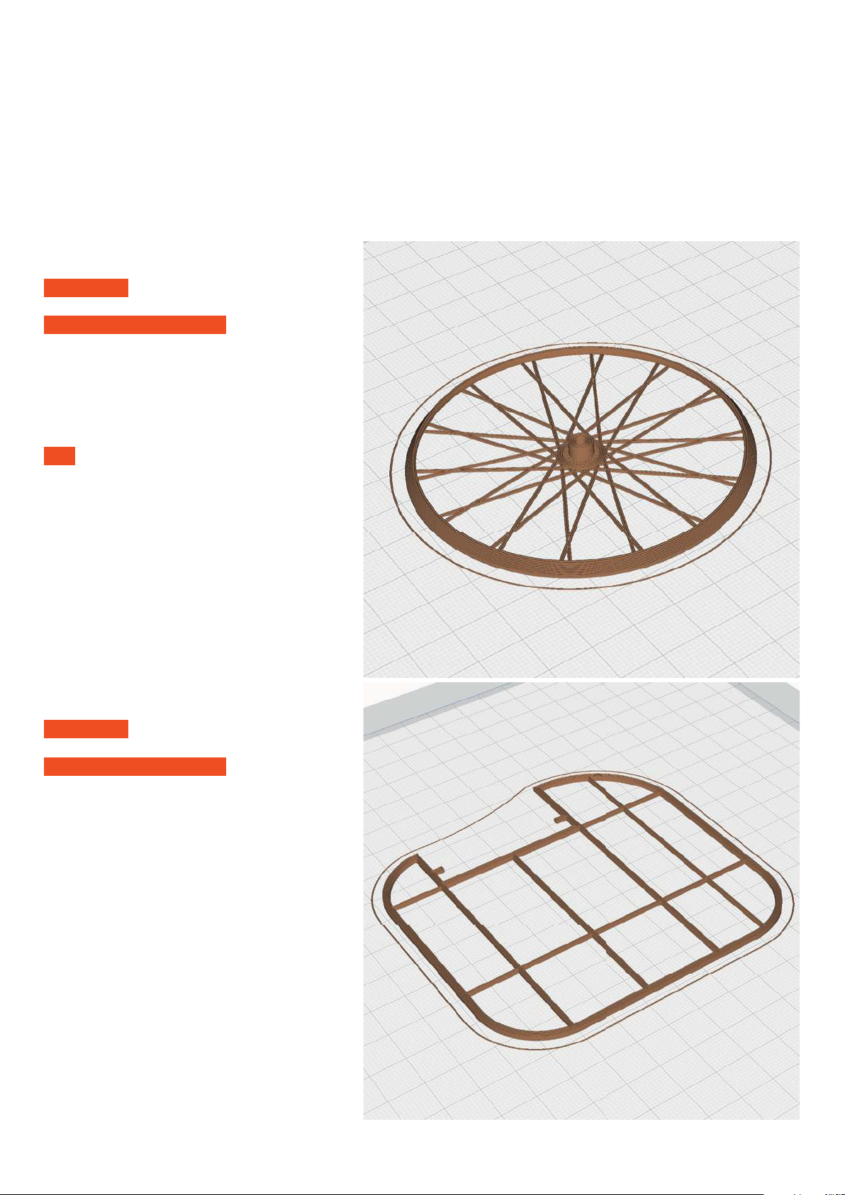
PROFILE P1_Fullbody
The following parts must be sliced with the PROFILE P1_Fullbody.
Please note the additional settings for the individual parts!
P1_Rim_x4_bl.stl
MATERIAL PLA, Weight: ~ 2 g
ADDITIONAL SETTINGS
None required
TIP use gray or silver fi lament
Tough PLA (or PLA)
P1_Rudder_bl.stl
MATERIAL PLA, Weight: ~ 2 g
ADDITIONAL SETTINGS
None required
Page 14
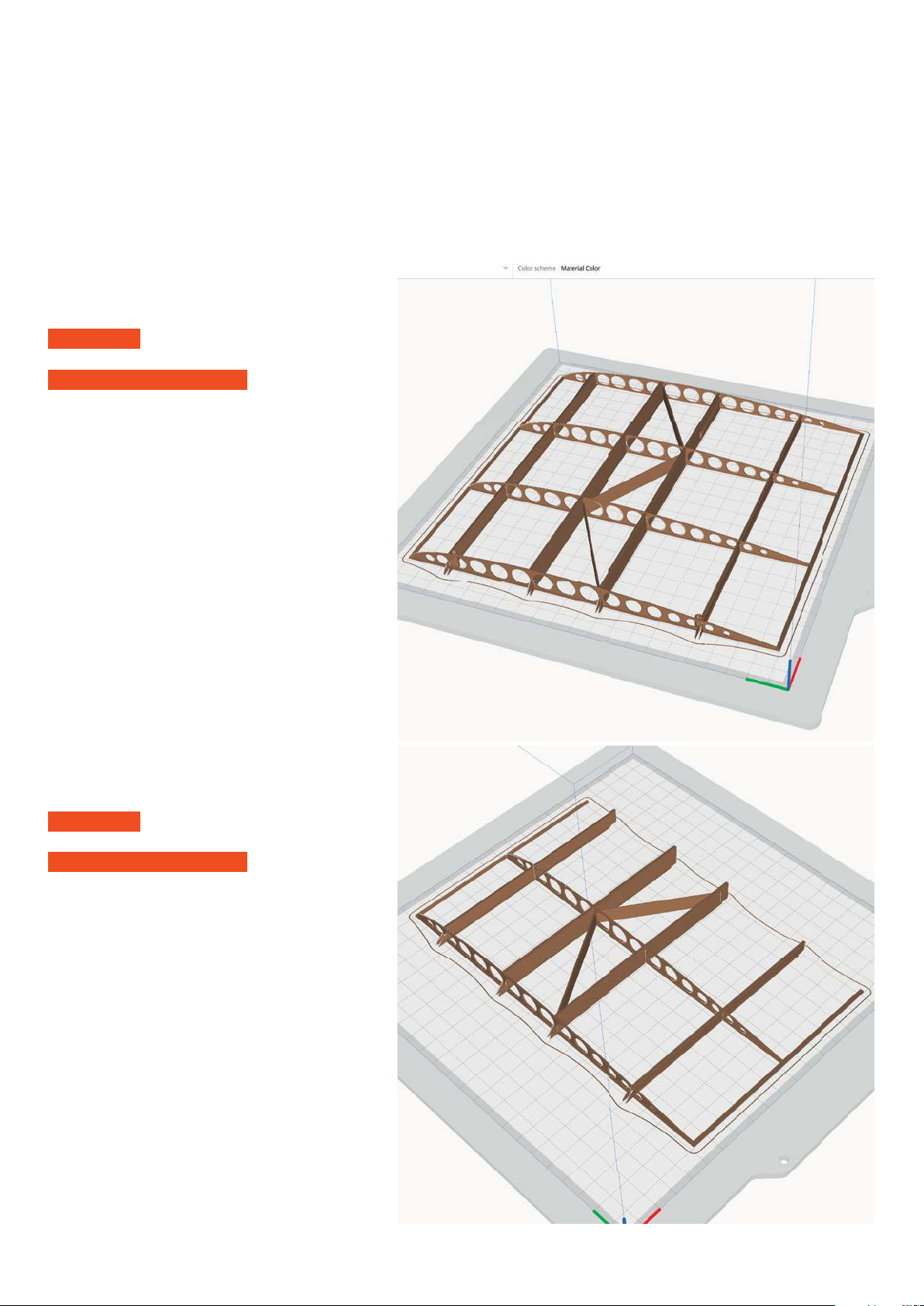
PROFILE P1_Fullbody
The following parts must be sliced with the PROFILE P1_Fullbody.
Please note the additional settings for the individual parts!
P1_Wing 1-L_bl.stl
P1_Wing 1-R_bl.stl
MATERIAL PLA, Weight: ~ 14 g
ADDITIONAL SETTINGS
None required
Tough PLA (or PLA)
P1_Wing 2-L_bl.stl
P1_Wing 2-R_bl.stl
MATERIAL PLA, Weight: ~ 8 g
ADDITIONAL SETTINGS
None required
Page 15
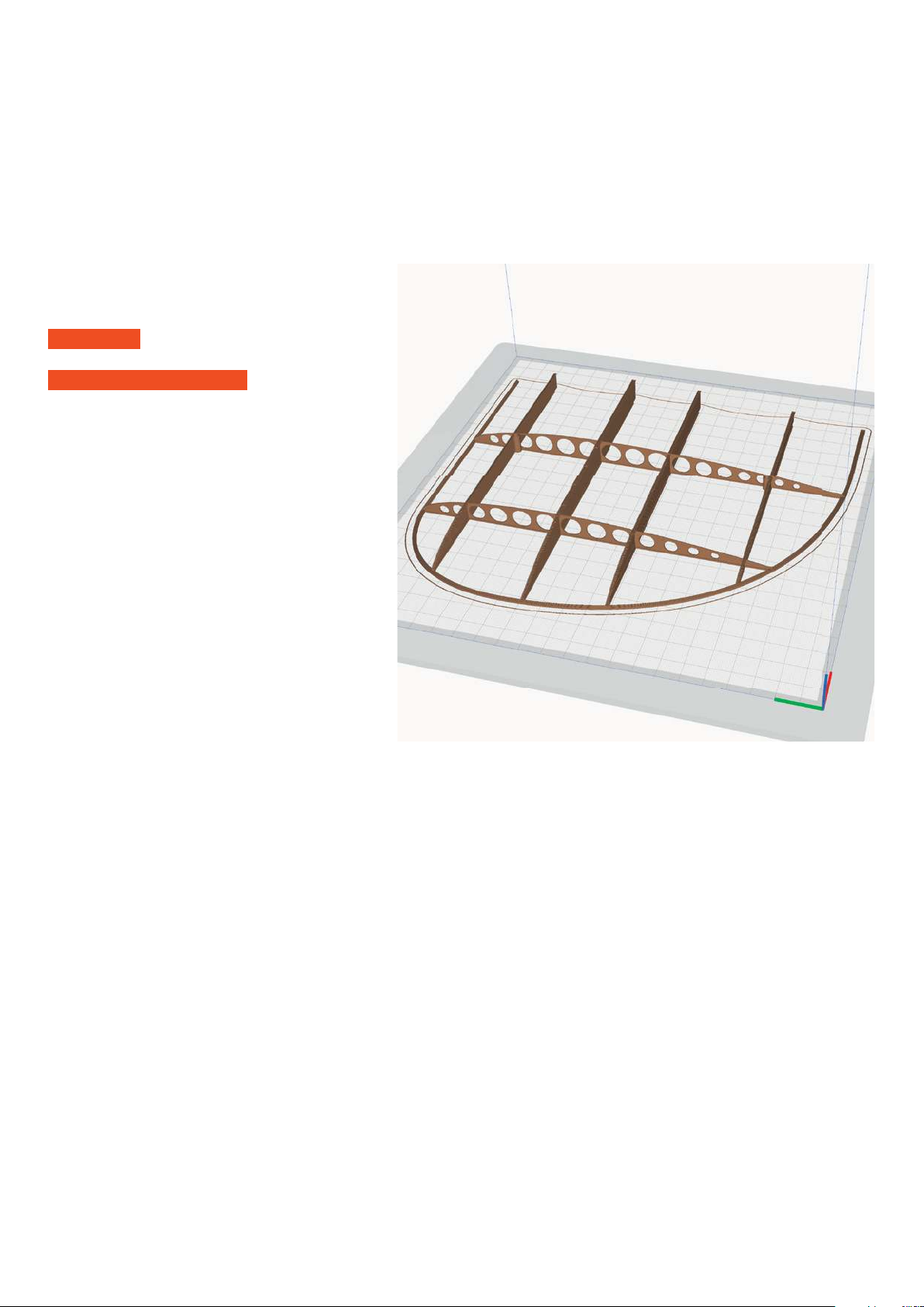
PROFILE P1_Fullbody Tough PLA (or PLA)
The following parts must be sliced with the PROFILE P1_Fullbody.
Please note the additional settings for the individual parts!
P1_Wing 3-L_bl.stl
P1_Wing 3-R_bl.stl
MATERIAL PLA, Weight: ~ 8 g
ADDITIONAL SETTINGS
None required
Page 16
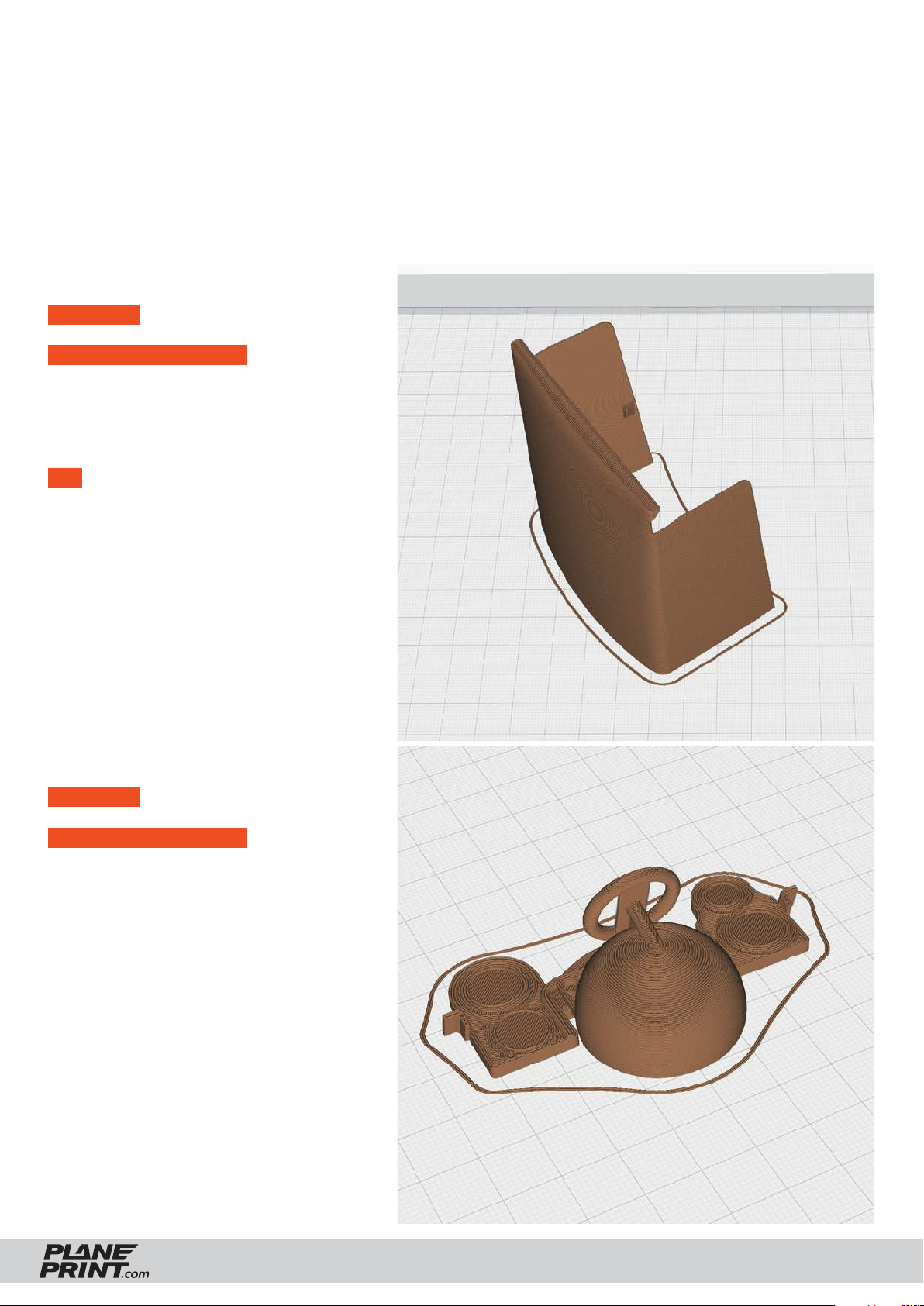
PROFILE P2_Hollowbody
The following parts must be sliced with the PROFILE P2_Hollowbody.
Please note the additional settings for the individual parts!
Tough PLA (or PLA)
P2_Hood_bl.stl
MATERIAL PLA, Weight: ~ 12 g
ADDITIONAL SETTINGS
None required
TIP Paint this part with black acrylic paint
(looks better than black PLA)
P2_Instrument panel_bl.stl
MATERIAL PLA, Weight: ~ 5 g
ADDITIONAL SETTINGS
• Wall Line Count: 1
• Bottom Layers: 1
BLÉRIOT XI
PRINTING & ASSEMBLING MANUAL
© PLANEPRINT
16
Page 17
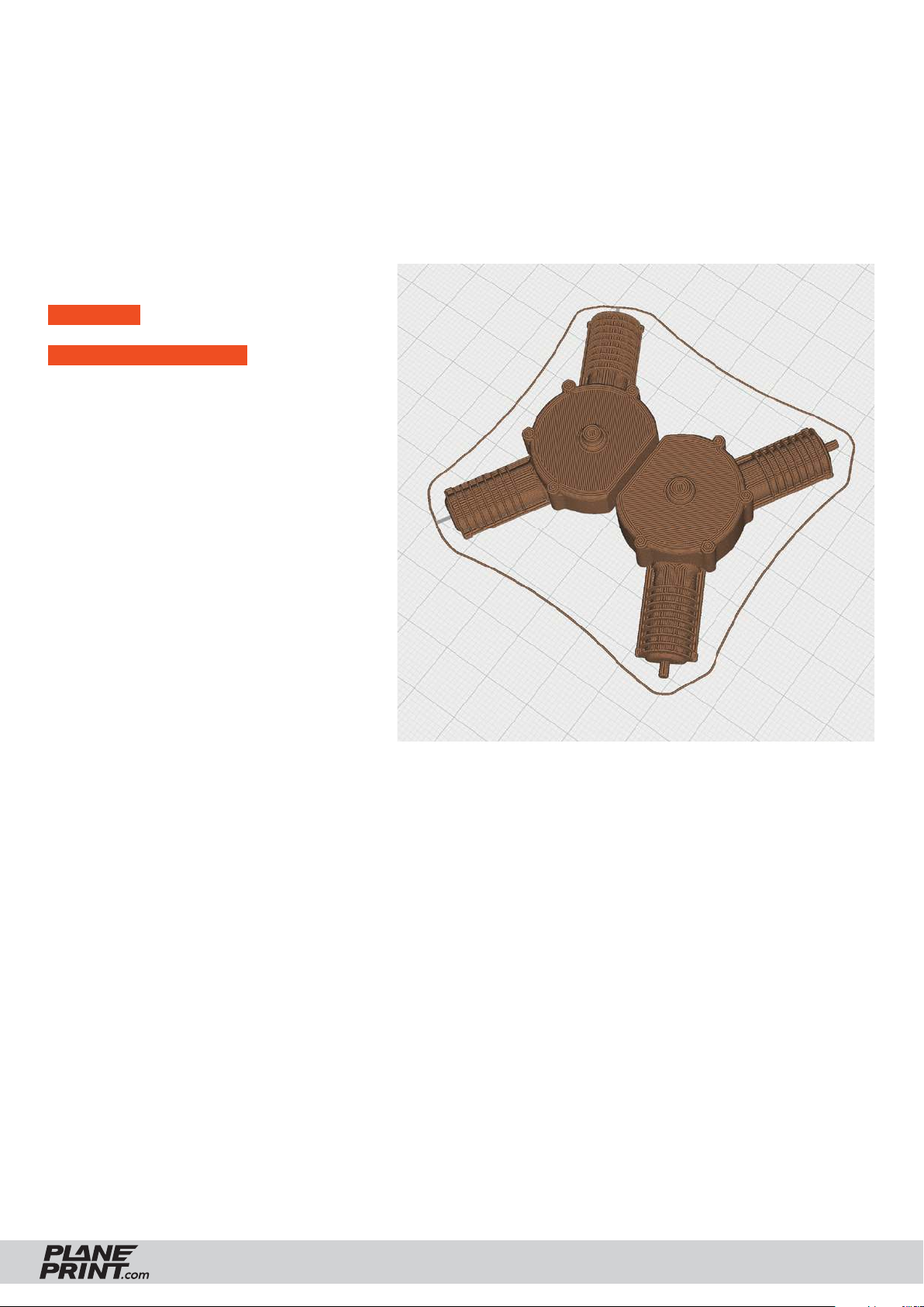
PROFILE P2_Hollowbody
The following parts must be sliced with the PROFILE P2_Hollowbody.
Please note the additional settings for the individual parts!
Tough PLA (or PLA)
P2_Motor_bl.stl
MATERIAL PLA, Weight: ~ 6 g
ADDITIONAL SETTINGS
• Wall Line Count: 1
• Bottom Layers: 0
BLÉRIOT XI
PRINTING & ASSEMBLING MANUAL
© PLANEPRINT
17
Page 18
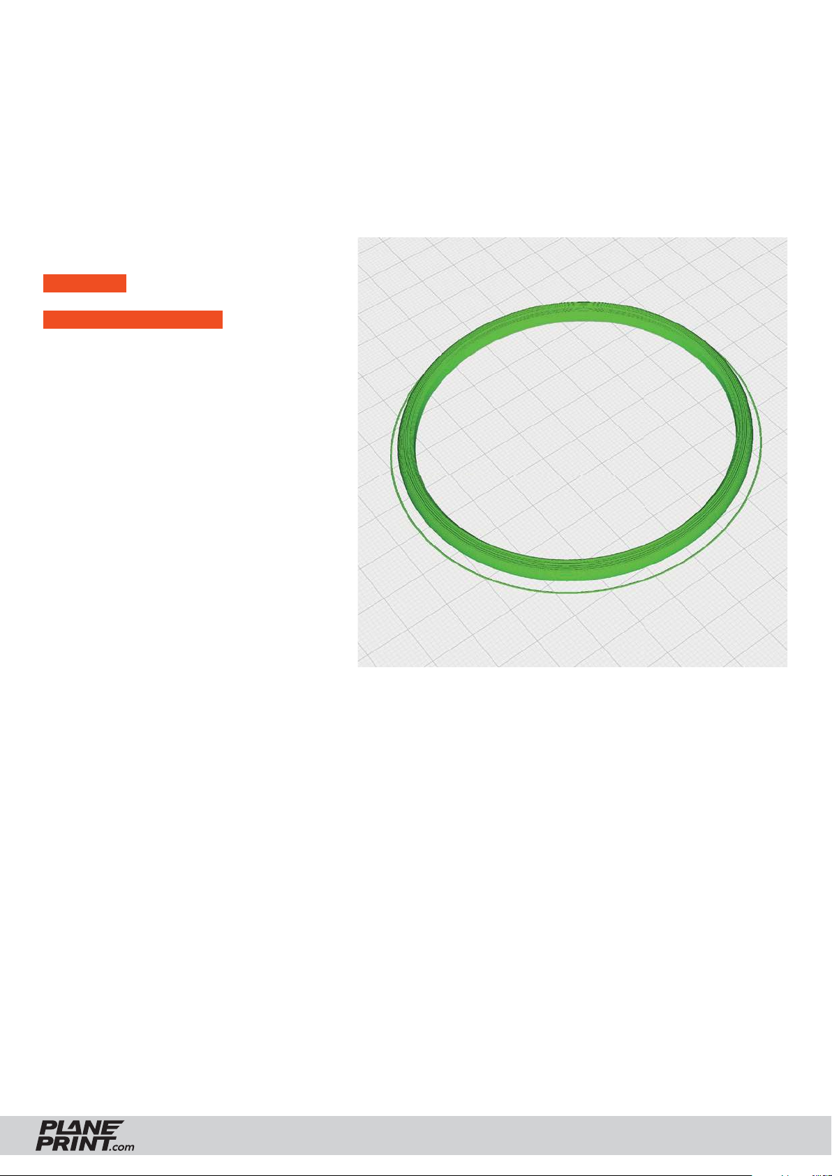
PROFILE P4_Flex
The following parts must be sliced with the PROFILE P4_Flex.
Please note the additional settings for the individual parts!
LW TPU VarioShore
P4_Tire_x2_bl.stl
MATERIAL TPU VarioShore, Weight: ~ 2 g
ADDITIONAL SETTINGS
• Infi ll Density: 100 %
• Flow: 60 % (VarioShore)
• Print it twice
BLÉRIOT XI
PRINTING & ASSEMBLING MANUAL
© PLANEPRINT
18
Page 19
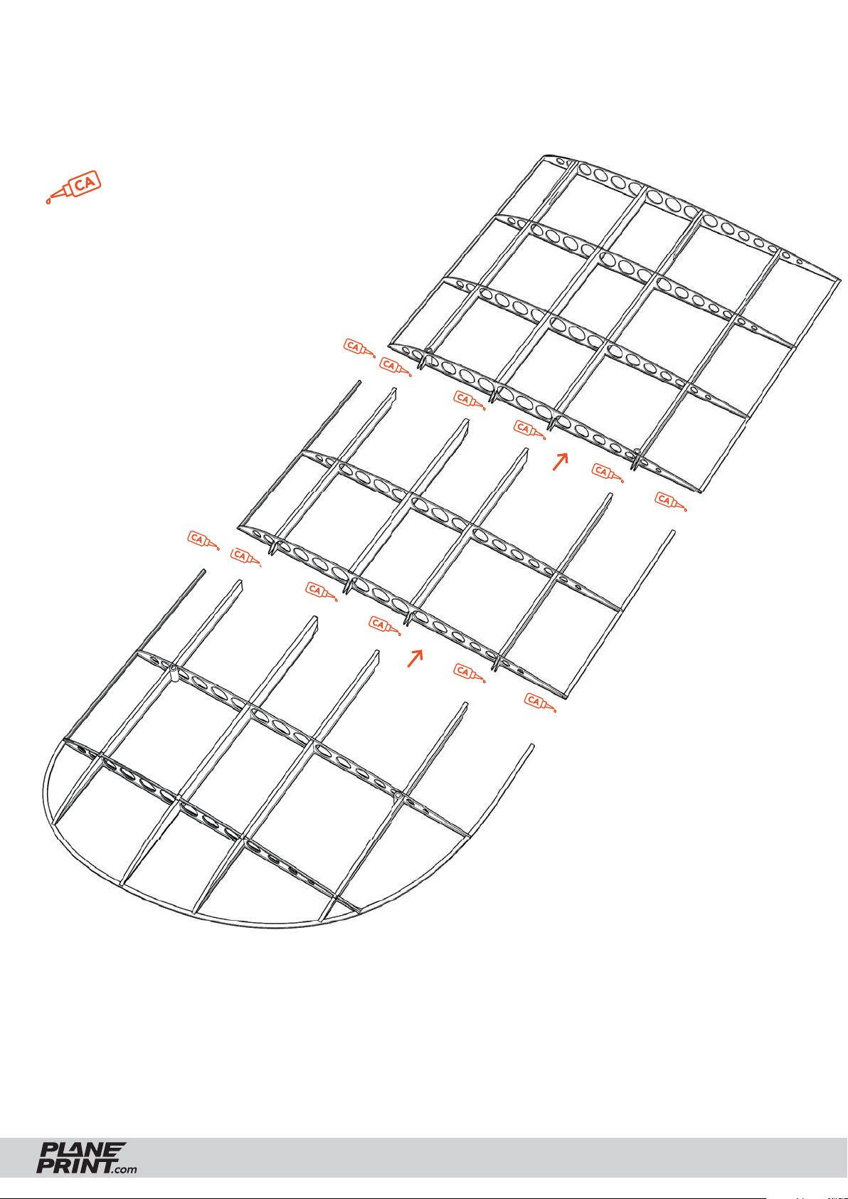
Wings assembly
Mount the wings on a fl at table or surface. Place something to
protect the glued areas, for example the backing paper of an
adhesive fi lm.
medium l.
P1_Wing 1-L_bl.stl
P1_Wing 2-L_bl.stl
P1_Wing 3-L_bl.stl
BLÉRIOT XI
PRINTING & ASSEMBLING MANUAL
© PLANEPRINT
19
Page 20
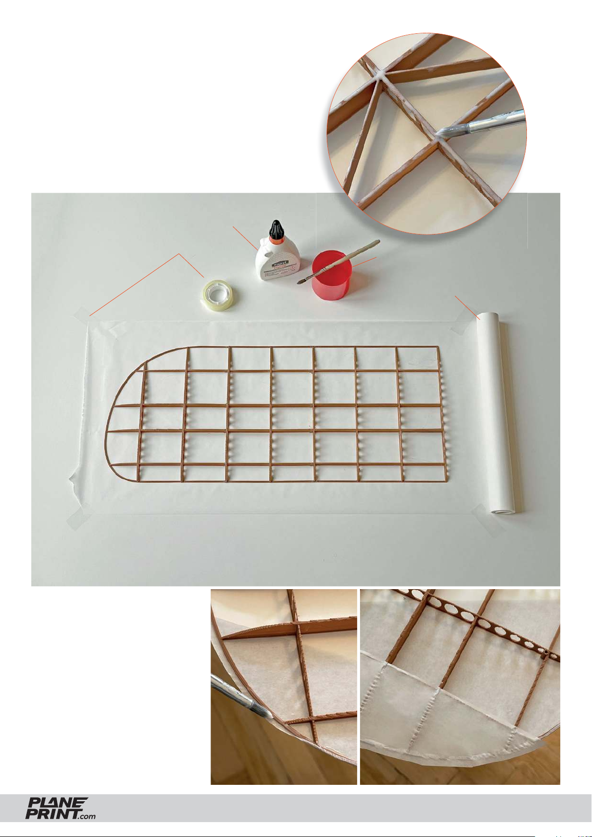
Covering the wings
Tape a piece of Parchment or tissue paper to a fl at surface
without wrinkles.
Dilute the wood glue with a little (little) water and apply it
like paint with a small brush on the underside of the wings.
Place the wing on the paper and weigh it down so that the
entire adhesive surface lies fl at on the paper.
Wood glue
Adhesive tape
Water
Parchment paper
When the glue is dry, cut the paper
with some overhang (5 mm) along
the wing edge and fold it on the
bottom side and glue it with the
help of the brush.
The next step is to glue a strip of
paper to the wingtips, see picture.
Finally, cover the top side.
BLÉRIOT XI
PRINTING & ASSEMBLING MANUAL
© PLANEPRINT
20
Page 21
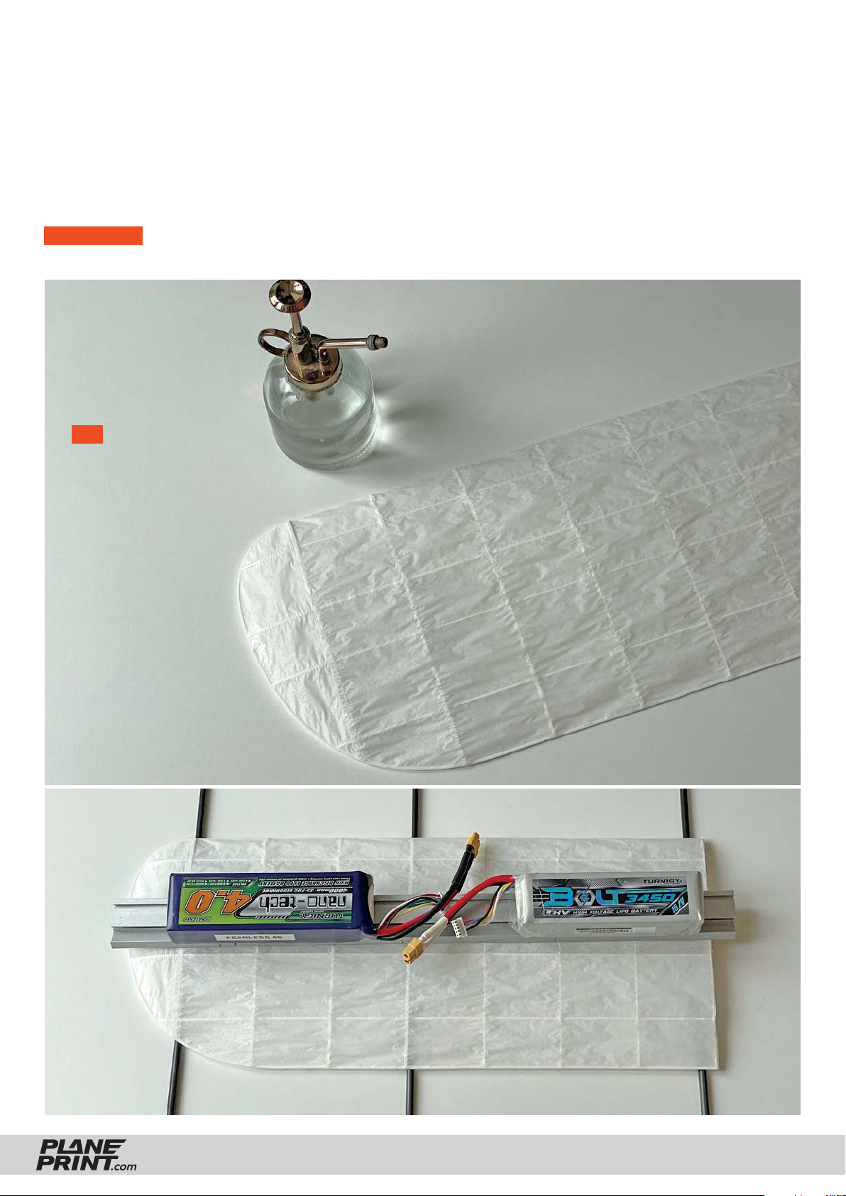
Covering the wings
Now spray the entire wing with a fine water sprayer so that the paper is slightly damp (not wet).
To dry, the wing must lie absolutely flat and be well ventilated at the top and bottom.
Weigh it down at the top in several places so that it cannot warp during drying!
During drying, the paper stretches a little and becomes absolutely smooth. Test this process beforehand
with the paper you are using to be sure (rudder).
IMPORTANT If the wing is twisted after drying, the procedure must be repeated
(It is enough to moisten it only on the top side). The wing must be as flat as possible on the underside.
TIP You can also use
other methods and materials to cover the wings,
there are many tutorials
on youtube.
BLÉRIOT XI
PRINTING & ASSEMBLING MANUAL
© PLANEPRINT
21
Page 22
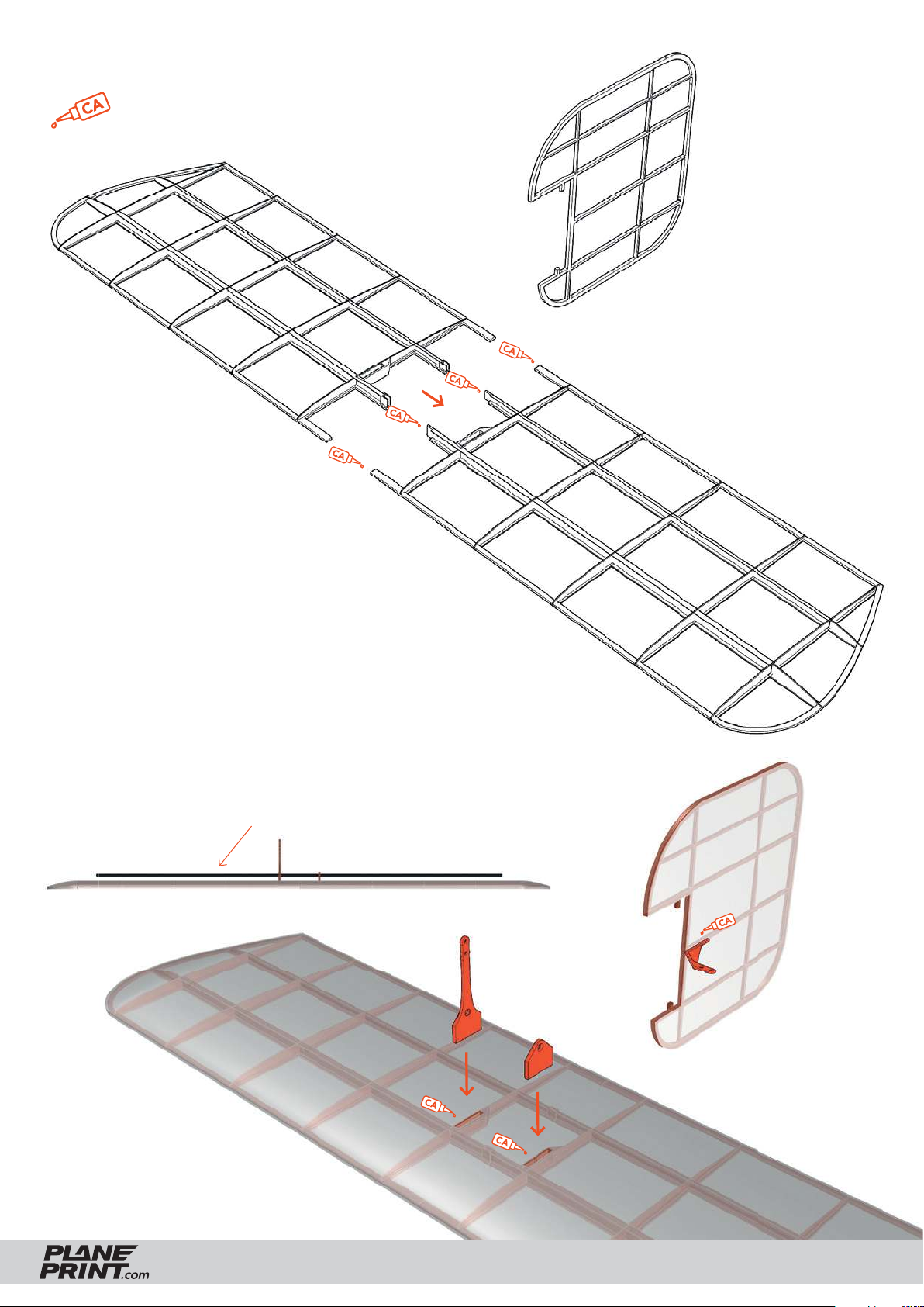
Tailplane assembly
medium l.
P1_Elevator_bl.stl
P1_Rudder_bl.stl
Assemble and cover the elevator and rudder
in the same way as the wings.
Carefully open the slits in the paper with a knife and glue
the control horns in place as shown.
With the help of a 2mm carbon rod, make sure that
the horns are glued in parallel!
P1_Parts_bl.stl
BLÉRIOT XI
PRINTING & ASSEMBLING MANUAL
© PLANEPRINT
22
Page 23
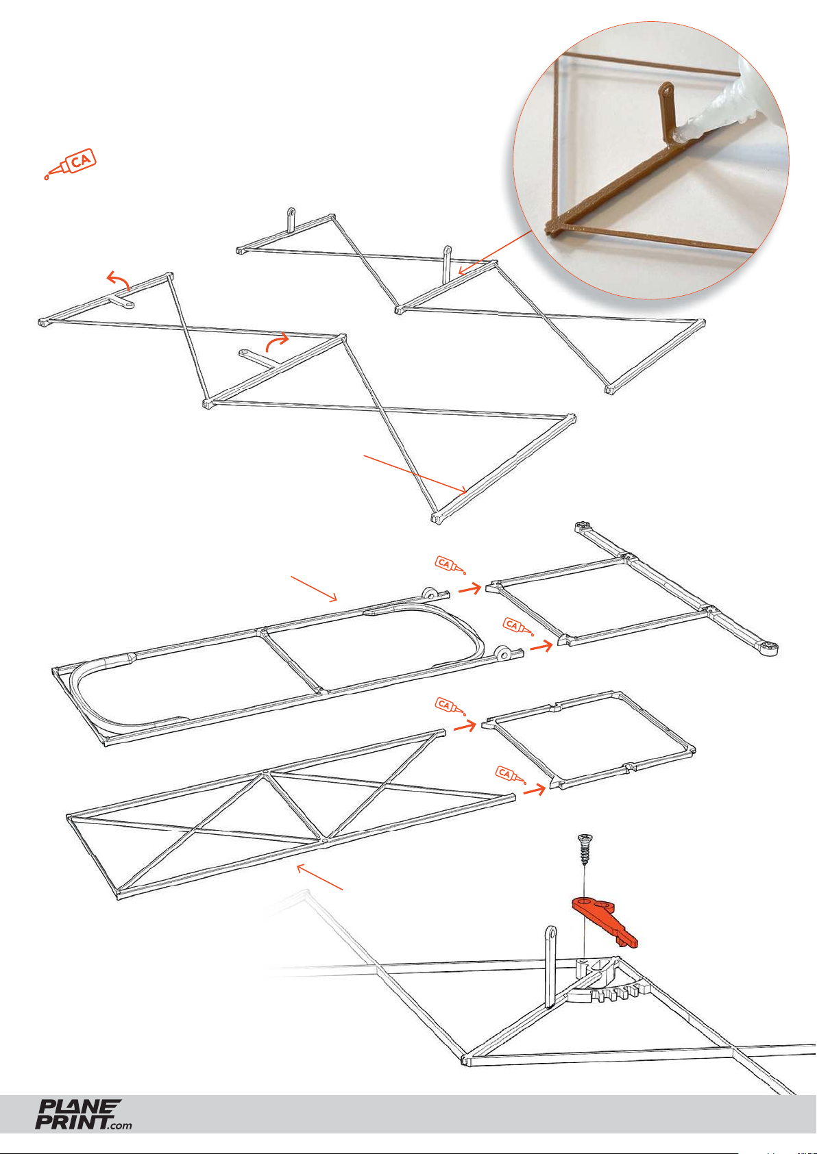
Fuselage assembly
Bend the eyelets for the linkage 90° inwards and fi x
the bending point with a drop of viscous CA glue.
medium or thick l.
P1_Grid 2 side_bl.stl
P1_Grid 3 side_bl.stl
P1_Grid 4 side_x2_bl.stl
Bottom side points upwards
Loosely tighten the lever for
changing the angle of incidence
with a small sheet metal screw so
that the lever can still be moved.
To p
P1_Grid 1_bl.stl
P1_Grid 2_bl.stl
Bottom side
BLÉRIOT XI
P1_Grid 2 side_bl.stl
PRINTING & ASSEMBLING MANUAL
© PLANEPRINT
23
Page 24
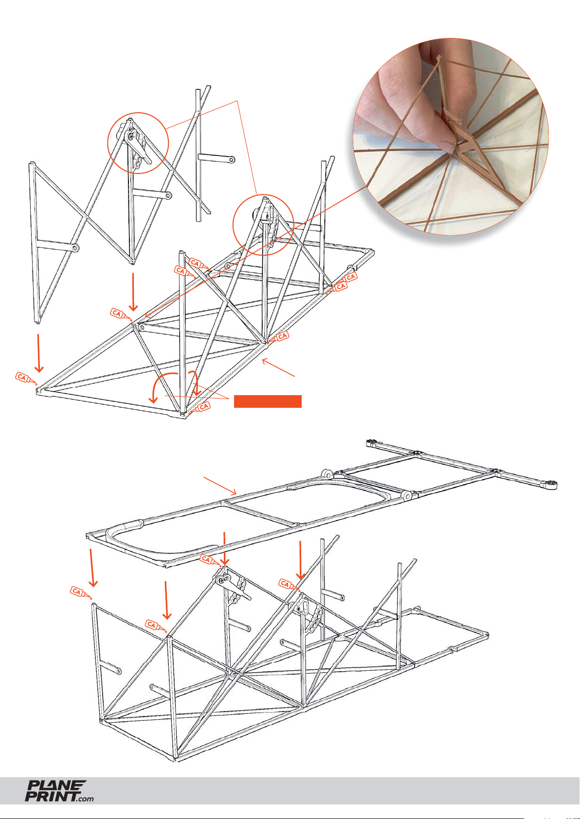
Fuselage assembly
P1_Grid 2 side_bl.stl
Make sure the
alignment is correct!
Use this template (P1_Parts_
bl.stl) to align the parts exactly.
P1_Grid 2_bl.stl
Bottom side
IMPORTANT This angles must be exactly 90°!
To p
BLÉRIOT XI
PRINTING & ASSEMBLING MANUAL
© PLANEPRINT
24
Page 25
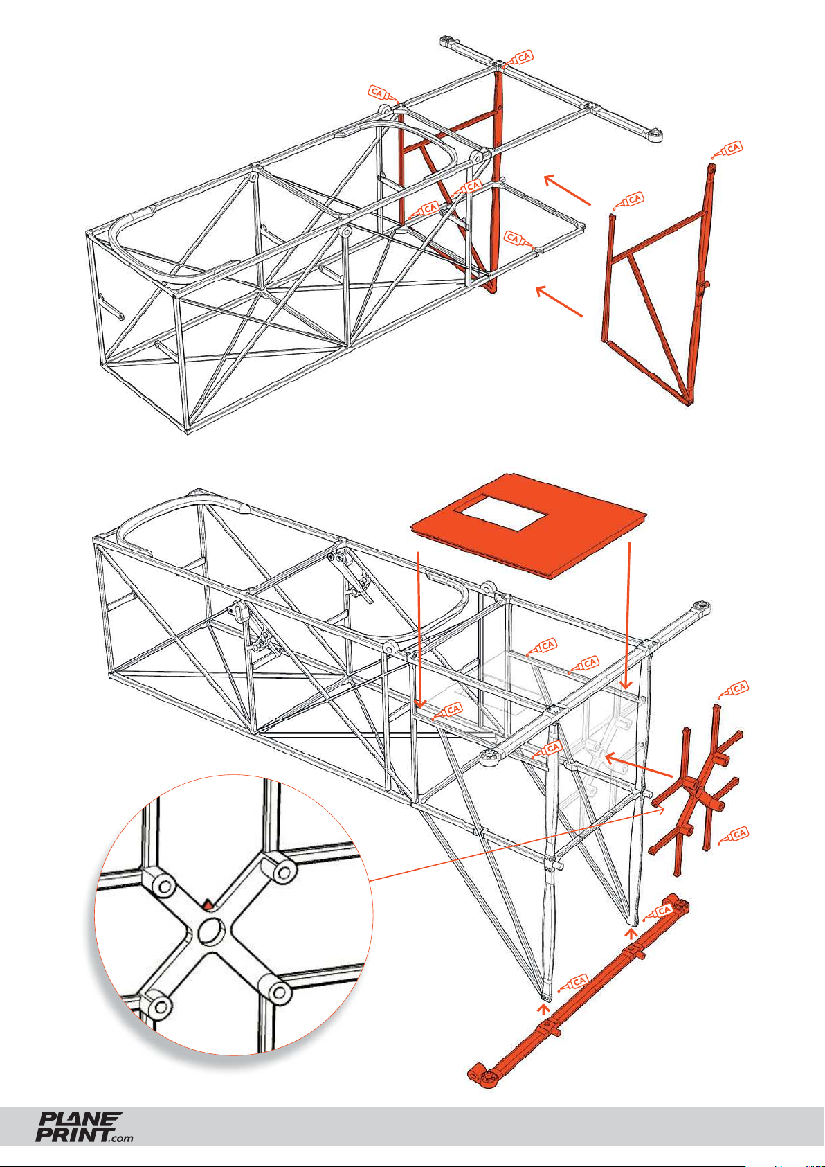
Fuselage assembly
P1_Grid 1 side_bl.stl
This arrow must
point upwards!
P1_Grid 1_bl.stl
BLÉRIOT XI
P1_Grid 1_bl.stl
PRINTING & ASSEMBLING MANUAL
© PLANEPRINT
25
Page 26
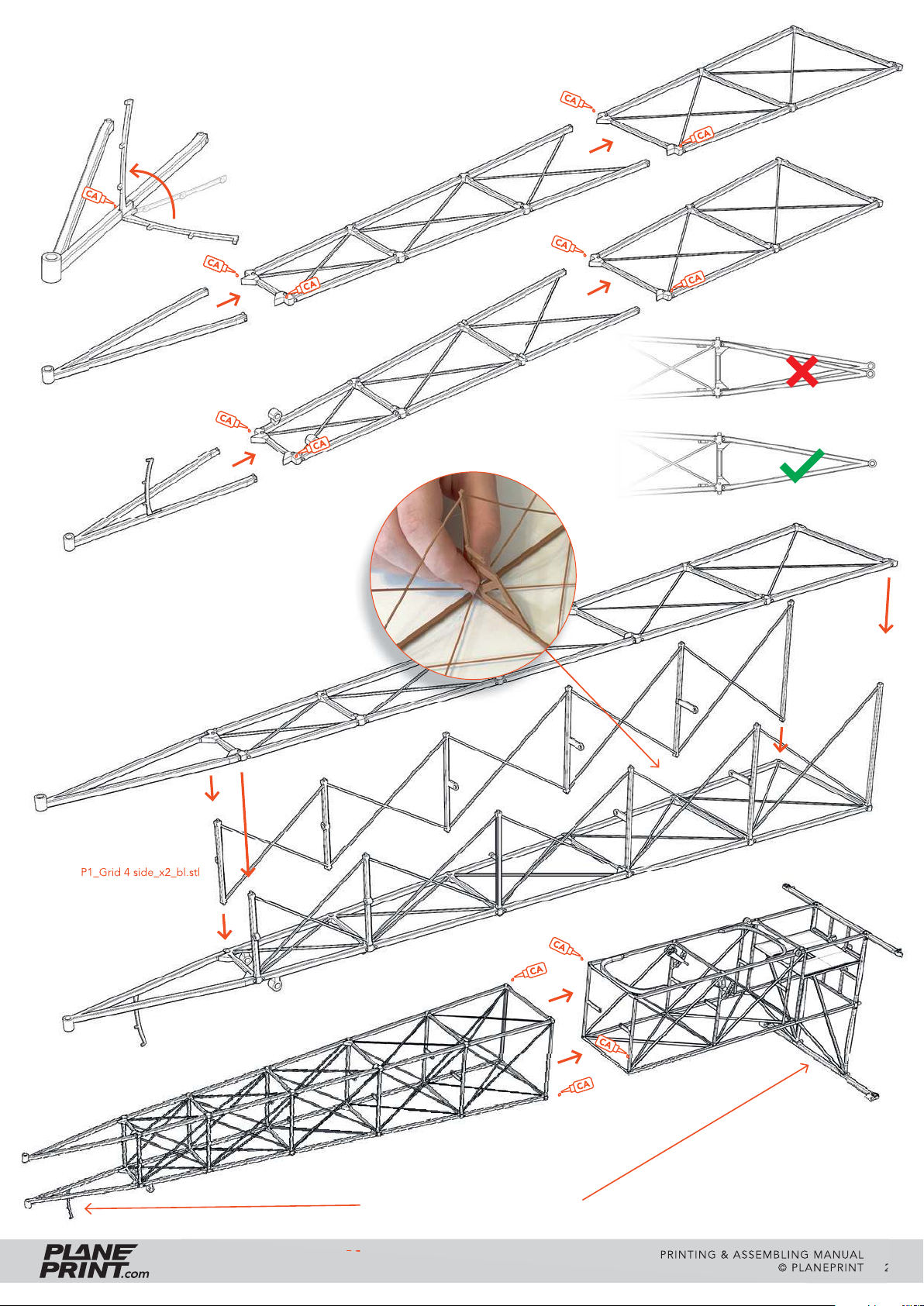
Fuselage assembly
P1_Grid 5_bl.stl
P1_Grid 4 up_bl.stl
P1_Grid 3_bl.stl
P1_Grid 5_bl.stl
Make absolutely sure that the side
parts are exactly at a 90° angle and
that the grid is not twisted!
P1_Grid 4 down_bl.stl
P1_Grid 3 side_bl.stl
P1_Grid 4 side_x2_bl.stl
BLÉRIOT XI
This must point downwards!
PRINTING & ASSEMBLING MANUAL
© PLANEPRINT
26
Page 27
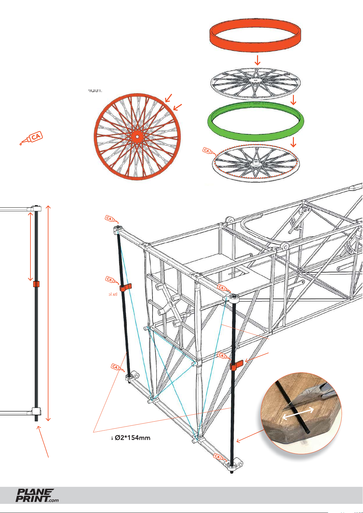
Gear assembly
Apply glue to the lower half of the rim and place it
on a fl at surface. Then place the tire and the upper
rim half on top and press down fi rmly with the help
of the rim template until the glue holds. The spokes
automatically get tension because the inner axle is
higher than the wheel width.
Rotate the rims before
gluing as shown here.
medium or thick l.
P1_Rim template_bl.stl
P4_Tire_x2_bl.stl
P1_Rim_x4_bl.stl
50 mm
P1_Gear_bl.stl
154 mm
thin gray twine
These clips must point
exactly backwards!
Carbon rods Ø2*154mm
The carbon rod must protrude a little at
the bottom to hook in a rubber band!
BLÉRIOT XI
Carbon rod simply roll back and
forth a few times and then break.
PRINTING & ASSEMBLING MANUAL
© PLANEPRINT
27
Page 28
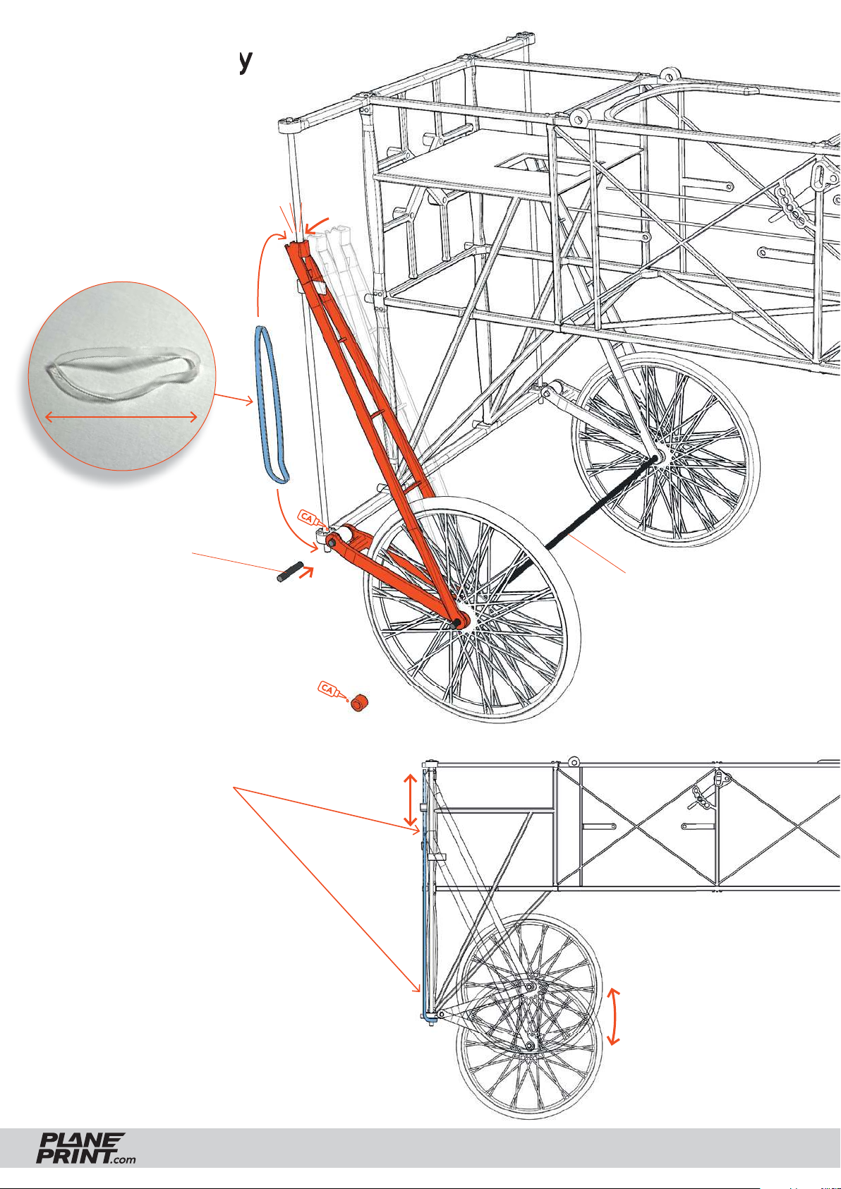
Gear assembly
Hair gum or
rubber band
~ 30 mm
Click!
Carbon rods Ø2*12mm
Make sure that these joints
must be very smooth!
The tension of the rubber
band should be just strong
enough so that the gear does
not sink in by itself. If the
gear is very softly sprung, the
landings will be super soft
and like original.
Carbon rod Ø2*175mm
P1_Gear_bl.stl
BLÉRIOT XI
PRINTING & ASSEMBLING MANUAL
© PLANEPRINT
28
Page 29
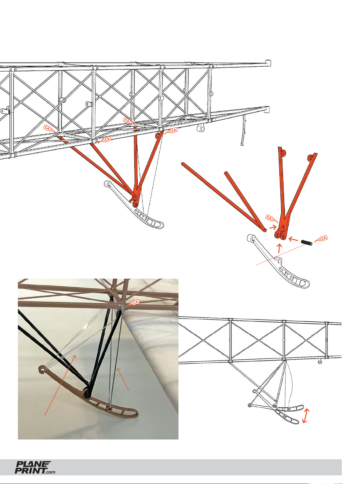
Spring loaded tail spur
Adjust the twine so that the tail spur
points approximately 45 down.
Carbon rod Ø2*10mm
thin gray twine
Hair gum or rubber band
BLÉRIOT XI
PRINTING & ASSEMBLING MANUAL
© PLANEPRINT
29
Page 30
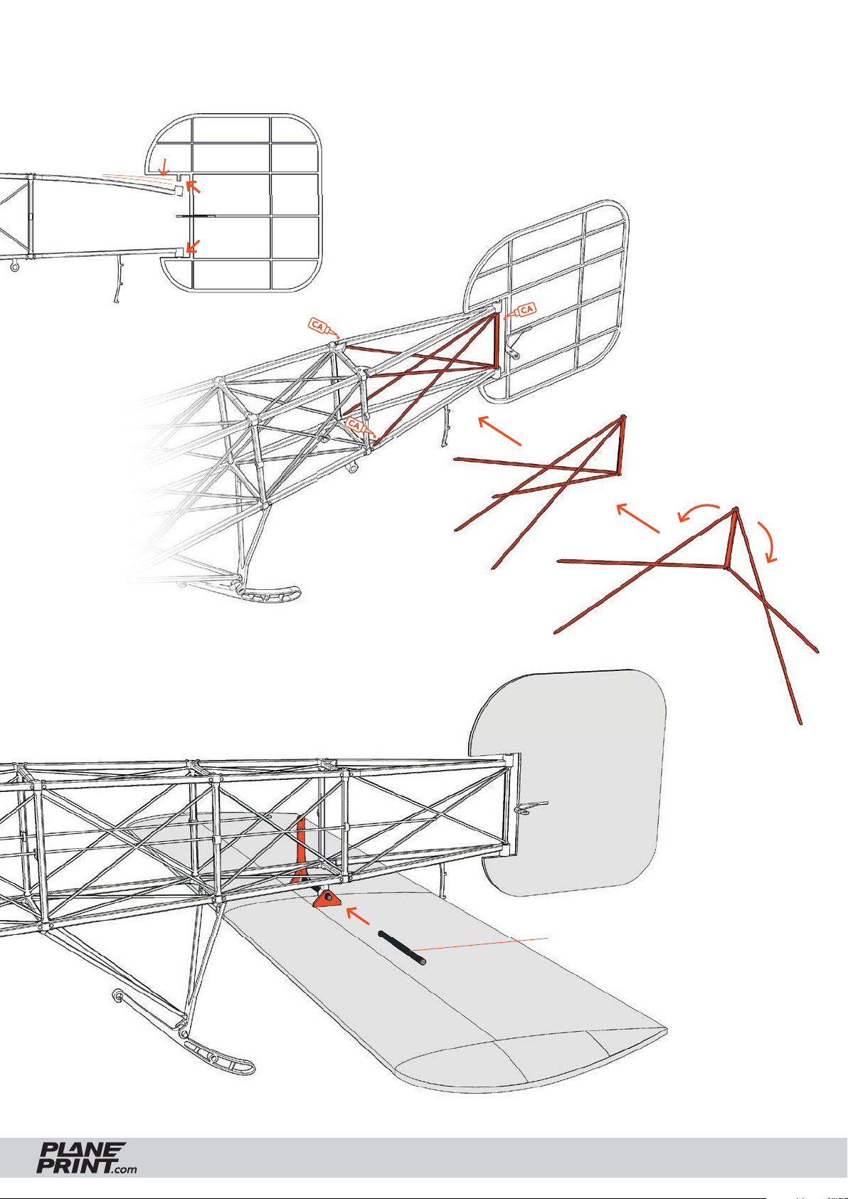
Tail plane assembly
The rudder must be easy to move.
Fix the carbon rod on the outside with a drop
of glue. No glue may get into the joint!
P1_Grid 5_bl.stl
Carbon rod Ø2*40mm
BLÉRIOT XI
PRINTING & ASSEMBLING MANUAL
© PLANEPRINT
30
Page 31
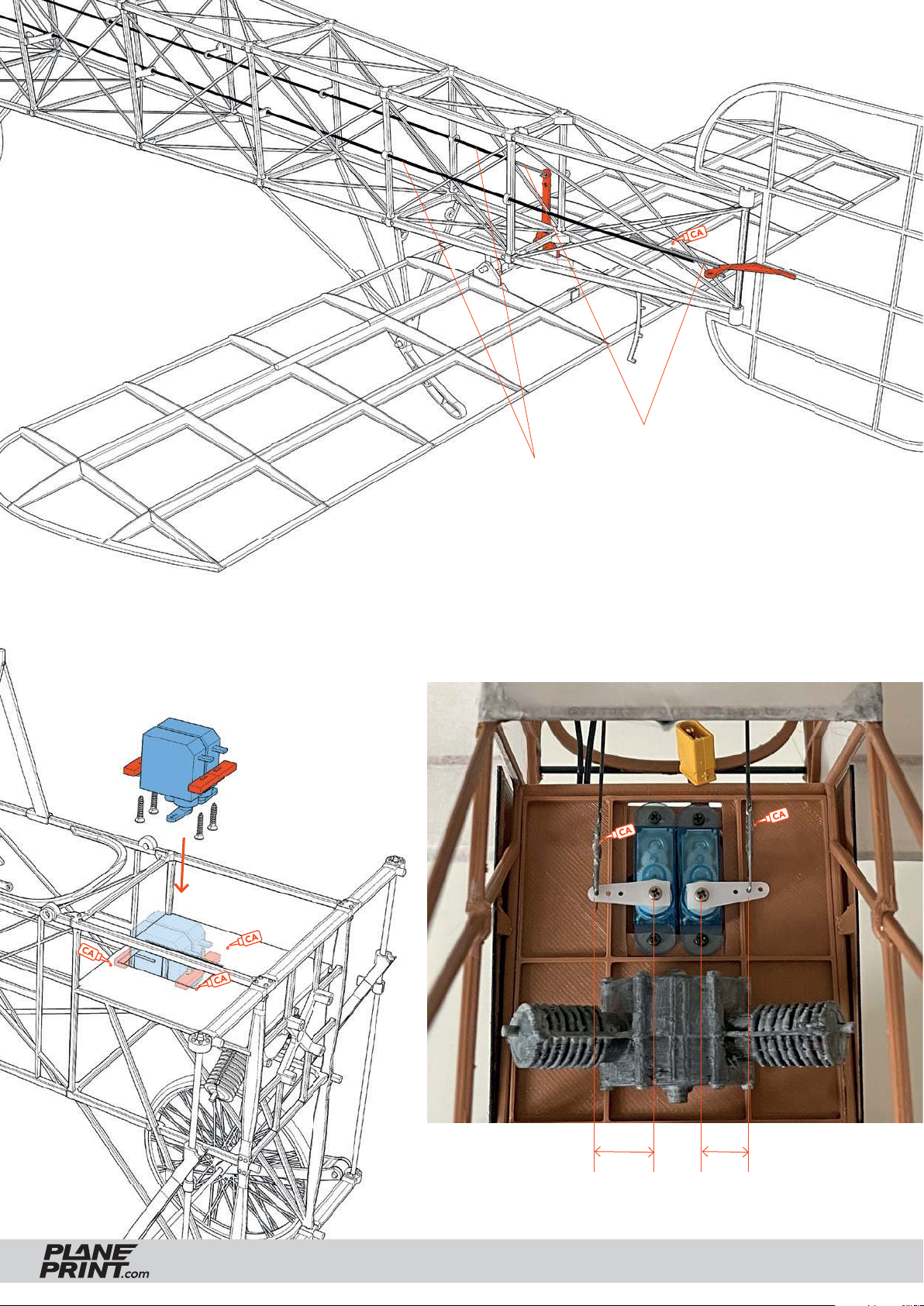
Servo mount
Steel wire Ø0.8mm
Carbon rod Ø0.8mm
Thread the carbon rods through the eyelets of the fuselage
and glue the steel wires with CA glue in the correct position
(servo and rudder/elevator in zero position).
P1_Parts_bl.stl
10 mm 8 mm
Rudder Elevator
BLÉRIOT XI
PRINTING & ASSEMBLING MANUAL
© PLANEPRINT
31
Page 32
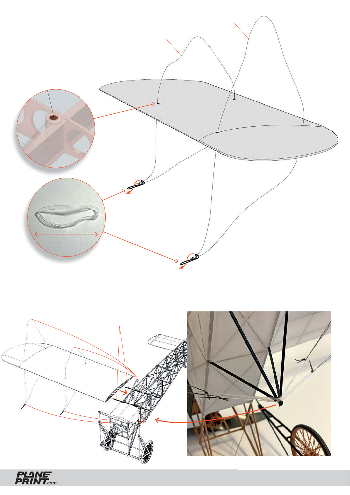
Wing ropes
Carefully open the holes
in the paper and thread
the twine through the
wing from above.
Hair gum or
rubber band
grey twine 160 mm
grey twine 100 mm
~ 30 mm
Attach the wings to the fuselage as shown in the picture, hang the wing ropes on the top and then on the
bottom. The ropes should NOT be glued to the wing!
Carbon rods Ø2*142mm
BLÉRIOT XI
PRINTING & ASSEMBLING MANUAL
© PLANEPRINT
32
Page 33
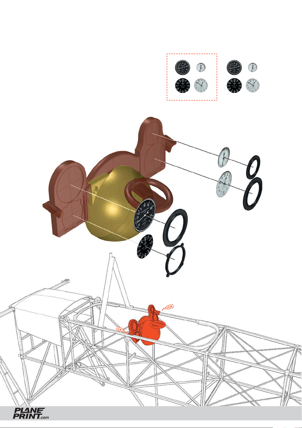
Instrument panel assembly
Print this page (format 100 %!) and cut out the
instruments on the right.
Then glue them behind the frames as shown in the picture.
The spherical tank should be painted in brass or gold.
BLÉRIOT XI
Then glue the instrument panel here.
PRINTING & ASSEMBLING MANUAL
© PLANEPRINT
33
Page 34
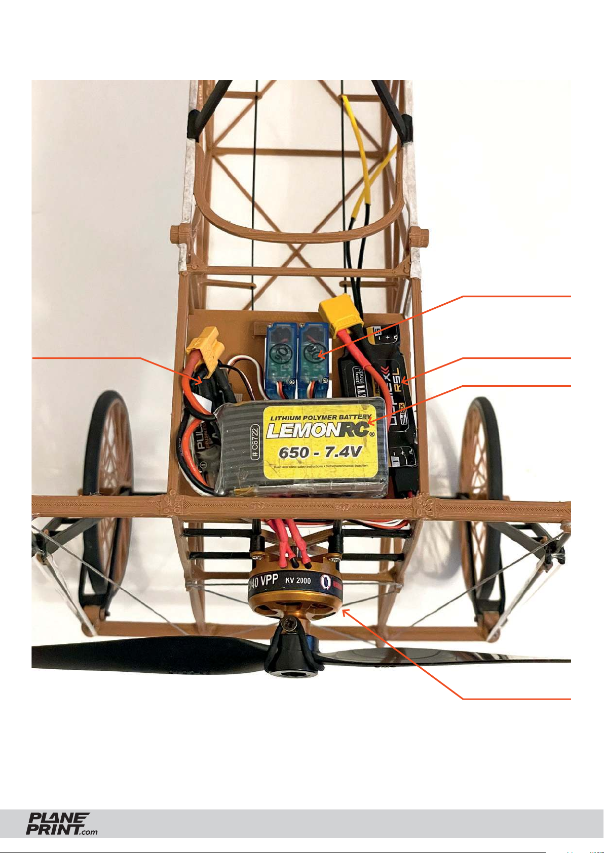
RC components
Servos
Controller
Receiver
Battery
BLÉRIOT XI
Motor
PRINTING & ASSEMBLING MANUAL
© PLANEPRINT
34
Page 35
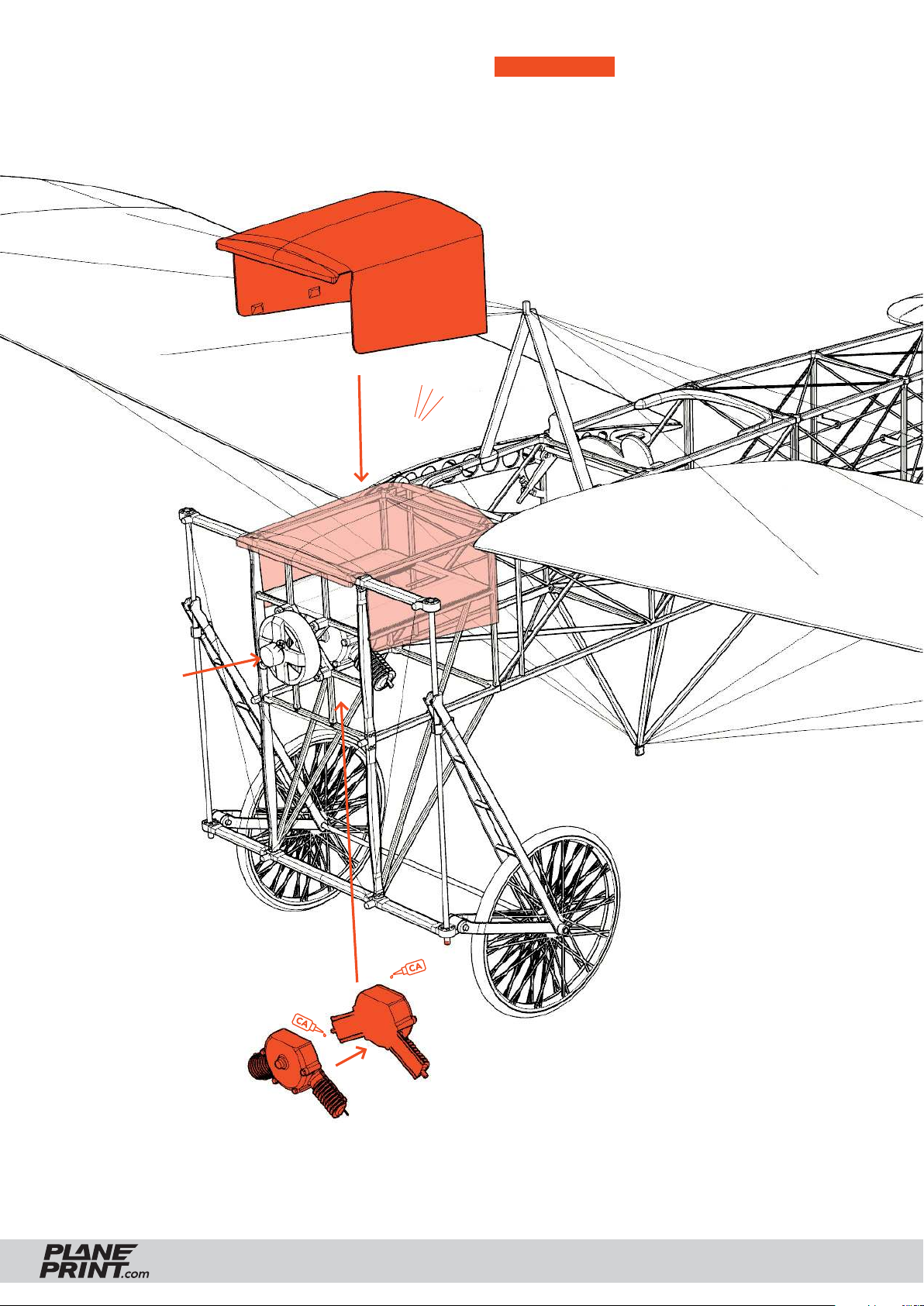
Motor and hood
SAFETY FIRST Use appropriate screws for
motor mounting to ensure safe operation!
Make sure the prop runs smoothly and does
not generate vibrations. Check regularly that
the motor mounting is absolutely tight!
P2_Hood_bl.stl
Click!
Screw the motor
tight here.
On page 31 you can see a
photo of the motorized dummy.
P2_Motor_bl.stl
BLÉRIOT XI
PRINTING & ASSEMBLING MANUAL
© PLANEPRINT
35
Page 36
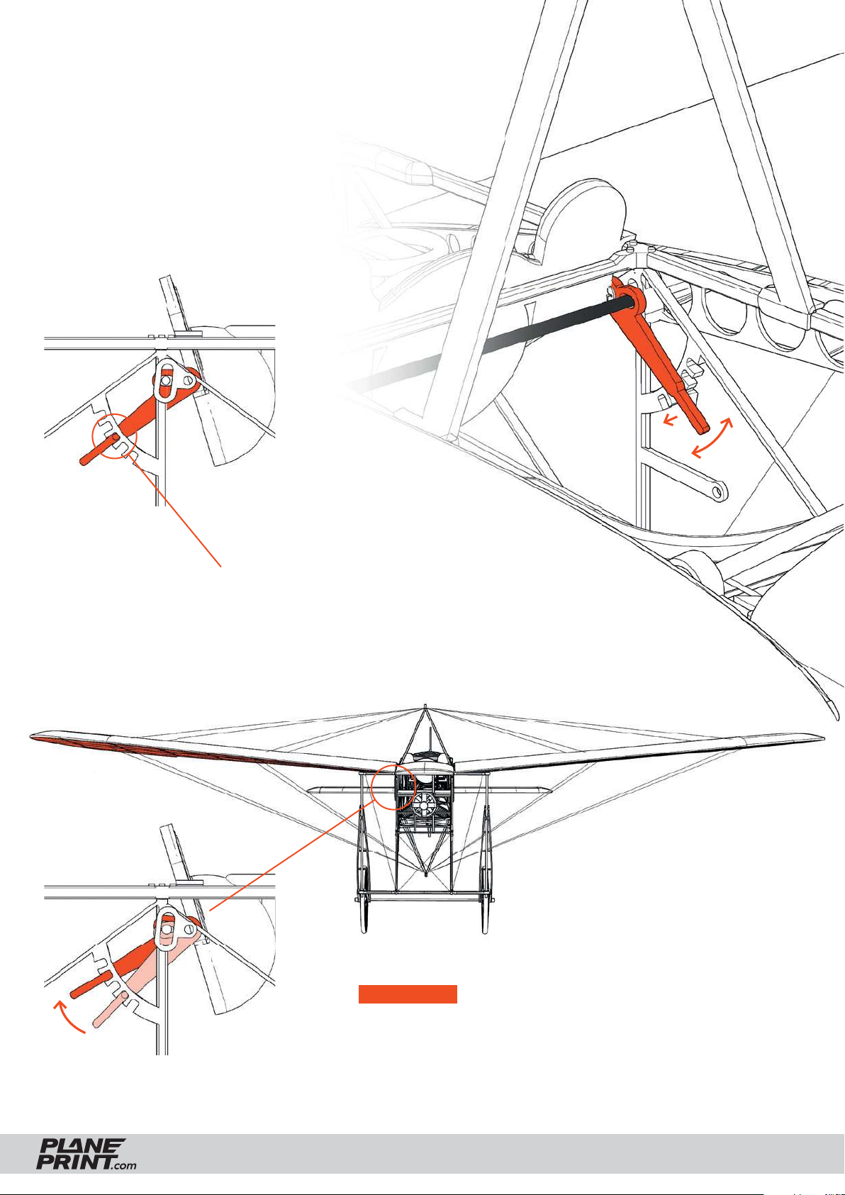
Wing adjustment and AOI
Since it is diffi cult to string the wings
absolutely fl at, there is the possibility to adjust the Angle of Incidence
(AOI) for both wings separately. No
tools are necessary and you can adjust the angle at any time.
The correct AOI is in the middle setting.
If a wing is slightly twisted, change the angle by
one notch. If it is not enough, change the other
wing in the opposite direction.
IMPORTANT Due to changes in temperature and
humidity, check before fl ight that the wings are as
parallel as possible by looking from exactly in front or
behind, otherwise correct it with the AOI levers.
BLÉRIOT XI
PRINTING & ASSEMBLING MANUAL
© PLANEPRINT
36
Page 37
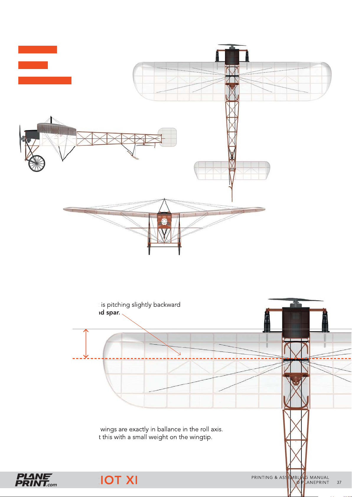
Technical specifi cations
WINGSPAN 1016 mm/40 inches
LENGTH 800 mm/31 inches
FLIGHT WEIGHT 285 grams
Center of Gravity (CG)
The CG fi ts when the aircraft is pitching slightly backward
when balanced on the second spar.
75 mm
Do not forget to check if the wings are exactly in ballance in the roll axis.
If one wing is heavier, correct this with a small weight on the wingtip.
BLÉRIOT XI
PRINTING & ASSEMBLING MANUAL
© PLANEPRINT
37
Page 38
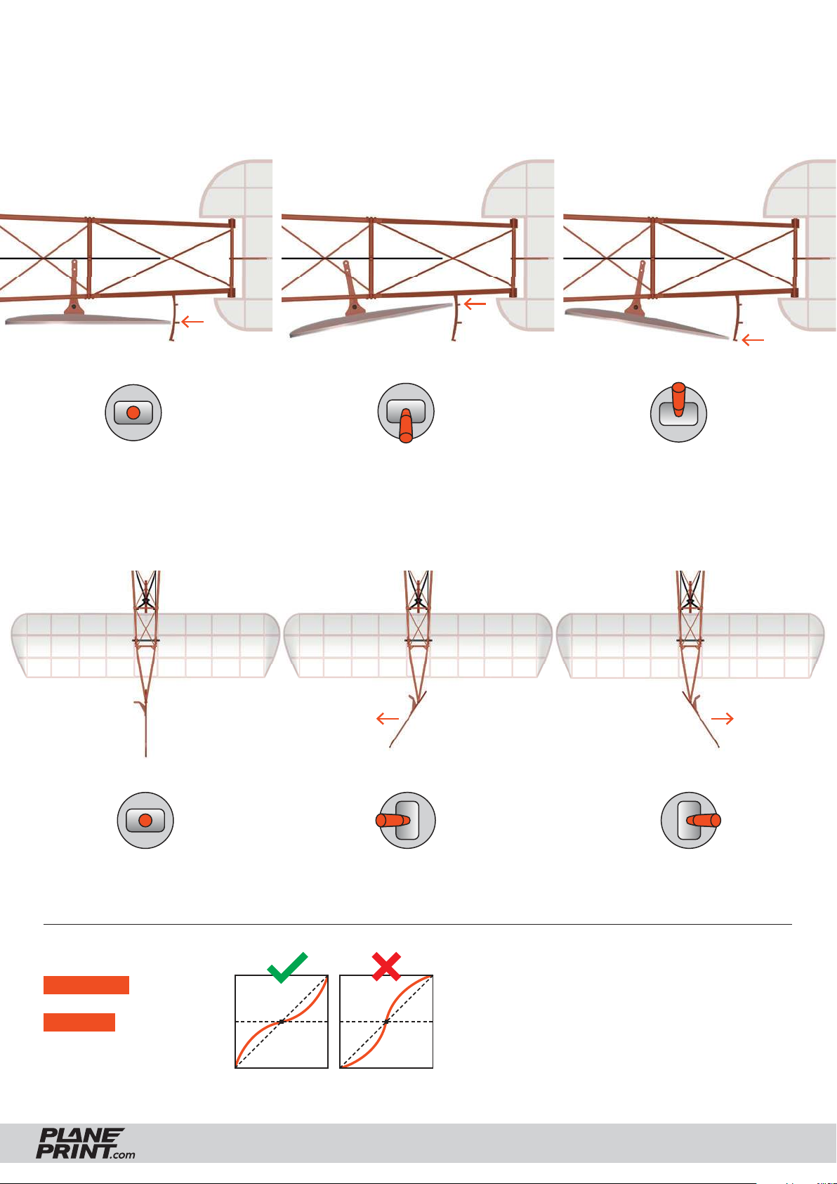
Settings for fl ying
When checking the control directions, look at the elevator from left.
Elevator neutral
When checking the control directions, look at the rudder from above.
about 35° about 35°
Elevator up
Elevator down
Rudder neutral
Expo setting
ELEVATOR 30 %
RUDDER 30 %
BLÉRIOT XI
Rudder left
(for some remote
controls a minus
has to be in front
of the number)
Rudder right
PRINTING & ASSEMBLING MANUAL
© PLANEPRINT
38
Page 39

AGE RECOMMENDATION 14+
NOT FOR CHILDREN UNDER 14 YEARS.
THIS IS NOT A TOY!
The STL data (or data processed from it, such as G codes)
must never be passed on to third parties!
The purchase of the STL does not authorize the production
of models for third parties.
By using the download data, an RC model airplane, called
„model“ for short, can be manufactured using a 3D printer.
As a user of this model, only you are responsible for safe
operation that does not endanger you or others, or that
does not damage the model or property of others.
PLANEPRINT.com assumes no responsibility for damage to
persons and property caused by pressure, transport or use
of the product. Filaments, printing supplies, hardware or
consumables that can not be used after faulty 3D printing
will not be replaced by PLANEPRINT.com in any way.
When operating, always keep a safe distance from your
model in all directions to avoid collisions and injuries.
This model is controlled by a radio signal. Radio signals can
be disturbed from outside without being able to influence
it. Interference can lead to a temporary loss of control.
Always operate your model on open terrains, far from cars,
traffic and people.
Keep all chemicals, small parts and electrical components
out of the reach of children.
Avoid water contact with all components that are not specially
designed and protected. Moisture damages the electronics.
Never take an item of the model or accessory in your mouth
as this can lead to severe injuries or even death.
Never operate your model with low batteries in the transmitter or model.
Always keep the model in view and under control.
Use only fully charged batteries.
Always keep the transmitter switched on when the model
is switched on.
Always remove the battery before disassembling the model.
Keep moving parts clean and dry at all times.
Always allow the parts to cool before touching them.
Always remove the battery after use.
Make sure that the Failsafe is properly set before the flight.
Always follow the instructions and warnings for this product
and any optional accessories (servos, receivers, motors,
propellers, chargers, rechargeable batteries, etc.) carefully.
We develop our models to the best of our knowledge and belief.
We accept no liability for consequential damage and injuries
caused by improper use or incorrectly printed parts. Please be
careful when handling motors, batteries and propellers and
only move your model with insurance and in approved places!
Never operate the model with damaged wiring.
Never touch moving parts.
© PLANEPRINT.com, A-6021 Innsbruck, Conradstraße 6, [email protected]
© Design STL files by René Marschall • Layout: marschall designlab, marschall.cc
 Loading...