

Page 1
8
FAA PMA
5700
YWWSN
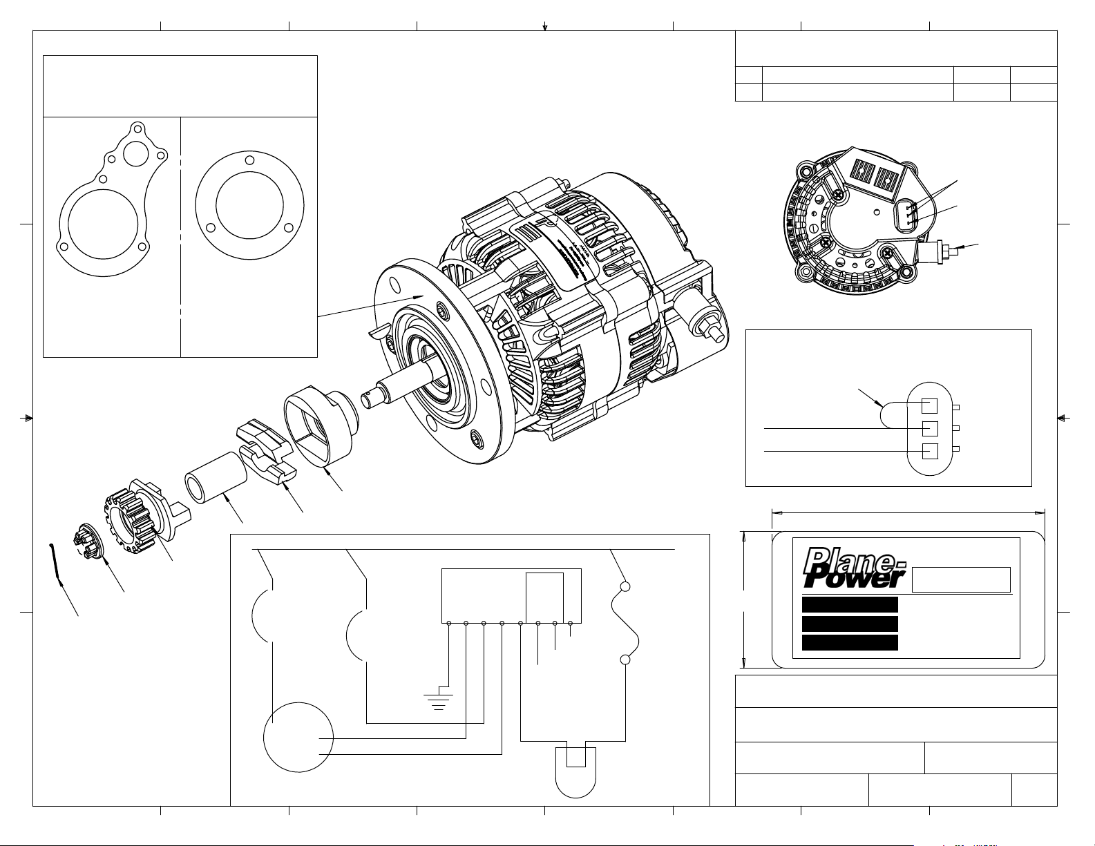
4 VOLT 50 AMP GEAR DRIVEN ALTERNATOR
1
67
NOTE: BOTH GASKETS SUPPLIED
USE APPROPRIATE GASKET FOR
YOUR ENGINE
D
NOTE: PARTS MARKED WITH * ARE
HOWN FOR INSTALLATION PURPOSES
S
ONLY AND ARE NOT SUPPLIED WITH KIT,
AVAILABLE SEPERATELY - GEAR ASSEMBLY ER14-GR
5
4
3
12
REVISIONS
TR.
L
UPDATED INSTRUCTIONS
A
DESCRIPTION
DATE
9/2/08
FIELD
AUX
6mm
OUTPUT (B+)
TERMINAL
APR.
SJK
D
GASKET
C
TCM P/N 35019
S
UPERIOR AIRPARTS
SA35019
B
*
A
GASKET
TCM P/N 649984
or
SUPERIOR AIRPARTS
or
SA352066
PRE-WIRED FIELD PLUG WIRING DIAGRAM
AS VIEWED FROM REAR OF CONNECTOR
JUMPER 20 GA.
C
3
20 GA. (RED)
20 GA. (WHITE)
FIELD
A
UX
2
1
*
*
*
WIRE MUST CONFORM TO MIL-W-22759/16
AIRCRAFT BUS
*
*
8
7
*ALTERNATOR
CIRCUIT
BREAKER
0 AMP
5
MAXIMUM
8 GA. MIN
OUTPUT
(B+)
AL
TERNATOR
*FIELD
CIRCUIT
BREAKER/
SWITCH
5 AMP
20 GA. MIN
20 GA. MIN (RED)
FIELD
20 GA. MIN (WHITE)
AUX
WIRING DIAGRAM
NOTE: ANY NEW OR REPLACEMENT
R1224B REGULATOR
ENABLE
GRND
FLD
20 GA. MIN
AUX
DUAL
A
LTERNATOR
ONLY
LAMPINOUT
N/C
N/C
N/C
N/C
*INDICATOR
FUSE, OR
CIRCUIT
BREAKER
1 AMP
24 GA. MIN
ALTERNATOR
INOPERATIVE
LAMP
* NOT SUPPLIED
456
PLANE POWER, LTD.
For eligibility see
www.plane-power.com/catalog
or call
.75"
MODEL NO.
SERIAL NO.
VOLTAGE
PLANE POWER, LTD.
G
ER14-50 INSTALLATION INSTRUCTIONS
DRAWN BY:
MATERIALS:
3
1.87"
ER14-50
ER14-
14
RANBURY, TEXAS
DWG. NO.
11-1001A
2
B
1-877-934-
A
DATE:
8/10/07B. JOWERS
REV.
A
1
Page 2

Plane Power, Ltd. Dwg. 11-1001 Created 8-10-2007 Rev. A Page 2 of 4
ER14-50 INSTALLATION INSTRUCTIONS
READ AND THOROUGHLY UNDERSTAND ALL OF THE INSTALLATION
INSTRUCTIONS BEFORE BEGINNING INSTALLATION OF THIS KIT.
NOTE: IF AIRCRAFT DOES NOT HAVE A CIRCUIT BREAKER OR CURRENT LIMITING
DEVICE IN THE GENERATOR OUTPUT WIRE AND REGULATOR INPUT TERMINAL PER
AC43.13-1B SECTION 4, DO NOT INSTALL THIS KIT. ANY NEW OR REPLACEMENT WIRE
MUST CONFORM TO MIL-W-22759/16.
Disconnect aircraft battery “–“ terminal (ground). Consult AC43.13-1B Chapter 11 Section 2, 11-22, E for additional
1.
information.
2. Remove existing voltage regulator by removing wiring and three mounting bolts. Remove existing generator by
removing wiring and three nuts and washers. Remove mounting gasket and inspect mounting surface and mounting
studs for any abnormalities. Correct all issues before installing ER14-50 Alternator Kit. Consult engine or airframe
maintenance manual for further instructions if required.
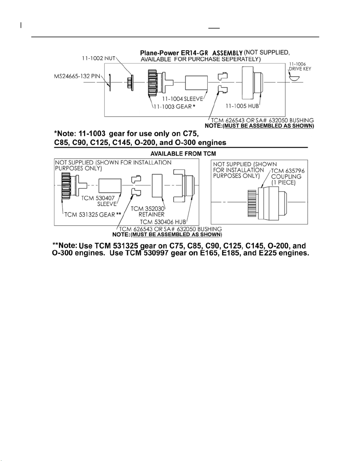
3. Remove drive gear assembly from old generator. If assembly is in airworthy condition and all part numbers match the
TCM part numbers on Figure A page 4 of this manual the drive gear assembly may be re-used. Otherwise purchase a
new Plane-Power gear assembly P/N ER14-GR or a TCM gear assembly. (See Fig. A, Page 4)
4. If original gear assembly is to be re-used inspect gear, sleeve, retainer and hub for airworthy condition. Replace any
worn/damaged parts or assemblies. Old bushings, TCM Part Number 626543 or SA # 632050, must be replaced
with new.
NOTE: IT IS THE RESPONSIBILITY OF THE INSTALLER TO THOROUGHLY INSPECT AND PROPERLY
INSTALL THE GEAR ASSEMBLY. DAMAGE TO THE ALTERNATOR FROM THE INSTALLATION OF WORN,
DEFECTIVE OR IMPROPERLY INSTALLED PARTS WILL VOID ER14-50 WARRANTY AND MAY CAUSE
ENGINE DAMAGE.
------------------(Refer to Pages 1 and 4)------------------
5. ASSEMBLE DRIVE GEAR ASSEMBLY WITH 2 NEW BUSHINGS TCM P/N 626543 OR SA# 632050
alternator shaft. Ensure Bushings and Drive Key are properly installed in shaft.
6. Torque Shaft Nut Plane-Power # 11-1002 or TCM P/N 530412 to Minimum torque of 180 inch Lbs. and install cotter pin
#MS24665-132. If cotter pin will not pass through drilled hole in shaft slowly increase torque to align hole. DO NOT
EXCEED 220_INCH LBS.
7. Install alternator on engine with new gasket TCM P/N 35019 (SA35019) or TCM P/N 649984 (SA352066) depending on
engine model. Ensure that alternator drive gear meshes to engine gear without forcing or binding.
8. Reinstall 3 flat washers, and lock nuts that were removed in step 2.
9. Hand tighten nuts evenly and check that the alternator fits evenly to the engine case without any force or binding.
10. Slowly increase the torque on the 3 mounting nuts using a crosswise pattern until a torque of 200 Inch Lbs. is achieved.
Check drive gear lash by carefully moving the ER14-50 cooling fan on rotor back and forth (Typical lash .075” on
outer diameter of fan blade). If no lash is detected remove ER14-50 and correct the cause before proceeding.
11. Ensure that internal jumper #1 and internal jumper #2 of the R1224B regulator are set for 14V operation (See
data sheet 12-1001B for location of jumpers). Install the R1224B regulator in a convenient location for wiring,
preferably in the location of the removed regulator.
on
Page 3

Plane Power, Ltd. Dwg. 11-1001 Created 8-10-2007 Rev. A Page 3 of 4
12. If original output circuit breaker is rated at less than 50-amps and you wish to be able to utilize the increased capacity of
the alternator, remove the breaker and replace with suitable breaker up to 50-amp maximum size (Refer to AC43.13-1B,
Chapter 11, Section 4, Paragraphs 11-47 through 11-52 for additional information). Ensure wire size from alternator
output terminal to output circuit breaker and from output circuit breaker to bus is rated for more than the size of
breaker installed (Refer to AC43.13-1B, Chapter 11, Section 5, Table 11-9 for additional information). Note: If
aircraft has been equipped with an Amp Meter, ensure that it is of adequate size to handle the increased output
capability before increasing the output wire and breaker.
13. Wire the system as follows (refer to page 1 of this document):
a. Connect the GRND terminal of the regulator to the common aircraft ground.
b. Install output (B+) wire and torque to 50 inch Lbs. If the output breaker is to be increased to 50-amps
ensure that the output wire is of sufficient size to carry more than 50-Amps. (Refer to AC43.13-1B,
Chapter 11, Section 5, Table 11-9 for additional information)
c. Run the Red Field wire of the Enable Plug (P/N 11-1010) to the FLD terminal of the regulator.
d. ENSURE THAT A 5AMP CIRCUIT PROTECTION DEVICE IS INSTALLED IN SERIES WITH, OR
IS PART OF, THE FIELD SWITCH FOR THE ALTERNATOR. (This is commonly the original
generator Field switch & breaker.) Use the existing wire from the switch/breaker or install a new wire,
minimum 20AWG, to the ENABLE terminal of the regulator. Install, in view of the pilot, placard ALP-1001
(ALT FIELD part of 14-1012) adjacent to the field switch for the alternator.
e. Ensure that the other end of the FIELD switch/breaker is connected to the aircraft positive bus.
f. If the aircraft has a “Generator Inoperative” indicator lamp, it may be used in this step. If lamp is not currently
installed use the supplied lamp P/n 14-1010 Alternator Inoperative Lamp (14 Volt) and install it in pilots clear
field of view.
g. Connect one wire of the lamp P/n 14-1010 to a 1amp fuse or circuit breaker and connect the other wire of the
lamp to the LAMP terminal of the regulator using minimum #24AWG wire. Install, in view of the pilot, placard
ALP-1006 (ALT INOP part of 14-1012) adjacent to the alternator inop lamp. Also run the White Aux wire of
the Enable Plug (P/N 11-1010) to the AUX terminal of the regulator. (See wiring schematic on page 1).
14. Reconnect aircraft battery “-“ terminal (ground). Co
nsult AC43.13-1B Chapter 11 Section 2, 11-22,
E for additional information.
15. Adjust and Test the system:
a. Set FIELD switch to OFF.
b. Turn on MASTER switch and start the engine and check for any oil leaks or abnormal sounds. Stop the engine
immediately if any are noticed and correct the condition before proceeding.
c. With FIELD switch in OFF position ensure that ALT INOP indicator is illuminated.
d. Turn on the FIELD switch. Check proper charging indication. Check ALT INOP indicator is off. Check
aircraft maintenance manual for proper bus voltage (typically 14.0V ± 0.3V). Adjust the regulator to the desired
bus voltage at 1200 engine RPM.
e. Recheck and inspect the entire installation, and make a log book entry.
f. For additional troubleshooting information, see the regulator data sheet 12-1001B or visit our troubleshooting
page online at www.plane-power.com/troubleshooting.
Page 4
Plane Power, Ltd. Dwg. 11-1001 Created 8-10-2007 Rev. A Page 4 of 4
FIGURE A: ANY OF THE FOLLOWING GEAR ASSEMBLIES MAY BE USED WITH THE ER14-50
Page 5
Previous Date:
Weight:
Arm:
Moment:
Equipment List
In Out
Weight Arm
Moment:
Name: Date:
Aircraft Make/Type: Model#:
Registration#: Serial#:
1. Removed Generator
2. Removed Generator Voltage Regulator
3. Installed ER14-50 Alternator
4. Installed R1224B Voltage Regulator
Aircraft Empty Weight: __________________
Arm: __________________ Signature___________________________________
Moment __________________
Gross Weight __________________ Authorization_________________________________
Useful Load __________________
Note: Weight and balance must be completed and attached to pilot’s operating handbook.
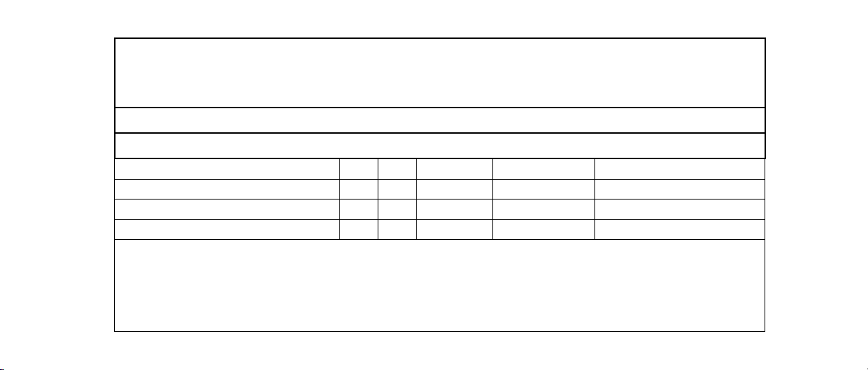
Weight and Balance/Equipment List Revision
X
X
X
X
6.9 lbs.
0
.3 lbs.
 Loading...